Article

Influence of Sputtering Pressure on the Micro-Topography of Sputtered Cu/Si Films: Integrated Multiscale Simulation

1
School of Mechanical & Electrical Engineering, Hunan City University, Yiyang 413000, China
2
School of Mechanical Science & Engineering, Huazhong University of Science & Technology, Wuhan 430074, China
*
Author to whom correspondence should be addressed.
Processes 2023, 11(6), 1649; https://doi.org/10.3390/pr11061649
Submission received: 3 April 2023 / Revised: 19 May 2023 / Accepted: 26 May 2023 / Published: 28 May 2023
(This article belongs to the Special Issue Green Particle Technologies: Processes and Applications)

Abstract

:
In this work, an integrated multiscale simulation of magnetron sputtering epitaxy was conducted to study the effect of sputtering pressure on the surface micro-topography of sputtered Cu/Si films. Simulation results indicated that, as the sputtering pressure increased from 0.15 to 2 Pa, the peak energy of the incident energy distribution gradually decreased from 2 to 0.2 eV, which might be mainly due to the gradual decrease in the proportion of deposited Cu atoms whose energy ranged from 2 to 30 eV; the peak angle of the incident polar angle distribution increased from 25° to 35°, which might be attributed to the gradual thermalization of deposited Cu atoms; the growth mode of Cu film transformed from the two-dimensional layered mode to the Volmer-Weber mode. The transformation mechanism of growth mode was analyzed in detail. A comprehensive analysis of the simulation results indicated that incident energy ranging from 2 to 30 eV and incident angle between 10° and 35° might be conducive to the two-dimensional layered growth of sputtered Cu films. This work proposes an application-oriented modeling approach for magnetron sputtering epitaxy.

1. Introduction

Copper has been widely used in the metallization of Si ultra-large scale integrated (Si-ULSI) devices, due to its high resistance to electromigration and low electrical resistivity [1,2]. Epitaxial Cu films on Si substrates have been extensively studied due to their widespread applications in photo detectors, chemical sensors, and the electrochemical reduction of CO2 to fuels [3,4,5,6,7,8]. In addition, the high electrical conductivity and ultrahigh strength of gradient nanotwinned Cu films suggest their promising application in advanced micro/nanoelectromechanical systems (MEMS) [9,10]. Recently, epitaxial Cu films on Si substrates have attracted considerable research interest for their potential application in spintronic and superconducting devices [11,12,13]. Many methods have been employed to fabricate Cu/Si films, including thermal evaporation [14], electrodeposited [15], electron beam evaporation [16], and magnetron sputtering [17,18,19]. In these epitaxial growth technologies, magnetron sputtering deposition has overriding advantages, such as high film/substrate adhesion, low deposition temperature and flexible process control [2,17,18]. The essence of the process control is that the variation in the transport process and deposition behaviors of sputtered atoms with sputtering process parameters results in the microstructural variation of the sputtered film [20]. Accordingly, an integrated and systematic investigation on the transport and deposition processes of sputtered atoms is of great significance in exploring the relationship between process parameters and the performance of Cu/Si films.
Since the transport and deposition processes of sputtered atoms cannot be real-timely monitored by experimental means, so far, the interplay between process parameters and the properties of sputtered films is indirectly evaluated by the posteriori characterization of thin film samples [21]. Under this context, numerical methods have been extensively utilized to reinforce the experiments to fully unveil the underlying mechanism. The Monte Carlo (MC) method has been extensively employed to investigate the influence of process parameters on the transport process during magnetron sputtering discharge, providing new insights into the sputtered atom transport in the gas phase [22,23,24,25,26]. Recently, Direct Simulation Monte Carlo (DSMC) code [27] and Monte Carlo Collision (MCC) code [28] have been exploited to study the thermalization of sputtered atoms. An Monte Carlo (MC) and Molecular dynamics (MD) coupling method was proposed for the sputtered atom transport [29]. In this method, the MC and MD methods were employed to model the free-flight process of a sputtered atom and the collision between the sputtered and gas atoms, respectively. Meanwhile, the MD method has been utilized to simulate the growth of Cu/Cu [30] and SiO2/SiO2 [31] films by magnetron sputtering. In these simplified MD model, all deposited atoms perpendicularly struck the substrate surface with a constant energy. Georgieva et al. [32] investigated surface diffusion processes during the growth of sputtered Mg-Al-O thin films via MD simulation. In their MD simulation, the initial velocities of deposited atoms were sampled from Maxwellian distributions. Brault et al. [33,34] studied the growth of the sputtered Al film and metal nanocatalyst via MD simulation, in which the incident energy of deposited atoms was calculated based on the Meyer’s model [35]. Based on this incident energy calculation scheme, the temperature effects on the microstructure of sputtered Cu/Si films were studied by MD simulation [36]. To our knowledge, existing numerical studies focus on either the sputtered atom transport or the growth of sputtered films. However, the numerical study combining the transport process of sputtered Cu atoms in argon gas and their deposition on the Si substrate has been rarely reported, although such a combined numerical investigation is significant for exploring the influence mechanism of process parameters on the properties of Cu/Si films.
In this work, the MC-MD coupling simulation was conducted to study the transport process of sputtered Cu atoms under different sputtering pressures and calculate the incident energy and polar angle distributions of sputtered Cu atoms as they arrived at the Si (001) substrate. The calculated incident energy and polar angle distributions were further adopted to sample the initial status data of Cu atoms in the MD simulation of the growth of the sputtered Cu/Si film. By using this integrated multiscale simulation of combined transport and deposition processes, the effect of the sputtering pressure on the surface micro-topography of the sputtered Cu/Si film was investigated. The underlying mechanism was analyzed in detail. This work proposes an application-oriented simulation approach for magnetron sputtering deposition and provides the theoretical reference for the efficient preparation of high-quality sputtered Cu/Si film.

2. Simulation Method

In this work, the transport processes of sputtered Cu atoms during DC magnetron sputtering deposition were simulated using the MC-MD coupling method. In our simulation, the DC magnetron sputtering system had a nonparallel, off-axis target-substrate configuration, in which the diameters of the target and rotating substrate were both 2 inches. This DC magnetron sputtering system is used extensively to prepare sputtered films. Argon gas was used as the sputtering gas, and the temperature of the sputtering gas was set to 300 K. The sputtering pressure was set to 0.15, 0.5 and 2 Pa, respectively.

2.1. MC-MD Simulation of the Transport of Sputtered Cu Atoms

The initial energy of the Cu atom when it was sputtered from the target surface was assumed to comply with the Thompson distribution [37], which can be expressed as
f ( E 0 ) 1 ( E b + E 0 ) / γ E Ar E 0 2 ( 1 + E b / E 0 ) 3
where E0 is the initial energy of the Cu atom; Eb is the binding energy of copper material; EAr is the impinging energy of the argon ion; γ = 4mgms/(mg + ms)2; ms and mg represent the masses of Cu and Ar atoms, respectively.
The polar emission angles of sputtered atoms were postulated to obey Yamamura’s angular distribution [38], which can be expressed as
f θ = cos θ 1 + ξ cos 2 θ
where θ is the polar angle with respect to the target surface normal, and ξ is a fitting parameter [38]. The azimuth emission angles of sputtered atoms (φ) were sampled uniformly between 0 and 2π, due to its symmetry.
Figure 1 displays the geometric structure of the magnetron sputtering system. As shown in Figure 1, the angle of the target surface normal respect to the substrate normal (β) is 25°, and the horizontal and vertical distances between the centers of the target and substrate are 60 mm and 112 mm, respectively. In Figure 1, the point m(x0, y0, z0) and vector V(vx0, vy0, vz0) denote the initial position and velocity of the sputtered atom calibrated in the local coordinate system XtYtZt, whose origin and Zt axis are located at the target center and along the normal of the target surface, respectively. To facilitate the analysis, a global coordinate system XgYgZg located at the substrate center is introduced, and its Zg axis and Xg axis are along the normal of the substrate surface and parallel to the Xt axis, respectively. Herein, m’(x1, y1, z1) and V’(vx1, vy1, vz1) are introduced and defined as the initial position and velocity of the sputtered atom calibrated in XgYgZg, respectively. According to the geometric relationship between the two coordinate systems, m’(x1, y1, z1) and V’(vx1, vy1, vz1) can be expressed as follows
x 1 y 1 z 1 = 1 0 0 0 cos β sin β 0 sin β cos β x 0 y 0 z 0 = 0 + 0 L H
v x 1 v y 1 v z 1 = 1 0 0 0 cos β sin β 0 sin β cos β v x 0 v y 0 v z 0 = 1 0 0 0 cos β sin β 0 sin β cos β V sin θ cos φ V sin θ sin φ V cos θ
Once the initial status parameters of sputtered Cu atoms were determined, their transport processes in the argon gas under different sputtering pressures were simulated by the MC-MD coupling method. The specific simulation procedure was described in our previous paper [29]. Then, the incident energy and polar angle distributions of sputtered Cu atoms when they arrived at the Si substrate can be calculated based on the results of MC-MD coupling simulation.

2.2. MD Simulation of the Growth of Sputtered Cu Film on Si Substrate

The deposition of sputtered Cu atoms onto the Si (001) surface was modeled by the molecular dynamics code LAMMPS [39]. The interaction between substrate atoms was modeled by the Tersoff potential, while the interaction between film atoms was described by the EAM potential [40,41]. Cu atom interacted with Si atom via the extended Tersoff potential [42,43].
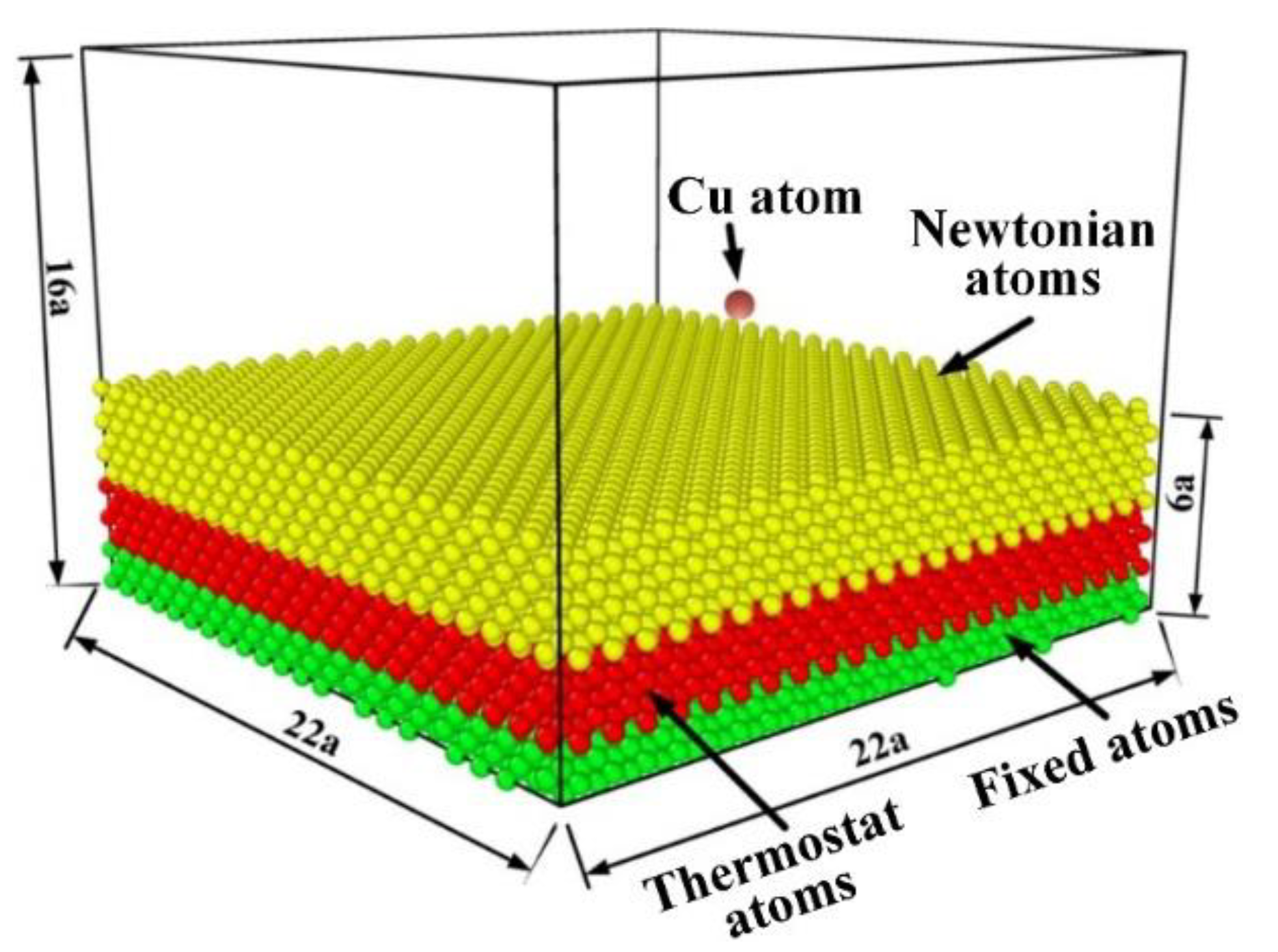
Figure 2 displays the MD model of the deposition of sputtered Cu atoms onto the Si (001) surface. The simulation domain had the dimensions of 22a × 22a × 16a (a = 5.43 Å, the lattice constant of Si), including the substrate and vacuum space. The size of the substrate was set to 22a × 22a × 6a. The z-axis, i.e., the film growth direction, was perpendicular to the (001) plane of the Si substrate. Periodic boundary conditions were applied in the X and Y directions, while a non-periodic and fixed boundary condition was imposed in the Z direction. From the bottom to the top of the substrate, the Si atoms were classified as fixed atoms, thermostat atoms, and Newtonian atoms. The fixed atoms consisted of the bottommost four layers of substrate atoms. The thermostat atoms comprised the middle twelve layers of the substrate atoms. The temperature of the thermostat domain was maintained at 300 K by rescaling the velocities of thermostat atoms every 10 fs. The substrate atoms above the thermostat domain were defined as Newtonian atoms, whose velocities were solved every 1 fs using the standard Velocity-Verlet algorithm [36].
In each simulation, 25,000 Cu atoms were deposited successively every 2 ps [36]. The vertical distance between the initial position of the deposited Cu atom and the film surface was set to 5.43 Å (the lattice constant of Si). The initial XY-coordinates of deposited Cu atoms were distributed randomly within the XY surface of the simulation box. The incident energy and polar angle of each Cu atom deposited onto the Si substrate surface were sampled from the incident energy and polar angle distributions calculated by the MC-MD coupling simulation. The incident azimuth angle of each Cu atom was sampled uniformly between 0 and 2π. The initial status data (velocities and coordinates) of deposited Cu atoms were pre-stored in external files and then read via a LAMMPS-Python interface during the simulation. When the deposition of 25,000 Cu atoms was completed, a relaxation with a duration of 10,000 ps was carried out to allow the Cu film to achieve thermal equilibrium.

3. Results

3.1. Transport Processes of One Cu Atom in Maro and Micro Sacles

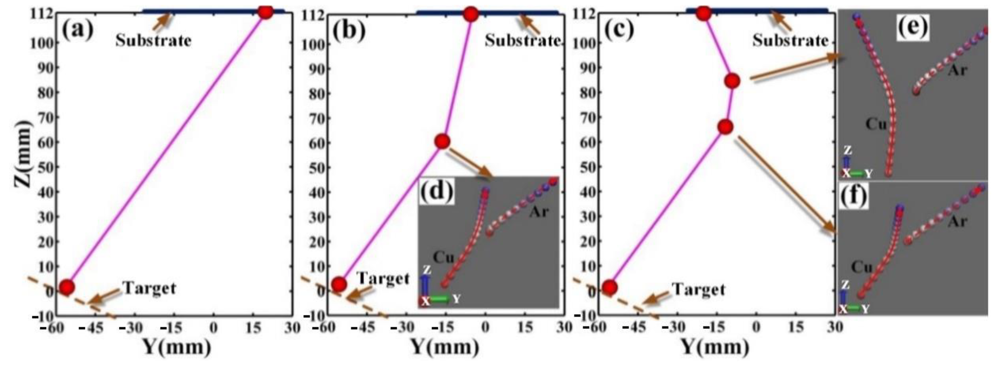
Figure 3 shows the transport processes of one Cu atom at 0.15, 0.5 and 2 Pa, respectively. Figure 3a–c depict the movement of the Cu atom in the macroscopic scale, and red balls and purple lines represent its positions and trajectories, respectively. Figure 3d–f display the collisions between Cu atom and Ar atom in the atomic scale, and the two strings of balls labelled by red arrows in each sub-graph represent the microcosmic trajectories of Cu and Ar atoms, respectively. At 0.15 Pa, the Cu atom undergoes no collisions before it reaches the substrate. At 0.5 and 2 Pa, Cu atom experiences scattering collisions since its free path is smaller than the target-substrate distance. As shown in Figure 3d–f, the spacing between two neighboring points in the trajectory of the Cu atom gradually decreases, but the case for Ar atom is reversed. This indicates the occurrence of the energy transmission from Cu atom to Ar atom. In addition, it can be seen that the scattering angles of the Cu atom in Figure 3d–f are consistent with those in Figure 3b,c. This suggests that the interconnection between the MD simulation and the MC simulation has been successfully implemented.

3.2. Incident Energy Distribution of Deposited Cu Atoms

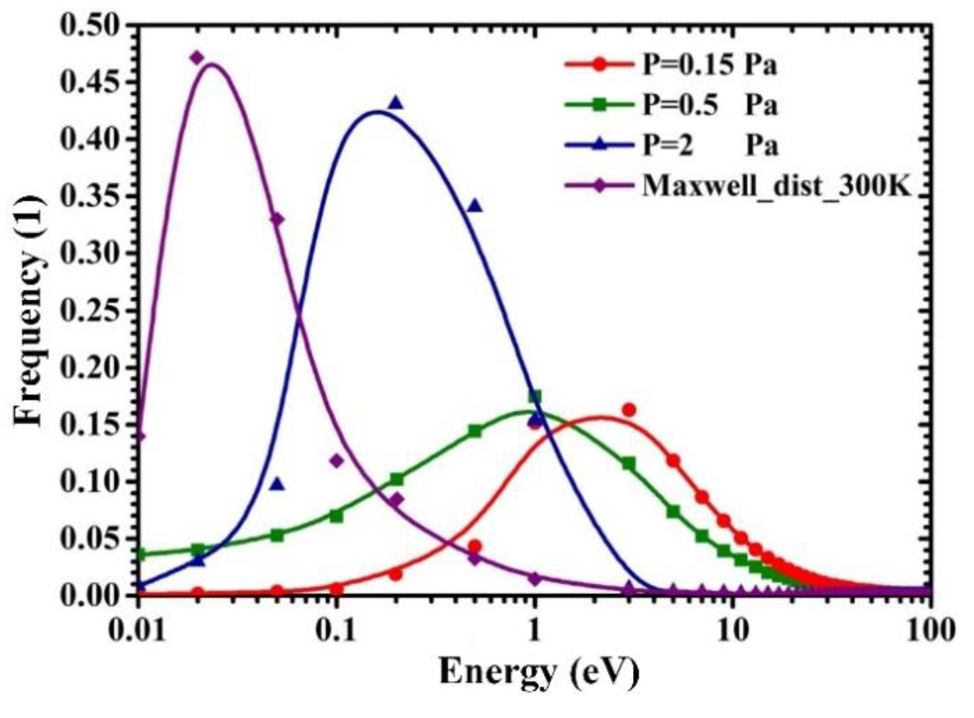
Figure 4 displays the incident energy distributions of sputtered Cu atoms when they reach the substrate surface at different sputtering pressures. As the sputtering pressure increases from 0.15 to 0.5 Pa, the ratio of Cu atoms whose energy ranges from 2 to 30 eV gradually decreases, while the proportion of Cu atoms with energy of less than 2 eV gradually increases. At 0.5 Pa, the mean free paths of sputtered Cu atoms with energy ranging from 2 to 30 eV vary from 41.6 to 113.7 mm, which are less than the distance between the centers of the target and substrate (127 mm). Thus, the energy loss of these sputtered Cu atoms due to the elastic collision during the transport process accounts for the decrease in the proportion of sputtered Cu atoms whose energy ranges from 2 to 30 eV. When the sputtering pressure further increases to 2 Pa, the incident energy distribution resembles the Maxwellian-type distribution at 300 K, which suggests that deposited Cu atoms have been in quasi thermal equilibrium. These Maxwellian-type incident energy distributions of deposited Cu atoms have also been obtained by experiment [44] and theoretical calculation [45], respectively. Furthermore, with the increase of the sputtering pressure from 0.15 to 2 Pa, the peak energy of the incident energy distribution gradually reduces from 2 to 0.2 eV, while the average incident energy of deposited Cu atoms gradually decreases from 10.19 to 0.378 eV.

3.3. Incident Polar Angle Distribution of Deposited Cu Atoms

The incident polar angle of deposited Cu atom represents the included angle between the incident direction of the deposited Cu atom and the substrate surface normal, which significantly affects the micro-topography of sputtered Cu/Si films [14]. The calculation scheme for the incident polar angle of deposited Cu atom is described in our previous paper [29]. Figure 5 depicts the influence of sputtering pressures on the incident polar angle distribution of deposited Cu atoms. These arch-shaped distribution curves are consistent well with existing theoretical calculation results [46,47]. At 0.15 Pa, the peak angle of the incident polar angle distribution of Cu atoms arriving at the substrate is 25°, and the incident polar angles of deposited Cu atoms are mainly concentrated in the range of 5° to 50°. This indicates that most of sputtering atoms are deposited on the substrate surface with a small incident angle at 0.15 Pa. As the sputtering pressure increases from 0.15 to 2 Pa, the peak angle of the incident polar angle distribution increases from 25° to 35°. The ratio of deposited Cu atoms whose incident polar angles ranges from 0° to 40° gradually reduces, while the proportion of deposited Cu atoms with the incident polar angles ranging from 40° to 80° gradually increases. This manifests the selectivity of scattering collision to the incident polar angle of the Cu atoms deposited onto the 2-inch substrate surface. At 2 Pa, the incident polar angle distribution resembles the arch-shaped distribution with the peak angle of 35°, approaching the cosθsinθ distribution. Indeed, as the gas scattering effect increases with the sputtering pressure, the incident polar angles of deposited Cu atoms will eventually comply cosθsinθ distribution with a peak angle of 45°, which suggests that deposited Cu atoms have reached thermalized equilibrium and have an isotropic velocity distribution [29,48,49]. Accordingly, the sputtered Cu atoms deposited on the substrate surface is in quasi thermal equilibrium at 2 Pa.

3.4. Surface Morphology of Deposited Cu Film

Figure 6 shows the surface morphology of sputtered Cu films deposited on Si (001) substrate under different sputtering pressures. In order to clearly display the microcosmic surface morphology of sputtered Cu films, only the near-surface Cu atoms are displayed and colored according to their Z-axis coordinate values, while Si (001) substrate is not displayed in Figure 6. As shown in Figure 6, when the sputtering pressure is 0.15 Pa, the layer-by-layer arrangement of surface Cu atoms results in the flat surface of the Cu film. It suggests that, in the local nanometer region, the sputtered Cu film grows in two-dimensional layered growth mode. When the sputtering pressure increases to 0.5 Pa, the appearance of “hill-and-valley” structure on the film surface leads to the rough surface morphology of the Cu film. This indicates that the growth mode of Cu film is varying from the two-dimensional layered growth mode to the Volmer-Weber growth mode. When the sputtering pressure further increases to 2 Pa, the number of Cu adatom islands on the film surface increases significantly, which signifies that the growth mode of copper film has been completely transformed into the Volmer-Weber growth mode [50]. The increase of the surface roughness with the sputtering pressure is consistent with the experimental observation [51,52,53].
Figure 7 shows the surface morphology of the sputtered Cu film before and after the deposition of the last 500 Cu atoms at 2 Pa, from which the microcosmic evolution mechanism of the surface morphology of the sputtered Cu film can be further analyzed. In each sub-graph, the Cu adatom islands are labelled by numbers. In Figure 7a, the slope directions of Cu adatom islands are marked by black arrows. In Figure 7b, the junction regions between adjacent adatom islands are marked by black dotted circles. Comparing Figure 7a with Figure 7b, it can be seen that in the final stage of Cu film deposition, the adatom islands are significantly enlarged, but the valleys on the film surface are hardly changed. It evidences that Cu atoms are preferentially deposited onto the surface of adatom islands. Accordingly, simulation results reveal that the shadowing effect exerts significant influence on the growth of the Cu film at 2 Pa. Furthermore, comparing Figure 7a with Figure 7b, it can be further found that the adatom islands enlarge along their slope directions, and some adjacent islands have begun to coalesce with each other in the junction regions. It can be concluded that some Cu atoms deposited on the surface of adatom islands eventually situate near their initial deposition position, leading to the vertical growth of adatom islands, while the other ones roll down along the slope directions of adatom islands, resulting in the lateral growth of adatom islands and the coalescence of adjacent adatom islands. Therefore, simulation results reveal that the falling of deposited Cu atoms along the slope directions of adatom islands plays an important role in the coalescence of adatom islands into the continuous film. This is consistent well with the “downward funneling” sedimentary dynamics model proposed by Evans [54].
Figure 8 shows the dynamic deposition process of five Cu atoms at 0.15 Pa. In Figure 8, the five Cu atoms are labelled by numbers and their deposition regions are marked by red dotted circles. As shown in Figure 8, Cu atom 1 is deposited on the film surface and ultimately migrates to the edge of a step on the film surface. Indeed, the average incident energy (10.19 eV) of deposited Cu atoms at 0.15 Pa is much higher than that of deposited Cu atoms at 2 Pa (0.378 eV). Consequently, as the sputtering pressure decreases, the increase in the incident energy of deposited Cu atoms improves their mobility on the film surface, which is conducive to the two-dimensional layered growth of the Cu film. In addition, Cu atom 2 initially lands near a step of the topmost layer. Then, it pushes out a film atom at the step edge and ultimately fills the resulting vacancy, resulting in the forward movement of the step on the topmost layer. Cu atoms 3–5 experience similar deposition processes. These “push out” exchange events have been also observed in the MD simulations of the homoepitaxy growth of Cu/Cu film, Pt/Pt film, and Ag/Ag film, respectively [55,56,57]. Stoltze et al. deemed that the “push out” exchange phenomenon was responsible for the two-dimensional layered growth of thin films at low temperature [55]. Villarba found that the probability of “push out” event increased with the energy of deposited Pt atoms [56]. As the sputtering pressure decreases from 2 to 0.15 Pa, the increase in the incident energy of deposited Cu atoms improves the probability of “push out” event which leads to the two-dimensional layered growth mode, while the decrease in the incident polar angles of deposited Cu atoms weakens the shadowing effect that causes the Volmer-Weber growth mode.

4. Discussion

As shown in Figure 4 and Figure 5, as the sputtering pressure decreases from 2 to 0.15 Pa, the proportion of deposited Cu atoms, whose incident energy ranges from 2 to 30 eV and incident polar angles ranges from 10° to 35°, gradually increases. The increase in the incident energy of deposited Cu atoms improves the probability of “push out” event which leads to the two-dimensional layered growth mode, while the decrease in the incident polar angles of deposited Cu atoms weakens the shadowing effect that causes the Volmer-Weber growth mode. This suggests that the evolution of the surface morphology of deposited films with the sputtering pressure results from the variation of the incident energy and polar angle distributions of deposited atoms, due to the scattering collisions between sputtered and background gas atoms. It is can be concluded that the incident energy ranging from 2 to 30 eV and the incident angle between 10° and 35° might be conducive to the growth of the sputtered Cu film in two-dimensional layered growth mode. Villarba et al. [56] found that the incident energy ranging from 10 to 20 eV was favorable to the near layer-by-layer growth. Mes-adi et al. [58] investigated the effect of the incident polar angle on the surface morphology of Cu/Si (001) film via MD simulation. They found that the surface morphology was almost flat when the incident angle is less than 45°. These findings are consistent with our simulation results.
Indeed, when a deposited atom encounters a surface, it will be adsorbed if it does not receive sufficient recoil momentum in the Z direction from the surface to escape from the surface potential well (−2.5 eV) [59]. The adsorption probability of the deposited atom on the surface is dependent on its incident polar angle and energy, and can be evaluated by the sticking coefficient. The sticking coefficient of the deposited Cu atom on the Cu surface is greater than 95% when the incident polar angle and energy are less than 35° and 35 eV, respectively, and then significantly decreases with the incident angle and energy [59,60,61]. Furthermore, it is known that deposited atom will induce the surface sputtering when its incident energy exceeds the sputtering threshold, which decreases with the incident polar angle [62]. For the Cu surface, the self-sputtering threshold is approximate between 40 and 50 eV at normal incidence [63,64,65] and decreases to 26 eV as the incident polar angle increases to 30° [64]. This suggests that the incident energy less than 30 eV and incident angle less than 35° not only facilitate the adsorption of Cu atoms, but also inhibit the sputtering on the Cu film surface.
Once the deposited Cu atom is trapped by the growing surface of the Cu film, it will migrate as an adatom on the film surface. For the flat Cu surface, the bridge-site hopping diffusion is more favorable than the exchange hopping diffusion [66,67,68]. The activation energies of the bridge-site hopping diffusion on the Cu(001), Cu(011), and Cu(111) surfaces are 1.19, 0.55, and 0.99 eV, respectively, while the activation energies of the exchange hopping diffusion on the Cu(001), Cu(011), and Cu(111) surfaces are 1.51, 0.61 and 2.08 eV [68], respectively. For the stepped fcc metal surface, the adatom at a step edge prefers to diffuse through the “push out” exchange process due to its less diffusion barrier than that of the direct diffusion over a descending step onto the underlying layer [69,70]. The activation energies of the “push out” exchange diffusion on the Cu(001), Cu(110), and Cu(111) surfaces are 1.22, 1.03, and 1.05 eV [68], respectively. Accordingly, for the migration of Cu adatoms on the Cu surface, the incident energy greater than 2 eV is favorable to both the hopping diffusion at the flat region and the “push out” exchange diffusion at the step.

5. Conclusions

In this work, an integrated multiscale simulation was conducted to study the evolution of the surface micro-topography of the sputtered Cu/Si film as the sputtering pressure increased from 0.15 to 2 Pa. In this integrated simulation, an MC-MD coupling method was used to simulate the transport processes of sputtered Cu atoms in the argon gas, while the MD method was further utilized to simulate the growth of the Cu film onto the Si (100) substrate based on the results of the MC-MD simulation.
The MC-MD simulation results indicated that, as the sputtering pressure increased from 0.15 to 2 Pa, the peak energy of the incident energy distribution gradually decreased from 2 to 0.2 eV. This variation of the incident energy distribution might be attributed to the gradual decrease in the proportion of deposited Cu atoms whose energy ranges from 2 to 30 eV. Furthermore, the peak angle of the incident polar angle distribution increased from 25° to 35°, which might be attributed to the gradual thermalization of deposited Cu atoms.
The MD simulation results revealed that, as the sputtering pressure increased from 0.15 to 2 Pa, the growth mode of the sputtered Cu film varied from the two-dimensional layered growth mode to the Volmer-Weber growth mode. The microcosmic deposition behaviors of the last 500 Cu atoms unveiled that the shadowing effect and “downward funneling” mechanism resulted in the Volmer-Weber growth mode, while the “push out” event led to the two-dimensional layered growth mode.
It can be further concluded that the evolution of the surface micro-topography of the sputtered Cu/Si film with the sputtering pressure is fundamentally originated from the variation in the incident energy and polar angle distributions of deposited Cu atoms due to the gas scattering effect. In particular, the incident energy ranging from 2 to 30 eV and the incident angle between 10° and 35° might be conducive to the two-dimensional layered growth of the sputtered Cu film. This work is expected to propose a more realistic simulation approach for magnetron sputtering deposition and provide a theoretical reference for the fast fabrication of high-quality sputtered Cu/Si films.

Author Contributions

Conceptualization, investigation, software, writing—review and editing, G.Z.; Investigation, data curation, writing—original draft, M.H.; Investigation, data curation, formal analysis, B.X.; Conceptualization, methodology, validation, writing-review & editing, Z.G. All authors have read and agreed to the published version of the manuscript.

Funding

This work is mainly supported by Hunan Provincial Natural Science Foundation of China (2022JJ30114). It is also in part supported by excellent youth funding from the Hunan Provincial Education Department (22B0783).

Institutional Review Board Statement

Not applicable.

Informed Consent Statement

Not applicable.

Data Availability Statement

Not applicable.

Conflicts of Interest

The authors declare no conflict of interest.

References

  1. Hu, K.; Hu, Q.F.; Xu, X.; Chen, S.H.; Ma, J.; Dong, W.W. Excellent diffusion barrier property of amorphous NbMoTaW medium entropy alloy thin films used in Cu/Si Connect System. Vacuum 2022, 202, 111195. [Google Scholar] [CrossRef]
  2. Lee, J.; Park, S.; Kim, K.; Jo, H.; Lee, D. Combined effects of residual stress and microstructure on degradation of Cu thin films on Si. Thin Solid Film. 2023, 764, 139607. [Google Scholar] [CrossRef]
  3. Theerthagiri, J.; Karuppasamy, K.; Lee, S.J.; Shwetharani, R.; Kim, H.-S.; Pasha, S.K.K.; Ashokkumar, M.; Choi, M.Y. Fundamentals and comprehensive insights on pulsed laser synthesis of advanced materials for diverse photo-and electrocatalytic applications. Light Sci. Appl. 2022, 11, 250. [Google Scholar] [CrossRef]
  4. Zhu, H.H.; Ye, X.J.; Liu, C.S.; Yan, X.H. Monolayer Cu2Si as a potential gas sensor for NOx and Cox (x = 1, 2): A first-principles study. Surf. Sci. 2018, 668, 42–46. [Google Scholar] [CrossRef]
  5. Roslan, N.A.; Supangat, A.; Sagadevan, S. Investigation of Charge Transport Properties in VTP: PC71BM Organic Schottky Diode. Electronics 2022, 11, 3777. [Google Scholar] [CrossRef]
  6. Venkatesan, R.; Sheik KadarMaideen, S.M.T.; Chandhiran, S.; Kushvaha, S.S.; Sagadevan, S.; Venkatachalapathy, V.; Mayandi, J. Fabrication and Characterization of Si/PEDOT: PSS-Based Heterojunction Solar Cells. Electronics 2022, 11, 4145. [Google Scholar] [CrossRef]
  7. Xiang, S.Q.; Gao, S.T.; Shi, J.L.; Zhang, W.; Zhao, L.B. Developing micro-kinetic model for electrocatalytic reduction of carbon dioxide on copper electrode. J. Catal. 2021, 393, 11–19. [Google Scholar] [CrossRef]
  8. Lee, S.J.; Theerthagiri, J.; Nithyadharseni, P.; Arunachalam, P.; Balaji, D.; Kumar, A.M.; Madhavan, J.; Mittal, V.; Choi, M.Y. Heteroatom-doped graphene-based materials for sustainable energy applications: A review. Renew. Sustain. Energy Rev. 2021, 143, 110849. [Google Scholar] [CrossRef]
  9. Cheng, Z.; Zhou, H.; Lu, Q.; Gao, H.; Lu, L. Extra strengthening and work hardening in gradient nanotwinned metals. Science 2018, 362, eaau1925. [Google Scholar] [CrossRef] [Green Version]
  10. Cheng, Z.; Bu, L.; Zhang, Y.; Wu, H.; Zhu, T.; Gao, H.; Lu, L. Unraveling the origin of extra strengthening in gradient nanotwinned metals. Proc. Natl. Acad. Sci. USA 2022, 119, e2116808119. [Google Scholar] [CrossRef]
  11. Kreuzpaintner, W.; Schmehl, A.; Book, A.; Mairoser, T.; Ye, J.; Wiedemann, B.; Mayr, S.; Moulin, J.F.; Stahn, J.; Gilbert, D.A.; et al. Reflectometry with Polarized Neutrons on In Situ Grown Thin Films. Phys. Status Solidi (B) 2022, 259, 2100153. [Google Scholar] [CrossRef]
  12. Vautrin, C.; Lacour, D.; Tiusan, C.; Lu, Y.; Montaigne, F.; Chshiev, M.; Weber, W.; Hehn, M. Low-Energy Spin Precession in the Molecular Field of a Magnetic Thin Film. Ann. Phys. 2021, 533, 2000470. [Google Scholar] [CrossRef]
  13. Flokstra, M.G.; Stewart, R.; Satchell, N.; Burnell, G.; Luetkens, H.; Prokscha, T.; Suter, A.; Morenzoni, E.; Langridge, S.; Lee, S.L. Manifestation of the electromagnetic proximity effect in superconductor-ferromagnet thin film structures. Appl. Phys. Lett. 2019, 115, 072602. [Google Scholar] [CrossRef] [Green Version]
  14. Chen, L.; Andrea, L.; Timalsina, Y.P.; Wang, G.C.; Lu, T.M. Engineering Epitaxial-Nanospiral Metal Films Using Dynamic Oblique Angle Deposition. Cryst. Growth Des. 2013, 13, 2075–2080. [Google Scholar] [CrossRef]
  15. Hull, C.M.; Switzer, J.A. Electrodeposited Epitaxial Cu(100) on Si(100) and Lift-Off of Single-Crystal-Like Cu(100) Foils. ACS Appl. Mater. Interfaces 2018, 10, 38596–38602. [Google Scholar] [CrossRef] [PubMed]
  16. Polat, B.D.; Keles, O. Multi-layered Cu/Si nanorods and its use for lithium ion batteries. J. Alloys Compd. 2015, 622, 418–425. [Google Scholar] [CrossRef]
  17. Boo, J.H.; Jung, M.J.; Park, H.K.; Nam, K.H.; Han, J.G. High-rate deposition of copper thin films using newly designed high-power magnetron sputtering source. Surf. Coat. Technol. 2004, 188, 721–727. [Google Scholar] [CrossRef]
  18. Cemin, F.; Lundin, D.; Furgeaud, C.; Michel, A.; Amiard, G.; Minea, T.; Abadias, G. Epitaxial growth of Cu(001) thin films onto Si(001) using a single-step HiPIMS process. Sci. Rep. 2017, 7, 1655. [Google Scholar] [CrossRef] [Green Version]
  19. Zhu, G.; Xiao, B.; Chen, G.; Gan, Z. Study on the Deposition Uniformity of Triple-Target Magnetron Co-Sputtering System: Numerical Simulation and Experiment. Materials 2022, 15, 7770. [Google Scholar] [CrossRef]
  20. Yanguas-Gil, A. Growth and Transport in Nanostructured Materials; Springer International Publishing: Cham, Switzerland, 2017. [Google Scholar] [CrossRef]
  21. Wu, B.; Haehnlein, I.; Shchelkanov, I.; McLain, J.; Patel, D.; Uhlig, J.; Jurczyk, B.; Leng, Y.; Ruzic, D.N. Cu films prepared by bipolar pulsed high power impulse magnetron sputtering. Vacuum 2018, 150, 216–221. [Google Scholar] [CrossRef]
  22. Turner, G.M.; Falconer, I.S.; James, B.W.; McKenzie, D.R. Monte Carlo calculation of the thermalization of atoms sputtered from the cathode of a sputtering discharge. J. Appl. Phys. 1989, 65, 3671–3679. [Google Scholar] [CrossRef]
  23. Nakano, T.; Mori, I.; Baba, S. The effect of ‘warm’ gas scattering on the deceleration of energetic atoms: Monte Carlo study of the sputter-deposition of compounds. Appl. Surf. Sci. 1997, 113, 642–646. [Google Scholar] [CrossRef]
  24. Yamamura, Y.; Ishida, M. Monte Carlo simulation of the thermalization of sputtered atoms and reflected atoms in the magnetron sputtering discharge. J. Vac. Sci. Technol. A 1995, 13, 101–112. [Google Scholar] [CrossRef]
  25. Van Aeken, K.; Mahieu, S.; Depla, D. The metal flux from a rotating cylindrical magnetron: A Monte Carlo simulation. J. Phys. D Appl. Phys. 2008, 41, 205307. [Google Scholar] [CrossRef]
  26. Depla, D.; Leroy, W.P. Magnetron sputter deposition as visualized by Monte Carlo modeling. Thin Solid Films 2012, 520, 6337–6354. [Google Scholar] [CrossRef]
  27. Trieschmann, J.; Mussenbrock, T. Transport of sputtered particles in capacitive sputter sources. J. Appl. Phys. 2015, 118, 033302. [Google Scholar] [CrossRef] [Green Version]
  28. Revel, A.; el Farsy, A.; de Poucques, L.; Robert, J.; Minea, T. Transition from ballistic to thermalized transport of metal-sputtered species in a DC magnetron. Plasma Sources Sci. Technol. 2021, 30, 125005. [Google Scholar] [CrossRef]
  29. Zhu, G.; Du, Q.; Xiao, B.; Chen, G.; Gan, Z. Influence of Target-Substrate Distance on the Transport Process of Sputtered Atoms: MC-MD Multiscale Coupling Simulation. Materials 2022, 15, 8904. [Google Scholar] [CrossRef]
  30. Chu, C.J.; Chen, T.C. Surface properties of film deposition using molecular dynamics simulation. Surf. Coat. Technol. 2006, 201, 1796–1804. [Google Scholar] [CrossRef]
  31. Taguchi, M.; Hamaguchi, S. MD simulations of amorphous SiO2 thin film formation in reactive sputtering deposition processes. Thin Solid Films 2007, 515, 4879–4882. [Google Scholar] [CrossRef]
  32. Georgieva, V.; Voter, A.F.; Bogaerts, A. Understanding the Surface Diffusion Processes during Magnetron Sputter-Deposition of Complex Oxide Mg–Al–O Thin Films. Cryst. Growth Des. 2011, 11, 2553–2558. [Google Scholar] [CrossRef]
  33. Ibrahim, S.; Lahboub, F.Z.; Brault, P.; Petit, A.; Caillard, A.; Millon, E.; Sauvage, T.; Fernández, A.; Thomann, A.L. Influence of helium incorporation on growth process and properties of aluminum thin films deposited by DC magnetron sputtering. Surf. Coat. Technol. 2021, 426, 127808. [Google Scholar] [CrossRef]
  34. Brault, P.; Neyts, E.C. Molecular dynamics simulations of supported metal nanocatalyst formation by plasma sputtering. Catal. Today 2015, 256, 3–12. [Google Scholar] [CrossRef] [Green Version]
  35. Meyer, K.; Schuller, I.K.; Falco, C.M. Thermalization of sputtered atoms. J. Appl. Phys. 1981, 52, 5803–5805. [Google Scholar] [CrossRef]
  36. Zhu, G.; Sun, J.; Zhang, L.; Gan, Z. Molecular dynamics simulation of temperature effects on deposition of Cu film on Si by magnetron sputtering. J. Cryst. Growth 2018, 492, 60–66. [Google Scholar] [CrossRef]
  37. Thompson, M.W., II. The energy spectrum of ejected atoms during the high energy sputtering of gold. Philos. Mag. 1968, 18, 377–414. [Google Scholar] [CrossRef]
  38. Yamamura, Y.; Takiguchi, T.; Ishida, M. Energy and angular distributions of sputtered atoms at normal incidence. Radiat. Eff. Defect. Solids 1991, 118, 237–261. [Google Scholar] [CrossRef]
  39. Thompson, A.P.; Aktulga, H.M.; Berger, R.; Bolintineanu, D.S.; Brown, W.M.; Crozier, P.S.; in ’t Veld, P.J.; Kohlmeyer, A.; Moore, S.G.; Nguyen, T.D.; et al. LAMMPS—A flexible simulation tool for particle-based materials modeling at the atomic, meso, and continuum scales. Comput. Phys. Commun. 2022, 271, 108171. [Google Scholar] [CrossRef]
  40. Tersoff, J. Modeling solid-state chemistry: Interatomic potentials for multicomponent systems. Phys. Rev. B. 1989, 39, 5566–5568. [Google Scholar] [CrossRef]
  41. Foiles, S.M.; Baskes, M.I.; Daw, M.S. Embedded-atom-method functions for the fcc metals Cu, Ag, Au, Ni, Pd, Pt, and their alloys. Phys. Rev. B 1986, 33, 7983–7991. [Google Scholar] [CrossRef]
  42. Yasukawa, A. Static Fatigue Strength Analysis of SiO2 under Atmospheric Influence Using Extended Tersoff Interatomic Potential. Trans. Jpn. Soc. Mech. Eng. A 1995, 61, 913–920. [Google Scholar] [CrossRef] [Green Version]
  43. Zhang, J.; Liu, C.; Shu, Y.; Fan, J. Growth and properties of Cu thin film deposited on Si(001) substrate: A molecular dynamics simulation study. Appl. Surf. Sci. 2012, 261, 690–696. [Google Scholar] [CrossRef] [Green Version]
  44. Kadlec, S.; Quaeyhaegens, C.; Knuyt, G.; Stals, L.M. Energy-resolved mass spectrometry and Monte Carlo simulation of atomic transport in magnetron sputtering. Surf. Coat. Technol. 1997, 97, 633–641. [Google Scholar] [CrossRef]
  45. Lu, J.; Lee, C.G. Numerical estimates for energy of sputtered target atoms and reflected Ar neutrals in sputter processes. Vacuum 2012, 86, 1134–1140. [Google Scholar] [CrossRef]
  46. Settaouti, A.; Settaouti, L. Simulation of the transport of sputtered atoms and effects of processing conditions. Appl. Surf. Sci. 2008, 254, 5750–5756. [Google Scholar] [CrossRef]
  47. Sambandam, S.N.; Bhansali, S.; Bhethanabotla, V.R.; Sood, D.K. Studies on sputtering process of multicomponent Zr–Ti–Cu–Ni–Be alloy thin films. Vacuum 2006, 80, 406–414. [Google Scholar] [CrossRef]
  48. Reif, F.; Scott, H.L. Fundamentals of Statistical and Thermal Physics. Am. J. Phys. 1998, 66, 164–167. [Google Scholar] [CrossRef]
  49. Turner, G.M.; Falconer, I.S.; James, B.W.; McKenzie, D.R. Monte Carlo calculations of the properties of sputtered atoms at a substrate surface in a magnetron discharge. J. Vac. Sci. Technol. A 1992, 10, 455–461. [Google Scholar] [CrossRef]
  50. Volmer, M.; Weber, A. Nucleus formation in supersaturated systems. Z. Phys. Chem. 1926, 119, 277–301. [Google Scholar] [CrossRef]
  51. Pletea, M.; Brückner, W.; Wendrock, H.; Kaltofen, R. Stress evolution during and after sputter deposition of Cu thin films onto Si (100) substrates under various sputtering pressures. J. Appl. Phys. 2005, 97, 054908. [Google Scholar] [CrossRef]
  52. Thornton, J.A. Influence of apparatus geometry and deposition conditions on the structure and topography of thick sputtered coatings. J. Vac. Sci. Technol. A. 1974, 11, 666. [Google Scholar] [CrossRef]
  53. Anders, A. A structure zone diagram including plasma-based deposition and ion etching. Thin Solid Films 2010, 518, 4087–4090. [Google Scholar] [CrossRef] [Green Version]
  54. Evans, J.W.; Sanders, D.E.; Thiel, P.A.; DePristo, A.E. Low-temperature epitaxial growth of thin metal films. Phys. Rev. B 1990, 41, 5410–5413. [Google Scholar] [CrossRef] [Green Version]
  55. Stoltze, P.; Norskov, J.K. Accommodation and diffusion of Cu deposited on flat and stepped Cu(111) surfaces. Phys. Rev. B 1993, 48, 5607–5611. [Google Scholar] [CrossRef] [Green Version]
  56. Villarba, M.; Jónsson, H. Atomic exchange processes in sputter deposition of Pt on Pt(111). Surf. Sci. 1995, 324, 35–46. [Google Scholar] [CrossRef]
  57. Kürpick, U.; Rahman, T.S. Diffusion processes relevant to homoepitaxial growth on Ag(100). Phys. Rev. B 1998, 57, 2482–2492. [Google Scholar] [CrossRef]
  58. Mes-adi, H.; Saadouni, K.; Mazroui, M. Effect of incident angle on the microstructure proprieties of Cu thin film deposited on Si (001) substrate. Thin Solid Films 2021, 721, 138553. [Google Scholar] [CrossRef]
  59. Hanson, D.E.; Kress, J.D.; Voter, A.F.; Liu, X.Y. Trapping and desorption of energetic Cu atoms on Cu(111) and (001) surfaces at grazing incidence. Phys. Rev. B 1999, 60, 11723–11729. [Google Scholar] [CrossRef]
  60. Liu, X.Y.; Daw, M.S.; Kress, J.D.; Hanson, D.E.; Arunachalam, V.; Coronell, D.G.; Liu, C.L.; Voter, A.F. Ion solid surface interactions in ionized copper physical vapor deposition. Thin Solid Films 2002, 422, 141–149. [Google Scholar] [CrossRef]
  61. Wu, H.; Anders, A. Energetic deposition of metal ions: Observation of self-sputtering and limited sticking for off-normal angles of incidence. J. Phys. D Appl. Phys. 2010, 43, 065206. [Google Scholar] [CrossRef] [Green Version]
  62. Eckstein, W.; Garciá-Rosales, C.; Roth, J.; László, J. Threshold energy for sputtering and its dependence on angle of incidence. Nucl. Instrum. Methods Phys. Res. B 1993, 83, 95–109. [Google Scholar] [CrossRef]
  63. Kress, J.D.; Hanson, D.E.; Voter, A.F.; Liu, C.L.; Liu, X.Y.; Coronell, D.G. Molecular dynamics simulation of Cu and Ar ion sputtering of Cu (111) surfaces. J. Vac. Sci. Technol. A 1999, 17, 2819–2825. [Google Scholar] [CrossRef]
  64. Abrams, C.F.; Graves, D.B. Cu sputtering and deposition by off-normal, near-threshold Cu+ bombardment: Molecular dynamics simulations. J. Appl. Phys. 1999, 86, 2263–2267. [Google Scholar] [CrossRef]
  65. Insepov, Z.; Norem, J.; Veitzer, S. Atomistic self-sputtering mechanisms of rf breakdown in high-gradient linacs. Nucl. Instrum. Methods Phys. Res. B 2010, 268, 642–650. [Google Scholar] [CrossRef]
  66. Liu, C.L.; Cohen, J.M.; Adams, J.B.; Voter, A.F. EAM study of surface self-diffusion of single adatoms of fcc metals Ni, Cu, Al, Ag, Au, Pd, and Pt. Surf. Sci. 1991, 253, 334–344. [Google Scholar] [CrossRef]
  67. Boisvert, G.; Lewis, L.J. Self-diffusion of adatoms, dimers, and vacancies on Cu(100). Phys. Rev. B 1997, 56, 7643–7655. [Google Scholar] [CrossRef] [Green Version]
  68. Karimi, M.; Tomkowski, T.; Vidali, G.; Biham, O. Diffusion of Cu on Cu surfaces. Phys. Rev. B 1995, 52, 5364–5374. [Google Scholar] [CrossRef]
  69. Mehl, H.; Biham, O.; Furman, I.; Karimi, M. Models for adatom diffusion on fcc (001) metal surfaces. Phys. Rev. B 1999, 60, 2106–2116. [Google Scholar] [CrossRef] [Green Version]
  70. Yu, B.D.; Scheffler, M. Ab initio study of step formation and self-diffusion on Ag(100). Phys. Rev. B 1997, 55, 13916–13924. [Google Scholar] [CrossRef] [Green Version]
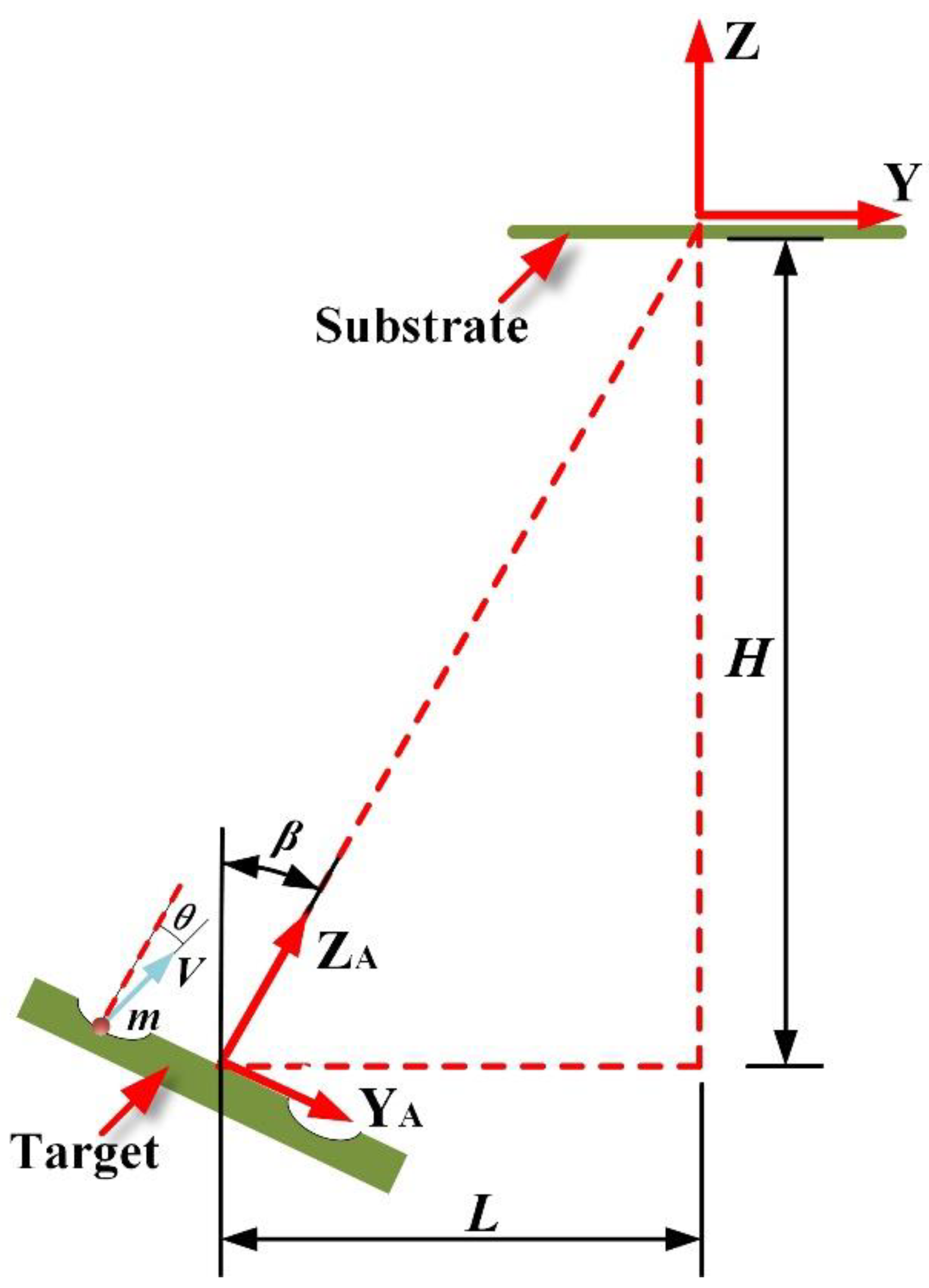
Figure 1. Geometric structure of the magnetron sputtering system with nonparallel off-axis target-substrate configuration.
Processes 11 01649 g001
Figure 2. MD model of the deposition of sputtered Cu atoms onto Si (001) surface.
Processes 11 01649 g002
Figure 3. Macroscopic trajectories of one sputtered Cu atom in the gas phase at (a) 0.15 Pa, (b) 0.5 Pa and (c) 2 Pa, and the microcosmic trajectories of Cu and Ar atoms after elastic collisions at (d) 0.5 Pa and (e,f) 2 Pa.
Processes 11 01649 g003
Figure 4. Incident energy distribution of deposited Cu atoms at different sputtering pressures.
Processes 11 01649 g004
Figure 5. Incident polar angle distribution of the deposited Cu atoms at different sputtering pressures.
Processes 11 01649 g005
Figure 6. Surface morphology of sputtered Cu films deposited at (a) 0.15 Pa, (b) 0.5 Pa, and (c) 2 Pa.
Processes 11 01649 g006
Figure 7. Surface morphology of Cu film after (a) 24,500 and (b) 25,000 Cu atoms are deposited at 2 Pa. In each sub-graph, the Cu adatom islands are labelled by number. In Figure 7a, the slope directions of Cu adatom islands are marked by black arrows. In Figure 7b, the junction regions between adjacent adatom islands are marked by black dotted circles.
Processes 11 01649 g007
Figure 8. Microcosmic deposition behaviors of five Cu atoms at 0.15 Pa. The five Cu atoms are labelled by numbers and their deposition regions are marked by red dotted circles. In each subgraph, deposited Cu atom is marked by a number, and the Cu atom labeled by “a” represents the film atom which is ultimately pushed out by the deposited Cu atom.
Processes 11 01649 g008
Disclaimer/Publisher’s Note: The statements, opinions and data contained in all publications are solely those of the individual author(s) and contributor(s) and not of MDPI and/or the editor(s). MDPI and/or the editor(s) disclaim responsibility for any injury to people or property resulting from any ideas, methods, instructions or products referred to in the content.