Article

Properties of FAPbI3-Based Alloy Perovskite Thin Films and Their Application in Solar Cells

1
Department of Electronic Engineering and Green Technology Research Center, Chang Gung University, Taoyuan 33302, Taiwan
2
Department of Otolaryngology-Head and Neck Surgery, Chang Gung Memorial Hospital, Taoyuan 33302, Taiwan
3
Department of Physics and Research Center for Semiconductor Materials and Advanced Optics, Chung Yuan Christian University, Taoyuan 320314, Taiwan
*
Authors to whom correspondence should be addressed.
Processes 2023, 11(5), 1450; https://doi.org/10.3390/pr11051450
Submission received: 31 March 2023 / Revised: 27 April 2023 / Accepted: 8 May 2023 / Published: 11 May 2023
(This article belongs to the Section Energy Systems)

Abstract

:
Surface morphologies, light harvesting abilities, crystal structures, and excitonic properties of the formamiminium lead triiodide (FAPbI3) based alloy perovskite thin films were investigated by using the scanning electron microscopic images, absorbance spectra, X-ray diffraction patterns, photoluminescence (PL) spectra and time-resolved PL decaying curves. Our experimental results show that the fresh CsxFA1−xPbI3, RbxFA1−xPbI3, and FAPb(SCNxI1−x)3 alloy thin films are a pure α-phase perovskite crystal, a α-phase: δ-phase mixed perovskite crystal, and a PbI2 crystal/α-phase: δ-phase mixed perovskite crystal at room temperatures, respectively. Among the three FAPbI3 based alloy perovskite solar cells, the CsxFA1−xPbI3 solar cells have the better photovoltaic responses. It is noted that the high photocurrent density is mainly due to the formation of cube-like surface morphology and the long carrier lifetime of 368 ns when the CsxFA1−xPbI3 alloy perovskite thin film is used as the light-absorbing layer. Our findings provide the relation between the properties of the FAPbI3 based alloy perovskite thin films and the photovoltaic responses of the resultant solar cells.

1. Introduction

Since 2009, organic and inorganic hybrid perovskite solar cells (PSCs) have been drawing substantial attention to energy harvesting applications [1,2]. PSCs’ power conversion efficiency (PCE) has risen from 10% to a world record of 25.6% [3,4], which makes them the most advanced and in-demand photovoltaic technology in the world. Their benefits include tunable bandgap, low cost, and simple production processes [5,6,7]. The high-efficiency PSCs generally use methylamine (MA) in the A-site of the ABX3 perovskites [8,9]. However, MA+ cations have a low boiling point and a high vapor pressure, which results in low thermal/chemical stability due to the dehydrogenation process [10]. Without encapsulation, the MA+ cations of MAPbI3 thin films can evaporate and thereby forming the PbI2 phase under moisture environments [11]. To improve the stability of the PSCs, it is essential to replace the MA+ cations with other appropriate organic cations which have the higher thermal/chemical stability. Although the thermal/chemical stability of formamidinium (FA)-based perovskite devices are better than that obtained using the MA+ cation, the fabricated PSCs remain elusive with their low efficiency and stability mainly due to the high thermal expansion coefficient [12], which results in the defect-sensitive crystal transition from α-phase to δ-phase [13]. For FAPbI3 perovskites, the presence of the hexagonal phase with yellow color is indicative of the thermodynamically stable phase at room temperature [14]. Useful strategies to reinforce the film’s thermal and moisture stability can be done by using inorganic additives, such as cesium (Cs+), thiocyanate (SCN), and rubidium cations (Rb+). In general, the additive concentrations are lower than 5%, which does not change the original phase of crystal structures. It was found that the cubic perovskite structure of FAPbI3 perovskites with a broader range of Goldschmidt tolerance factor can be achieved by adding Cs+ cations (5–10%) [15] due to the enhanced chemical interaction between the FA+ and I ions, which formed photoactive α-phase and low optical bandgap perovskite crystal thin films [16,17] to efficiently absorb the broadband sunlight. Despite using solid-state alloying to synthesize the CsxFA1−xPbI3 perovskites, the Cs+ doping can also be performed through the interfacial diffusion even though the nonuniform doping profile which was observed in the resultant perovskite films [18,19,20,21,22,23]. When the amount of Rb+ cations in the mixed cation perovskites is larger than 5%, yellow δ-phase perovskite crystals can be formed [24], which largely decreases the generation of photocurrents under one sun illumination. In the SCN-doped Cs0.2FA0.8PbI3 based solar cells, the optimal concentration of SCN anoions is 0.5% [25], which also forms PbI2 phase. In other words, the formation of PbI2 at the grain boundaries can stabilize the formation of SCN-doped α-phase Cs0.2FA0.8PbI3 crystals. Conceptually, the use of Cs+ or Rb+ cations in the FAPbI3based thin films can improve the stability of the α-phase perovskite crystal due to shorter Pb-I bond length and thereby resulting in the more stable Pb-I framework structure. The use of SCN-anions in the FAPbI3 based thin film can also improve the crystal grain size due to the better coordination ability. To investigate the effect of Cs+, Rb+, and SCN-ions on the properties of the resultant FAPbI3 based alloy perovskite thin films, 10% CsI, RbI, or Pb(SCN)2 was added in the FAPbI3 perovskite precursor solution before the one-step spin coating process. In such a deposition method, all the raw materials were uniformly dissolved in the solvent mixtures, then spin-coated onto the poly(3,4-ethylenedioxythiophene) (PEDOT:PSS) coated indium tin oxide (ITO)/glass substrates. Then, the sample was thermally annealed to form the CsxFA1−xPbI3, RbxFA1−xPbI3, or FAPb(SCNxI1−x)3 perovskite thin film as the light-absorbing layer. In this study, the effects of the used CsI, RbI, or Pb(SCN)2 on the structural, optical and excitonic properties of the one-step deposited FAPbI3based alloy perovskite thin films were investigated experimentally. Our experimental results show that the stronger photoluminescence (PL) intensity and the longer PL lifetime can be used to explain the improved material quality in the CsxFA1−xPbI3 alloy perovskite thin films. In addition, the use of CsI can also help to facilitate the formation of stable cubic perovskite crystals, as shown in the inset of Figure 1a. The cube-like surface morphology of the CsxFA1−xPbI3 thin film is a key indicator to explain the stable crystal structure, superior excitonic properties, and high photocurrent density. Benefiting from these factors, the fabricated CsxFA1−xPbI3 PSCs exhibit an improved output performance especially in long-term stability when 10% CsI is used.

2. Materials and Methods

FA iodide (FAI; absorber material, purity; >98%, UniRegion Bio Tech, Hsinchu, Taiwan), lead(II) iodide (PbI2; absorber material, purity; >99%, Sigma-Aldrich, St. Louis, MO, USA), Cs iodide (CsI; absorber material, 99.9%, Uni-Onward, Taoyuan, Taiwan), rubidium iodide (RbI; absorber material, purity; 99.9%, Uni-Onward), thiocyanate (Pb(SCN)2; absorber material, Uni-Onward), [6,6]-phenyl-C61-butyric acid methyl ester (PC61BM; electron transport material, purity; >99.5%, UniRegion Bio Tech), CB (solvent, >99.8%, Sigma–Aldrich), 2,9-dimethyl-4,7-diphenyl-1,10-phenanthroline (BCP; barrier, >99.5%, Lumtec, Mentor, OH, USA), poly(3,4-ethylenedioxythiophene) polystyrene sulfonate (PEDOT: PSS; hole transport layer, UniRegion Bio Tech), dimethyl sulfoxide (DMSO; solvent, >99.5%, Uni-Onward), and dimethylformamide (DMF; solvent, >99.8%, Uni-Onward) were purchased and used as received.

2.1. Solution Preparation and Device Fabrication

ITO/glass substrates were ultrasonically cleaned using a detergent, pure water, and ethyl alcohol for 20 min each. It was dried via dry air blowing and then treated with UV ozone for 40 min before the deposition of PEDOT:PSS thin films. PEDOT: PSS (70 nm thick) films were spin-coated on the ITO glass substrates at 4000 rpm for 50 s to function as the hole transport layer (HTL). After the spin-coating process, the PEDOT:PSS coated samples were heated at 100 °C for 20 min. All samples were then transferred to a glove box filled with nitrogen to continue the device fabrication process. 1 mmol PbI2 and 0.9 mmol FAI were respectively mixed with 0.1 M CsI, RbI, or Pb(SCN)2 in 1 mL anhydrous DMF/DMSO (7:3; v/v) for 12 h, which formed three clear and yellow perovskite precursor solutions. Before the deposition, the perovskite solutions were filtered through a 0.45 μm PTFE syringe filter to remove the undissolved aggregates. It is noted that the concentration of CsI, RbI, or Pb(SCN)2 additive is about 10% in the perovskite precursor solution in order to investigate the properties of the FAPbI3 based perovskite alloy thin films. In other words, the x values of the formed CsxFA1−xPbI3, RbxFA1−xPbI3, and FAPb(SCN1−xIx)3 are about 0.1. The perovskite absorbers (about 450 nm thick) were deposited onto the PEDOT:PSS films by using the spin coating method. The first (second) spin rate and first (second) spin time are 2000 rpm (5000 rpm) and 10 s (20 s), respectively. During the last 3 s of the spin-coating perovskite precursor, 200-μL chlorobenzene (CB) was dropped onto the perovskite/PEDOT:PSS/ITO/glass sample as the antisolvent. The sample was transferred to a hot plate within 2 s and kept at 100 °C for 10 min. PCBM (40 nm thick) thin film was then coated onto the perovskite layers at 1260 rpm for 60 s with a 20 mg/mL solution, which functions as an electron transport layer (ETL). After the spin-coating process, the samples, PCBM coated sample was placed in an individual round dish with a cover at room temperature for 40 min. At a deposition rate of 0.1 nm/s, BCP (6 nm thick) and Ag (100 nm thick) were sequentially deposited using thermal evaporation through a shadow mask. The area of a cell is 10 mm2. The size of perovskite solar cells can be increased to a few tens of centimeters by using the blade-coating technique [26] which is a solution process method also.

2.2. Thin Film and Device Characterizations

Perovskite/PEDOT:PSS/ITO/glass samples were characterized using scanning electron microscopy (SEM), optical spectroscopies, and X-ray diffraction (XRD). The surface images were captured using an ultra-high resolution field emission SEM (Hitachi S5200, Hitachi, Chiyoda-ku, Tokyo, Japan). A lens back scattering electron image detector and a cold cathode field emission gun (0.1 kV to 30 kV) were used in the SEM measurement system. The absorbance spectra in the 300–1200 nm wavelength range were obtained using an ultraviolet–visible–near-infrared (UV–Vis–NIR) spectrophotometer (Jasco V-670, Jasco, Oklahoma City, OK, USA). The PL spectra were measured using an optical microscope-based spectrometer (HORIBA fluorolog-3, HORIBA, Miyanohigashi-cho, Kyoto, Japan) with a 532 nm Nd:YAG laser. The PL dynamics were characterized using a time-corrected single-photon counting technique (TCSPC, picoharp-300) with a 375 nm pico-second pulsed laser. The crystal structures were analyzed using an X-ray diffractometer (Rigaku Ultima, IV, Rigaku, Tokyo, Japan). The current density–voltage (J–V) characteristics of the fabricated PSCs were recorded using a power source meter (Keithley 2400, Keithley, Solon, OH, USA) under 100 mW/cm2 irradiation from an AM1.5G sun simulator (Oriel 96000 150 W Xe lamp, Newport, Irvine, CA, USA). The intensity of the light was calibrated using a reference solar cell and meter(Oriel 91150V, Newport, Irvine, CA, USA). The calibrations of the reference cell and meter were certified by NIST to the ISO-17025 standard. The active area of the reference cell is 2 cm×2 cm which is larger than the active area of the measured PSCs. The J-V curves were measured under the forward (backward) scanning direction from −0.1 V (1.1 V) to 1.1 V (−0.1 V) with a fixed scanning rate of 1.56 V/s. The PSCs were measured without encapsulation, which can be used to evaluate the thermal/chemical stabilities of the FAPbI3 based alloy perovskite thin films under one sun illumination for 500 h. The external quantum efficiency (EQE)of the fabricated PSCs was characterized through a detector responsivity measurement system (Zolix, DSR100, Zolix, Xi’an, China) with a 75-W tungsten halogen lamp, monochromator, optical chopper, and a lock-in amplifier. Pre-calibration was performed using a standard Si photo-detector (Zolix, DSR-A1). The illumination intensity is about 100 μw/cm2.

3. Results and Discussion

The surface morphologies of the CsxFA1−xPbI3, RbxFA1−xPbI3, and FAPb(SCNxI1−x)3 perovskite films are depicted in Figure 1a–c. All three perovskite films exhibit different morphological features in terms of the surface coverage, film conformity, and crystal structure. The CsxFA1−xPbI3 alloy perovskite thin films are smooth, dense grain, wellness coverage, and have no visible pinholes. Although the grain sizes of the RbxFA1−xPbI3thin film are larger than that of the CsxFA1−xPbI3 alloy perovskite thin film, the pinholes are observed in the RbxFA1−xPbI3thin film, which is detrimental to the device performance [27]. In contrast, the use of the CSI is useful to facilitate film reconstruction through effective mass transport so that better film quality of the CsxFA1−xPbI3 perovskites can be achieved [28]. It is noted that the shape of the grains looks like merged cubes, which means the formation of cubic FAPbI3 perovskites when 10% CsI or RbI is used as the additive. In addition, the RbxFA1−xPbI3 and FAPb(SCNxI1−x)3alloy perovskite thin films have pinholes, which can negatively affect device performance. The small grain sizes range from 200 nm to 300 nm, which means the formation of residual compressive stress in the CsxFA1−xPbI3 alloy perovskite thin film and thereby resisting the formation of tensile stress during the thermal annealing process. In other words, the larger gains result in the pinholes in the RbxFA1−xPbI3 thin film, which can release the tensile stress during the thermal annealing process. In the FAPb(SCNxI1−x)3 alloy perovskite thin film, the surface morphology shows the formations of merged grains and pinholes, which means that the resultant film is not a pure cubic phase. In addition, the CsxFA1−xPbI3alloy perovskites have a higher segregation activation energy and thereby suppressing the formations of CsPbI3 and FAPbI3, which may result in the reduced ion migrations and/or non-photoactive phase formation [28,29]. The insets in Figure 1a,c are used to indicate the formation of α-phase FAPbI3 and distorted α-phase FAPbI3 crystal structures. The absorbance spectra of the CsxFA1−xPbI3, RbxFA1−xPbI3, and FAPb(SCNxI1−x)3alloy perovskites on ITO glass substrates are shown in Figure 1d. In comparison with the RbxFA1−xPbI3 and FAPb(SCNxI1−x)3 alloy perovskite films, the CsxFA1−xPbI3 alloy perovskite thin film shows the larger absorbance values in the wavelength range from 530 nm to 780 nm, which can be attributed to the formation of a pure α-phase perovskite. The larger absorbance value can result in a higher JSC value of the result PSC. Besides, the two prominent peaks at about 390 nm and 495 nm [30,31] show that the RbxFA1−xPbI3 and FAPb(SCNxI1−x)3 perovskites may contain partial δ-FAPbI3 perovskite and PbI2 phase. The δ-FAPbI3 and PbI2 are photo-inactive and large bandgap materials, which can result in low JSC values. In the transparent wavelength range from 800 nm to 1200 nm, the larger amplitude of the thin-film interference ripple indicates the formation of smoother perovskite thin film. In other words, the CsxFA1−xPbI3 alloy perovskite thin film has a flat surface, which is consistent with the formation of the closely-packed thin film. The smooth and pinhole-free perovskite thin film can be effectively covered by a 50-nm thick PCBM thin film, which can result in a higher FF.
Figure 2a depicts the steady-state PL spectra of the CsxFA1−xPbI3, RbxFA1−xPbI3, and FAPb(SCNxI1−x)3alloy perovskites on PEDOT:PSS/glass substrates. The PL intensity of the CsxFA1−xPbI3 perovskites is higher than that of other perovskites. All alloy perovskite films display an emission peak wavelength of about 790 nm, which indicates the formation of photoactive α-phase perovskites. In other words, the α-phase CsxFA1−xPbI3 thin film can effectively absorb lights and emit light. After the light absorption, the excitons (electron-hole pairs) are formed in the perovskite thin film. The light emission is via the radiatively recombination of the excitons. The information gained from the PL measurements suggests that the CsxFA1−xPbI3alloy perovskite thin film has a longer carrier lifetime compared to the other ones. The stronger PL intensity found in the CsxFA1−xPbI3thin film corresponds to the lower defect density or the weaker trap-state induced nonradiative recombination [32,33]. Figure 2b shows the three TRPL curves which can be well fitted by a biexponential decay equation with a fast and a slow decay constant associated with different recombination processes [34]. After the alloy perovskites are excited by a 375 nm pulsed laser, the presence of fast decay in PL intensity is mostly due to trap-assisted exciton recombination, and then the radiative recombination-related PL decay (slow decay) is presented [35,36]. The CsxFA1−xPbI3alloy perovskite thin films show a longer lifetime of 368 ns, which can be used to explain the stronger PL intensity given by these alloy perovskite films. As a result of poor film quality, the relatively small lifetime of 78 ns and 129 ns are obtained for the RbxFA1−xPbI3 and FAPb(SCNxI1−x)3alloy perovskite thin films, respectively.
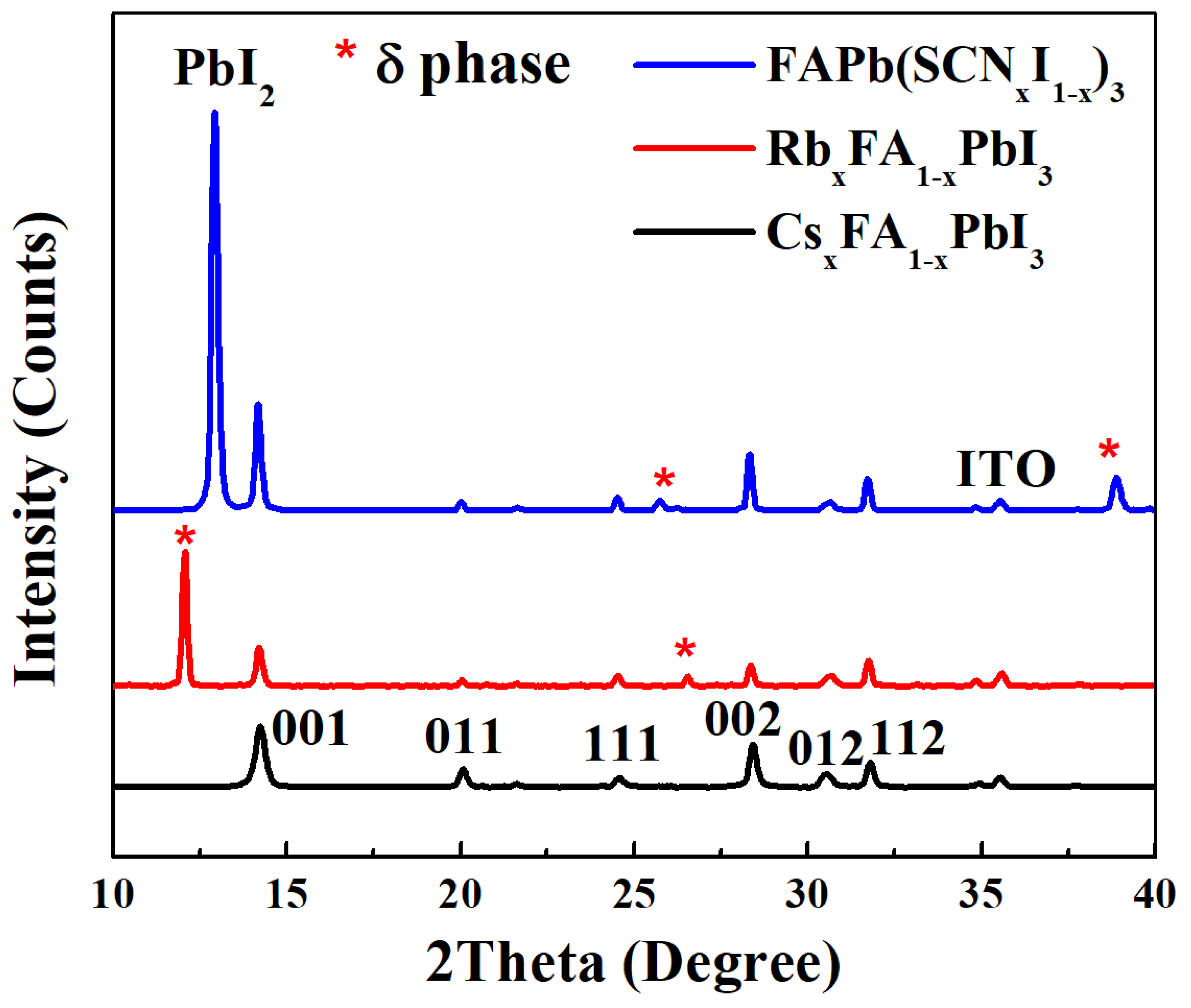
Figure 3 depicts the effect of the used CsI, RbI, and Pb(SCN)2 on the FAPbI3 based alloy perovskite structure. The main diffraction peaks of the alloy perovskite thin films can be found at 14.1°, 20.0°, 28.3°, and 31.7°, which correspond to the cubic crystal planes of (100), (110), (200), and (211), respectively [37]. The diffraction peaks at 12.0°, 25.7°, 26.6°, and 38.9° can be assigned to the δ-phase perovskite [37]. The absence of the characteristic peaks at12.0°, 25.7°, 26.6°, and 38.9° in the CsxFA1−xPbI3thin film suggests a completed phase transformation from the yellow δ-phase to the black α-phase during the fabrication process. In other words, the CsxFA1−xPbI3thin film has a pure α-phase perovskite, which confirms the prediction from the SEM image (see Figure 1a). The peak located at 12.0° in the RbxFA1−xPbI3 thin film and the peak located at 12.9° in the FAPb(SCNxI1−x)3thin film can be assigned to the δ-phase perovskite and PbI2 phase, respectively. There is a slight shift in the peak angle of theCsxFA1−xPbI3alloy perovskites compared to the other ones, which is due to the use of smaller Cs+ cations in the FAPbI3 based alloy perovskite. The ionic radius values of FA+ cations and Cs+ cations are 2.79 Å and 1.81 Å, respectively [38,39]. It can be used to explain the formation of residual compressive stress in the CsxFA1−xPbI3 thin film. As a result of the stronger electrostatic interaction between the I anions and Cs+ ions, a more stable perovskite structure can be formed accordingly [40]. In RbxFA1−xPbI3 thin film, the absence of the PbI2 phase and the formation of δ-phase perovskite indicate that the reduced lattice constant strengths the chemical stability and locally results in anisotropic lattice constants. It is possible to reduce the formation of δ-FAPbI3 by decreasing the concentration of the RbI additive used in the perovskite precursor solution. It is predicted that the δ-phase perovskites are mainly distributed at the grain boundaries of α-phase perovskites [41]. In the FAPb(SCNxI1−x)3thin film, the SCN anions can replace the iodide anions in the Pb-I framework structure and thereby resulting in the formation of the PbI2 phase at the grain boundaries [42]. Besides, the replacement of I ions with SCN ions also locally results in anisotropic lattice constants in the α-phase perovskite crystals and thereby activating the formation of δ-phase perovskite crystals.
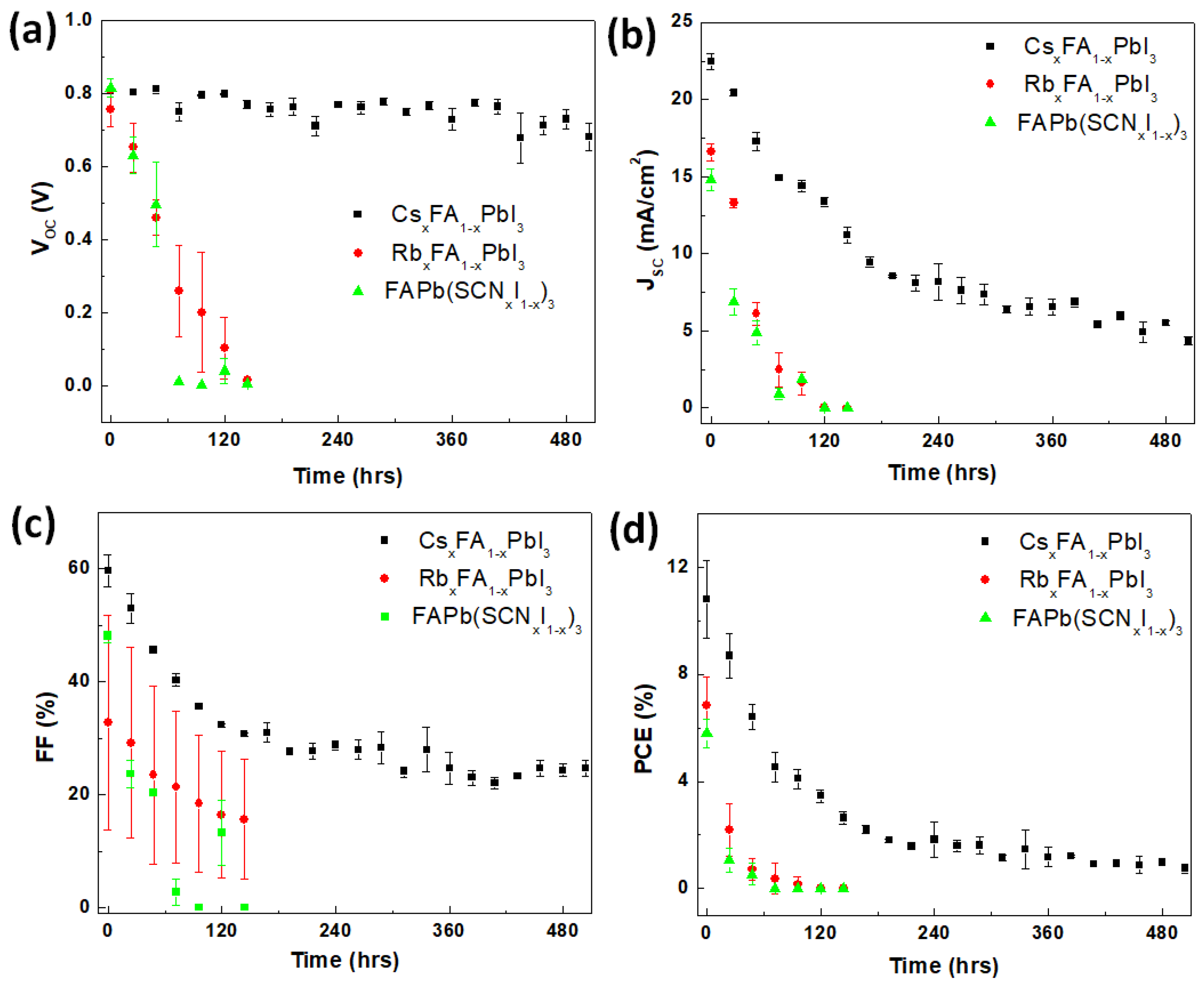
The long-term stability of the PSCs is of substantial importance for commercialization. To evaluate the thermal/chemical stability of the encapsulated PSCs, the photovoltaic responses were recorded for more than 500 h, as shown in Figure 4. During the stability tests, the PSCs were stored in an ambient atmosphere (30–60% relative humidity) at room temperatures ranging from 20 °C to 30 °C. The short-circuit current density (JSC) and fill factor (FF) both decrease with the time during the evaluation period. In the CsxFA1−xPbI3PSCs, the eVOC values are about 0.8 eV which is close to the energy difference between the Fermi levels of PEDOT:PSS thin film (−5.1 eV) and Ag thin film (−4.3 eV). The stable VOC value means that layer structures of the CsxFA1−xPbI3 PSCs are not significantly changed after 500 h. However, the average JSC (FF) value of the un-encapsulatedCsxFA1−xPbI3 PSCs largely decreases from 22 mA/cm2(60%) to 5 mA/cm2 (25%) with the increase in the time from 0 to 500 h, which is mainly due to crystal transition from α-phase to δ-phase. The dehydrogenation of PSS polymers in the top region of the PEDOT:PSS thin film [43] results in the formation of HI in the bottom region of the alloy perovskite thin film, which activates the crystal transition from the α-phase to the δ-phase. In other words, it is possible to form stable α-phase CsxFA1−xPbI3 PSCs when the PEDOT:PSS thin film is replaced by other chemical-stable HTLs. After about 170 h, the RbxFA1−xPbI3 and FAPb(SCNxI1−x)3 PSCs lose the photovoltaic responses, which is probably due to the formation of pinholes in the active layer (see Figure 1b,c).
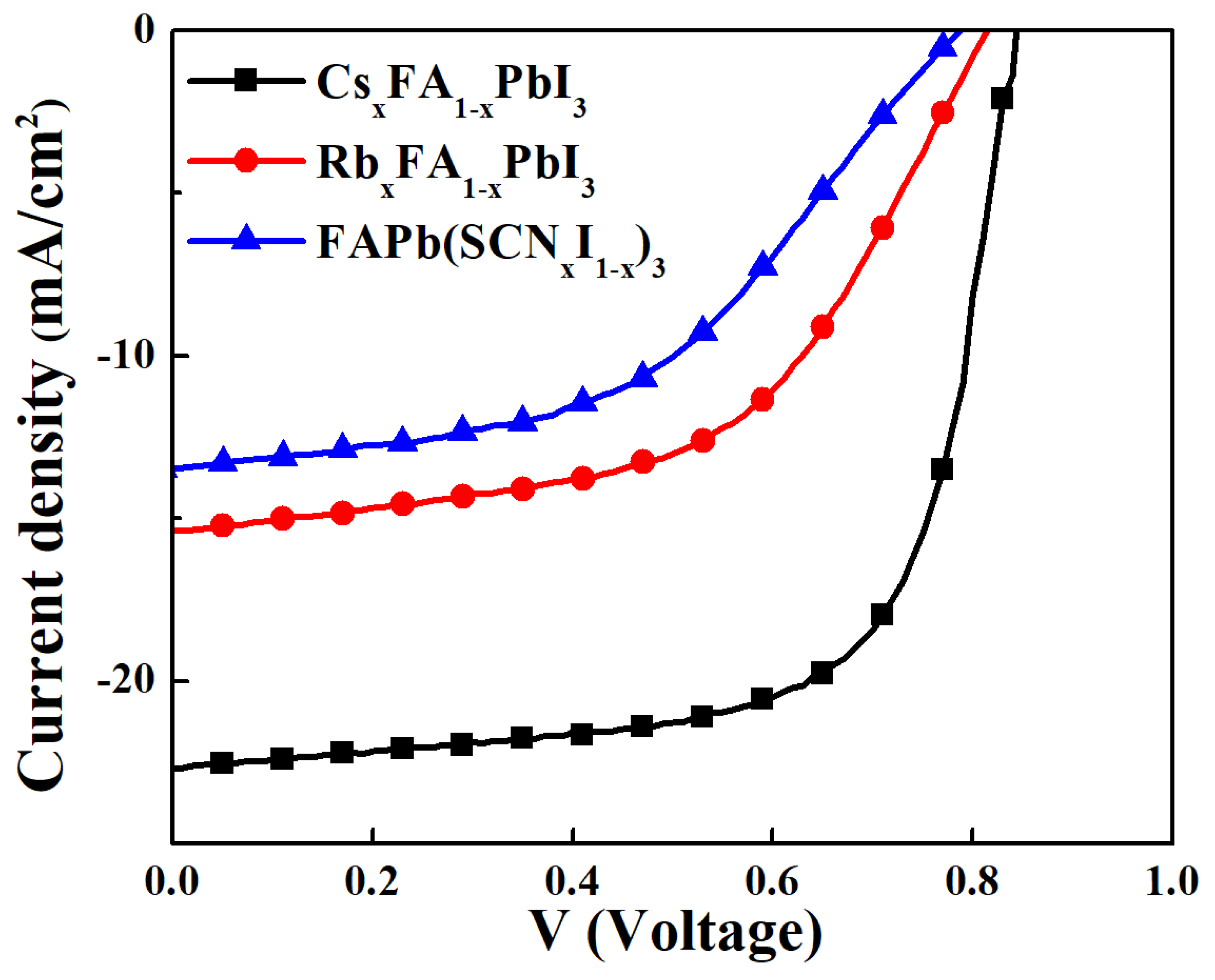
Figure 5 depicts the J–V curves (measured under AM1.5G illumination) of the CsxFA1−xPbI3, RbxFA1−xPbI3, and FAPb(SCNxI1−x)3PSCs. The photovoltaic responses of the fabricated PSCs are summarized in Table 1. The optimal CsxFA1−xPbI3 PSCs exhibit a PCE of 12.98%, VOCof 0.84 V, JSCof 22.6 mA/cm2, and FF of 68%. As a result of the stabilized cubic perovskite crystal structure, the photovoltaic performance of CsxFA1−xPbI3PSCs is superior to that of RbxFA1−xPbI3, and FAPb(SCNxI1−x)3PSCs when the concentrations of CsI, RbI, and Pb(SCN)2 are about 10%. In the fresh RbxFA1−xPbI3 and FAPb(SCNxI1−x)3PSCs, the JSC values are lower than 20 mA/cm2, which can be explained due to the formations of δ-phase perovskite and PbI2 phase at the α-phase perovskite grain boundaries. The formation of larger bandgap δ-phase perovskite or PbI2 in between the PCBM/α-phase perovskite does not form significant s-shaped characteristic in the J-V curves [44,45], which means that the δ-phase perovskite or PbI2 is not a continuous layer in the top region of the alloy perovskite thin film. The PCE of the resultant solar cells is also proportional to the series resistance, which indicates that the defect density values of the three perovskite thin films are different. To evaluate the trend of the defect densities of the CsxFA1−xPbI3, RbxFA1−xPbI3, and FAPb(SCNxI1−x)3 thin films, the intensity hysteresis values are calculated from the forward and backward J-V curves, as shown in Figure 6. The integration range is from 0 V to VOC value. The integration intensity values are listed in Table 2. When CsI or RbI is used as the additive, the intensity hysteresis (intensity difference) value is positive, which indicates the existence of iodine vacancies in the alloy perovskite thin films because the iodine vacancy is a shallow defect that can be filled during the forward scanning measurement period and thereby reducing the visible defects during the backward scanning measurement period [46]. When Pb(SCN)2 is used as the additive, the intensity hysteresis value is a larger negative value compared to the other two cases, which means that the defect density in the FAPb(SCNxI1−x)3 alloy perovskite thin film is higher. Besides, the negative intensity hysteresis value indicates that the main defects are electron-rich defects [47].
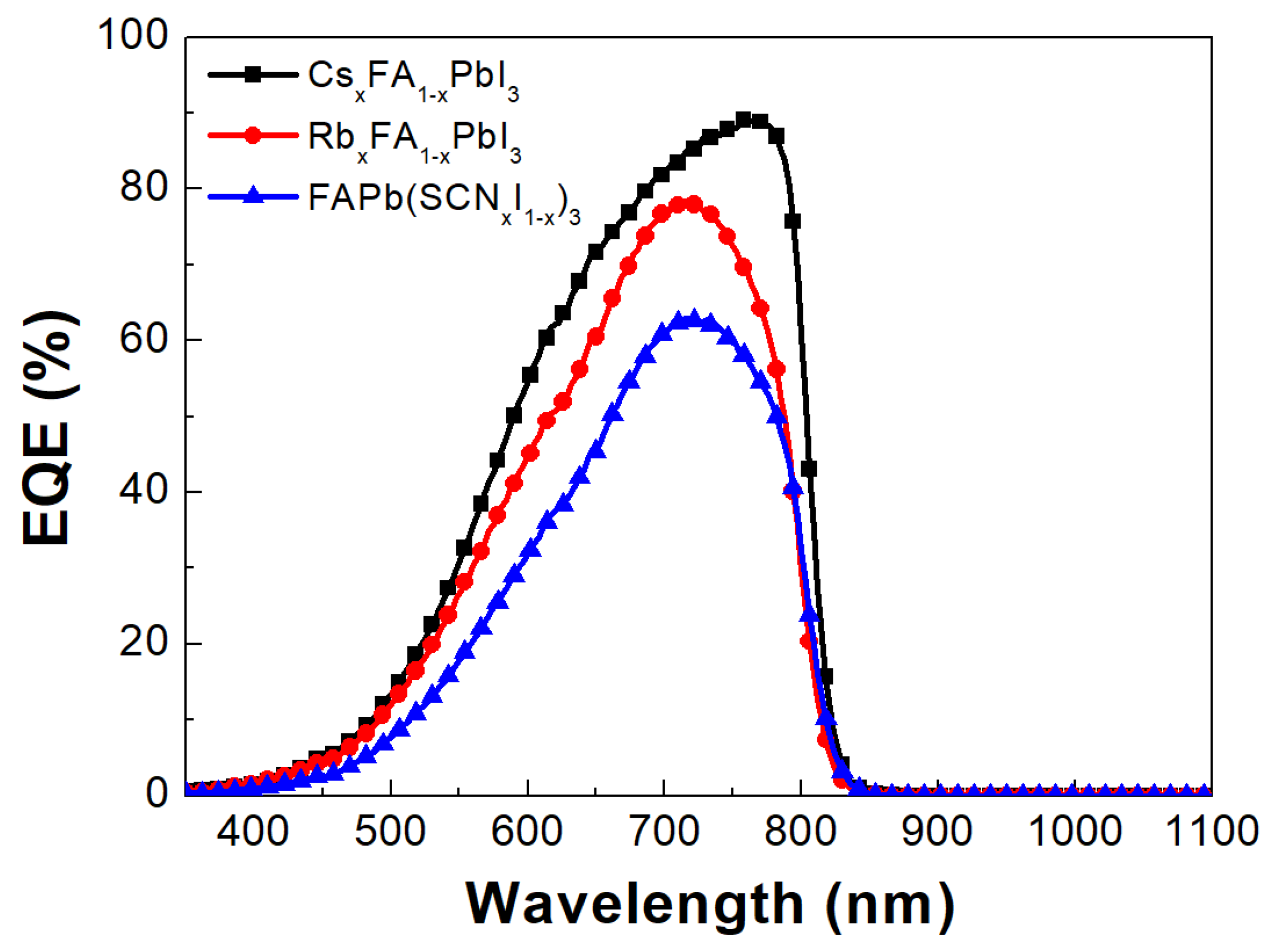
The CsxFA1−xPbI3PSCs have high JSC values, indicating that the perovskite active layer can effectively convert the sunlight into free carriers due to the larger absorbance value of 2.39 at the wavelength of 500 nm and the long carrier lifetime of 368 ns. However, the relatively low VOC values are mainly due to the smaller work function of the used PEDOT:PSS thin film. In other words, the VOC of the CsxFA1−xPbI3 PSCs can be increased by increasing the work function of PEDOT:PSS thin films [48,49]. To evaluate the importance of our findings, the PCE values of the various PEDOT:PSS HTL based FAPbI3 solar cells are listed in Table 3. In this study, the x value of the CsxFA1−xPbI3 alloy perovskite is about 0.1, which forms a pure α-phase perovskite. However, the lower PCE of the PEDOT:PSS HTL based CsxFA1−xPbI3 PSC is mainly due to the relatively lower VOC value when compared to the RbCl-doped PEDOT:PSS HTL MA0.7FA0.3PbI3 PSCs, which means that it is possible to improve the PCE of the CsxFA1−xPbI3 PSCs by using other alternative HTLs. When comparing the PEDOT:PSS HTL based CsxFA1−xPbI3 PSCs with the FPI-doped PEDOT:PSS HTL based MA0.4FA0.6Sn0.4Pb0.6I3 PSCs, the higher VOC means the lower potential loss of the PSCs, which explains the formation of a pure α-phase CsxFA1−xPbI3 alloy perovskite. To confirm the trend of the JSC values in Figure 5 and Table 1, the EQE spectra of the three PSCs were measured (see Figure 7). In the CsxFA1−xPbI3 alloy perovskite solar cell, a high EQE of 89.5% is achieved at the wavelength of 767 nm, which means the formation of a high-quality α-phase CsxFA1−xPbI3 alloy perovskite thin film. It is noted that the EQE values decrease with the decrease in the wavelength from 750 nm to 350 nm under a low light illumination (100 μW/cm2), which means that the short-wavelength photon-generated electrons suffer high carrier recombination and thereby reducing the photo-carrier generation efficiency. In other words, the electron mobility is lower than the hole mobility in the resultant perovskite thin films [50]. On the other hand, the observable EQE values in the wavelength range from 800 nm to 850 nm probably originated from the bipolaron transition of the PEDOT:PSS thin film [51], which slightly extends the spectral range of the solar cells.

4. Conclusions

In summary, we have understood the rules of Cs+ cation, Rb+ cation, and SCN anion in the FAPbI3 based alloy perovskite thin films via analyzing the surface morphologies, crystal structures and excitonic properties. It is noted that the use of 10% CsI in the FAPbI3 precursor solution can form a pure α-phase alloy perovskite thin film which is an efficient light absorber. In the PEODT:PSS hole-transport-layer based perovskite solar cells, the short-circuit current density value can be higher than 22.5 mA/cm2, which means that the CsxFA1−xPbI3 alloy perovskite thin film can effectively absorb the incident sunlight and thereby efficiently forming photocurrents. The highest open-circuit voltage is about 0.84 V which is close to the theoretical value when the PEDOT:PSS and PCBM thin films are used as the hole transport layer (HTL) and electron transport layer (ETL), respectively. In other words, the power conversion efficiency of the CsxFA1−xPbI3 alloy perovskite solar cells can be increased by using other potential HTLs and ETLs.

Author Contributions

Conceptualization, C.-L.T., S.N.M. and M.-J.J.; methodology, C.-L.T. and S.N.M.; validation, S.N.M. and C.-H.C.; investigation, S.N.M. and C.-H.C.; writing—original draft preparation, C.-L.T., S.N.M. and M.S.; writing—review and editing, C.-L.T., S.H.C., S.N.M. and M.S.; supervision, C.-L.T., M.-J.J., S.H.C., C.-T.Y. and L.-B.C. All authors have read and agreed to the published version of the manuscript.

Funding

This research was funded by the National Science and Technology Council (Taiwan) under Grant MOST 110-2221-E-182-056-MY2, 110-2622-E-182-007 and 108-2221-E-182-055, and in part by Chang Gung Memorial Hospital, Linkou under Grants BMRP 999, CMRPD2K0201 and CMRPD2K0202. And the APC was funded by Chang Gung Memorial Hospital, Linkou under Grants BMRP 999.

Data Availability Statement

Not applicable.

Conflicts of Interest

The authors declare no conflict of interest.

References

  1. Saliba, M.; Correa-Baena, J.P.; Grätzel, M.; Hagfeldt, A.; Abate, A. Perovskite Solar Cells: From the Atomic Level to Film Quality and Device Performance. Angew. Chem.—Int. Ed. 2018, 57, 2554–2569. [Google Scholar] [CrossRef]
  2. Boix, P.; Nonomura, K.; Mathews, N.; Mhaisalkar, S.G. 2014 undefined. Current progress and future perspectives for organic/inorganic perovskite solar cells. Mater. Today 2014, 17, 16–23. [Google Scholar] [CrossRef]
  3. Jeong, J.; Kim, M.; Seo, J.; Lu, H.; Ahlawat, P.; Mishra, A.; Yang, Y.; Hope, M.A.; Eickemeyer, F.T.; Kim, M.; et al. Pseudo-halide anion engineering for α-FAPbI3 perovskite solar cells. Nature 2021, 592, 381–385. [Google Scholar] [CrossRef] [PubMed]
  4. Bu, T.; Li, J.; Li, H.; Tian, C.; Su, J.; Tong, G.; Ono, L.K.; Wang, C.; Lin, Z.; Chai, N.; et al. Lead halide-templated crystallization of methylamine-free perovskite for efficient photovoltaic modules. Science 2021, 372, 1327–1332. [Google Scholar] [CrossRef] [PubMed]
  5. Bi, D.; Yi, C.; Luo, J.; Décoppet, J.D.; Zhang, F.; Zakeeruddin, S.M.; Li, X.; Hagfeldt, A.; Grätzel, M. Polymer-templated nucleation and crystal growth of perovskite films for solar cells with efficiency greater than 21%. Nat. Energy 2016, 1, 16142. [Google Scholar] [CrossRef]
  6. Burschka, J.; Pellet, N.; Moon, S.J.; Humphry-Baker, R.; Gao, P.; Nazeeruddin, M.K.; Grätzel, M. Sequential deposition as a route to high-performance perovskite-sensitized solar cells. Nature 2013, 499, 316–319. [Google Scholar] [CrossRef] [PubMed]
  7. Manjunatha, S.N.; Chu, Y.X.; Jeng, M.J.; Chang, L.B. The Characteristics of Perovskite Solar Cells Fabricated Using DMF and DMSO/GBL Solvents. J. Electron. Mater. 2020, 49, 6823–6828. [Google Scholar] [CrossRef]
  8. Li, Z.; Yang, M.; Park, J.S.; Wei, S.H.; Berry, J.J.; Zhu, K. Stabilizing Perovskite Structures by Tuning Tolerance Factor: Formation of Formamidinium and Cesium Lead Iodide Solid-State Alloys. Chem. Mater. 2016, 28, 284–292. [Google Scholar] [CrossRef]
  9. Nasti, G.; Abate, A.; Nasti, G.; Abate, A. Tin Halide Perovskite (ASnX3) Solar Cells: A Comprehensive Guide toward the Highest Power Conversion Efficiency. Adv. Energy Mater. 2020, 10, 1902467. [Google Scholar] [CrossRef]
  10. Tang, S.; Huang, S.; Wilson, G.; Ho-Baillie, A. Progress and opportunities for Cs incorporated perovskite photovoltaics. Trends Chem. 2020, 2, 638–653. [Google Scholar] [CrossRef]
  11. Park, B.; Seok, S.I. Intrinsic instability of inorganic–organic hybrid halide perovskite materials. Adv. Mater. 2019, 31, 1805337. [Google Scholar] [CrossRef]
  12. Yu, D.; Hu, Y.; Shi, J.; Tang, H.; Zhang, W.; Meng, Q.; Han, H.; Ning, Z.; Tian, H. Stability improvement under high efficiency—Next stage development of perovskite solar cells. Sci. China Chem. 2019, 62, 684–707. [Google Scholar] [CrossRef]
  13. Tan, S.; Yavuz, I.; Weber, M.H.; Huang, T.; Chen, C.H.; Wang, R.; Wang, H.C.; Ko, J.H.; Nuryyeva, S.; Xue, J.; et al. Shallow indine defects accelerate the degradation of a-phase formamidinium perovskite. Joule 2020, 4, 2426–2442. [Google Scholar] [CrossRef]
  14. Tang, Y.; Gu, Z.; Fu, C.; Xiao, Q.; Zhang, S.; Zhang, Y.; Song, Y. FAPbI3 Perovskite Solar Cells: From Film Morphology Regulation to Device Optimization. Sol. RRL 2022, 6, 2200120. [Google Scholar] [CrossRef]
  15. Haris, M.P.U.; Kazim, S.; Ahmad, S. Low-temperature-processed perovskite solar cells fabricated from presynehesized CsFAPbI3 powder. ACS Appl. Energy Mater. 2021, 4, 2600–2606. [Google Scholar]
  16. Yang, W.S.; Noh, J.H.; Jeon, N.J.; Kim, Y.C.; Ryu, S.; Seo, J.; Seok, S., Il. High-performance photovoltaic perovskite layers fabricated through intramolecular exchange. Science 2015, 348, 1234–1237. [Google Scholar] [CrossRef]
  17. Ono, L.K.; Juarez-Perez, E.J.; Qi, Y. Progress on Perovskite Materials and Solar Cells with Mixed Cations and Halide Anions. ACS Appl. Mater. Interfaces 2017, 9, 30197–30246. [Google Scholar] [CrossRef] [PubMed] [Green Version]
  18. Schelhas, L.T.; Li, Z.; Christians, J.A.; Goyal, A.; Kairys, P.; Harvey, S.P.; Kim, D.H.; Stone, K.H.; Luther, J.M.; Zhu, K.; et al. Insights into operational stability and processing of halide perovskite active layers. Energy Environ. Sci. 2019, 12, 1341–1348. [Google Scholar] [CrossRef]
  19. Lee, J.-W.; Kim, D.-H.; Kim, H.-S.; Seo, S.-W.; Min Cho, S.; Park, N.-G.; Lee, J.; Kim, D.; Kim, H.; Seo, S.; et al. Formamidinium and Cesium Hybridization for Photo- and Moisture-Stable Perovskite Solar Cell. Adv. Energy Mater. 2015, 5, 1501310. [Google Scholar] [CrossRef]
  20. Yi, C.; Luo, J.; Meloni, S.; Boziki, A.; Ashari-Astani, N.; Grätzel, C.; Zakeeruddin, S.M.; Röthlisberger, U.; Grätzel, M. Entropic stabilization of mixed A-cation ABX3 metal halide perovskites for high performance perovskite solar cells. Energy Environ. Sci. 2016, 9, 656–662. [Google Scholar] [CrossRef]
  21. Wang, Z.; Lin, Q.; Chmiel, F.; Sakai, N.; Herz, L.M.; Snaith, H.J. Efficient ambient-air-stable solar cells with 2D–3D heterostructured butylammonium-caesium-formamidinium lead halide perovskites. Nat. Energy 2017, 2, 17135. [Google Scholar] [CrossRef]
  22. Xia, X.; Wu, W.; Li, H.; Zheng, B.; Xue, Y.; Xu, J.; Zhang, D.; Gao, C.; Liu, X. Spray reaction prepared FA1−xCsxPbI3 solid solution as a light harvester for perovskite solar cells with improved humidity stability. RSC Adv. 2016, 6, 14792–14798. [Google Scholar] [CrossRef]
  23. Manzoor, S.; Häusele, J.; Bush, K.A.; Palmstrom, A.F.; Carpenter, J.; Yu, Z.J.; Bent, S.F.; Mcgehee, M.D.; Holman, Z.C. Optical modeling of wide-bandgap perovskite and perovskite/silicon tandem solar cells using complex refractive indices for arbitrary-bandgap perovskite absorbers. Opt. Express 2018, 26, 27441–27460. [Google Scholar] [CrossRef] [PubMed]
  24. Hsiao, Y.-W.; Song, J.-Y.; Wu, H.-T.; Leu, C.-C.; Shih, C.-C. Properties of halide perovskite photodetectors with little rubidium incorporation. Nanomaterials 2022, 12, 157. [Google Scholar] [CrossRef] [PubMed]
  25. Yu, Y.; Wang, C.; Grice, C.R.; Shrestha, N.; Chen, J.; Zhao, D.; Liao, W.; Cimaroli, A.J.; Roland, P.J.; Yan, Y. Improving the performance of formamidinium and cesium lead triiodide perovskite solar cells using lead thiocyanate additives. ChemSusChem 2016, 9, 3288–3297. [Google Scholar] [CrossRef]
  26. Yang, J.; Lim, E.L.; Tan, L.; Wei, Z. Ink Engineering in blade-coating large-area perovskite solar cells. Adv. Energy Mater. 2022, 12, 2200975. [Google Scholar] [CrossRef]
  27. Xu, H.; Wu, Y.; Cui, J.; Ni, C.; Xu, F.; Cai, J.; Hong, F.; Fang, Z.; Wang, W.; Zhu, J.; et al. Formation and evolution of the unexpected PbI2 phase at the interface during the growth of evaporated perovskite films. Phys. Chem. Chem. Phys. 2016, 18, 18607–18613. [Google Scholar] [CrossRef]
  28. Zhou, N.; Shen, Y.; Zhang, Y.; Xu, Z.; Zheng, G.; Li, L.; Chen, Q.; Zhou, H. CsI Pre-Intercalation in the Inorganic Framework for Efficient and Stable FA1−x CsxPbI3(Cl) Perovskite Solar Cells. Small 2017, 13, 1700484. [Google Scholar] [CrossRef]
  29. Nie, W.; Tsai, H.; Asadpour, R.; Blancon, J.-C.; Neukirch, A.J.; Gupta, G.; Crochet, J.J.; Chhowalla, M.; Tretiak, S.; Alam, M.A.; et al. High-efficiency solution-processed perovskite solar cells with millimeter-scale grains. Science 2015, 347, 522–525. [Google Scholar] [CrossRef] [Green Version]
  30. Ruan, S.; McMeekin, D.P.; Fan, R.; Webster NA, S.; Ebendorff-Heidepriem, H.; Cheng, Y.-B.; Lu, J.; Ruan, Y.; McNeill, R. Raman spectroscopy of formamidinium-based lead halide perovskite single crystals. J. Phys. Chem. C 2020, 124, 2265–2272. [Google Scholar] [CrossRef]
  31. Basumatary, P.; Agarwal, P. Photocurrent transient measurements in MAPbI3 thin films. J. Mater. Sci. Mater. Electron. 2020, 31, 10047–10054. [Google Scholar] [CrossRef]
  32. Shi, D.; Adinolfi, V.; Comin, R.; Yuan, M.; Alarousu, E.; Buin, A.; Chen, Y.; Hoogland, S.; Rothenberger, A.; Katsiev, K.; et al. Low trap-state density and long carrier diffusion in organolead trihalide perovskite single crystals. Science 2015, 347, 519–522. [Google Scholar] [CrossRef] [PubMed] [Green Version]
  33. Han, B.; Cai, B.; Shan, Q.; Song, J.; Li, J.; Zhang, F.; Chen, J.; Fang, T.; Ji, Q.; Xu, X.; et al. Stable, Efficient Red Perovskite Light-Emitting Diodes by (α,δ)-CsPbI3 Phase Engineering. Adv. Funct. Mater. 2018, 28, 1804285. [Google Scholar] [CrossRef]
  34. Chang, S.H.; Huang, W.C.; Chen, C.C.; Chen, S.H.; Wu, C.G. Effects of anti-sovlent (iobobenzene) volume on the formation of CH3NH3PbI3 thin films and their application in photovoltaic cells. Appl. Surf. Sci. 2018, 445, 24–29. [Google Scholar] [CrossRef]
  35. Huang, L.; Wang, J.; Zhu, Y. Efficient p−n Heterojunction Perovskite Solar Cell without a Redundant Electron Transport Layer and Interface Engineering. J. Phys. Chem. Lett. 2021, 12, 2266–2272. [Google Scholar] [CrossRef]
  36. Zhao, X.; Vasenko, A.S.; Prezhdo, O.V.; Long, R. Anion Doping Delays Nonradiative Electron−Hole Recombination in Cs-Based All-Inorganic Perovskites: Time Domain ab Initio Analysis. J. Phys. Chem. Lett. 2022, 13, 11375–11382. [Google Scholar] [CrossRef]
  37. Murugadoss, G.; Arunachalam, P.; Panda, S.K.; Kumar, M.R.; Rajabathar, J.R.; Al-Lohedan, H.; Wasmiah, M.D. Crystal stabilization of α-FAPbI3 perovskite by rapid annealing method in industrial scale. J. Mater. Res.Technol. 2021, 12, 1924–1930. [Google Scholar] [CrossRef]
  38. Zhu, X.; Yang, D.; Yang, R.; Yang, B.; Yang, Z.; Ren, X.; Zhang, J.; Niu, J.; Feng, J.; Liu, S. Superior stability for perovskite solar cells with 20% efficiency using vacuum co-evaporation. Nanoscale 2017, 9, 12316–12323. [Google Scholar] [CrossRef]
  39. Zhang, X.; Ren, X.; Liu, B.; Munir, R.; Zhu, X.; Yang, D.; Li, J.; Liu, Y.; Smilgies, D.-M.; Li, R.; et al. Stable high efficiency two-dimensional perovskite solar cells via cesium doping. Energy Environ. Sci. 2017, 10, 2095–2102. [Google Scholar] [CrossRef]
  40. Deepa, M.; Salado, M.; Calio, L.; Kazim, S.; Shivaprasad, S.M.; Ahmad, S. Cesium power: Low Cs+ levels impart stability to perovskite solar cells. Phys. Chem. Chem. Phys. 2017, 19, 4069–4077. [Google Scholar] [CrossRef]
  41. Chang, S.H.; Lin, K.F.; Chiu, Y.C.; Tsai, C.L.; Cheng, H.M.; Yeh, S.C.; Wu, W.T.; Chen, W.N.; Chen, C.T.; Chen, S.H.; et al. Improving the efficiency of CH3NH3PbI3 based photovoltaics by tuning the work function of the PEDOT:PSS hole transport layer. Sol. Energy 2015, 122, 892–899. [Google Scholar] [CrossRef]
  42. Yu, H.; Lu, H.; Xie, F.; Zhou, S.; Zhao, N. Native defect-induced hysteresis behavior in organolead iodide perovskite solar cells. Adv. Funct. Mater. 2016, 26, 1411–1419. [Google Scholar] [CrossRef]
  43. Yun, J.S.; Kim, J.; Young, T.; Patterson, P.J.; Kim, D.; Seidel, J.; Lim, S.; Green, M.A.; Huang, S.; Ho-Baillie, A. Humidity-induced degradation via grain boundaries of HC(NH2)2PbI3 planar perovskite solar cells. Adv. Funct. Mater. 2018, 28, 1705363. [Google Scholar] [CrossRef]
  44. Chaing, S.E.; Wu, J.R.; Cheng, H.M.; Hsu, C.L.; Shen, J.L.; Yuan, C.T.; Chang, S.H. Origins of the s-shape characteristic in J-V curve of inverted-type perovskite solar cells. Nanotechnology 2020, 31, 115403. [Google Scholar] [CrossRef]
  45. Chandel, A.; Ke, Q.B.; Chiang, S.E.; Cheng, H.M.; Chang, S.H. Effects of drying time on the formation merged and soft MAPbI3 grains and their photovoltaic responses. Nanoscale Adv. 2023, 5, 2190–2198. [Google Scholar] [CrossRef] [PubMed]
  46. Li, G.; Zou, X.; Cheng, J.; Bai, X.; Che, D.; Yao, Y.; Chang, C.; Yu, X.; Zhou, Z.; Wang, J.; et al. Effects of PbI2 passivation to grain boundary of perovskite film with cation and anion co-mixing on performance of photovoltaic devices. Mater. Lett. 2020, 273, 127979. [Google Scholar] [CrossRef]
  47. Tress, W.; Baena JP, C.; Saliba, M.; Abate, A.; Graetzel, M. Inverted current-voltage hysteresis in mixed perovskite solar cells: Polarization, energy barriers, and defect recombination. Adv. Energy Mater. 2016, 6, 1600396. [Google Scholar] [CrossRef]
  48. Ke, Q.B.; Wu, J.K.; Lin, C.C.; Chang, S.H. Understanding the PEDOT:PSS, PTAA and P3CT-X hole-transport-layer-based inverted perovskite solar cells. Polymers 2022, 14, 823. [Google Scholar] [CrossRef]
  49. Chang, S.H.; Chen, W.N.; Chen, C.C.; Yeh, S.C.; Cheng, H.M.; Tseng, Z.L.; Chen, L.C.; Chiu, K.Y.; Wu, W.T.; Chen, C.T.; et al. Manipulating the molecular structure of PEDOT chains through controlling the viscosity of PEDOT:PSS solutions to improve the photovoltaic performance of CH3NH3PbI3 solar cells. Sol. Energy Mater. Sol. Cells 2017, 161, 7–13. [Google Scholar] [CrossRef]
  50. Tang, H.; Shang, Y.; Zhou, W.; Peng, Z.; Ning, Z. Energy level tuning of PEDOT:PSS for high performance tin-lead mixed perovskite solar cells. Sol. RRL 2018, 3, 1800256. [Google Scholar] [CrossRef]
  51. Liu, X.; Li, B.; Zhang, N.; Yu, Z.; Sun, K.; Tang, B.; Shi, D.; Yao, H.; Ouyang, J.; Gon. Multifunction RbCl dopants fro efficient inverted planar perovskite solar cell with ultra-high fill factor, negligible hysteresis and improved stability. Nano Energy 2018, 52, 567–578. [Google Scholar] [CrossRef]
  52. Chen, C.-J.; Chandel, A.; Thakur, D.; Wu, J.-R.; Chiang, S.-E.; Zeng, G.-S.; Shen, J.-L.; Chen, S.-H.; Chang, S.H. Ag modified bathocuproine:ZnO nanoparticles electron buffer layer based bifacial inverted-type perovskite solar cells. Org. Electron. 2021, 92, 106110. [Google Scholar] [CrossRef]
  53. Chang, S.H.; Chiang, C.-H.; Kao, F.-S.; Tien, C.-L.; Wu, C.-G. Unraveling the enhanced electrical conductivity of PEDOT:PSS thin films for ITO-free organic photovoltaics. IEEE Photonics J. 2014, 6, 8400307. [Google Scholar]
Figure 1. SEM images of (a) CsxFA1−x PbI3, (b) RbxFA1−x PbI3, and (c) FAPb(SCNxI1−x)3 layers and (d) UV-VIS absorbance spectra of CsxFA1−x PbI3, RbxFA1−x PbI3, and FAPb(SCNxI1−x)3perovskites on PEDOT:PSS/ITO/glass substrates.
Processes 11 01450 g001
Figure 2. (a) Steady-state photoluminescence (PL)spectrum and (b) time-resolved PL curves of CsxFA1−xPbI3, RbxFA1−xPbI3, and FAPb(SCNxI1−x)3perovskites on PEDOT:PSS/ITO glass substrates.
Processes 11 01450 g002
Figure 3. The XRD patterns of the CsxFA1−xPbI3, RbxFA1−xPbI3, and FAPb(SCNxI1−x)3perovskites on PEDOT:PSS/ITO glass substrates.
Processes 11 01450 g003
Figure 4. Long-term stability tests of un-encapsulated CsxFA1−xPbI3, RbxFA1−xPbI3, and FAPb(SCNxI1−x)3PSCs under ambient atmosphere. (a) VOC; (b) JSC; (c) FF; (d) PCE.
Processes 11 01450 g004
Figure 5. J-V curves of the CsxFA1−xPbI3, RbxFA1−xPbI3, and FAPb(SCNxI1−x)3 PSCs.
Processes 11 01450 g005
Figure 6. J-V curves of the CsxFA1−xPbI3, RbxFA1−xPbI3, and FAPb(SCNxI1−x)3PSCs measured under forward and backward scanning directions.
Processes 11 01450 g006
Figure 7. EQE spectra of the CsxFA1−xPbI3, RbxFA1−xPbI3, and FAPb(SCNxI1−x)3 PSCs measured under a low illumination intensity (100 μW/cm2).
Processes 11 01450 g007
Table 1. Photovoltaic responses of the CsxFA1−xPbI3, RbxFA1−xPbI3, and FAPb(SCNxI1−x)3 PSCs.
PerovskiteVOC
(V)
JSC
(mA/cm2)
FF
(%)
PCE
(%)
CsxFA1−xPbI30.83 ± 0.0121.9 ± 0.766 ± 211.99 ± 0.90
RbxFA1−xPbI30.80 ± 0.0113.9 ± 1.451 ± 35.67 ± 0.80
FAPb(SCNxI1−x)3 PSCs0.75 ± 0.0313.3 ± 0.146 ± 24.90 ± 0.10
Table 2. Integrated intensity values from the J-V curves of the CsxFA1−xPbI3, RbxFA1−xPbI3, and FAPb(SCNxI1−x)3PSCs and the related integration intensity difference values.
PerovskiteIntegration Intensity (mW/cm2)
Under Forward Scan
Integration Intensity (mW/cm2)
Under Backward Scan
Integration InteIntensity Difference (mW/cm2)
CsxFA1−xPbI311.1111.250.12
RbxFA1−xPbI39.9210.320.40
FAPb(SCNxI1−x)37.586.25−1.33
Table 3. PCE values of the PEDOT:PSS HTL based FAPbI3 solar cells.
Active LayerDoping in HTLVOC
(V)
JSC (mA/cm2)PCE (%)Ref.
CsxFA1−xPbI3None0.8422.612.98This work
MA0.4FA0.6Sn0.6Pb0.4I3PFI0.7827.215.85[52]
MA0.7FA0.3Pb(I0.9Br0.1)3RbCl1.0022.518.27[53]
Disclaimer/Publisher’s Note: The statements, opinions and data contained in all publications are solely those of the individual author(s) and contributor(s) and not of MDPI and/or the editor(s). MDPI and/or the editor(s) disclaim responsibility for any injury to people or property resulting from any ideas, methods, instructions or products referred to in the content.