
Product Yields Dependency on the Carbide Phase Presence in Cobalt and Iron SBA-15 Catalysts Structure in the Fischer–Tropsch Synthesis


Abstract
1. Introduction
2. Experimental
2.1. Support Preparation
2.2. Catalyst Preparation
2.3. Catalysts Characterization
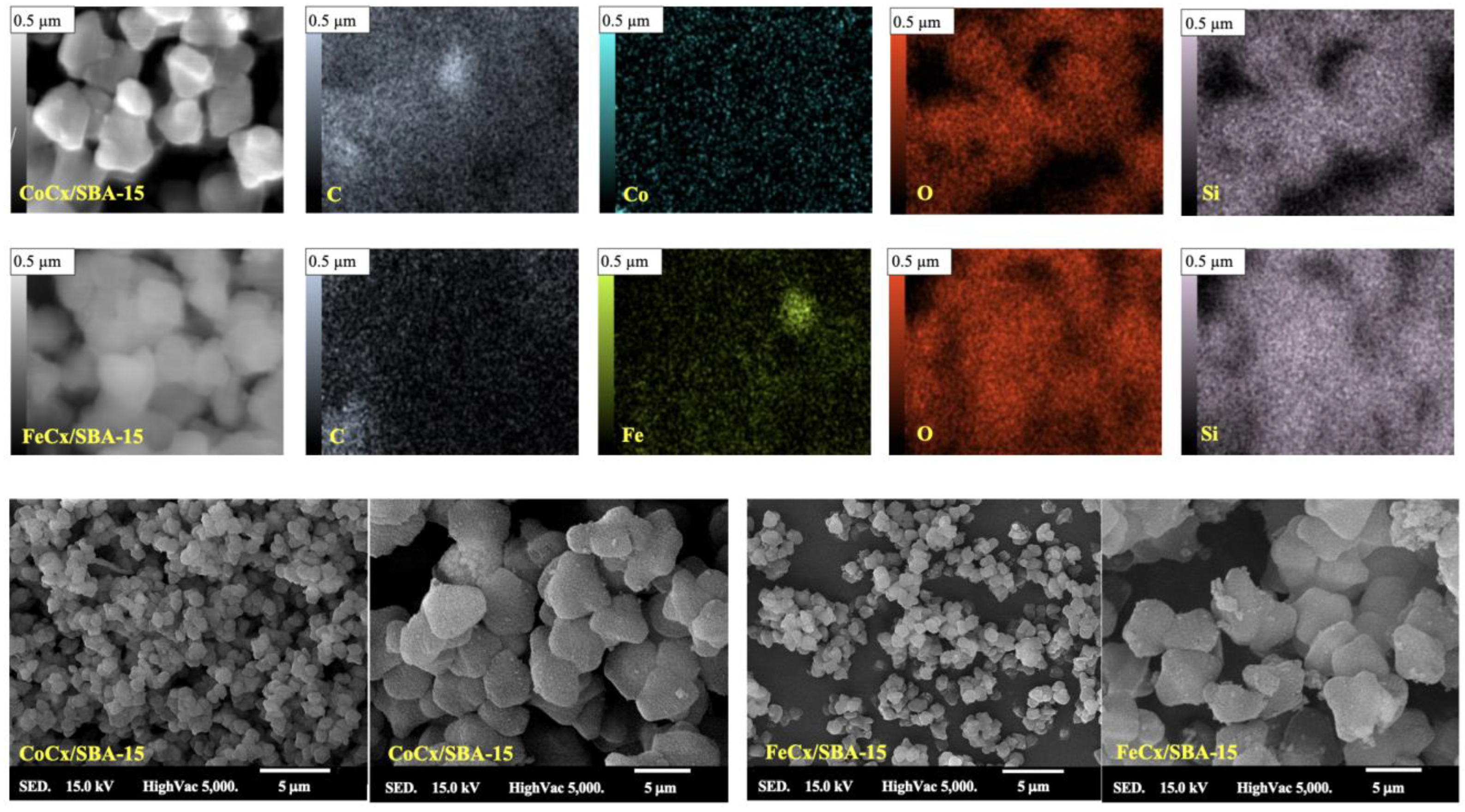
2.3.1. SEM
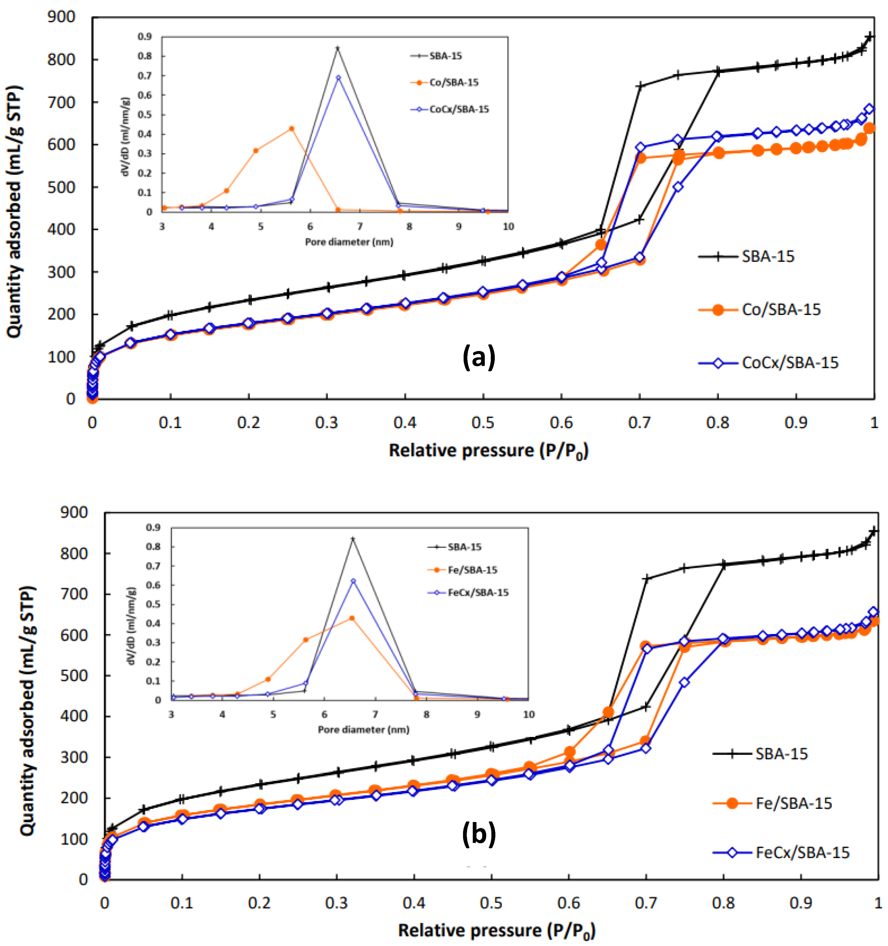
2.3.2. Nitrogen Adsorption–Desorption
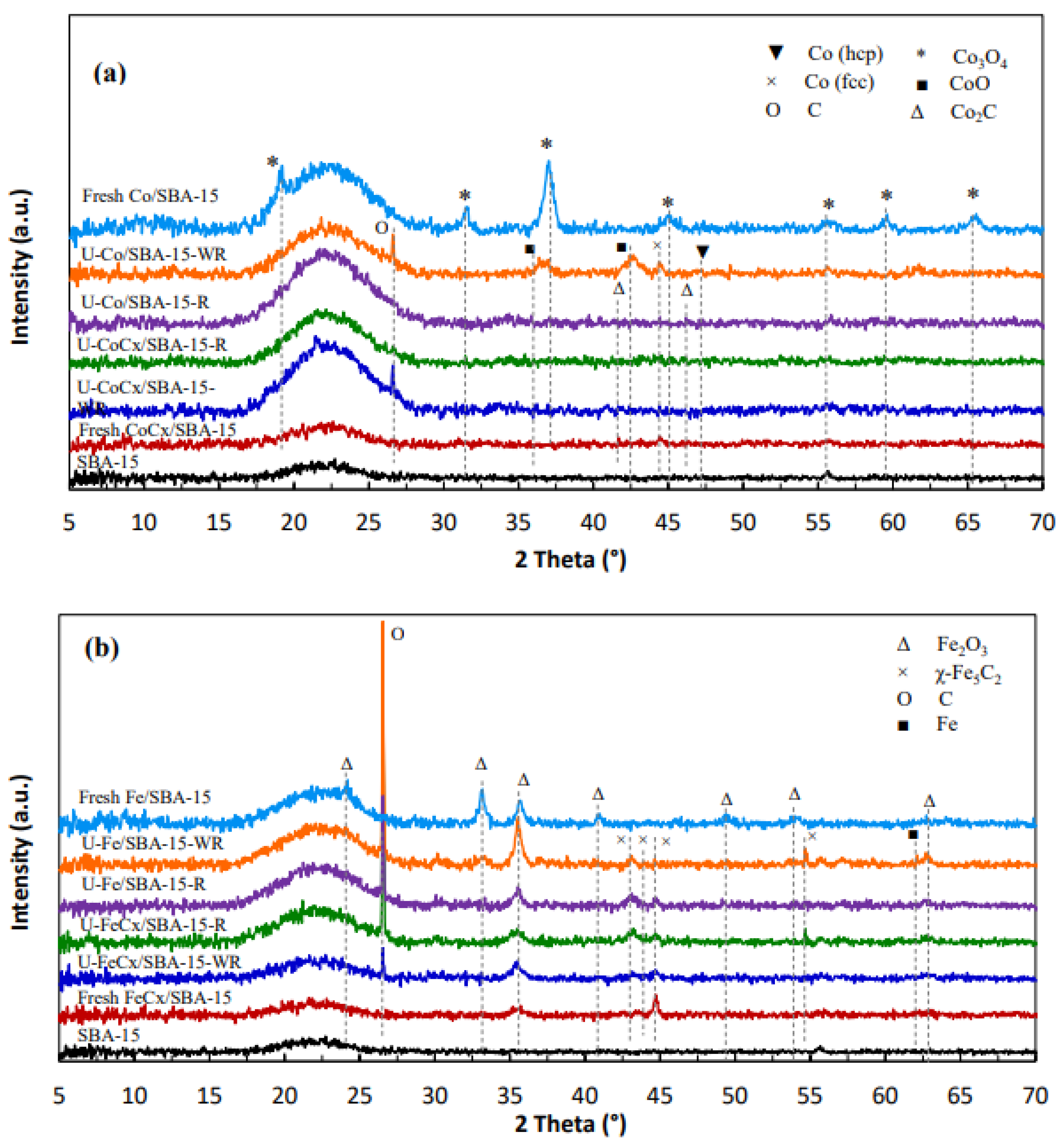
2.3.3. XRD
2.3.4. TGA
2.3.5. TGA Long-Term Analyses
2.3.6. ICP-OES
2.3.7. H2-TPR
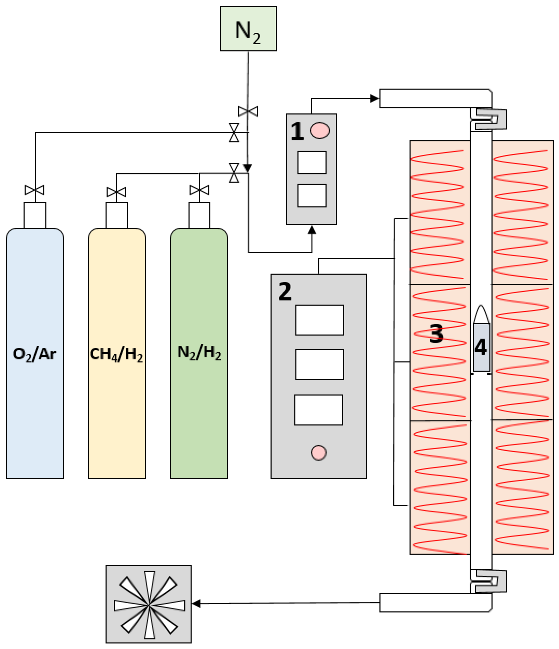
2.4. Experimental Reaction Setup
3. Results and Discussion
3.1. Characterization of Catalysts
3.1.1. SEM
3.1.2. Nitrogen Adsorption–Desorption
3.1.3. XRD
3.1.4. TGA
3.1.5. TGA Long-Term Analyses
3.1.6. ICP-OES
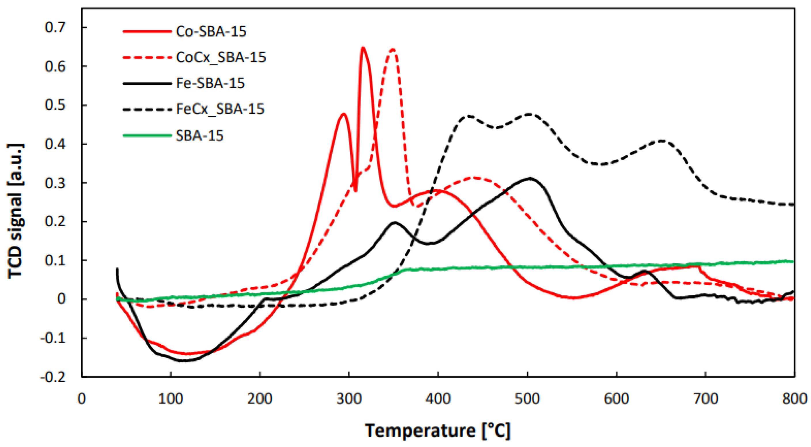
3.1.7. H2-TPR
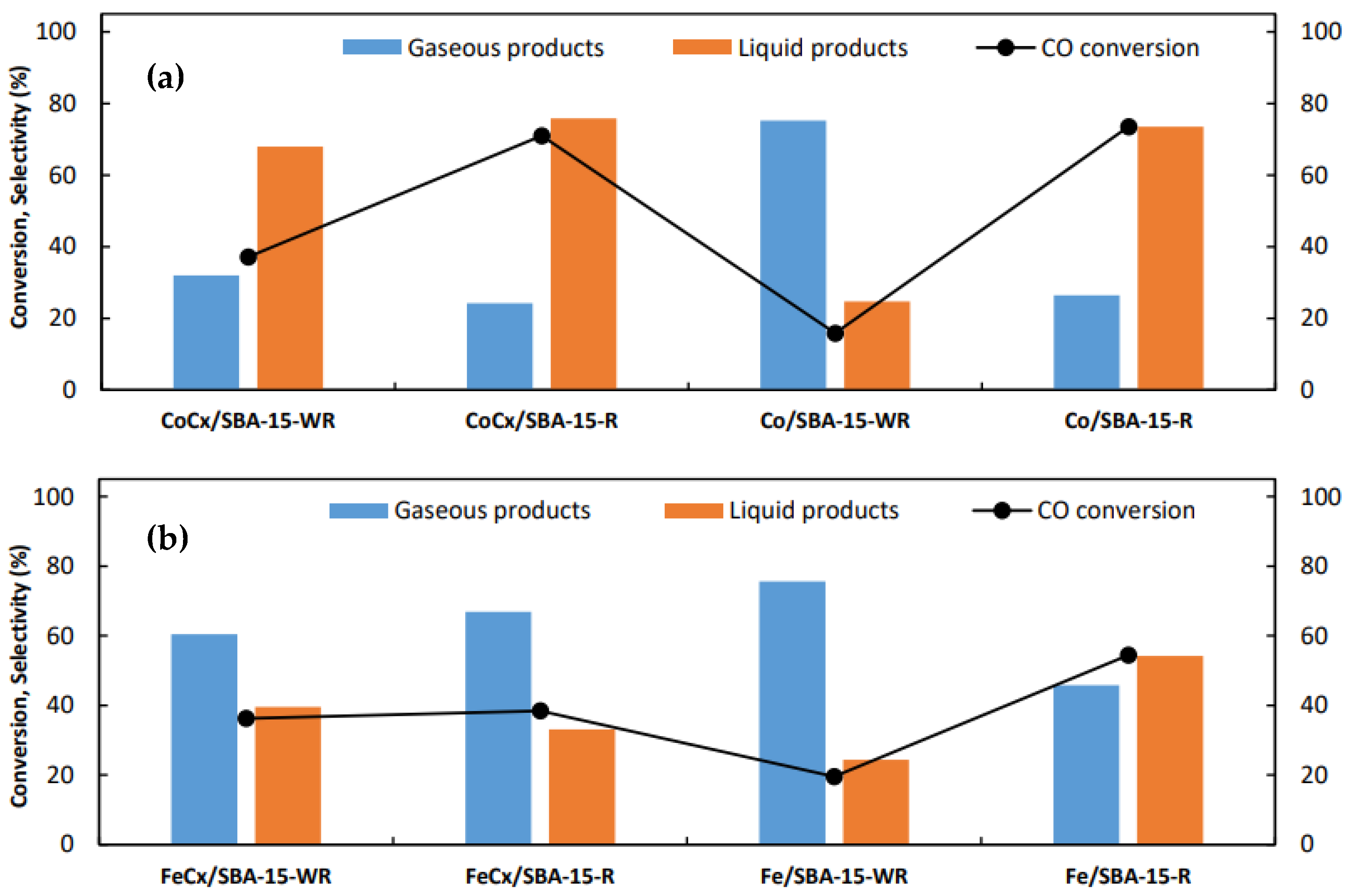
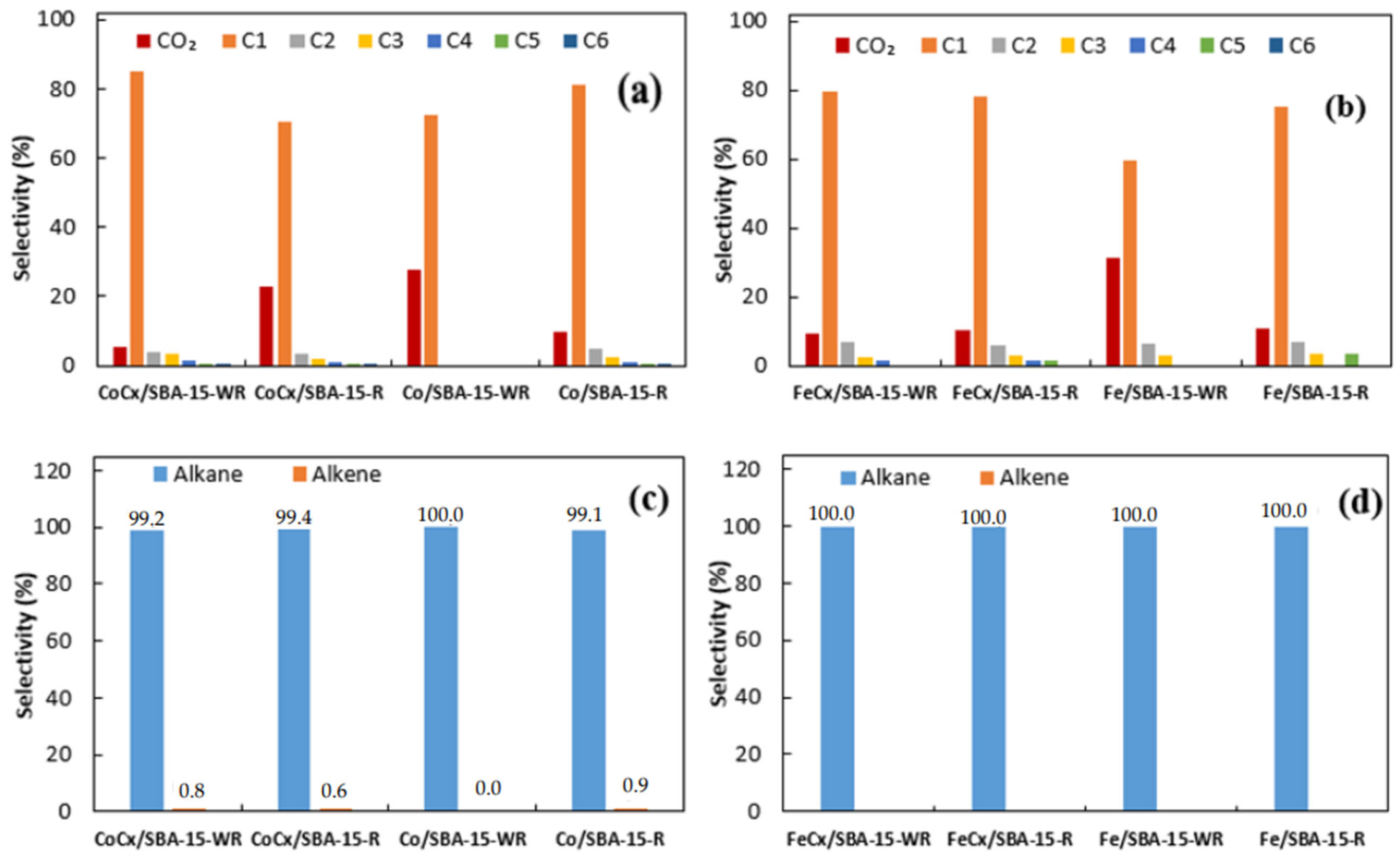
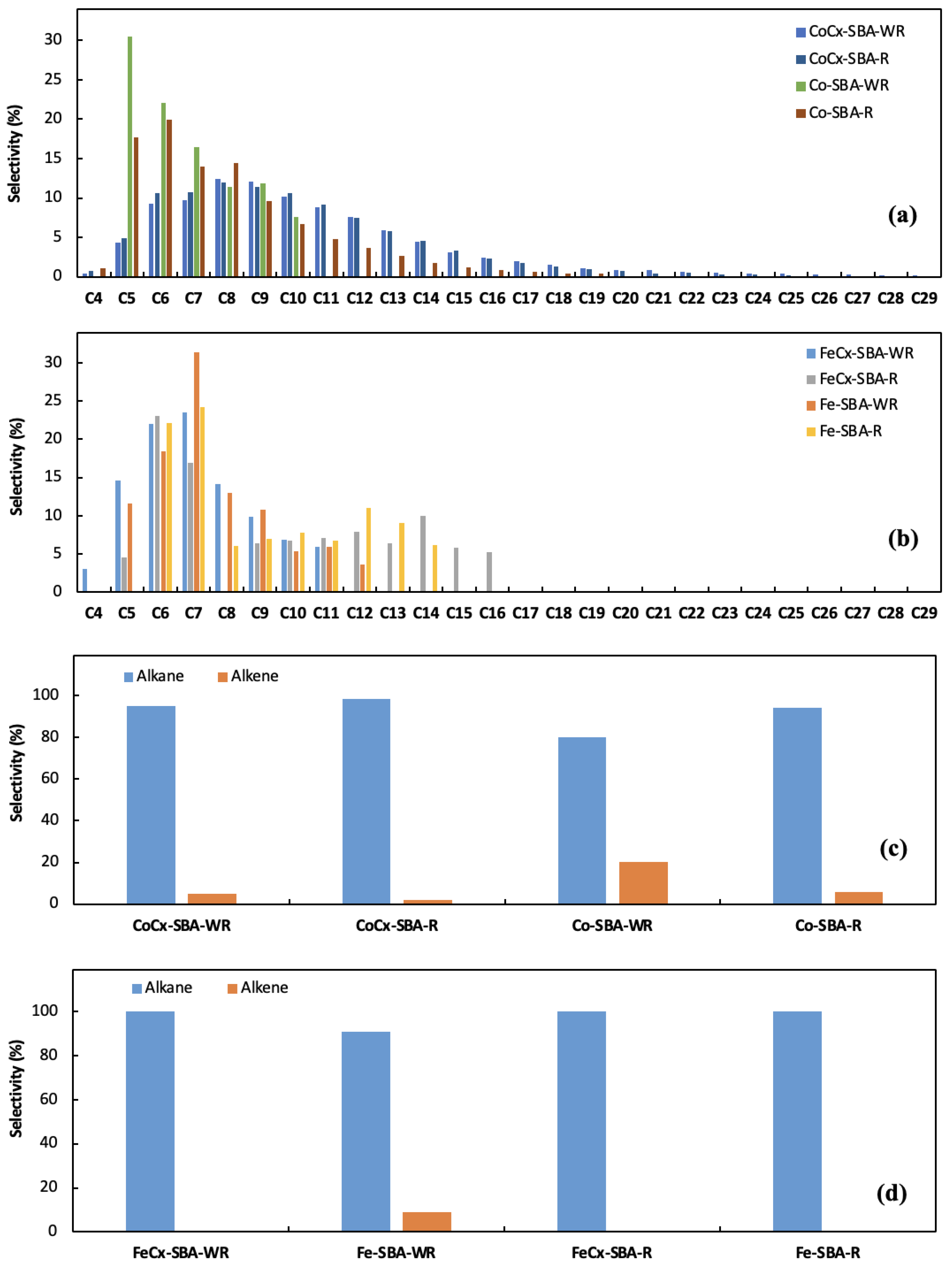
3.2. Catalytic Performance
4. Conclusions
Author Contributions
Funding
Data Availability Statement
Conflicts of Interest
References
- Saheli, S.; Rezvani, A.R.; Izadpanah, A.; Dusek, M.; Eigner, V. Design novel inorganic precursors for producing clean fuels by using Fischer-Tropsch synthesis. J. Saudi Chem. Soc. 2019, 23, 1070–1079. [Google Scholar] [CrossRef]
- Li, W.-Z.; Liu, J.-X.; Gu, J.; Zhou, W.; Yao, S.-Y.; Si, R.; Guo, Y.; Su, H.-Y.; Yan, C.-H.; Li, W.-X.; et al. Chemical Insights into the Design and Development of Face-Centered Cubic Ruthenium Catalysts for Fischer–Tropsch Synthesis. J. Am. Chem. Soc. 2017, 139, 2267–2276. [Google Scholar] [CrossRef]
- Sirikulbodee, P.; Ratana, T.; Sornchamni, T.; Phongaksorn, M.; Tungkamani, S. Catalytic performance of Iron-based catalyst in Fischer–Tropsch synthesis using CO2 containing syngas. Energy Procedia 2017, 138, 998–1003. [Google Scholar] [CrossRef]
- Gholami, Z.; Tišler, Z.; Rubáš, V. Recent advances in Fischer-Tropsch synthesis using cobalt-based catalysts: A review on supports, promoters, and reactors. Catal. Rev. 2020, 63, 512–595. [Google Scholar] [CrossRef]
- Lin, T.; Gong, K.; Wang, C.; An, Y.; Wang, X.; Qi, X.; Li, S.; Lu, Y.; Zhong, L.; Sun, Y. Fischer–Tropsch Synthesis to Olefins: Catalytic Performance and Structure Evolution of Co2C-Based Catalysts under a CO2 Environment. ACS Catal. 2019, 9, 9554–9567. [Google Scholar] [CrossRef]
- Xiang, Y.; Kruse, N. Tuning the catalytic CO hydrogenation to straight- and long-chain aldehydes/alcohols and olefins/paraffins. Nat. Commun. 2016, 7, 13058. [Google Scholar] [CrossRef] [PubMed]
- Yang, R.; Xia, Z.; Zhao, Z.; Sun, F.; Du, X.; Yu, H.; Gu, S.; Zhong, L.; Zhao, J.; Ding, Y.; et al. Characterization of CoMn catalyst by in situ X-ray absorption spectroscopy and wavelet analysis for Fischer–Tropsch to olefins reaction. J. Energy Chem. 2019, 32, 118–123. [Google Scholar] [CrossRef]
- Zhong, L.; Yu, F.; An, Y.; Zhao, Y.; Sun, Y.; Li, Z.; Lin, T.; Lin, Y.; Qi, X.; Dai, Y.; et al. Cobalt carbide nanoprisms for direct production of lower olefins from syngas. Nature 2016, 538, 84–87. [Google Scholar] [CrossRef]
- Gnanamani, M.K.; Jacobs, G.; Graham, U.M.; Ribeiro, M.C.; Noronha, F.B.; Shafer, W.D.; Davis, B.H. Influence of carbide formation on oxygenates selectivity during Fischer-Tropsch synthesis over Ce-containing Co catalysts. Catal. Today 2016, 261, 40–47. [Google Scholar] [CrossRef]
- Chen, P.-P.; Liu, J.-X.; Li, W.-X. Carbon Monoxide Activation on Cobalt Carbide for Fischer–Tropsch Synthesis from First-Principles Theory. ACS Catal. 2019, 9, 8093–8103. [Google Scholar] [CrossRef]
- Lebarbier, V.M.; Mei, D.; Kim, D.H.; Andersen, A.; Male, J.L.; Holladay, J.E.; Rousseau, R.; Wang, Y. Effects of La2O3 on the Mixed Higher Alcohols Synthesis from Syngas over Co Catalysts: A Combined Theoretical and Experimental Study. J. Phys. Chem. C 2011, 115, 17440–17451. [Google Scholar] [CrossRef]
- Pei, Y.-P.; Liu, J.-X.; Zhao, Y.-H.; Ding, Y.-J.; Liu, T.; Dong, W.-D.; Zhu, H.-J.; Su, H.-Y.; Yan, L.; Li, J.-L.; et al. High Alcohols Synthesis via Fischer–Tropsch Reaction at Cobalt Metal/Carbide Interface. ACS Catal. 2015, 5, 3620–3624. [Google Scholar] [CrossRef]
- Zhang, S.; Liu, X.; Shao, Z.; Wang, H.; Sun, Y. Direct CO2 hydrogenation to ethanol over supported Co2C catalysts: Studies on support effects and mechanism. J. Catal. 2020, 382, 86–96. [Google Scholar] [CrossRef]
- Dai, Y.; Zhao, Y.; Lin, T.; Li, S.; Yu, F.; An, Y.; Wang, X.; Xiao, K.; Sun, F.; Jiang, Z.; et al. Particle Size Effects of Cobalt Carbide for Fischer–Tropsch to Olefins. ACS Catal. 2018, 9, 798–809. [Google Scholar] [CrossRef]
- Zhao, D.; Feng, J.; Huo, Q.; Melosh, N.; Fredrickson, G.H.; Chmelka, B.F.; Stucky, G.D. Triblock Copolymer Syntheses of Mesoporous Silica with Periodic 50 to 300 Angstrom Pores. Science 1998, 279, 548–552. [Google Scholar] [CrossRef] [PubMed]
- Dancuart, L.P.; de Haan, R.; de Klerk, A. Processing of Primary Fischer-Tropsch Products. In Studies in Surface Science and Catalysis; Elsevier: Amsterdam, The Netherlands, 2004; Volume 152, Chapter 6; pp. 482–532. [Google Scholar] [CrossRef]
- Trofimova, E.Y.; Kurdyukov, D.A.; Kukushkina, Y.A.; Yagovkina, M.A.; Golubev, V.G. Synthesis of monodispersed mesoporous spheres of submicron size amorphous silica. Glass Phys. Chem. 2011, 37, 378–384. [Google Scholar] [CrossRef]
- Zhao, D.; Sun, J.; Li, Q.; Stucky, G.D. Morphological Control of Highly Ordered Mesoporous Silica SBA-15. Chem. Mater. 2000, 12, 275–279. [Google Scholar] [CrossRef]
- Lu, Q.; Wang, Z.; Li, J.; Wang, P.; Ye, X. Structure and Photoluminescent Properties of ZnO Encapsulated in Mesoporous Silica SBA-15 Fabricated by Two-Solvent Strategy. Nanoscale Res. Lett. 2009, 4, 646–654. [Google Scholar] [CrossRef]
- Zukal, A.; Siklová, H.; Cejka, J. Grafting of Alumina on SBA-15: Effect of Surface Roughness. Langmuir 2008, 24, 9837–9842. [Google Scholar] [CrossRef]
- Gholami, Z.; Tišler, Z.; Svobodová, E.; Hradecká, I.; Sharkov, N.; Gholami, F. Catalytic Performance of Alumina-Supported Cobalt Carbide Catalysts for Low-Temperature Fischer–Tropsch Synthesis. Catalysts 2022, 12, 1222. [Google Scholar] [CrossRef]
- Sing, K. Reporting physisorption data for gas/solid systems with special reference to the determination of surface area and porosity (Provisional). Pure Appl. Chem. 1982, 54, 2201–2218. [Google Scholar] [CrossRef]
- Thommes, M.; Kaneko, K.; Neimark, A.V.; Olivier, J.P.; Rodriguez-Reinoso, F.; Rouquerol, J.; Sing, K.S. Physisorption of gases, with special reference to the evaluation of surface area and pore size distribution (IUPAC Technical Report). Pure Appl. Chem. 2015, 87, 1051–1069. [Google Scholar] [CrossRef]
- Fan, X.; Li, J.; Zhao, Z.; Wei, Y.; Liu, J.; Duan, A.; Jiang, G. Dehydrogenation of propane over PtSn/SBA-15 catalysts: Effect of the amount of metal loading and state. RSC Adv. 2015, 5, 28305–28315. [Google Scholar] [CrossRef]
- Yao, Q.; Lu, Z.-H.; Yang, K.; Chen, X.; Zhu, M. Ruthenium nanoparticles confined in SBA-15 as highly efficient catalyst for hydrolytic dehydrogenation of ammonia borane and hydrazine borane. Sci. Rep. 2015, 5, 15186. [Google Scholar] [CrossRef]
- Ding, M.; Yang, Y.; Wu, B.; Li, Y.; Wang, T.; Ma, L. Study on reduction and carburization behaviors of iron phases for iron-based Fischer–Tropsch synthesis catalyst. Appl. Energy 2015, 160, 982–989. [Google Scholar] [CrossRef]
- Mogorosi, R.P.; Fischer, N.; Claeys, M.; van Steen, E. Strong-metal–support interaction by molecular design: Fe–silicate interactions in Fischer–Tropsch catalysts. J. Catal. 2012, 289, 140–150. [Google Scholar] [CrossRef]
- Abelló, S.; Montané, D. Exploring Iron-based Multifunctional Catalysts for Fischer–Tropsch Synthesis: A Review. ChemSusChem 2011, 4, 1538–1556. [Google Scholar] [CrossRef] [PubMed]
- Ribeiro, M.C.; Jacobs, G.; Davis, B.H.; Cronauer, D.C.; Kropf, A.J.; Marshall, C.L. Fischer−Tropsch Synthesis: An In-Situ TPR-EXAFS/XANES Investigation of the Influence of Group I Alkali Promoters on the Local Atomic and Electronic Structure of Carburized Iron/Silica Catalysts. J. Phys. Chem. C 2010, 114, 7895–7903. [Google Scholar] [CrossRef]
- Bian, G.; Oonuki, A.; Koizumi, N.; Nomoto, H.; Yamada, M. Studies with a precipitated iron Fischer-Tropsch catalyst reduced by H2 or CO. J. Mol. Catal. A Chem. 2002, 186, 203–213. [Google Scholar] [CrossRef]
- Mohandas, J.C.; Gnanamani, M.K.; Jacobs, G.; Ma, W.; Ji, Y.; Khalid, S.; Davis, B.H. Fischer–Tropsch Synthesis: Characterization and Reaction Testing of Cobalt Carbide. ACS Catal. 2011, 1, 1581–1588. [Google Scholar] [CrossRef]
- Moya-Cancino, J.G.; Honkanen, A.-P.; van der Eerden, A.M.J.; Oord, R.; Monai, M.; ten Have, I.; Sahle, C.J.; Meirer, F.; Weckhuysen, B.M.; de Groot, F.M.F.; et al. In Situ X-ray Raman Scattering Spectroscopy of the Formation of Cobalt Carbides in a Co/TiO2 Fischer–Tropsch Synthesis Catalyst. ACS Catal. 2021, 11, 809–819. [Google Scholar] [CrossRef]
- Lin, Q.; Liu, B.; Jiang, F.; Fang, X.; Xu, Y.; Liu, X. Assessing the formation of cobalt carbide and its catalytic performance under realistic reaction conditions and tuning product selectivity in a cobalt-based FTS reaction. Catal. Sci. Technol. 2019, 9, 3238–3258. [Google Scholar] [CrossRef]
- Liu, J.-X.; Su, H.-Y.; Sun, D.-P.; Zhang, B.-Y.; Li, W.-X. Crystallographic Dependence of CO Activation on Cobalt Catalysts: HCP versus FCC. J. Am. Chem. Soc. 2013, 135, 16284–16287. [Google Scholar] [CrossRef] [PubMed]
- Ten Have, I.C.; Weckhuysen, B.M. The active phase in cobalt-based Fischer-Tropsch synthesis. Chem Catal. 2021, 1, 339–363. [Google Scholar] [CrossRef]
- Lyu, S.; Wang, L.; Zhang, J.; Liu, C.; Sun, J.; Peng, B.; Wang, Y.; Rappé, K.G.; Zhang, Y.; Li, J.; et al. Role of Active Phase in Fischer–Tropsch Synthesis: Experimental Evidence of CO Activation over Single-Phase Cobalt Catalysts. ACS Catal. 2018, 8, 7787–7798. [Google Scholar] [CrossRef]
- Xiao, Y.; Sun, P.; Cao, M. Core–Shell Bimetallic Carbide Nanoparticles Confined in a Three-Dimensional N-Doped Carbon Conductive Network for Efficient Lithium Storage. ACS Nano 2014, 8, 7846–7857. [Google Scholar] [CrossRef]
- Lin, T.; Yu, F.; An, Y.; Qin, T.; Li, L.; Gong, K.; Zhong, L.; Sun, Y. Cobalt Carbide Nanocatalysts for Efficient Syngas Conversion to Value-Added Chemicals with High Selectivity. Acc. Chem. Res. 2021, 54, 1961–1971. [Google Scholar] [CrossRef]
- An, Y.; Lin, T.; Yu, F.; Wang, X.; Lu, Y.; Zhong, L.; Wang, H.; Sun, Y. Effect of Reaction Pressures on Structure–Performance of Co2C-Based Catalyst for Syngas Conversion. Ind. Eng. Chem. Res. 2018, 57, 15647–15653. [Google Scholar] [CrossRef]
- Choi, Y.I.; Yang, J.H.; Park, S.J.; Sohn, Y. Energy Storage and CO2 Reduction Performances of Co/Co2C/C Prepared by an Anaerobic Ethanol Oxidation Reaction Using Sacrificial SnO2. Catalysts 2020, 10, 1116. [Google Scholar] [CrossRef]
- Dry, M.E. Fischer-Tropsch synthesis over iron catalysts. Catal. Lett. 1990, 7, 241–251. [Google Scholar] [CrossRef]
- Davis, B.H. Fischer−Tropsch Synthesis: Comparison of Performances of Iron and Cobalt Catalysts. Ind. Eng. Chem. Res. 2007, 46, 8938–8945. [Google Scholar] [CrossRef]
- Khodakov, A.Y.; Chu, W.; Fongarland, P. Advances in the Development of Novel Cobalt Fischer−Tropsch Catalysts for Synthesis of Long-Chain Hydrocarbons and Clean Fuels. Chem. Rev. 2007, 107, 1692–1744. [Google Scholar] [CrossRef] [PubMed]
- Wang, D.; Chen, B.; Duan, X.; Chen, D.; Zhou, X. Iron-based Fischer–Tropsch synthesis of lower olefins: The nature of χ-Fe5C2 catalyst and why and how to introduce promoters. J. Energy Chem. 2016, 25, 911–916. [Google Scholar] [CrossRef]
- Chen, B.; Wang, D.; Duan, X.; Liu, W.; Li, Y.; Qian, G.; Yuan, W.; Holmen, A.; Zhou, X.; Chen, D. Charge-Tuned CO Activation over a χ-Fe5C2 Fischer–Tropsch Catalyst. ACS Catal. 2018, 8, 2709–2714. [Google Scholar] [CrossRef]
- Chang, Q.; Zhang, C.; Liu, C.; Wei, Y.; Cheruvathur, A.V.; Dugulan, A.I.; Niemantsverdriet, J.W.; Liu, X.; He, Y.; Qing, M.; et al. Relationship between Iron Carbide Phases (ε-Fe2C, Fe7C3, and χ-Fe5C2) and Catalytic Performances of Fe/SiO2 Fischer–Tropsch Catalysts. ACS Catal. 2018, 8, 3304–3316. [Google Scholar] [CrossRef]
- Zhang, C.-H.; Wan, H.-J.; Yang, Y.; Xiang, H.-W.; Li, Y.-W. Study on the iron–silica interaction of a co-precipitated Fe/SiO2 Fischer–Tropsch synthesis catalyst. Catal. Commun. 2006, 7, 733–738. [Google Scholar] [CrossRef]
- Yin, J.; He, Y.; Liu, X.; Zhou, X.; Huo, C.F.; Guo, W.; Peng, Q.; Yang, Y.; Jiao, H.; Li, Y.W.; et al. Visiting CH4 formation and C1 + C1 couplings to tune CH4 selectivity on Fe surfaces. J. Catal. 2019, 372, 217–225. [Google Scholar] [CrossRef]


| Catalyst | BET Surface Area (m2/g) | Total Pore Volume (cm3/g) |
|---|---|---|
| SBA-15 | 842 | 1.23 |
| Co/SBA-15 | 624 | 0.93 |
| Fe/SBA-15 | 649 | 0.91 |
| CoCx/SBA-15 | 665 | 1.05 |
| FeCx/SBA-15 | 679 | 1.05 |
| Catalyst | Co (wt.%) | Fe (wt.%) | C (wt.%) | SiO2 (wt.%) |
|---|---|---|---|---|
| Co/SBA-15 | 4.18 | - | <0.06 | 86.6 |
| Fe/SBA-15 | - | 3.79 | <0.06 | 90.4 |
| CoCx/SBA-15 | 3.97 | - | <0.06 | 91.4 |
| FeCx/SBA-15 | - | 3.64 | <0.06 | 84.8 |
Disclaimer/Publisher’s Note: The statements, opinions and data contained in all publications are solely those of the individual author(s) and contributor(s) and not of MDPI and/or the editor(s). MDPI and/or the editor(s) disclaim responsibility for any injury to people or property resulting from any ideas, methods, instructions or products referred to in the content. |
© 2023 by the authors. Licensee MDPI, Basel, Switzerland. This article is an open access article distributed under the terms and conditions of the Creative Commons Attribution (CC BY) license (https://creativecommons.org/licenses/by/4.0/).
Share and Cite
Sharkov, N.; Gholami, Z.; Hradecká, I.; Tišler, Z.; Šimek, J. Product Yields Dependency on the Carbide Phase Presence in Cobalt and Iron SBA-15 Catalysts Structure in the Fischer–Tropsch Synthesis. Processes 2023, 11, 1391. https://doi.org/10.3390/pr11051391
Sharkov N, Gholami Z, Hradecká I, Tišler Z, Šimek J. Product Yields Dependency on the Carbide Phase Presence in Cobalt and Iron SBA-15 Catalysts Structure in the Fischer–Tropsch Synthesis. Processes. 2023; 11(5):1391. https://doi.org/10.3390/pr11051391
Chicago/Turabian StyleSharkov, Nikita, Zahra Gholami, Ivana Hradecká, Zdeněk Tišler, and Josef Šimek. 2023. "Product Yields Dependency on the Carbide Phase Presence in Cobalt and Iron SBA-15 Catalysts Structure in the Fischer–Tropsch Synthesis" Processes 11, no. 5: 1391. https://doi.org/10.3390/pr11051391
APA StyleSharkov, N., Gholami, Z., Hradecká, I., Tišler, Z., & Šimek, J. (2023). Product Yields Dependency on the Carbide Phase Presence in Cobalt and Iron SBA-15 Catalysts Structure in the Fischer–Tropsch Synthesis. Processes, 11(5), 1391. https://doi.org/10.3390/pr11051391