

Review of CFD-DEM Modeling of Wet Fluidized Bed Granulation and Coating Processes


Abstract
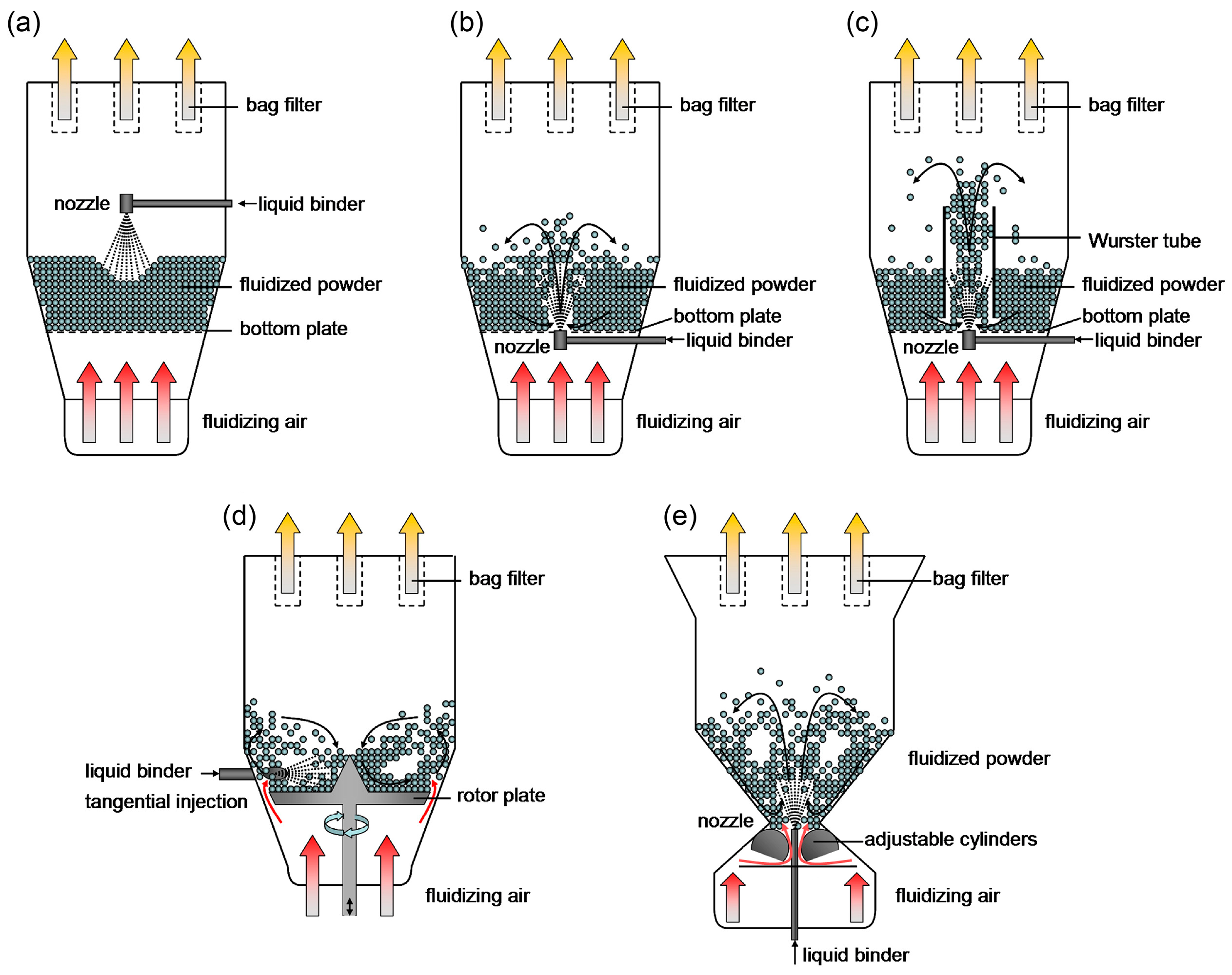
1. Introduction

2. Governing Equations
2.1. CFD
2.2. DEM
3. Force Calculation
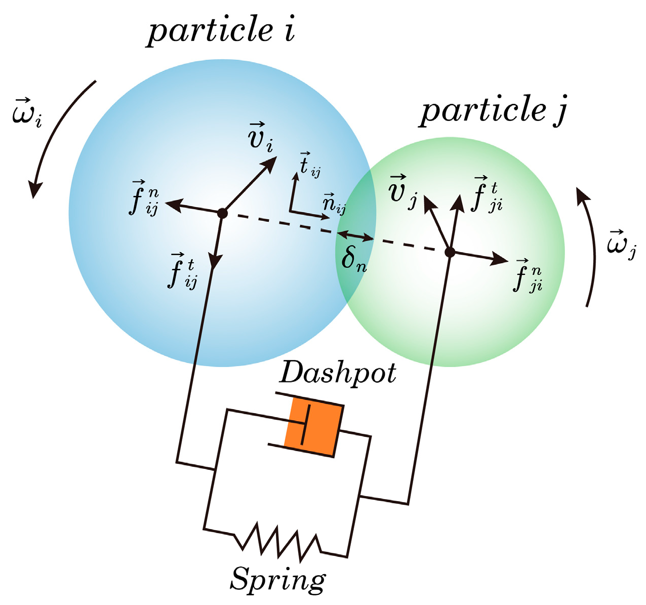
3.1. Contact Forces
3.2. Non-Contact Forces

3.3. Gas-Solid Interaction Forces
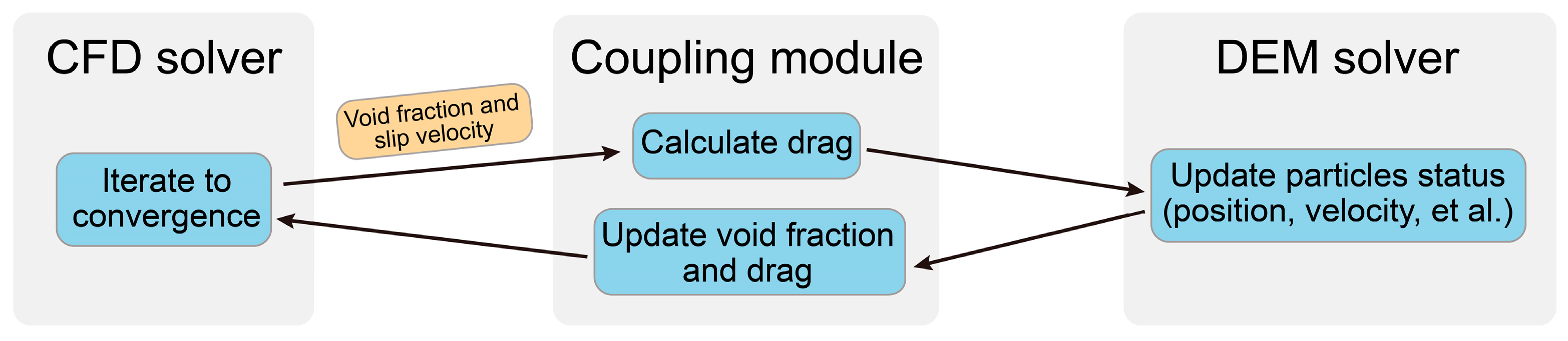
4. Coupling Schemes
5. Research Focus and the Role of CFD-DEM
6. Conclusions and Outlook
Author Contributions
Funding
Institutional Review Board Statement
Informed Consent Statement
Data Availability Statement
Conflicts of Interest
Nomenclature
| drag coefficient | |
| diameter of a particle | |
| normal contact force between particle i and j | |
| tangential contact force between particle i and j | |
| local averaged force on particle i exerted by the surrounding fluid | |
| local averaged particle-fluid interaction force arising from the velocity fluctuations as fluid passes around the particles or through the interstices among the particles | |
| volume-averaged fluid-solid interaction forces in Model A | |
| volume-averaged fluid-solid interaction forces in Model B | |
| total contact force on particle i | |
| interaction force with the surrounding fluid | |
| total non-contact force on particle i | |
| gravitational acceleration | |
| moment of inertia of particle i | |
| mass of particle i | |
| unit vector on the normal direction of particle i and j | |
| pressure of gas phase | |
| radius of particle i | |
| radius of particle j | |
| Reynolds number of particle i | |
| unit vector on the tangential direction of particle i and j | |
| total torque on particle i | |
| fluid velocity | |
| solid velocity | |
| velocity of particle i | |
| velocity of particle j | |
| relative velocity at the contact point of particle i and j | |
| normal component of | |
| tangential component of | |
| Greek Letters | |
| interphase momentum exchange coefficient | |
| normal displacement of particle i and j | |
| tangential displacement of particle i and j | |
| volume fraction of fluid phase | |
| volume fraction of solid phase | |
| normal damping coefficient | |
| tangential damping coefficient | |
| coefficient of sliding friction between particle i and j | |
| dynamic viscosity of fluid phase | |
| angular velocity of particle i | |
| angular velocity of particle j | |
| fluid density | |
| viscous stress tensor of fluid phase | |
| stress tensor of solid phase | |
| Superscripts & Subscripts | |
| con | contact |
| d | drag |
| eff | effective |
| f | fluid |
| g | gas |
| i, j | particle index |
| n | normal direction |
| p | particle |
| s | solid |
| t | tangential direction |
References
- Thapa, P.; Tripathi, J.; Jeong, S.H. Recent trends and future perspective of pharmaceutical wet granulation for better process understanding and product development. Powder Technol. 2019, 344, 864–882. [Google Scholar] [CrossRef]
- Chen, P.; Ansari, M.J.; Bokov, D.; Suksatan, W.; Rahman, M.L.; Sarjadi, M.S. A review on key aspects of wet granulation process for continuous pharmaceutical manufacturing of solid dosage oral formulations. Arab. J. Chem. 2022, 15, 103598. [Google Scholar] [CrossRef]
- Alobaid, F.; Almohammed, N.; Massoudi Farid, M.; May, J.; Rößger, P.; Richter, A.; Epple, B. Progress in CFD Simulations of Fluidized Beds for Chemical and Energy Process Engineering. Prog. Energy Combust. Sci. 2022, 91, 100930. [Google Scholar]
- Abourabia, A.M.; Morad, A.M. Exact traveling wave solutions of the van der Waals normal form for fluidized granular matter. Physica 2015, 437, 333–350. [Google Scholar] [CrossRef]
- Morad, A.M.; Selima, E.S.; Abu-Nab, A.K. Bubbles interactions in fluidized granular medium for the van der Waals hydrodynamic regime. Eur. Phys. J. Plus 2021, 136, 306. [Google Scholar] [CrossRef]
- Abourabia, A.M.; El-Danaf, T.S.; Morad, A.M. Exact solutions of the hierarchical Korteweg–de Vries equation of microstructured granular materials. Chaos Solitons Fractals 2009, 41, 716–726. [Google Scholar] [CrossRef]
- Abourabia, A.M.; Hassan, K.M.; Morad, A.M. Analytical solutions of the magma equations for molten rocks in a granular matrix. Chaos Solitons Fractals 2009, 42, 1170–1180. [Google Scholar] [CrossRef]
- Depypere, F.; Pieters, J.G.; Dewettinck, K. PEPT visualisation of particle motion in a tapered fluidised bed coater. J. Food Eng. 2009, 93, 324–336. [Google Scholar] [CrossRef]
- Li, L.; Rasmuson, A.; Ingram, A.; Johansson, M.; Remmelgas, J.; von Corswant, C.; Folestad, S. PEPT study of particle cycle and residence time distributions in a Wurster fluid bed. AIChE J. 2014, 61, 756–768. [Google Scholar] [CrossRef]
- Zhang, R.; Hoffmann, T.; Tsotsas, E. Novel Technique for Coating of Fine Particles Using Fluidized Bed and Aerosol Atomizer. Processes 2020, 8, 1525. [Google Scholar] [CrossRef]
- Karlsson, S.; Niklasson Björn, I.; Folestad, S.; Rasmuson, A. Measurement of the particle movement in the fountain region of a Wurster type bed. Powder Technol. 2006, 165, 22–29. [Google Scholar] [CrossRef]
- Waldie, B.; Wilkinson, D. Measurement of particle movement in a spouted bed using a new microprocessor based technique. Can. J. Chem. Eng. 1986, 64, 944–949. [Google Scholar] [CrossRef]
- Ge, R.; Ye, J.; Wang, H.; Yang, W. Measurement of particle concentration in a Wurster fluidized bed by electrical capacitance tomography sensors. AIChE J. 2014, 60, 4051–4064. [Google Scholar] [CrossRef]
- Buist, K.A.; Jayaprakash, P.; Kuipers, J.A.M.; Deen, N.G.; Padding, J.T. Magnetic particle tracking for nonspherical particles in a cylindrical fluidized bed. AIChE J. 2017, 63, 5335–5342. [Google Scholar] [CrossRef]
- Palmer, S.; Ingram, A.; Fan, X.; Fitzpatrick, S.; Seville, J. Investigation of the sources of variability in the Wurster coater: Analysis of particle cycle times using PEPT. In Proceedings of the 12th International Conference on Fluidization-New Horizons in Fluidization Engineering, Vancouver, BC, Canada, 13–17 May 2007. [Google Scholar]
- Grohn, P.; Oesau, T.; Heinrich, S.; Antonyuk, S. Investigation of the influence of wetting on the particle dynamics in a fluidized bed rotor granulator by MPT measurements and CFD-DEM simulations. Powder Technol. 2022, 408, 117736. [Google Scholar] [CrossRef]
- Zhou, H.; Tu, Q.Y.; Wang, H.G. Investigation of the complex gas-solids flow characteristics in a fluidized bed with a Wurster tube by process tomography and CFD simulation. Powder Technol. 2019, 357, 117–133. [Google Scholar] [CrossRef]
- Che, H.; Ye, J.; Tu, Q.; Yang, W.; Wang, H. Investigation of coating process in Wurster fluidised bed using electrical capacitance tomography. Chem. Eng. Res. Des. 2018, 132, 1180–1192. [Google Scholar] [CrossRef]
- Laverman, J.A.; Roghair, I.; Annaland, M.V.S.; Kuipers, H. Investigation into the hydrodynamics of gas–solid fluidized beds using particle image velocimetry coupled with digital image analysis. Can. J. Chem. Eng. 2008, 86, 523–535. [Google Scholar] [CrossRef]
- Hemamanjushree, S.; Tippavajhala, V.K. Simulation of Unit Operations in Formulation Development of Tablets Using Computational Fluid Dynamics. AAPS PharmSciTech 2020, 21. [Google Scholar] [CrossRef]
- Kieckhefen, P.; Lichtenegger, T.; Pietsch, S.; Pirker, S.; Heinrich, S. Simulation of spray coating in a spouted bed using recurrence CFD. Particuology 2019, 42, 92–103. [Google Scholar] [CrossRef]
- Li, H.; Liu, D.; Ma, J.; Chen, X. Simulation of a Wurster fluidized bed by CFD–DEM with a cohesive contact model. Chem. Eng. Res. Des. 2022, 177, 157–166. [Google Scholar] [CrossRef]
- Li, L.; Remmelgas, J.; van Wachem, B.G.; von Corswant, C.; Johansson, M.; Folestad, S.; Rasmuson, A. Residence time distributions of different size particles in the spray zone of a Wurster fluid bed studied using DEM-CFD. Powder Technol. 2015, 280, 124–134. [Google Scholar] [CrossRef]
- Madlmeir, S.; Forgber, T.; Trogrlic, M.; Jajcevic, D.; Kape, A.; Contreras, L.; Carmody, A.; Liu, P.; Davies, C.; Sarkar, A.; et al. Quantifying the coating yield by modeling heat and mass transfer in a Wurster fluidized bed coater. Chem. Eng. Sci. 2022, 252, 117505. [Google Scholar] [CrossRef]
- Kieckhefen, P.; Pietsch-Braune, S.; Heinrich, S. Product-Property Guided Scale-Up of a Fluidized Bed Spray Granulation Process Using the CFD-DEM Method. Processes 2022, 10, 1291. [Google Scholar] [CrossRef]
- Ketterhagen, W.R.; Am Ende, M.T.; Hancock, B.C. Process modeling in the pharmaceutical industry using the discrete element method. J. Pharm. Sci. 2009, 98, 442–470. [Google Scholar] [CrossRef]
- Xu, B.H.; Yu, A.B. Numerical simulation of the gas-solid flow in a fluidized bed by combining discrete particle method with computational fluid dynamics. Chem. Eng. Sci. 1997, 52, 2785–2809. [Google Scholar] [CrossRef]
- Sutkar, V.S.; Deen, N.G.; Mohan, B.; Salikov, V.; Antonyuk, S.; Heinrich, S.; Kuipers, J.A.M. Numerical investigations of a pseudo-2D spout fluidized bed with draft plates using a scaled discrete particle model. Chem. Eng. Sci. 2013, 104, 790–807. [Google Scholar] [CrossRef]
- Barrasso, D.; Eppinger, T.; Pereira, F.E.; Aglave, R.; Debus, K.; Bermingham, S.K.; Ramachandran, R. A multi-scale, mechanistic model of a wet granulation process using a novel bi-directional PBM–DEM coupling algorithm. Chem. Eng. Sci. 2015, 123, 500–513. [Google Scholar] [CrossRef]
- Fries, L.; Dosta, M.; Antonyuk, S.; Heinrich, S.; Palzer, S. Moisture Distribution in Fluidized Beds with Liquid Injection. Chem. Eng. Technol. 2011, 34, 1076–1084. [Google Scholar] [CrossRef]
- Madlmeir, S.; Forgber, T.; Trogrlic, M.; Jajcevic, D.; Kape, A.; Contreras, L.; Carmody, A.; Liu, P.; Davies, C.; Sarkar, A.; et al. Modeling the coating layer thickness in a pharmaceutical coating process. Eur. J. Pharm. Sci. 2021, 161, 105770. [Google Scholar] [CrossRef]
- Jiang, Z.; Rieck, C.; Bück, A.; Tsotsas, E. Modeling of inter- and intra-particle coating uniformity in a Wurster fluidized bed by a coupled CFD-DEM-Monte Carlo approach. Chem. Eng. Sci. 2020, 211, 115289. [Google Scholar] [CrossRef]
- Jajcevic, D.; Siegmann, E.; Radeke, C.; Khinast, J.G. Large-scale CFD–DEM simulations of fluidized granular systems. Chem. Eng. Sci. 2013, 98, 298–310. [Google Scholar] [CrossRef]
- Zhao, Y.; Jiang, M.; Liu, Y.; Zheng, J. Particle-scale simulation of the flow and heat transfer behaviors in fluidized bed with immersed tube. AIChE J. 2009, 55, 3109–3124. [Google Scholar] [CrossRef]
- Foroughi-Dahr, M.; Sotudeh-Gharebagh, R.; Mostoufi, N. On the stability of Würster fluid bed of pharmaceutical pellets. Particuology 2019, 45, 81–90. [Google Scholar] [CrossRef]
- Šibanc, R.; Srčič, S.; Dreu, R. Numerical simulation of two-phase flow in a Wurster coating chamber and comparison with experimental results. Chem. Eng. Sci. 2013, 99, 225–237. [Google Scholar] [CrossRef]
- Zhang, W.; Wang, H.; You, C. Numerical simulation of fluidized bed coating process considering particle abrasion. Chem. Eng. J. 2022, 445, 136632. [Google Scholar] [CrossRef]
- Trogrlić, M.; Madlmeir, S.; Forgber, T.; Salar-Behzadi, S.; Sarkar, A.; Liu, P.; Contreras, L.; Carmody, A.; Kape, A.; Khinast, J.; et al. Numerical and experimental validation of a detailed non-isothermal CFD-DEM model of a pilot-scale Wurster coater. Powder Technol. 2021, 391, 97–113. [Google Scholar] [CrossRef]
- Akgün, I.S.; Erkey, C. Investigation of Hydrodynamic Behavior of Alginate Aerogel Particles in a Laboratory Scale Wurster Fluidized Bed. Molecules 2019, 24, 2915. [Google Scholar] [CrossRef]
- Li, H.; Liu, D.; Ma, J.; Chen, X. Influence of cycle time distribution on coating uniformity of particles in a spray fluidized bed by using CFD-DEM simulations. Particuology 2022. [Google Scholar] [CrossRef]
- Shelukar, S.; Ho, J.; Zega, J.; Roland, E.; Yeh, N.; Quiram, D.; Nole, A.; Katdare, A.; Reynolds, S. Identification and characterization of factors controlling tablet coating uniformity in a Wurster coating process. Powder Technol. 2000, 110, 29–36. [Google Scholar] [CrossRef]
- Akgün, I.S.; Erkey, C. Fluidization regimes for alginate aerogel particles in a laboratory scale Wurster fluidized bed. Powder Technol. 2021, 387, 295–312. [Google Scholar] [CrossRef]
- Link, J.M.; Cuypers, L.A.; Deen, N.G.; Kuipers, J.A.M. Flow regimes in a spout–fluid bed: A combined experimental and simulation study. Chem. Eng. Sci. 2005, 60, 3425–3442. [Google Scholar] [CrossRef]
- Hoomans, B.P.B.; Kuipers, J.A.M.; Salleh, M.A.M.; Stein, M.; Seville, J.P.K. Experimental validation of granular dynamics simulations of gas-fluidised beds with homogenous in-flow conditions using Positron Emission Particle Tracking. Powder Technol. 2001, 116, 166–177. [Google Scholar] [CrossRef]
- Che, H.; Wang, H.; Xu, L.; Ge, R. Investigation of gas-solid heat and mass transfer in a Wurster coater using a scaled CFD-DEM model. Powder Technol. 2022, 406, 117598. [Google Scholar] [CrossRef]
- Kieckhefen, P.; Pietsch, S.; Dosta, M.; Heinrich, S. Possibilities and Limits of Computational Fluid Dynamics-Discrete Element Method Simulations in Process Engineering: A Review of Recent Advancements and Future Trends. Annu. Rev. Chem. Biomol. Eng. 2020, 11, 397–422. [Google Scholar] [CrossRef]
- Šibanc, R.; Luštrik, M.; Dreu, R. Analysis of pellet coating uniformity using a computer scanner. Int. J. Pharm. 2017, 533, 377–382. [Google Scholar] [CrossRef]
- Jiang, Z.; Hagemeier, T.; Bück, A.; Tsotsas, E. Color-PTV measurement and CFD-DEM simulation of the dynamics of poly-disperse particle systems in a pseudo-2D fluidized bed. Chem. Eng. Sci. 2018, 179, 115–132. [Google Scholar] [CrossRef]
- Gao, X.; Yu, J.; Li, C.; Panday, R.; Xu, Y.; Li, T.; Ashfaq, H.; Hughes, B.; Rogers, W.A. Comprehensive experimental investigation on biomass-glass beads binary fluidization: A data set for CFD model validation. AIChE J. 2019, 66. [Google Scholar] [CrossRef]
- Foroughi-Dahr, M.; Sotudeh-Gharebagh, R.; Mostoufi, N. Development of a PAT tool for monitoring the Wurster coater performance. Int. J. Pharm. 2019, 561, 171–186. [Google Scholar] [CrossRef]
- de Munck, M.J.A.; Peters, E.A.J.F.; Kuipers, J.A.M. Experimental investigation of monodisperse solids drying in a gas-fluidized bed. Chem. Eng. Sci. 2022, 259, 117783. [Google Scholar] [CrossRef]
- Golshan, S.; Sotudeh-Gharebagh, R.; Zarghami, R.; Mostoufi, N.; Blais, B.; Kuipers, J.A.M. Review and implementation of CFD-DEM applied to chemical process systems. Chem. Eng. Sci. 2020, 221. [Google Scholar] [CrossRef]
- Fries, L.; Antonyuk, S.; Heinrich, S.; Palzer, S. DEM-CFD modeling of a fluidized bed spray granulator. Chem. Eng. Sci. 2011, 66, 2340–2355. [Google Scholar] [CrossRef]
- Zhu, H.P.; Zhou, Z.Y.; Yang, R.Y.; Yu, A.B. Discrete particle simulation of particulate systems: Theoretical developments. Chem. Eng. Sci. 2007, 62, 3378–3396. [Google Scholar] [CrossRef]
- Cundall, P.A.; Strack, O.D.L. A discrete numerical model for granular assemblies. Géotechnique 1979, 29, 47–65. [Google Scholar] [CrossRef]
- Nguyen, T.V.; Brennen, C.E.; Sabersky, R.H. Funnel Flow in Hoppers. J. Appl. Mech. 1980, 47, 729–735. [Google Scholar] [CrossRef]
- Sheng, Y.; Lawrence, C.J.; Briscoe, B.J.; Thornton, C. Numerical studies of uniaxial powder compaction process by 3D DEM. Eng. Comput. 2004, 21, 304–317. [Google Scholar] [CrossRef]
- Langston, P.A.; Tüzün, U.; Heyes, D.M. Continuous potential discrete particle simulations of stress and velocity fields in hoppers: Transition from fluid to granular flow. Chem. Eng. Sci. 1994, 49, 1259–1275. [Google Scholar] [CrossRef]
- Parisi, D.R.; Masson, S.; Martinez, J. Partitioned Distinct Element Method Simulation of Granular Flow within Industrial Silos. J. Eng. Mech. 2004, 130, 771–779. [Google Scholar] [CrossRef]
- Datta, A.; Mishra, B.K.; Das, S.P.; Sahu, A. A DEM Analysis of Flow Characteristics of Noncohesive Particles in Hopper. Mater. Manuf. Process 2008, 23, 195–202. [Google Scholar] [CrossRef]
- Zhou, Y.C.; Yu, A.B.; Bridgwater, J. Segregation of binary mixture of particles in a bladed mixer. J. Chem. Technol. Biotech. 2003, 78, 187–193. [Google Scholar] [CrossRef]
- Kano, J.; Yabune, H.; Mio, H.; Saito, F. Grinding of talc particulates by a high-speed rotor mixer. Adv. Powder Technol. 2001, 12, 207–214. [Google Scholar] [CrossRef]
- Spillmann, A.; Rudolf von Rohr, P.; Weinekötter, R. Modeling the Torque Requirement of a Blade Stirrer in Bulk Solids. Chem. Eng. Technol. 2005, 28, 741–746. [Google Scholar] [CrossRef]
- Uzi, A.; Ostrovski, Y.; Levy, A. Modeling and simulation of mono-layer coating. Dry. Technol. 2015, 33, 1798–1807. [Google Scholar] [CrossRef]
- Kulju, T.; Paavola, M.; Spittka, H.; Keiski, R.L.; Juuso, E.; Leiviskä, K.; Muurinen, E. Modeling continuous high-shear wet granulation with DEM-PB. Chem. Eng. Sci. 2016, 142, 190–200. [Google Scholar] [CrossRef]
- Toschkoff, G.; Just, S.; Knop, K.; Kleinebudde, P.; Funke, A.; Djuric, D.; Scharrer, G.; Khinast, J.G. Modeling of an Active Tablet Coating Process. J. Pharm. Sci. 2015, 104, 4082–4092. [Google Scholar] [CrossRef]
- Ketterhagen, W.R. Modeling the motion and orientation of various pharmaceutical tablet shapes in a film coating pan using DEM. Int. J. Pharm. 2011, 409, 137–149. [Google Scholar] [CrossRef] [PubMed]
- Hilton, J.E.; Ying, D.Y.; Cleary, P.W. Modelling spray coating using a combined CFD-DEM and spherical harmonic formulation. Chem. Eng. Sci. 2013, 99, 141–160. [Google Scholar] [CrossRef]
- Zhu, H.P.; Zhou, Z.Y.; Yang, R.Y.; Yu, A.B. Discrete particle simulation of particulate systems: A review of major applications and findings. Chem. Eng. Sci. 2008, 63, 5728–5770. [Google Scholar] [CrossRef]
- Zhou, Z.Y.; Kuang, S.B.; Chu, K.W.; Yu, A.B. Discrete particle simulation of particle–fluid flow: Model formulations and their applicability. J. Fluid Mech. 2010, 661, 482–510. [Google Scholar] [CrossRef]
- Feng, Y.Q.; Yu, A.B. Comments on “Discrete particle-continuum fluid modelling of gas-solid fluidised beds” by Kafui et al. [Chemical Engineering Science 57 (2002) 2395-2410]. Chem. Eng. Sci. 2004, 59, 719–722. [Google Scholar] [CrossRef]
- Kafui, K.D.; Thornton, C.; Adams, M.J. Reply to comments by Feng and Yu on “discrete particle-continuum fluid modelling of gas-solid fluidised beds” by Kafui et al. Chem. Eng. Sci. 2004, 59, 723–725. [Google Scholar] [CrossRef]
- Feng, Y.Q.; Yu, A.B. Assessment of Model Formulations in the Discrete Particle Simulation of Gas−Solid Flow. Ind. Eng. Chem. Res. 2004, 43, 8378–8390. [Google Scholar] [CrossRef]
- Kruggel-Emden, H.; Simsek, E.; Rickelt, S.; Wirtz, S.; Scherer, V. Review and extension of normal force models for the Discrete Element Method. Powder Technol. 2007, 171, 157–173. [Google Scholar] [CrossRef]
- Kruggel-Emden, H.; Wirtz, S.; Scherer, V. A study on tangential force laws applicable to the discrete element method (DEM) for materials with viscoelastic or plastic behavior. Chem. Eng. Sci. 2008, 63, 1523–1541. [Google Scholar] [CrossRef]
- Stevens, A.B.; Hrenya, C.M. Comparison of soft-sphere models to measurements of collision properties during normal impacts. Powder Technol. 2005, 154, 99–109. [Google Scholar] [CrossRef]
- Wellmann, C.; Lillie, C.; Wriggers, P. Comparison of the macroscopic behavior of granular materials modeled by different constitutive equations on the microscale. Finite Elem. Anal. Des. 2008, 44, 259–271. [Google Scholar] [CrossRef]
- Norouzi, H.R.; Mostoufi, N.; Sotudeh-Gharebagh, R. Effect of fines on segregation of binary mixtures in gas–solid fluidized beds. Powder Technol. 2012, 225, 7–20. [Google Scholar] [CrossRef]
- Schutyser, M.A.I.; Briels, W.J.; Rinzema, A.; Boom, R.M. Numerical simulation and PEPT measurements of a 3D conical helical-blade mixer: A high potential solids mixer for solid-state fermentation. Biotechnol. Bioeng. 2003, 84, 29–39. [Google Scholar] [CrossRef]
- Zhao, X.L.; Li, S.Q.; Liu, G.Q.; Song, Q.; Yao, Q. Flow patterns of solids in a two-dimensional spouted bed with draft plates: PIV measurement and DEM simulations. Powder Technol. 2008, 183, 79–87. [Google Scholar] [CrossRef]
- Zhang, Y.; Jin, B.; Zhong, W.; Ren, B.; Xiao, R. DEM simulation of particle mixing in flat-bottom spout-fluid bed. Chem. Eng. Res. Des. 2010, 88, 757–771. [Google Scholar] [CrossRef]
- Di Maio, F.P.; Di Renzo, A. Analytical solution for the problem of frictional-elastic collisions of spherical particles using the linear model. Chem. Eng. Sci. 2004, 59, 3461–3475. [Google Scholar] [CrossRef]
- Hertz, H. On contact between elastic bodies. Reine Angew. Math 1882, 92, 156–171. [Google Scholar] [CrossRef]
- Johnson, K.L. Contact Mechanics; Cambridge University Press: Cambridge, UK, 1987. [Google Scholar]
- Di Renzo, A.; Di Maio, F.P. Comparison of contact-force models for the simulation of collisions in DEM-based granular flow codes. Chem. Eng. Sci. 2004, 59, 525–541. [Google Scholar] [CrossRef]
- Di Renzo, A.; Di Maio, F.P. An improved integral non-linear model for the contact of particles in distinct element simulations. Chem. Eng. Sci. 2005, 60, 1303–1312. [Google Scholar] [CrossRef]
- Vu-Quoc, L.; Zhang, X. An accurate and efficient tangential force–displacement model for elastic frictional contact in particle-flow simulations. Mech. Mater. 1999, 31, 235–269. [Google Scholar] [CrossRef]
- Mindlin, R.D.; Deresiewicz, H. Elastic Spheres in Contact under Varying Oblique Forces. J. Appl. Mech. 2021, 20, 327–344. [Google Scholar] [CrossRef]
- Maw, N.; Barber, J.R.; Fawcett, J.N. The oblique impact of elastic spheres. Wear 1976, 38, 101–114. [Google Scholar] [CrossRef]
- Thornton, C.; Cummins, S.J.; Cleary, P.W. An investigation of the comparative behaviour of alternative contact force models during inelastic collisions. Powder Technol. 2013, 233, 30–46. [Google Scholar] [CrossRef]
- Thornton, C.; Yin, K.K. Impact of elastic spheres with and without adhesion. Powder Technol. 1991, 65, 153–166. [Google Scholar] [CrossRef]
- Zhou, Y.C.; Wright, B.D.; Yang, R.Y.; Xu, B.H.; Yu, A.B. Rolling friction in the dynamic simulation of sandpile formation. Physica 1999, 269, 536–553. [Google Scholar] [CrossRef]
- Zhu, H.P.; Yu, A.B. The effects of wall and rolling resistance on the couple stress of granular materials in vertical flow. Physica 2003, 325, 347–360. [Google Scholar] [CrossRef]
- Shäfer, J.; Dippel, S.; Wolf, D.E. Force Schemes in Simulations of Granular Materials. J. Phys. I France 1996, 6, 5–20. [Google Scholar] [CrossRef]
- Lätzel, M.; Luding, S.; Herrmann, H.J. Macroscopic material properties from quasi-static, microscopic simulations of a two-dimensional shear-cell. Granular Matter. 2000, 2, 123–135. [Google Scholar] [CrossRef]
- Thornton, C. Coefficient of restitution for collinear collisions of elastic-perfectly plastic spheres. J. Appl. Mech. 1997, 64. [Google Scholar] [CrossRef]
- Fisher, R.A. On the capillary forces in an ideal soil; correction of formulae given by W. B. Haines. J. Agric. Sci. 1926, 16, 492–505. [Google Scholar] [CrossRef]
- Hotta, K.; Takeda, K.; Iinoya, K. The capillary binding force of a liquid bridge. Powder Technol. 1974, 10, 231–242. [Google Scholar] [CrossRef]
- Mazzone, D.N.; Tardos, G.I.; Pfeffer, R. The behavior of liquid bridges between two relatively moving particles. Powder Technol. 1987, 51, 71–83. [Google Scholar] [CrossRef]
- Lian, G.; Thornton, C.; Adams, M.J. A Theoretical Study of the Liquid Bridge Forces between Two Rigid Spherical Bodies. J. Colloid Interface Sci. 1993, 161, 138–147. [Google Scholar] [CrossRef]
- Norouzi, H.R.; Zarghami, R.; Sotudeh-Gharebagh, R.; Mostoufi, N. Coupled CFD-DEM Modeling: Formulation, Implementation and Application to Multiphase Flows; John Wiley & Sons: Hoboken, NJ, USA, 2016. [Google Scholar]
- Simons, S.J.R.; Seville, J.P.K.; Adams, M.J. An analysis of the rupture energy of pendular liquid bridges. Chem. Eng. Sci. 1994, 49, 2331–2339. [Google Scholar] [CrossRef]
- Willett, C.D.; Adams, M.J.; Johnson, S.A.; Seville, J.P.K. Capillary Bridges between Two Spherical Bodies. Langmuir 2000, 16, 9396–9405. [Google Scholar] [CrossRef]
- Mikami, T.; Kamiya, H.; Horio, M. Numerical simulation of cohesive powder behavior in a fluidized bed. Chem. Eng. Sci. 1998, 53, 1927–1940. [Google Scholar] [CrossRef]
- Shi, D.; McCarthy, J.J. Numerical simulation of liquid transfer between particles. Powder Technol. 2008, 184, 64–75. [Google Scholar] [CrossRef]
- Israelachvili, J.N. Intermolecular and Surface Forces. Academic Press: Cambridge, MA, USA, 2011. [Google Scholar]
- Maugis, D. Adherence of elastomers: Fracture mechanics aspects. J. Adhes. Sci. Technol. 1987, 1, 105–134. [Google Scholar] [CrossRef]
- Butt, H.-J.; Kappl, M. Normal capillary forces. Adv. Colloid Interface Sci. 2009, 146, 48–60. [Google Scholar] [CrossRef] [PubMed]
- Pitois, O.; Moucheront, P.; Chateau, X. Liquid Bridge between Two Moving Spheres: An Experimental Study of Viscosity Effects. J. Colloid Interface Sci. 2000, 231, 26–31. [Google Scholar] [CrossRef]
- Ennis, B.J.; Li, J.; Gabriel I, T.; Robert, P. The influence of viscosity on the strength of an axially strained pendular liquid bridge. Chem. Eng. Sci. 1990, 45, 3071–3088. [Google Scholar] [CrossRef]
- Goldman, A.J.; Cox, R.G.; Brenner, H. Slow viscous motion of a sphere parallel to a plane wall—I Motion through a quiescent fluid. Chem. Eng. Sci. 1967, 22, 637–651. [Google Scholar] [CrossRef]
- Pitois, O.; Moucheront, P.; Chateau, X. Rupture energy of a pendular liquid bridge. Eur. Phys. J. 2001, 23, 79–86. [Google Scholar] [CrossRef]
- Pietsch, W.; Rumpf, H. Haftkraft, Kapillardruck, Flüssigkeitsvolumen und Grenzwinkel einer Flüssigkeitsbrücke zwischen zwei Kugeln. Chem. Ing. Tech. 1967, 39, 885–893. [Google Scholar] [CrossRef]
- Kuwagi, K.; Takano, K.; Horio, M. The effect of tangential lubrication by bridge liquid on the behavior of agglomerating fluidized beds. Powder Technol. 2000, 113, 287–298. [Google Scholar] [CrossRef]
- Weigert, T.; Ripperger, S. Calculation of the Liquid Bridge Volume and Bulk Saturation from the Half-filling Angle. Part. Part. Syst. Charact. 1999, 16, 238–242. [Google Scholar] [CrossRef]
- Rabinovich, Y.I.; Esayanur, M.S.; Moudgil, B.M. Capillary Forces between Two Spheres with a Fixed Volume Liquid Bridge: Theory and Experiment. Langmuir 2005, 21, 10992–10997. [Google Scholar] [CrossRef] [PubMed]
- Wu, M.; Radl, S.; Khinast, J.G. A model to predict liquid bridge formation between wet particles based on direct numerical simulations. AIChE J. 2016, 62, 1877–1897. [Google Scholar] [CrossRef]
- Gidaspow, D. Multiphase Flow and Fluidization: Continuum and Kinetic Theory Descriptions; Academic Press: Cambridge, MA, USA, 1994. [Google Scholar]
- Ergun, S. Fluid flow through packed columns. Chem. Eng. Prog. 1952, 48, 89–94. [Google Scholar]
- Wen, C.Y. Mechanics of fluidization. Fluid Part. Technol. Chem. Eng. Prog. Symp. Ser. 1966, 62, 100–111. [Google Scholar]
- Felice, R.D. The voidage function for fluid-particle interaction systems. Int. J. Multiph. Flow 1994, 20, 153–159. [Google Scholar] [CrossRef]
- Koch, D.L.; Hill, R.J. Inertial effects in suspension and porous-media flows. Annu. Rev. Fluid Mech. 2001, 33, 619–647. [Google Scholar] [CrossRef]
- Beetstra, R.; van der Hoef, M.A.; Kuipers, J.A.M. Drag force of intermediate Reynolds number flow past mono- and bidisperse arrays of spheres. AIChE J. 2007, 53, 489–501. [Google Scholar] [CrossRef]
- Rong, L.W.; Dong, K.J.; Yu, A.B. Lattice-Boltzmann simulation of fluid flow through packed beds of spheres: Effect of particle size distribution. Chem. Eng. Sci. 2014, 116, 508–523. [Google Scholar] [CrossRef]
- Tang, Y.; Peters, E.A.J.F.; Kuipers, J.A.M.; Kriebitzsch, S.H.L.; van der Hoef, M.A. A new drag correlation from fully resolved simulations of flow past monodisperse static arrays of spheres. AIChE J. 2015, 61, 688–698. [Google Scholar] [CrossRef]
- Kloss, C.; Goniva, C.; König, A.; Amberger, S.; Pirker, S. Models, algorithms and validation for opensource DEM and CFD-DEM. Prog. Comput. Fluid Dy. 2012, 12, 140–152. [Google Scholar] [CrossRef]
- Fries, L.; Antonyuk, S.; Heinrich, S.; Dopfer, D.; Palzer, S. Collision dynamics in fluidised bed granulators: A DEM-CFD study. Chem. Eng. Sci. 2013, 86, 108–123. [Google Scholar] [CrossRef]
- Jiang, Z.; Bück, A.; Tsotsas, E. CFD–DEM study of residence time, droplet deposition, and collision velocity for a binary particle mixture in a Wurster fluidized bed coater. Dry. Technol. 2017, 36, 638–650. [Google Scholar] [CrossRef]
- Feng, Y.Q.; Xu, B.H.; Zhang, S.J.; Yu, A.B.; Zulli, P. Discrete particle simulation of gas fluidization of particle mixtures. AIChE J. 2004, 50, 1713–1728. [Google Scholar] [CrossRef]
- Olaofe, O.O.; Patil, A.V.; Deen, N.G.; van der Hoef, M.A.; Kuipers, J.A.M. Simulation of particle mixing and segregation in bidisperse gas fluidized beds. Chem. Eng. Sci. 2014, 108, 258–269. [Google Scholar] [CrossRef]
- Limtrakul, S.; Rotjanavijit, W.; Vatanatham, T. Lagrangian modeling and simulation of effect of vibration on cohesive particle movement in a fluidized bed. Chem. Eng. Sci. 2007, 62, 232–245. [Google Scholar] [CrossRef]
- Namdarkedenji, R.; Hashemnia, K.; Emdad, H. Effect of flow pulsation on fluidization degree of gas-solid fluidized beds by using coupled CFD-DEM. Adv. Powder Technol. 2018, 29, 3527–3541. [Google Scholar] [CrossRef]
- Wang, S.; Luo, K.; Hu, C.; Lin, J.; Fan, J. CFD-DEM simulation of heat transfer in fluidized beds: Model verification, validation, and application. Chem. Eng. Sci. 2019, 197, 280–295. [Google Scholar] [CrossRef]
- Zhenghua, H.; Xiang, L.; Huilin, L.; Guodong, L.; Yurong, H.; Shuai, W.; Pengfei, X. Numerical simulation of particle motion in a gradient magnetically assisted fluidized bed. Powder Technol. 2010, 203, 555–564. [Google Scholar] [CrossRef]
- Pei, C.; Wu, C.-Y.; England, D.; Byard, S.; Berchtold, H.; Adams, M. Numerical analysis of contact electrification using DEM–CFD. Powder Technol. 2013, 248, 34–43. [Google Scholar] [CrossRef]
- Van Buijtenen, M.S.; Deen, N.G.; Heinrich, S.; Antonyuk, S.; Kuipers, J.A.M. A discrete element study of wet particle–particle interaction during granulation in a spout fluidized bed. Can. J. Chem. Eng. 2009, 87, 308–317. [Google Scholar] [CrossRef]
- Sutkar, V.S.; Deen, N.G.; Patil, A.V.; Salikov, V.; Antonyuk, S.; Heinrich, S.; Kuipers, J.A.M. CFD–DEM model for coupled heat and mass transfer in a spout fluidized bed with liquid injection. Chem. Eng. J. 2016, 288, 185–197. [Google Scholar] [CrossRef]
- Azmir, J.; Hou, Q.; Yu, A. Discrete particle simulation of food grain drying in a fluidised bed. Powder Technol. 2018, 323, 238–249. [Google Scholar] [CrossRef]
- Goldschmidt, M.J.V.; Weijers, G.G.C.; Boerefijn, R.; Kuipers, J.A.M. Discrete element modelling of fluidised bed spray granulation. Powder Technol. 2003, 138, 39–45. [Google Scholar] [CrossRef]
- Link, J.M.; Godlieb, W.; Deen, N.G.; Kuipers, J.A.M. Discrete element study of granulation in a spout-fluidized bed. Chem. Eng. Sci. 2007, 62, 195–207. [Google Scholar] [CrossRef]
- Sen, M.; Barrasso, D.; Singh, R.; Ramachandran, R. A multi-scale hybrid CFD-DEM-PBM description of a Fluid-Bed granulation process. Processes 2014, 2, 89–111. [Google Scholar] [CrossRef]
- Heinrich, S.; Dosta, M.; Antonyuk, S. Chapter Two-Multiscale Analysis of a Coating Process in a Wurster Fluidized Bed Apparatus. In Advances in Chemical Engineering; Marin, G.B., Li, J., Eds.; Academic Press: Cambridge, MA, USA, 2015; Volume 46, pp. 83–135. [Google Scholar]
- Dosta, M.; Antonyuk, S.; Heinrich, S. Multiscale Simulation of Agglomerate Breakage in Fluidized Beds. Ind. Eng. Chem. Res. 2013, 52, 11275–11281. [Google Scholar] [CrossRef]
- Tamrakar, A.; Ramachandran, R. CFD–DEM–PBM coupled model development and validation of a 3D top-spray fluidized bed wet granulation process. Comput. Chem. Eng. 2019, 125, 249–270. [Google Scholar] [CrossRef]
- Dosta, M.; Antonyuk, S.; Heinrich, S. Multiscale Simulation of the Fluidized Bed Granulation Process. Chem. Eng. Technol. 2012, 35, 1373–1380. [Google Scholar] [CrossRef]
- Lichtenegger, T.; Pirker, S. Recurrence CFD—A novel approach to simulate multiphase flows with strongly separated time scales. Chem. Eng. Sci. 2016, 153, 394–410. [Google Scholar] [CrossRef]
- Lichtenegger, T. Local and global recurrences in dynamic gas-solid flows. Int. J. Multiph. Flow 2018, 106, 125–137. [Google Scholar] [CrossRef]
- Yan, S.; He, Y.; Tang, T.; Wang, T. Drag coefficient prediction for non-spherical particles in dense gas–solid two-phase flow using artificial neural network. Powder Technol. 2019, 354, 115–124. [Google Scholar] [CrossRef]
- Jiang, Y.; Kolehmainen, J.; Gu, Y.; Kevrekidis, Y.G.; Ozel, A.; Sundaresan, S. Neural-network-based filtered drag model for gas-particle flows. Powder Technol. 2019, 346, 403–413. [Google Scholar] [CrossRef]
- Farivar, F.; Zhang, H.; Tian, Z.F.; Gupte, A. CFD-DEM-DDM Model for Spray Coating Process in a Wurster Coater. J. Pharm. Sci. 2020, 109, 3678–3689. [Google Scholar] [CrossRef] [PubMed]
- Che, H.Q.; Liu, D.; Tian, W.B.; Gao, S.; Sun, J.T.; Xu, L.J. CFD-DEM study of gas-solid flow regimes in a Wurster type fluidized bed with experimental validation by electrical capacitance tomography. Chem. Eng. J. 2020, 389. [Google Scholar] [CrossRef]
- Breuninger, P.; Weis, D.; Behrendt, I.; Grohn, P.; Krull, F.; Antonyuk, S. CFD–DEM simulation of fine particles in a spouted bed apparatus with a Wurster tube. Particuology 2019, 42, 114–125. [Google Scholar] [CrossRef]
- Vollmari, K.; Kruggel-Emden, H. Numerical and experimental analysis of particle residence times in a continuously operated dual-chamber fluidized bed. Powder Technol. 2018, 338, 625–637. [Google Scholar] [CrossRef]
- Boyce, C.M.; Ozel, A.; Kolehmainen, J.; Sundaresan, S.; McKnight, C.A.; Wormsbecker, M. Growth and breakup of a wet agglomerate in a dry gas–solid fluidized bed. AIChE J. 2017, 63, 2520–2527. [Google Scholar] [CrossRef]
- Breinlinger, T.; Hashibon, A.; Kraft, T. Simulation of the influence of surface tension on granule morphology during spray drying using a simple capillary force model. Powder Technol. 2015, 283, 1–8. [Google Scholar] [CrossRef]
- Barrasso, D.; Ramachandran, R. Multi-scale modeling of granulation processes: Bi-directional coupling of PBM with DEM via collision frequencies. Chem. Eng. Res. Des. 2015, 93, 304–317. [Google Scholar] [CrossRef]
- Suzzi, D.; Radl, S.; Khinast, J.G. Local analysis of the tablet coating process: Impact of operation conditions on film quality. Chem. Eng. Sci. 2010, 65, 5699–5715. [Google Scholar] [CrossRef]


| Drag Models | Equations |
|---|---|
| Gidaspow [118] (a combination of Ergun [119] and Wen-Yu [120] models) | |
| Di Felice [121] | |
| Koch and Hill [122] | |
| Beetstra [123] | |
| Rong [124] | |
| Tang [125] |
| Ref. | Publication Year | Variables/Problems Considered | Highlights |
|---|---|---|---|
| Li, H., Liu, D., Ma, J., et al. [40] | 2022 | Heat and mass transfer; Liquid injection rate; Circulation pattern; Particle cohesion | A cohesive contact model was integrated into CFD-DEM to model the hydrodynamics, heat and mass transfer of a Wurster coater. |
| Madlmeir, S., Forgber, T., Trogrlic, M., et al. [31] | 2021 | Coating mass and thickness distributions over the entire process time; Inter-particle coating variability; Airflow rate; Spray rate | CFD-DEM was used to estimate the input parameters for a novel Monte-Carlo simulation approach. |
| Jiang, Z., Rieck, C., Bück, A. et al. [32] | 2020 | Inter- and intra-particle coating uniformity; Cycle time distribution, residence time distribution, coating coverage, uniformity of porosity and layer thickness distributions; Particle agglomeration | The effect of multiple factors on the Wurster coating process was considered, including gas flow, particle motion, droplet deposition, and the drying and solidifying of droplets on particle surfaces. The Monte Carlo approach was integrated into CFD-DEM. |
| Farivar, F., Zhang, H., Tian, Z.F., et al. [150] | 2020 | Particle shape; Residence time distributions (RTD) of particles; Positions of spray droplet-particle contacts; Final product’s particles size distribution; Coefficient of variation (COV) for the coating mass received by the particles | The coating process of non-spherical particles was studied by CFD-DEM-DDM. |
| Che, H.Q., Liu, D., Tian, W.B., et al. [151] | 2020 | Gas-solid flow regimes in a Wurster coater | Various gas-solid flow regimes inside a Wurster coater were identified on different fluidization conditions. |
| Tamrakar, A. and Ramachandran, R. [144] | 2019 | The coupling of CFD-DEM and Population Balance Model (PBM) | A coupled CFD–DEM–PBM framework for simulation of fluidized bed wet granulation was developed and validated. |
| Kieckhefen, P., Lichtenegger, T., Pietsch, et al. [21] | 2019 | Particle residence time distribution in a fictitious spray zone; Particle surface coverage distribution | A Lagrangian recurrence CFD method was used to simulate spouted beds successfully. |
| Breuninger, P., Weis, D., Behrendt, I., et al. [152] | 2019 | Particle and gas dynamics; Collision dynamics | The spouting behavior of fine and cohesive powders inside a Wurster spouted bed was investigated. |
| Vollmari, K. and Kruggel-Emden, H. [153] | 2018 | Effect of operational parameters on the particle residence time | CFD-DEM was used to simulate a continuously operated dual-chamber fluidized bed. |
| Boyce, C.M., Ozel, A., Kolehmainen, J., et al. [154] | 2017 | Growth and breakup of wet agglomerates; How liquid spreads when agglomerates interact with dry fluidized particles | A new way to map agglomerate growth and breakup behavior based on Bo and Ca was identified. |
| Breinlinger, T., Hashibon, A., and Kraft, T. [155] | 2015 | The role of surface tension on the evolution of the granule morphology | The influence of surface tension on granule morphology was simulated on a micro(granule) scale. |
| Barrasso, D. and Ramachandran, R. [156] | 2015 | Particle collision frequencies and liquid distribution; Particle size distribution | Development of a numerical framework suitable for the complex sub-processes in wet granulation. |
| Sen, M., Barrasso, D., Singh, R. et al. [141] | 2014 | Evolution of important process variables (average particle diameter, particle size distribution (PSD) and particle liquid content) over time; Distributions of collision frequencies, particle velocity and particle liquid content in different sections of the fluid bed granulator (FBG) | Development of a multi-scale hybrid CFD-DEM-PBM model for a fluidized bed granulation process. |
| Hilton, J.E., Ying, D.Y., and Cleary, P.W. [68] | 2013 | Intra- and inter-particle coating qualities; Effects of varying geometry and system operating conditions | A new method based on a spherical harmonic formulation for mapping the coating coverage over each particle was used in the CFD-DEM simulation. |
| Fries, L., Antonyuk, S., Heinrich, S. et al. [127] | 2013 | Collision dynamics of particles; Homogeneity of particle wetting; Granulator configurations; Agglomeration probability, breakage and growth rate and agglomerate strength | Evaluation of the effect of granulator configurations (top-spray granulator, spouted bed, Wurster coater) on the product properties. |
| Dosta, M., Antonyuk, S., Heinrich, S. [143] | 2013 | Breakage of agglomerates; Particle dynamics | A multi-scale strategy was proposed for the simulation of a fluidized granulator where the breakage of agglomerates was considered. |
| Li, L., Remmelgas, J., and van Wachem [23] | 2011 | Particle cycle and residence time distributions in different regions | The particle cycle and residence time distributions in a laboratory-scale Wurster fluidized bed coater were analyzed. The effect of particle size on coating uniformity was investigated. |
| Fries, L., Antonyuk, S., Heinrich, S. et al. [53] | 2011 | Granulator configurations; Process parameters (air flow rate); Residence time distribution; Homogeneity of wetting | A numerical model of a fluidized bed granulator coupling the gas and particle dynamics and considering particle wetting was developed. |
| Suzzi, D., Radl, S., and Khinast, J.G. [157] | 2010 | Coating uniformity; Tablets shape; Evolution of the liquid film on the surface of the tablets | The effect of droplets on the evolution of film surrounding the particles were investigated, where droplets were simulated by a Discrete Droplets Method and liquid evaporation and particle/wall interactions are considered. |
Disclaimer/Publisher’s Note: The statements, opinions and data contained in all publications are solely those of the individual author(s) and contributor(s) and not of MDPI and/or the editor(s). MDPI and/or the editor(s) disclaim responsibility for any injury to people or property resulting from any ideas, methods, instructions or products referred to in the content. |
© 2023 by the authors. Licensee MDPI, Basel, Switzerland. This article is an open access article distributed under the terms and conditions of the Creative Commons Attribution (CC BY) license (https://creativecommons.org/licenses/by/4.0/).
Share and Cite
Song, Y.; Zhou, T.; Bai, R.; Zhang, M.; Yang, H. Review of CFD-DEM Modeling of Wet Fluidized Bed Granulation and Coating Processes. Processes 2023, 11, 382. https://doi.org/10.3390/pr11020382
Song Y, Zhou T, Bai R, Zhang M, Yang H. Review of CFD-DEM Modeling of Wet Fluidized Bed Granulation and Coating Processes. Processes. 2023; 11(2):382. https://doi.org/10.3390/pr11020382
Chicago/Turabian StyleSong, Yinqiang, Tuo Zhou, Ruiqi Bai, Man Zhang, and Hairui Yang. 2023. "Review of CFD-DEM Modeling of Wet Fluidized Bed Granulation and Coating Processes" Processes 11, no. 2: 382. https://doi.org/10.3390/pr11020382
APA StyleSong, Y., Zhou, T., Bai, R., Zhang, M., & Yang, H. (2023). Review of CFD-DEM Modeling of Wet Fluidized Bed Granulation and Coating Processes. Processes, 11(2), 382. https://doi.org/10.3390/pr11020382