Article

A New Experimental Method for Acid Pretreatment in Perforated Horizontal Wells: A Case Study of Mahu Conglomerate Reservoir

1
College of Petroleum Engineering, China University of Petroleum (Beijing), Beijing 102249, China
2
CNPC Engineering Technology R&D Company Limited, Beijing 102206, China
*
Author to whom correspondence should be addressed.
Processes 2023, 11(12), 3353; https://doi.org/10.3390/pr11123353
Submission received: 31 October 2023 / Revised: 22 November 2023 / Accepted: 30 November 2023 / Published: 2 December 2023
(This article belongs to the Special Issue Oil and Gas Well Engineering Measurement and Control)

Abstract

:
The Mahu Oilfield in Xinjiang, China, is the world’s largest conglomerate oilfield, with a daily output of more than 8000 tons. In the fracturing of perforated horizontal wells, the breakdown pressure is high, resulting in difficulties in their treatment. Acid pretreatment has been applied to reduce the breakdown pressure in the field, but with poor performance. Few studies have been conducted on how acid pretreatment affects the breakdown pressure under perforation conditions in the Mahu conglomerate reservoir. Also, existing fracturing or acid pretreatment experiments cannot simulate perforation well. Therefore, a new method was developed to make perforations by hydro jetting the fracturing specimens (300 mm × 300 mm × 300 mm) first. It can achieve specified perforation parameters, including the perforation angle, position, and length. Subsequently, true triaxial hydraulic fracturing experiments were conducted on the conglomerate specimens obtained from the Mahu area. The effects of the acid pretreatment on the fracture initiation and breakdown pressure were investigated by injecting the perforation section of the conglomerate using various acid systems. The study results showed that the perforation made by the new apparatus was extremely close to the perforation on-site. The acid pretreatment effectively dissolved minerals and could decrease the breakdown pressure down to 7.7 MPa. A combination of 6%HF + 10%HCl was recommended for the acid pretreatment in the Mahu conglomerate reservoir. A total of 60 min acid–rock contact time is necessary for sufficient rock dissolution. The mechanism of the acid pretreatment to decrease the breakdown pressure is that the rock dissolution by the acid reduces the rock tensile strength and increases the permeability. The raised permeability increases the fluid pressure of the reservoir near the wellbore so as to reduce the breakdown pressure of the formation. The research results provide technical support for reducing construction difficulty and optimizing parameters in the Mahu Oilfield.

1. Introduction

The Mahu conglomerate reservoir is unconventional with poor physical properties and a low effective permeability [1]. There are some problems for the Mahu conglomerate reservoir development, such as a high breakdown pressure and difficulty in the fracture initiation of horizontal wells. The breakdown pressure can be reduced by changing the stress state near the well or the rock properties [2]. Acidizing, abrasive perforating, high-energy gas fracturing, and perforation parameter optimization are essential methods to disrupt the formation stress for pretreatment [3]. In implementing acid pretreatment technology, acid with an aggressive chemical dissolution effect on reservoir rocks should be selected [4]. The commonly used acid systems consist of hydrochloric acid and mud acid (a mixture of hydrofluoric and hydrochloric acid). Hydrochloric acid in mud acid can dissolve carbonates and iron–aluminum compounds, while hydrofluoric acid can dissolve clay and silicates in the formation. It is utilized to treat reservoirs with low carbonate content and high clay content. Generally, according to the reservoir mineral components to optimize the acid system [5,6]. A high acid concentration will raise the corrosion risk of pipes and loosen bonding near the wellbore [7]. It is therefore crucial to select an acid system reasonably. This paper assesses two types of acid to pretreat rock samples. The acid pretreatment effectiveness was clarified by analyzing the pressure curves and mineral composition variation before and after acidizing.
The triaxial experiment is frequently conducted to study the fracture propagation law. However, most triaxial experiments are carried out under open hole conditions but rarely under perforation conditions. Chen et al. [8] conducted triaxial simulation experiments on outcrop and artificial rock samples with open hole completions. They discussed the effects of in situ stress, natural fractures, and other factors on hydraulic fracture propagation. Yao et al. [9] utilized a large-scale true triaxial fracturing experimental system to study the hydraulic fracture propagation in naturally fractured formations. Concrete specimens were used in the experiments under open hole conditions. Hou et al. [10] carried out a triaxial hydraulic fracturing experiment using limestone rock samples under open hole conditions. They investigated the influence of the in situ stress difference, variable injection rate, and acid treatment on the fracture propagation law in horizontal well fracturing. Due to the influencing factors of the rock’s mechanical properties, Tan et al. [2] selected shale rock samples to implement large-scale triaxial experiments. Hydrochloric acid was used to pretreat the open hole interval of the samples. The effect of the shale–acid reaction on the hydraulic fracture initiation and propagation was investigated. Wang et al. [11] performed triaxial acid fracturing experiments on fractured and fracture-cavity type carbonate rocks under open hole conditions. So far, few approaches have simulated perforation well in experiments. Popular methods for perforation simulations are prefabricated holes and slotting. The prefabricated holes or slots on the well pipes could be plugged during cementing. The slot cut after cementing is very different to perforation. To simulate perforation, Shan et al. [12], Feng et al. [13], and Zhang et al. [14] drilled holes in the steel wellbore and plugged it with paper during cementing. The paper can be dissolved, so the holes are retained. Wu et al. [15] and Yu et al. [16] drilled holes with a specific diameter on the steel wellbore, inserted a certain length of a straight cylinder into the hole, and mixed cement and quartz sand to form a concrete sample. The effects of the perforation phase angle, perforation density, and perforation cluster spacing on the fracture morphology were investigated. Hou et al. [17], Liu et al. [18], Liang et al. [19], and Zhang et al. [20] cut slots inside the fracturing specimens to simulate perforation in triaxial fracturing experiments. Fu et al. [21] established a perforation method using a perforation gun in large rock samples (762 mm × 762 mm × 914 mm) and revealed the fracture initiation law under perforating conditions. However, the perforating gun still cannot be applied to rock samples in laboratory triaxial experiments (300 mm × 300 mm × 300 mm).
In this study, we conducted a systematic experimental study on how acid pretreatment lowers the breakdown pressure in perforated horizontal wells in the Mahu conglomerate reservoir. The rock samples were cut from the outcrop of the formation. A new method was first established to generate perforation in the rock samples by hydraulic jetting. Subsequently, acid pretreatment was performed on the perforations. Afterward, the triaxial fracturing experiments were carried out on the rock samples. By analyzing the experimental results, the effectiveness of the acid pretreatment in lowering the breakdown pressure in the Mahu sag was validated. In addition, the acid system, as well as treatment parameters, were optimized.

2. New Perforation Method in Rock Samples

Generally, laboratory hydraulic fracturing experiments are conducted with open hole completion [22,23,24]. Perforation is hard to implement in experimental sample dimensions (300 mm × 300 mm × 300 mm). Although slots or pre-drilled holes can be made on the steel tube, they may be plugged during cementing, so there is no perforation outside the tube. To overcome the shortcomings of conventional triaxial fracturing experiments, we developed a new method for perforation with hydraulic jetting.

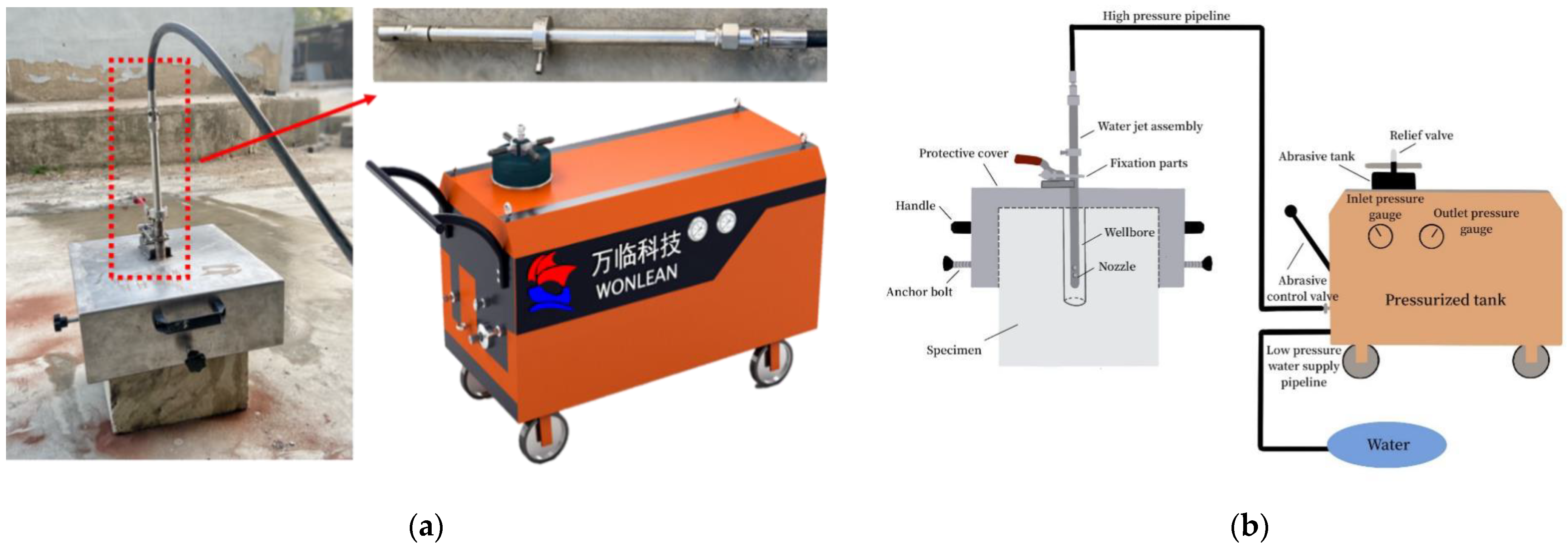
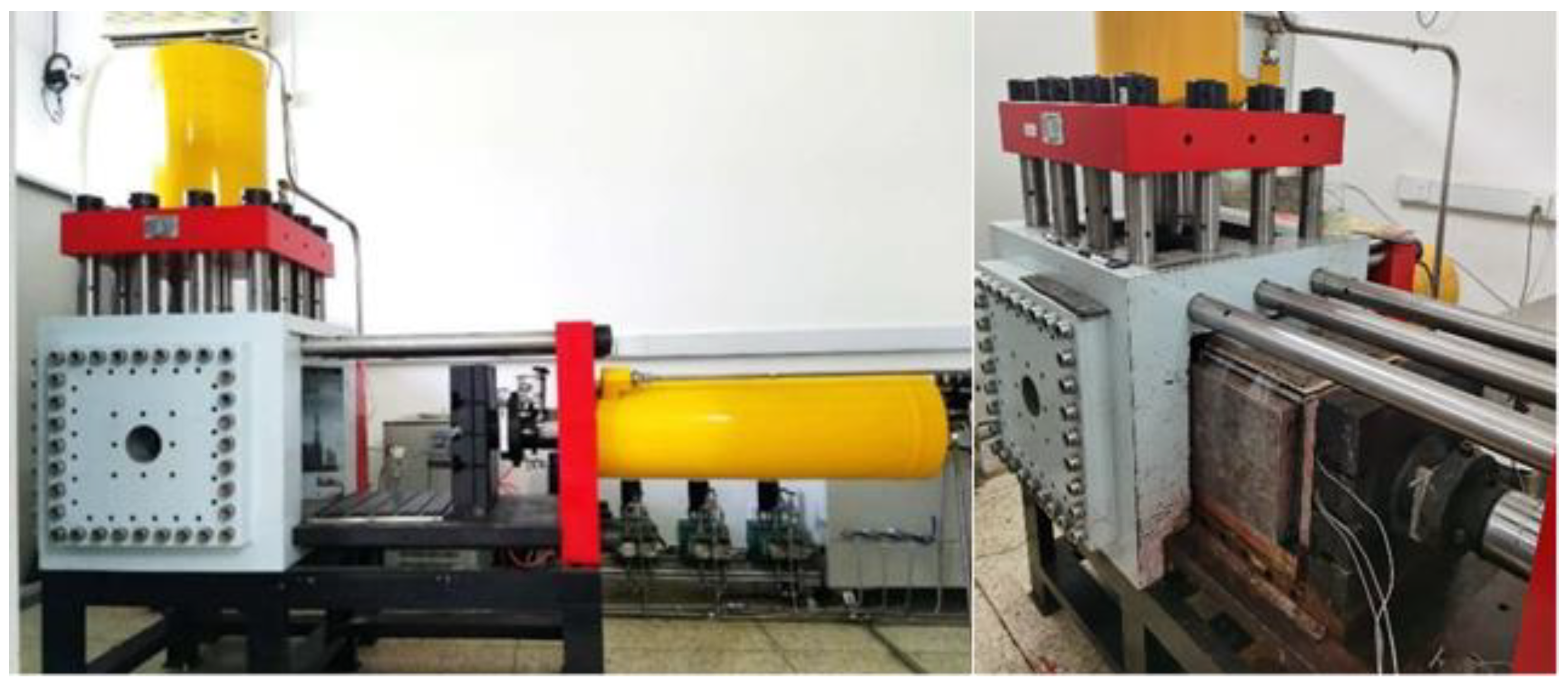
2.1. Perforation Simulation Apparatus

Figure 1 shows the physical drawing and schematic diagram of the hydraulic jetting perforation apparatus. This perforation system comprises a pressurized tank, water jet assembly, nozzle, protective cover, high-pressure pipeline, and low-pressure water supply pipeline. The operating pressure of the apparatus is 25 MPa with a maximum injection rate of high-pressure water of 15 L/min. An inlet and an outlet pressure gauge are installed to monitor the pressure status. Since the internal diameter of the steel casing used in fracturing experiments is generally between 22 mm and 28 mm, and the outer diameter of the hydraulic jetting gun is 23 mm, it applies to all fracturing samples with a inner casing diameter greater than 25 mm. The fracturing sample can be perforated using a 80-mesh garnet sand abrasive mixed in high-pressure water. Variable perforation parameters, including perforation angle, length, and depth can be achieved. A specific perforation angle can be achieved by rotating the hydraulic nozzle and different perforation lengths are obtained by controlling the jetting time.

2.2. Reservoir Information

The Mahu conglomerate reservoir depth ranges from 2500 to 3900 m. The Triassic Baikouquan formation (T1b) and Permian Urho formation (P3w) are the primary development horizons [25,26,27,28]. The distribution of the Baikouquan formation (T1b) is generally stable. The average thickness of the Baikouquan formation is 138 m, and the average thickness of T1b1, T1b2, and T1b3 are 46.0 m, 47.0 m, and 45.0 m, respectively. The rock mineral composition of the T1b2 section of the Baikouquan formation is mainly composed of quartz (35.5%), followed by feldspar (27.5%) and clay (23.2%), and a small amount of calcite (10.3%). The average porosity is 9.78%, and the average permeability is 2.4 × 10⁻³ μm2. This paper conducts research based on the Ma 18 well area data.

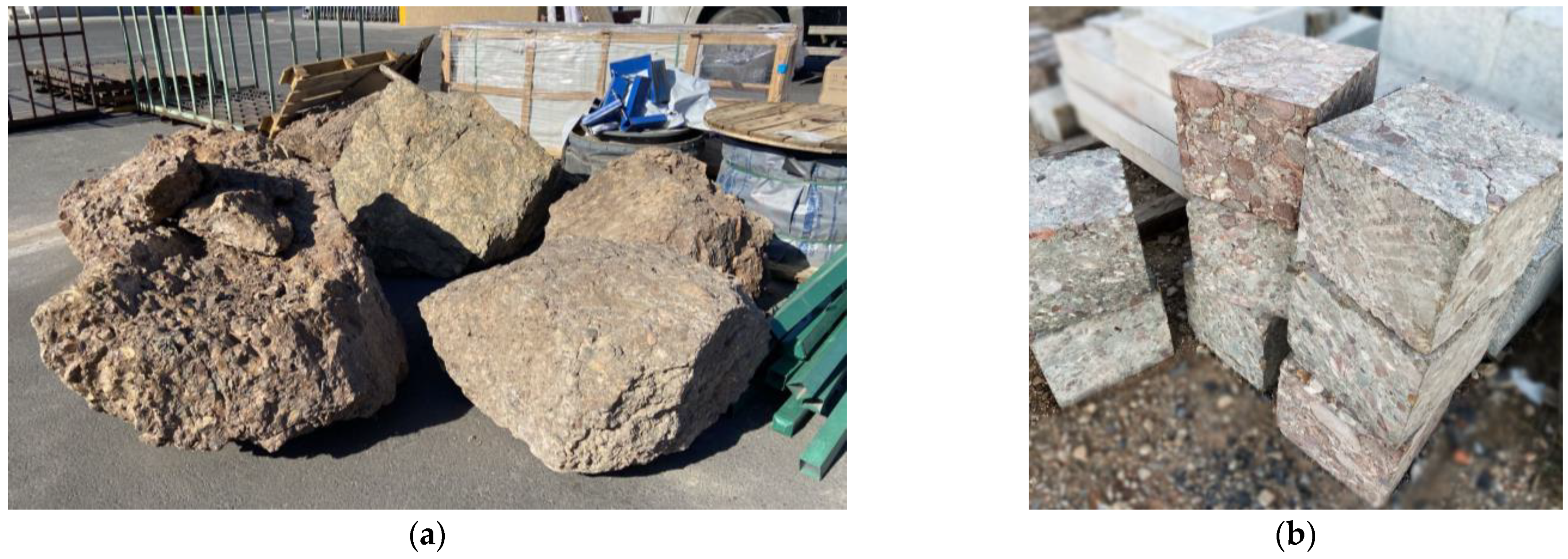
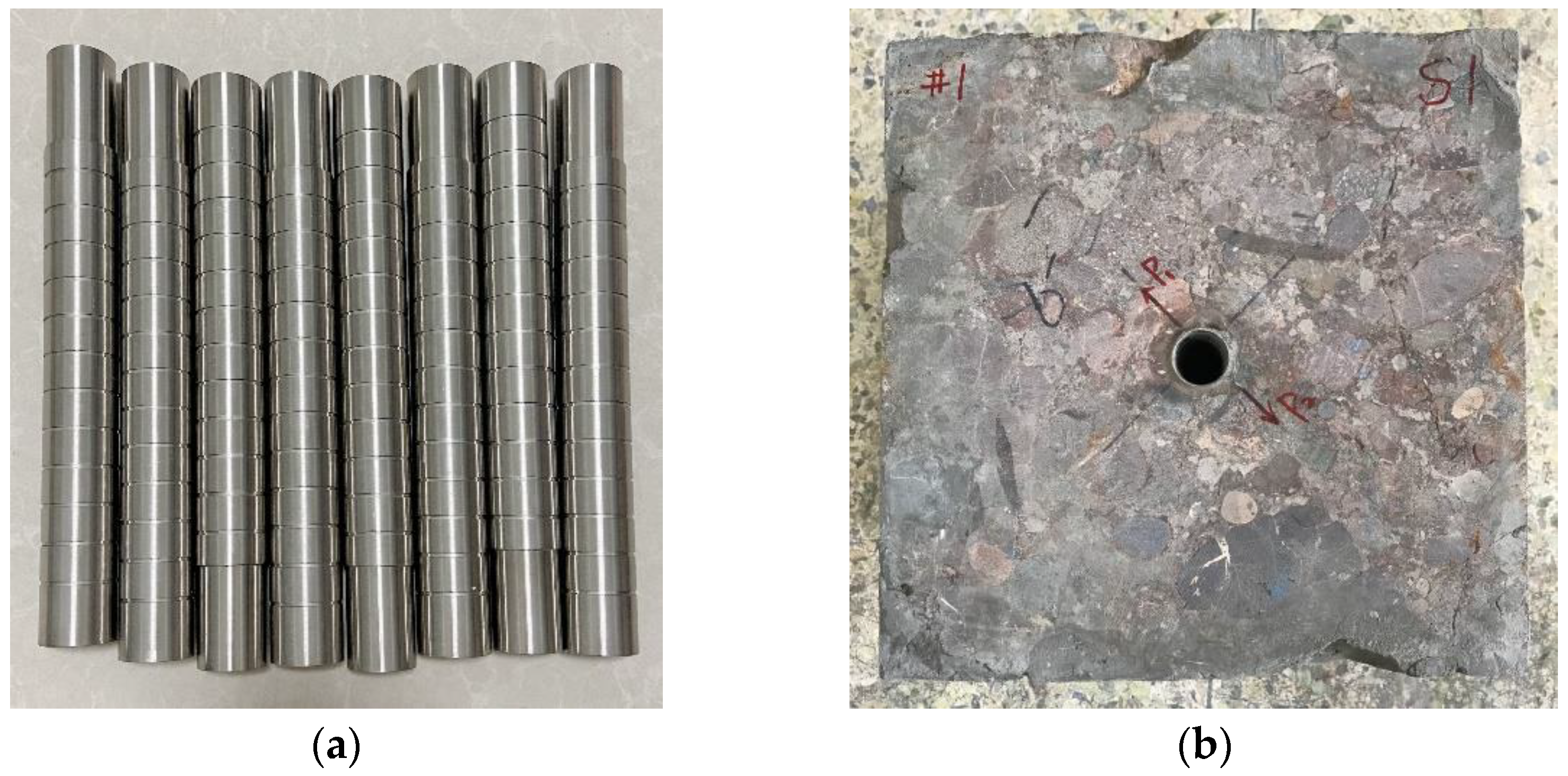
2.3. Specimen Preparation

Five outcrops (Figure 2a) were excavated in Block Ma18. The brief specimen preparation procedures are as follows: Firstly, the outcrops were cut into cubic specimens of 300 mm × 300 mm × 300 mm (Figure 2b). Secondly, a borehole with a 34 mm diameter and a 250 mm depth was drilled in the center of each specimen. Thirdly, a steel pipe (Figure 3a) with an outer diameter of 30 mm, an internal diameter of 25 mm, and a length of 250 mm was placed inside the borehole, and the annulus between the borehole and the steel pipe was bonded by high-strength epoxy resin to simulate the cementing process, as shown in Figure 3b.

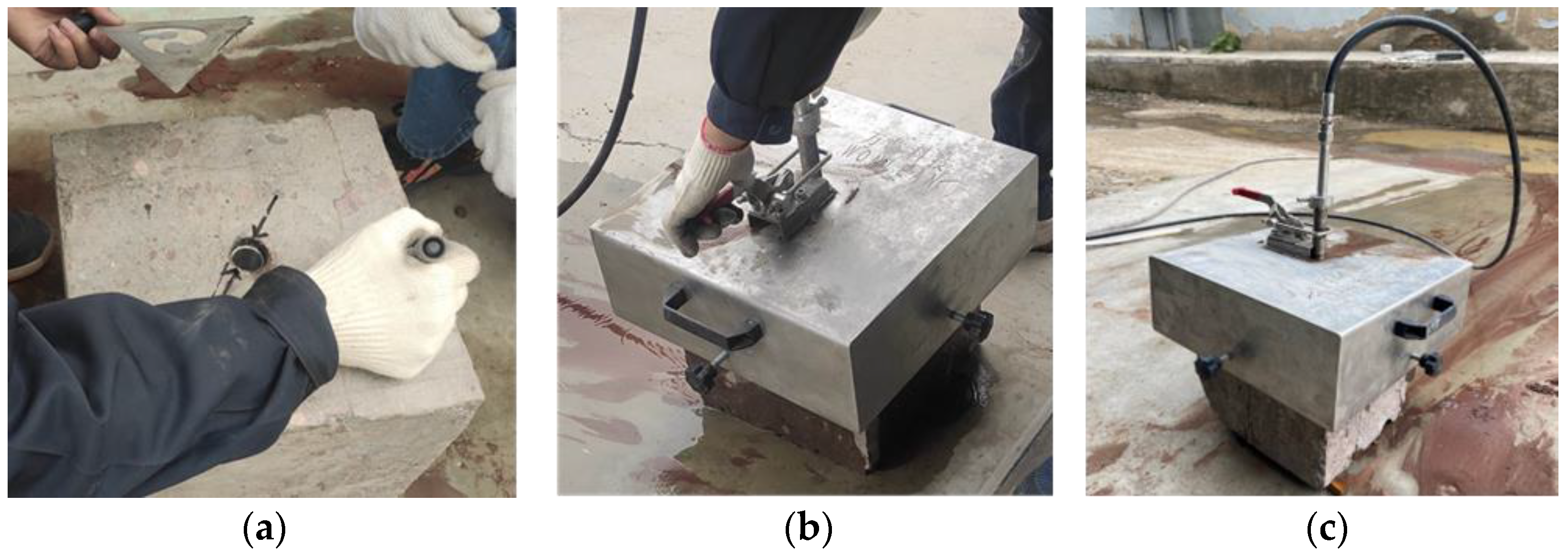
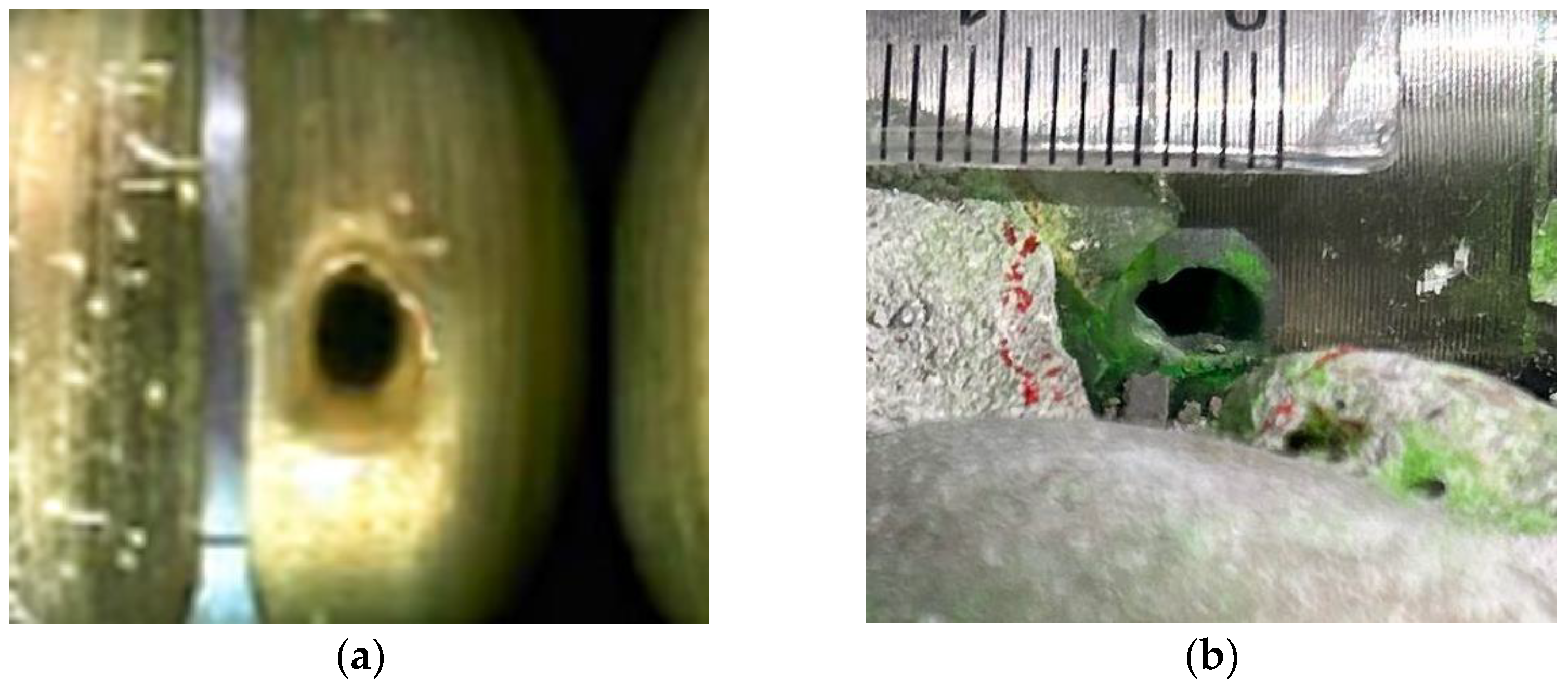
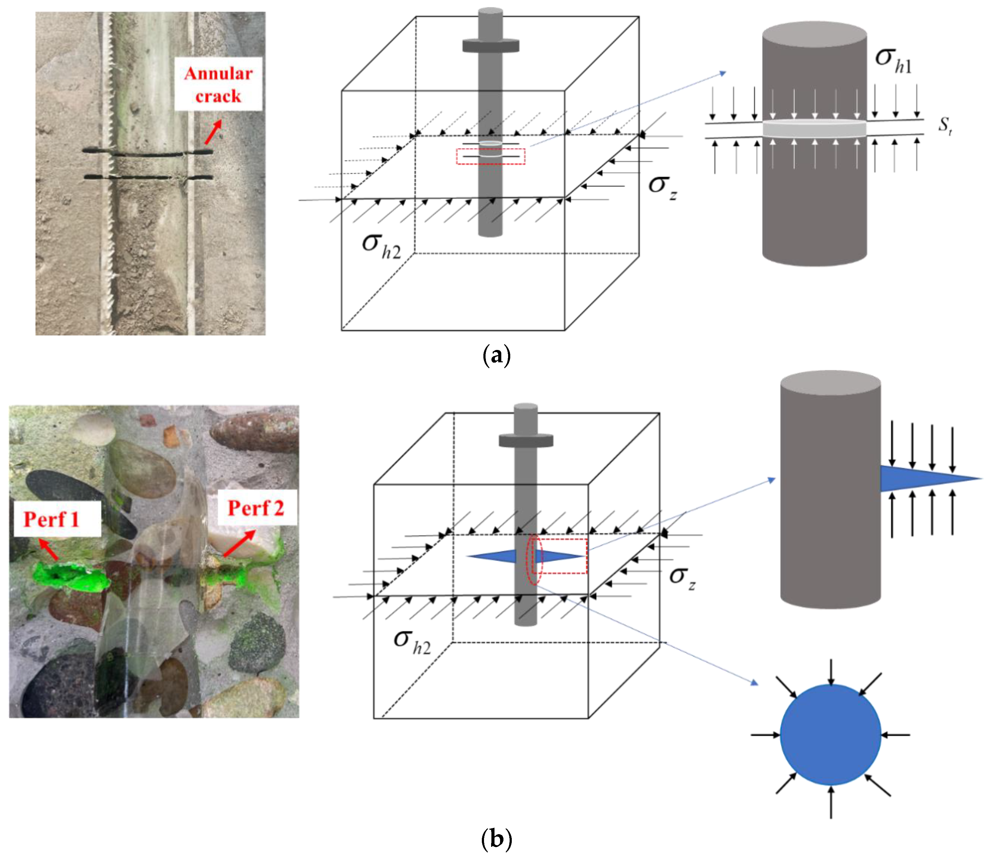
2.4. Perforating Process

After 24 h cementation, the perforating operation is performed; the brief perforation processes are as follows: (1) determine the in situ stress direction and mark the perforation orientation according to the experimental schedule (Figure 4a); (2) locate and orient the nozzle with specified parameters in the borehole using the fixation parts and the protective cover (Figure 4b); (3) perform hydraulic jetting for a specified time (Figure 4c). It is worth noting that the relationship between hydraulic jetting time and perforation length varies for different wellbore materials and rocks, which should be obtained in advance through tests. Table 1 shows the relationship between perforation length and hydraulic jetting time for the specimen in this study.
Figure 5 displays the perforation hole morphology comparison of on-site and laboratory settings. Clearly, the holes made from hydraulic jetting can simulate the perforation in the reservoir well in terms of perforation length and phase angle. The new laboratory perforating method restored the in situ perforation sufficiently. To further illustrate the improvement of the new perforation method, we compared slotting and hydraulic jetting for the perforation simulation in the experiments in terms of the mechanics (taking horizontal well as an example).
Figure 6 illustrates the difference between the two approaches in terms of the force condition. Figure 6a reveals the perforation made by the slotting. σh1 represents the minimum horizontal principal stress, σh2 represents the maximum horizontal principal stress, σz represents the vertical stress, and St represents the tensile strength. The circular fractures formed by slotting are highly affected by vertical stress, and the mechanical failure mode is tensile failure. Figure 6b displays the perforation holes made by the new perforating apparatus. The perforation wall is subjected to circumferential stress (also known as the ‘hoop stress’) along the perforation tunnel [29], and this mode of stress aligns with that of the field, which is closer to the actual perforation state.
In this study, the perforation diameter was 5 to 6 mm. The perforation length was 4 to 5 cm. The perforation phase angle is defined as the acute angle between the axis of the perforation and the horizontal principal stress direction, comprising 0°, 30°, 45°, and 60°. The perforation depth is 12 cm from the wellhead, as shown in Figure 7.

3. Acid Pretreatment for Fracturing

Before fracturing, the specimens were pretreated by different acid types (Figure 8). A 3% corrosion inhibitor was added to the acid solution to protect the steel pipe. The 15 min, 30 min, 60 min, 90 min, and 120 min injection times were tested to study the influence of acidizing time. The other four specimens without acidizing were used as the control groups.

4. Triaxial Hydraulic Fracturing Experiment

4.1. Mineral Composition and Rock Mechanical Properties of Rock Samples

We conducted a series of property experiments on the Mahu conglomerate outcrops. The results of the X-ray diffraction tests indicated that the mineral composition is mainly quartz (35.29%), followed by feldspar (25.12%) and clay (21.22%). The carbonate content is relatively low (9.52%). Mud acid can effectively dissolve feldspar and clay, which is recommended for acid pretreatment in the Mahu area. Additionally, the average permeability is 2.2 × 10⁻³ μm2, the average porosity is 10.85%, the average Young’s modulus is 25.19 GPa, the average Poisson’s ratio is 0.27, and the tensile strength of the rock is 5.54 MPa. The mineral composition and physical property parameters of the outcrops are generally consistent with the geological data of the T1b2 section of the Baikouquan formation, which validates that the outcrop obtained in the field has similar properties to the formation and the experimental results are reliable.

4.2. Triaxial Fracturing Experimental Procedures

4.2.1. Experimental Apparatus

A large true triaxial hydraulic fracturing system can perform the fracturing experiment on a 300 mm cubic rock sample, as shown in Figure 9. The triaxial pressure loading system can achieve three principal stresses on the cube rock samples. Considering the in situ stress (σhmin = 63 MPa σHmax = 75 MPa, and σv = 102 MPa) and the performance of the equipment, σhmin was set as 5 MPa, σHmax, 17 MPa, and σv, 25 MPa in this study. The fracturing fluid viscosity, μ (15 mPa·s), is taken from the field data. The injection rate was set based on the geometrical similarity principle shown in Equation (1) [30,31,32,33,34].
Q F A F × H F = Q M A M × H M ,
where Q is the displacement, m3/min; A is the cross-sectional area of the wellbore, m2; H is the fracture length, m; the subscript M denotes the modeling parameters; the subscript F denotes the field parameters. Equation (1) illustrates that the dimension ratio should be equaled for the laboratory and the field. According to data in the field, the injection rate Q is approximately 12–14 m3/min, and the injection rate in the experiment was set at 130 mL/min. The detailed experimental scheme is in Table 2.

4.2.2. Experimental Procedure

The procedure of the triaxial fracturing experiment is summarized as follows: (1) Load the cube rock sample into the chamber and connect the pipelines. (2) Apply three principal stresses from the x, y, and z axes through a hydraulic pressure system. (3) Start the injection pump at a constant rate and record the injection pressure until the specified time. (4) Open the fracturing specimen to inspect the fracture pattern and analyze the results.

4.3. Experimental Results and Analysis

Twenty sets of experiments were conducted. The results are displayed in Table 2. The average breakdown pressure for the specimens without acidizing (1#~4#) was 14.56 MPa, while the average breakdown pressure of the acidified specimens (5#~20#) was 6.87 MPa, with a decline of 7.7 MPa. The acid pretreatment strongly influenced the breakdown pressure with a positive effect. All the fracturing specimens were opened along with the hydraulic fractures to observe the fracture initiation morphology.

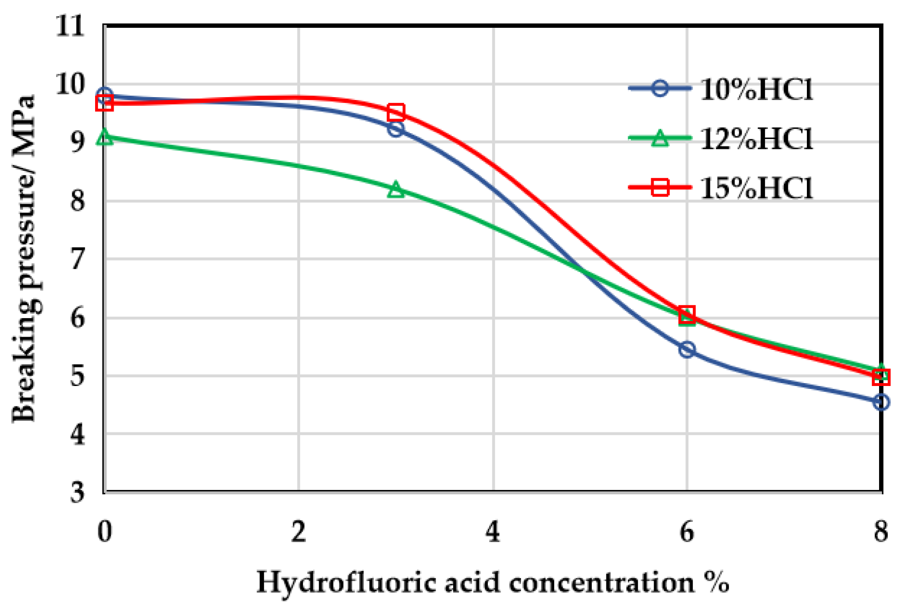
4.3.1. Effect of Acidizing

It is essential to select an optimal ratio of HF to HCl and concentrations for a particular formation, which directly determines the effectiveness of the acid pretreatment. Two kinds of acid solutions, hydrochloric acid and mud acid, were tested in the experiment. Both acids can lower the breakdown pressure. However, the breakdown pressure of the three groups of specimens treated with hydrochloric acid is still relatively high (average 9.52 MPa), and the treatment results are unsatisfactory. Specimens 5# and 9# developed natural fractures near the wellbore, showing lower breakdown pressure values compared to specimen 13# (Figure 10). The breakdown pressures of specimens 5# and 9# should be higher than the current values (9.8 MPa and 9.1 MPa), without natural fractures developing.
Mud acid is more effective in the Mahu depression. The reason for this is that the carbonate content in this area is low, but the feldspar content is relatively high. HCl dissolves the carbonates only, and mud acid dissolves both carbonate and silica-aluminates. Therefore, more minerals were dissolved by the mud acid. Multiple comparative experiments were conducted with different concentrations of acid solution to further optimize the acid system suitable for this area. The acidizing effectiveness remained stable with a weak regularity when the concentration of the hydrochloric acid changed, since the carbonate content is low and natural outcrops have a strong heterogeneity and different physical properties. Nevertheless, hydrochloric acid is essential, and is combined with hydrofluoric acid to form mud acid, which maintains a low pH value. Moreover, hydrochloric acid can promote the dissolution of hydrofluoric acid. Therefore, considering the economic cost of development, a lower concentration of hydrochloric acid is recommended. When the concentration of hydrochloric acid is fixed, the concentration of hydrofluoric acid increases from 0% to 8%, and the breakdown pressure declines rapidly (Figure 11). When the concentration of the hydrofluoric acid varies from 6% to 8%, the breakdown pressure rarely changed.
Xue et al. [35] conducted experiments on the dissolution rates of HCl, HF, and mixed solutions of HCl and HF at different acid concentrations and treatment times. The results showed that the dissolution rate was highest at the HF concentration of 9%. High concentrations of HF could lead to a decline in the dissolution rate, since the reaction between HF and clay and feldspar also involves second-order and third-order reactions. Furthermore, they usually produce precipitation (mainly silica gel precipitation). Due to the variation between the HF concentration of 6% and 8% in this experimental result (Figure 11), a combination of 10%HCl + 6%HF mud acid is preferred.
The acid–rock contact time is a crucial factor in the acid pretreatment design as well. Based on the mineral composition of the Mahu sag and the above experimental results, 6%HF + 10%HCl mud acid was selected to investigate the acid treatment effect. Under the same experimental conditions, the breakdown pressure decreases with the rise in the acidizing time, especially for a shorter contact time (for instance, less than 30 min). Increasing the contact time from 15 min to 30 min diminished the breakdown pressure by 64.6%. Above 60 min, the dissolution rate decreased, and the breakdown pressure almost no longer continued to decline and maintained a steady value. The reason for this is that the amount of soluble minerals is certain. After a particular time, soluble minerals are completely dissolved, leaving insoluble minerals. At this time, even if the acid pretreatment time continues to increase, there will be no more obvious dissolution, resulting in no further decrease in the breakdown pressure. It is worth noting that the breakdown pressure of specimen 19# is slightly higher than that of specimen 18#. There are no natural fractures developed near the wellbore of both samples. However, the gravel distribution of specimen 19# is more complex, and more different sizes of gravel were found near the wellbore. The strong heterogeneity of the conglomerate gives rise to some randomness in the experimental results. Still, after 60 min of acidizing, the overall performance was outstanding, and the breakdown pressure remained almost constant. This relationship curve is illustrated in Figure 12. Compared with the case without acidizing, the breakdown pressure of the specimen with 30 min effective contact time was lowered by about 10 MPa. Furthermore, the breakdown pressure witnessed a stable trend after 60 min. Therefore, an adequate acid–rock contact time of 60 min is recommended.
To further explore the mechanism of the acid pretreatment lowering the breakdown pressure, XRD mineral composition tests were conducted on rock debris scraped near the perforations (within a radial 1 cm range) of fracturing specimens 4#, 5#, 8#, 17#, 18#, 19#, and 20#, respectively. The test results are shown in Table 3. After the hydrochloric acid treatment, the content of carbonate rock decreases. In contrast, the content of feldspar remains stable (specimen 5#), as carbonate can be quickly dissolved by hydrochloric acid, but feldspar cannot. The reaction between HCl and carbonates is
C a C O 3 + 2 H C l C a C l 2 + C O 2 + H 2 O ,
C a M g ( C O 3 ) 2 + 4 H C l C a C l 2 + M g C l 2 + 2 C O 2 + 2 H 2 O
Therefore, the acidizing performance could be better if only hydrochloric acid was applied. In specimens 17#, 8#, 18#, 19#, and 20#, the feldspar and clay react with the HF due to the fluoride ion (F-), showing a great performance. Clay minerals mainly include kaolinite, montmorillonite, illite, and chlorite [36]. The reaction between kaolinite and H+ i:
A l S i 4 O 10 ( O H ) 8 + 24 H F + 4 H + = 4 A l F 2 + + 4 S i F 4 + 18 H 2 O ,
The reaction between montmorillonite and H+ is
A l S i 8 O 20 ( O H ) 4 + 40 H F + 4 H + = 4 A l F 2 + + 8 S i F 4 + 24 H 2 O ,
Feldspar is unstable, with many types, including potassium feldspar, albite, and anorthite. The reaction between potassium feldspar and hydrofluoric acid is
K A l S i 3 O 8 + 22 H F = K F + A l F 3 + 3 H 2 S i F 6 + 8 H 2 O ,
The reaction between albite and hydrofluoric acid is
N a A l S i 3 O 8 + 22 H F = N a F + A l F 3 + 3 H 2 S i F 6 + 8 H 2 O ,
The reaction between anorthite and hydrofluoric acid is
C a A l 2 S i 2 O 8 + 22 H F = C a F 2 + 2 A l F 3 + 2 H 2 S i F 6 + 8 H 2 O ,
The acid treatment time was increased from 15 to 120 min, and the proportion of the carbonate, feldspar, and clay minerals decreased significantly. Wherever the acid solution reached, the soluble minerals would be rapidly dissolved, and there were still areas where the acid was not covered in the experiment, so the proportion of these minerals stayed relatively high. The action distance of the acid is limited. Accordingly, it is crucial to accurately select a targeted acid composition in the acid pretreatment design.
In addition to the in situ stress, the tensile strength affects significantly the breakdown pressure. Therefore, lowering the rock tensile strength is vital to reducing the breakdown pressure. We also cut ten cores with a diameter of 25.4 mm and a thickness of 13 mm using the outcrops, and compared the tensile strength variation before and after acidizing to clarify the mechanism of the acid pretreatment lowering the breakdown pressure. Table 4 provides the tensile strength test results. Group number (a) represents the samples without acidizing, group number (b) represents the samples after acidizing. The average tensile strength of the unacidified and acidized cores are 5.54 MPa and 3.8 Mpa, with a decline ratio of 31.4%. In essence, the acid pretreatment can destroy the strength of the rock and cement to decrease the rock tensile strength, while creating more seepage channels, increasing the porosity and permeability, thereby effectively lowering the breakdown pressure.

4.3.2. Effect of Perforation Angle

To avoid interference with other parameters, we kept the other parameters the same when analyzing the effect of the perforation orientation angle. A perforation orientation angle of 0°, 30°, 45°, and 60° were used to investigate the impacts of the perforation angle on the fracture initiation and breakdown pressure. Figure 13 displays the pressure curves of fracturing specimens 1# to 4#. There is an apparent peak on each pressure curve, which indicates the breaking of the fracturing specimen and gives the breakdown pressure. The breakdown pressure declined by 14.2% when the perforation rotated from 60 degrees to 0 degrees. The overall trend of the breakdown pressure is consistent with the results of numerical simulation studies [37,38,39,40]. The ideal perforation orientation angle is zero, corresponding to the minimum breakdown pressure [41]. Therefore, the larger the perforation angle, i.e., the greater the angle between the perforation axis and the maximum horizontal principal stress, the more energy needs to be consumed to counteract the increasing stress and the more difficult it is to crack. To remove the noise of multiple perforations, the perforation just shoots from one angle, different to the field, in which the perforation shoots from several directions around the wellbore. To decrease the breakdown pressure, ensure that there are perforations with an angle of 0° in the field treatments.
Additionally, the content, distribution, particle size, and hardness of gravel in conglomerate reservoirs can strongly influence fracture initiation. The experimental results showed that the breakdown pressure declined with the decrease in the perforation orientation angle, except in specimens 3# and 4#. The perforation angle varied from 30 degrees to 0 degrees, and the breakdown pressure increased by 0.25 MPa. Figure 14a illustrates the fracture geometry in specimen 4#. The fracture initiates at the perforation base and wall. There is a large piece of gravel closing on the perforation wall, causing an obstruction, and the difficulty of fracture initiation rises. According to the tracer distribution, the fractures are obstructed by gravel and reorient during the initiation process, resulting in a breakdown pressure increase. Comparatively, there is no gravel block around the perforation in specimen 3#. The tracer can be observed around the perforation, indicating that the fractures initiate and propagate at the perforation base in each direction (Figure 14b). Therefore, the breakdown pressure of specimen 4# is supposed to be lower than that of specimen 3# if there were no gravel blocks. Consequently, for heterogeneous conglomerates, when the gravel distribution near the wellbore is similar, the breakdown pressure can be changed by turning the perforation angle without considering the natural fracture. In a conglomerate characterized by strong heterogeneity, when the gravel distribution near the well is quite different, the perforation angle has little effect on the breakdown pressure. Affected by the larger gravel strength, the fracture initiation process may be blocked to generate different paths. In this special case, the gravel distribution is the dominant factor affecting the breakdown pressure.

5. Field Application of Acid Pretreatment

The lithology of the Baikouquan formation is mainly gray conglomerate, gravelly coarse sandstone, sandy conglomerate, and medium coarse conglomerate [42,43]. Based on the geological data, the medium conglomerate is dominant, with a volume fraction of 61.36%, followed by small conglomerate and fine conglomerate, with a volume fraction of 10.07% and 7.29%, respectively. Sandstone is less, with a volume fraction of 8.22% [44]. The minimum horizontal principal stress of the reservoir is 63 MPa, Young’s modulus is 26,038 MPa, Poisson’s ratio is 0.28, and the tensile strength is 5.1 MPa. The acid pretreatment was applied for over 50 horizontal wells in the Ma 18 block.
Figure 15 displays the operation curves of the unacidified and acidized horizontal well. The red line represents the injection pressure, and the green line represents the pump rate. Figure 15a indicates the curve of the horizontal well M1 without the acid pretreatment. The pressure curve has an apparent peak, giving a breakdown pressure of 73.19 MPa. Figure 15b is for well M2 with acid pretreatment. After acidizing, the pressure curve has a tiny peak, significantly decreasing the fracturing difficulty. The breakdown pressure is 65.5 MPa, a proportion of 10.5% lower than the unacidified well M1.

6. Conclusions

This paper developed a new perforation method and conducted a systematic study on how acid pretreatment lowers the breakdown pressure in the Mahu conglomerate reservoirs. By analyzing the experimental results, the following conclusions were reached:
  • The novel perforation method by water jetting in fracturing specimens can better simulate perforation conditions such as the perforation length and angle for the acid pretreatment and triaxial fracturing experiments.
  • The perforation angle has a significant effect on the breakdown pressure. A 0° perforation angle results in the minimum breakdown pressure. It is necessary to ensure there are perforation holes with a 0° perforation angle relative to the maximum horizontal stress for a low breakdown pressure.
  • Acid pretreatment can effectively decrease the breakdown pressure down to 7.7 MPa under experimental conditions. The mechanism of the acid pretreatment to decrease the breakdown pressure is that rock dissolution by the acid reduces the rock tensile strength and increases its permeability. The raised permeability increases the fluid pressure of the reservoir near the wellbore so as to reduce the breakdown pressure of the formation.
  • For the Mahu conglomerate reservoir with a low carbonate content, an acid system of 6%HF + 10%HCl with 60 min plus acid contact time is recommended for the acid pretreatment.
  • The field application of the acid pretreatment to horizontal well fracturing in the Mahu conglomerate reservoirs showed that the acid pretreatment was successful and the breakdown pressure was lowered by 10.5%.

Author Contributions

Conceptualization, W.J. and J.M.; methodology, J.M.; software, X.L.; validation, J.M., G.W. and X.M.; formal analysis, W.J.; investigation, W.J.; resources, X.W.; data curation, X.W.; writing—original draft preparation, W.J.; writing—review and editing, W.J. and J.M.; visualization, G.W.; supervision, X.M.; project administration, J.M.; funding acquisition, J.M. and X.M. All authors have read and agreed to the published version of the manuscript.

Funding

This research received no external funding.

Data Availability Statement

The raw data required to reproduce these findings cannot be shared at this time as the data also form part of an ongoing study.

Conflicts of Interest

Author Guifu Wang was employed by the CNPC Engineering Technology R&D Company Limited. The remaining authors declare that the research was conducted in the absence of any commercial or financial relationships that could be construed as a potential conflict of interest.

References

  1. Zhu, J.; Dong, Y.; Zhu, Y.; Zhang, D.; Hui, J.; Wang, W. Sedimentary reservoir evolution characteristics of lower Triassic Baikouquan formation in Ma18 well area of Mahu sag. J. Hebei Geo Univ. 2022, 45, 32–41. [Google Scholar]
  2. Yun, J.; Qin, G.J.; Xu, F.Y.; Li, X.; Zhong, N.; Wu, W. Development and utilization prospects of unconventional natural gas in China from a low-carbon perspective. Acta Pet. Sin. 2012, 33, 526–532. [Google Scholar]
  3. Tan, P.; Jin, Y.; Han, L.; Shan, Q.; Zhang, Y.; Chen, G.; Zhou, Y. Influencing mechanism of acidification pretreatment on hydraulic fracture for deep fractured shale reservoirs. Chin. J. Geotech. Eng. 2018, 40, 384–390. [Google Scholar]
  4. Wang, Q.; Wen, J.Q.; Yang, Z.C. Application effect analysis of acid fracturing technology in low permeability oilfield development. Oil Gas Prod. 2022, 48, 32–34+51. [Google Scholar]
  5. Zhang, J.F. The Research on Potential Damage and Acid System of Ultra-Low Permeability Sandstone Reservoir in Shanshan Oilfield. Master’s Thesis, Yangtze University, Hubei, China, 2023. [Google Scholar]
  6. Zhang, J.; Li, T.; Wu, J.; Guan, Y.; Xu, M.; Dan, Z.; Zhou, M. Sensitivity evaluation of ultra-low permeability sandstone reservoir and development of acidizing stimulation fluid. Spec. Oil Gas Reserv. 2022, 29, 166–174. [Google Scholar]
  7. Xiong, T. Geological Characteristics of Carbonated Sandstone Reservoir and Acidification Optimization Technology. Master’s Thesis, China University of Petroleum (Beijing), Beijing, China, 2018. [Google Scholar]
  8. Chen, M.; Pang, F.; Jin, Y. Experiments and analysis on hydraulic fracturing by a large-size triaxial simulator. Chin. J. Rock Mech. Eng. 2000, 19, 868–872. [Google Scholar]
  9. Yao, F.; Chen, M.; Wu, X.; Zhang, G. Physical simulation of hydraulic fracture propagation in naturally fractured formations. Oil Drill. Prod. Technol. 2008, 3, 83–86. [Google Scholar]
  10. Hou, B.; Tan, P.; Chen, M.; Yuan, L.; Xiong, Z.; Xu, C. Experimental investigation on propagation geometry of hydraulic fracture in compact limestone reservoirs. Chin. J. Geotech. Eng. 2016, 38, 219–225. [Google Scholar]
  11. Wang, Y.Z.; Hou, B.; Zhang, K.P.; Zhou, C.L.; Liu, F. Laboratory true triaxial acid fracturing experiments for carbonate reservoirs. Pet. Sci. Bull. 2020, 3, 412–419. [Google Scholar]
  12. Shan, Q.L.; Jin, Y.; Han, L.; Zhang, R.X. Influence of spiral perforation parameters on fracture geometry near horizontal wellbores. Pet. Sci. Bull. 2017, 1, 44–52. [Google Scholar]
  13. Feng, F.; Yang, L.S.; Liu, Z.H.; Shen, K. Experimental study on initiation and propagation law of sandstone with axial prefabricated cracks. Saf. Coal Mines 2018, 49, 18–21. [Google Scholar]
  14. Zhang, R.X.; Hou, B.; Shan, Q.L.; Tan, P.; Wu, Y.; Guo, X.F. Parameter optimization of spiral perforations in horizontal well with tight sandstone reservoir. Chin. J. Geotech. Eng. 2018, 40, 2143–2147. [Google Scholar]
  15. Wu, Y.; Hou, B.; Han, H.F.; Zhou, X. Study on the optimization of helical perforation parameters for horizontal wells in the condition of high horizontal stress difference. Chin. J. Undergr. Space Eng. 2019, 15, 226–231. [Google Scholar]
  16. Yu, R.; Zhang, Y.; Zheng, B.; Yang, W.; Tian, Y.; Liu, B. Experimental study on the effects of perforation phasing on fracturing pressure and fracture propagation of thin interbeds. Drill. Fluid Complet. Fluid 2020, 37, 110–115. [Google Scholar]
  17. Hou, Z.K.; Yang, C.H.; Wang, L.; Liu, P.J.; Guo, Y.T.; Wei, Y.L.; Li, Z. Hydraulic fracture propagation of shale horizontal well by large-scale true triaxial physical simulation test. Rock Soil Mech. 2016, 37, 407–414. [Google Scholar]
  18. Liu, N.Z.; Zhang, Z.P.; Zou, Y.S.; Ma, X.F.; Zhang, Y.N. Propagation law of hydraulic fractures during multi-staged horizontal well fracturing in a tight reservoir. Pet. Explor. Dev. 2018, 45, 1059–1068. [Google Scholar] [CrossRef]
  19. Liang, J.; Liu, J.; Xu, Q.Y.; Zhang, L. Study on rock fracture initiation pressure under different hydraulic fracturing parameters. Coal Technol. 2020, 39, 87–89. [Google Scholar]
  20. Zhang, S.C.; Li, S.H.; Zou, Y.S.; Li, J.M.; Ma, X.F.; Zhang, X.H.; Wang, Z.F.; Wu, S. Experimental study on fracture height propagation during multi-stage fracturing of horizontal wells in shale oil reservoirs. J. China Univ. Pet. (Ed. Nat. Sci.) 2021, 45, 77–86. [Google Scholar]
  21. Fu, H.F.; Huang, L.K.; Zhang, F.S.; Xu, Y.; Cai, B.; Liang, T.C.; Wang, X. Effect of perforation technologies on the initiation and propagation of hydraulic fracture. Chin. J. Rock Mech. Eng. 2021, 40, 3163–3173. [Google Scholar]
  22. Wang, Y.H.; Fu, H.F.; Liang, T.C.; Wang, X.; Liu, Y.Z.; Peng, Y.; Yang, L.F.; Tian, Z.H. Large-scale physical simulation experiment research for hydraulic fracturing in shale. In Proceedings of the SPE Middle East Oil and Gas Show and Conference, Manama, Bahrain, 8 March 2015. [Google Scholar]
  23. Bai, J.; Martysevich, V.; Walters, H.; Dusterhoft, R.; Matzar, L.; Sansil, M. Laboratory-scale hydraulic fracturing: Experiment and numerical modeling. In Proceedings of the U.S. Symposium on Rock Mechanics, Houston, TX, USA, 26 June 2016. [Google Scholar]
  24. Fu, H.F.; Zhang, Y.M.; Wang, X.; Yan, Y.Z.; Guan, B.S.; Liu, Y.Z.; Liang, T.C.; Weng, D.W. New stimulation technology research based on impulse fracturing reservoir. Chin. J. Rock Mech. Eng. 2017, 36, 4008–4017. [Google Scholar]
  25. Lei, D.W.; Chen, G.Q.; Liu, H.L.; Liu, X.; Abrimiti, T.K.; Cao, J. Study on the forming conditions and exploration fields of the Mahu giant oil (gas) province, Junggar Basin. Acta Geol. Sin. 2017, 91, 1604–1619. [Google Scholar]
  26. Kang, X.; Hu, W.; Cao, J.; Wu, H. Controls on reservoir quality in fan-deltaic conglomerate: Insight from the Lower Triassic Baikouquan Formation, Junggar Basin, China. Mar. Pet. Geol. 2019, 103, 55–75. [Google Scholar] [CrossRef]
  27. Sang, L.X.; Liu, J.; Wang, G.W.; Wang, S.T.; Li, Q.; Zhang, Y.L. High-quality reservoirs prediction of fan delta in the Triassic Baikouquan Formation in west slope of Mahu sag, Junggar Basin. J. Palaeogeogr. (Chin. Ed.) 2020, 22, 1053–1064. [Google Scholar]
  28. Jiang, Q.P.; Kong, C.X.; Li, W.F.; Qiu, Z.G.; Lu, Z.Y.; Chang, T.Q.; Liu, K.; Chen, D.L.; Li, S.; Yuan, X.G. Sedimentary characteristics and evolution law of a lacustrine large-scale fan delta: A case study from the Triassic Baikouquan formation on the west slope of Mahu sag. Acta Sedimentol. Sin. 2020, 38, 923–932. [Google Scholar]
  29. Waters, G.; Weng, X. The Impact of Geomechanics and Perforations on Hydraulic Fracture Initiation and Complexity in Horizontal Well Completions. In Proceedings of the Spe Technical Conference & Exhibition, Dubai, United Arab Emirates, 26–28 September 2016. [Google Scholar]
  30. Detournay, E. Mechanics of hydraulic fractures. Annu. Rev. Fluid Mech. 2016, 48, 311–339. [Google Scholar] [CrossRef]
  31. Dontsov, E.V. An approximate solution for a plane strain hydraulic fracture that accounts for fracture toughness, fluid viscosity, and leak-off. Int. J. Fract. 2017, 205, 221–237. [Google Scholar] [CrossRef]
  32. Madyarov, A.; Prioul, R.; Zutshi, A.; Seprodi, N.; Groves, D.; Pei, J.; Wong, S.W. Understanding the impact of completion designs on multi-stage fracturing via block test experiments. In Proceedings of the 55th U.S. Rock Mechanics/Geomechanics Symposium, Houston, TX, USA, 20–23 June 2021. [Google Scholar]
  33. Bunger, A.P.; Jeffrey, R.G.; Detournay, E. Application of scaling laws to laboratory-scale hydraulic fractures. In Proceedings of the 40th U.S. Symposium on Rock Mechanics (USRMS), Anchorage Alaska, Alaska, 25–29 June 2005. [Google Scholar]
  34. Zou, Y.S.; Shi, S.Z.; Zhang, S.C.; Li, J.M.; Wang, F.; Wang, J.C.; Zhang, X.H. Hydraulic fracture geometry and proppant distribution in thin interbedded shale oil reservoirs. Pet. Explor. Dev. 2022, 49, 1025–1032. [Google Scholar] [CrossRef]
  35. Xue, L.; Zhu, J.G.; Guo, C.F.; Ni, X.M.; Li, Y.; Cao, Y.X. Experimental optimization of concentration ratio of buffering acid used for removing plugging of coal seam. Saf. Coal Mines 2021, 52, 72–77. [Google Scholar]
  36. Deng, Y.; Xue, R.J.; Guo, J.C. The mechanism of high-pressure high-temperature and low permeability acid pretreatment to reduce fracturing pressure. J. Southwest Pet. Univ. (Sci. Technol. Ed.) 2011, 33, 125–129+199. [Google Scholar]
  37. Wang, S.L.; Dong, K.X.; Dong, H.Y. Effect analysis of perforating parameters upon initiation pressure in low permeability reservoir. Oil Drill. Prod. Technol. 2009, 31, 85–89. [Google Scholar]
  38. Yu, J.Y.; Shen, F.; Gu, Q.H.; Ren, S.S. Influence of perforation parameters on hydraulic fracturing of fracture pressure in horizontal well. Pet. Geol. Recovery Effic. 2011, 18, 105–107. [Google Scholar]
  39. Xue, S.F.; Sun, C.H.; Yu, H.B.; Sun, F. Effect of spiral perforation parameters on formation fracture pressure. Well Test. 2015, 24, 11–13+73. [Google Scholar]
  40. Yang, Y.M.; Li, X.; Wang, Z.; Ju, Y. Influence of perforation parameters on propagation laws of hydraulic fracture in heterogeneous sandstones. China Civ. Eng. J. 2022, 55, 1–9. [Google Scholar]
  41. Andreas, B.; Chavez, F.J.; Sergey, N.; Nihat, G.; Olga, A.; Sergey, C.; Dmitry, K.; Vasily, L. Impact of Perforation Tunnel Orientation and Length in Horizontal Wellbores on Fracture Initiation Pressure in Maximum Tensile Stress Criterion Model for Tight Gas Fields in the Sultanate of Oman. In Proceedings of the SPE Middle East Oil and Gas Show and Conference, Manama, Bahrain, 8–11 March 2015. [Google Scholar]
  42. Liu, X.J.; Xiong, J.; Liang, L.X.; You, X. Rock mechanics characteristics and fracture propagation mechanism of glutenite reservoir in Baikouquan Formation of Mahu Sag. Xinjiang Pet. Geol. 2018, 39, 83–91. [Google Scholar]
  43. Tang, Y.; Xu, Y.; Li, Y.Z.; Wang, L.B. Sedimentation model and exploration significance of large-scaled shallow retrogradation fan delta in Mahu Sag. Xinjiang Pet. Geol. 2018, 39, 16–22. [Google Scholar]
  44. Qin, J.H.; Wang, J.G.; Li, S.Y.; Li, S.; Dou, Z.; Peng, S.M. Characteristics and formation mechanism of hydraulic fractures in tight conglomerate reservoirs of Triassic Baikouquan formation in Mahu Sag. Lithol. Reserv. 2023, 35, 29–36. [Google Scholar]
Figure 1. Hydraulic jetting perforation apparatus. (a) Hydraulic jetting perforation apparatus; (b) schematic diagram of hydraulic jetting perforation apparatus.
Processes 11 03353 g001
Figure 2. Rock samples. (a) Natural outcrops excavated on site; (b) description of what is contained in the second panel. Figures should be placed in the main text near to the first time they are cited.
Processes 11 03353 g002
Figure 3. Wellbore and cementing. (a) Simulated wellbore made of steel; (b) rock samples after cementing.
Processes 11 03353 g003
Figure 4. Perforating procedure. (a) Mark the perforation orientation on the surface; (b) fix the protective cover with specific parameters; (c) work in process.
Processes 11 03353 g004
Figure 5. Perforation hole morphology. (a) The perforation hole took place underground in the field, showing an irregular circular hole; (b) the perforation hole made by the new water jetting apparatus, showing a similar morphology with the hole on site.
Processes 11 03353 g005
Figure 6. Comparison of two kinds of perforations. (a) The perforations by slotting; (b) the perforation by hydraulic jetting.
Processes 11 03353 g006
Figure 7. Schematic of perforation.
Processes 11 03353 g007
Figure 8. Acid pretreatment.
Processes 11 03353 g008
Figure 9. Triaxial hydraulic fracturing apparatus.
Processes 11 03353 g009
Figure 10. Fracture geometry of specimens. (a) Multiple natural fractures (the yellow dotted line) developed near the wellbore observed in specimen 5#; (b) several natural fractures (the yellow dotted line) developed near the wellbore, and one uncracked fracture after experiment was observed in specimen 9#; (c) no natural fractures developed near the wellbore in specimen 13#, several natural fractures observed on the surface away from wellbore only affect the hydraulic fractures propagation, not initiation.
Processes 11 03353 g010
Figure 11. Effect of acid composition on breakdown pressure.
Processes 11 03353 g011
Figure 12. Effect of acid treatment time on breakdown pressure.
Processes 11 03353 g012
Figure 13. Pressure curves of unacidified samples with apparent peak.
Processes 11 03353 g013
Figure 14. A picture of fracture initiation inside the samples. (a) Gravels near the wellbore observed after opening specimen 4#; (b) there are no major gravels observed in specimen 3#.
Processes 11 03353 g014
Figure 15. Pressure curves of horizontal well treatments. (a) Injection pressure curve indicates a peak point with a high breakdown pressure value; (b) there is no obvious crack showing on the injection curve with a low breakdown pressure value.
Processes 11 03353 g015
Table 1. The relationship between jetting time and perforation length for the Mahu conglomerate rock.
NumberPerforation LengthJetting Time
11.8 cm4 min
22 cm7 min
32.5 cm7 min 30 s
43 cm10 min
54 cm18 min 14 s
65 cm20 min
Table 2. Breakdown pressure results under different experimental conditions.
NumberPerforation AngleAcid SystemAcidizing Time (min)Breakdown Pressure
(MPa)
160°--15.65
245°--15.4
330°--13.42
4--13.77
510%HCl309.8
63%HF + 10%HCl309.23
76%HF + 10%HCl305.45
88%HF + 10%HCl304.55
912%HCl309.1
103%HF + 12%HCl308.2
116%HF + 12%HCl306
128%HF + 12%HCl305.08
1315%HCl309.67
143%HF + 15%HCl309.51
156%HF + 15%HCl306.05
168%HF + 15%HCl304.97
176%HF + 10%HCl1512.85
186%HF + 10%HCl603.16
196%HF + 10%HCl903.3
206%HF + 10%HCl1203
Table 3. Mineral composition tests results for different acidizing times.
NumberAcid SystemAcidizing Time (min)Quartz (%)Clay (%)Feldspar (%)Calcite (%)Other (%)
4--35.2921.2225.129.528.85
510%HCl3034.5518.9126.898.0511.6
176%HF + 10%HCl1532.518.1325.759.1814.44
86%HF + 10%HCl3037.516.3322.098.1717.91
186%HF + 10%HCl6037.815.1921.867.8517.3
196%HF + 10%HCl9038.4814.6721.367.6717.82
206%HF + 10%HCl12038.2614.5521.157.5518.49
Table 4. Experimental parameters and results.
NumberTensile Strength (Before)
(MPa)
NumberAcid SystemContact Time
(min)
Tensile Strength
(After)
(MPa)
(1)a4.72(1)b6%HF + 10%HCl104.53
(2)a4.33(2)b6%HF + 10%HCl203.59
(3)a6.83(3)b6%HF + 10%HCl304.64
(4)a5.39(4)b6%HF + 10%HCl603.13
(5)a6.42(5)b6%HF + 10%HCl1203.08
Disclaimer/Publisher’s Note: The statements, opinions and data contained in all publications are solely those of the individual author(s) and contributor(s) and not of MDPI and/or the editor(s). MDPI and/or the editor(s) disclaim responsibility for any injury to people or property resulting from any ideas, methods, instructions or products referred to in the content.

