Article

3D Printed, Single-Use Bioreactor with Integrated Inline Sensors for Microbial and Mammalian Cell Cultivation—A Case Study

1
Institute of Chemistry and Biotechnology, School of Life Sciences and Facility Management, ZHAW Zurich University of Applied Sciences, 8820 Waedenswil, Switzerland
2
Neue Materialien Bayreuth GmbH (NMB), 95448 Bayreuth, Germany
3
PreSens Precision Sensing GmbH, 93053 Regensburg, Germany
*
Author to whom correspondence should be addressed.
Processes 2023, 11(11), 3231; https://doi.org/10.3390/pr11113231
Submission received: 25 October 2023 / Revised: 10 November 2023 / Accepted: 11 November 2023 / Published: 16 November 2023
(This article belongs to the Section Pharmaceutical Processes)

Abstract

:
The development of upstream bioprocesses necessitates small, instrumented bioreactors for investigating and optimizing production processes in a cost-effective manner. Due to advances in both the equipment and the materials used in additive manufacturing, 3D printing of customized bioreactors is now in the realm of possibilities. In this study, a small-scale 3D printed bioreactor suitable for mammalian and microbial cultivations was developed, featuring a working volume of 90 mL, inline pH and dissolved oxygen probes and a levitating magnetic stirrer. Aeration channels and a sampling port were printed directly into the vessel walls. Additionally, the vessel was equipped with a 3D printed customizable optical biomass-sensor. The bioreactor’s performance was evaluated through technical characterization and proof of concept cultivations, demonstrating that mixing time and oxygen mass transfer were sufficient for cultivating mammalian as well as microbial cells at high cell densities. Specifically, an Escherichia coli fed-batch cultivation achieved a maximum OD600 of 204. Furthermore, a fed-batch cultivation of an IgG antibody-producing Chinese hamster ovary cell line reached a peak viable cell density of 10.2 × 10⁶ cells mL−1 and a maximum product titer of 2.75 g L−1. Using a three-parameter fit, the inline biomass signal could be correlated to the corresponding offline values with satisfactory accuracy, making it possible to monitor cell growth in real-time.

1. Introduction

The ever-increasing demand for biopharmaceutical products necessitates the improvement of current production processes and the streamlining of research and development for new products, such as monoclonal antibodies and vaccines. A strategy often employed to address this is the use of scale-down models, since research and development at production scale is very expensive [1]. These scale-down models normally consist of a fully instrumented, sub-liter scale bioreactor, with geometric similarity to the production bioreactor. Widely used multi-parallel reactor systems used for scale-down models include the Ambr 250 and Ambr 15 from Sartorius AG [2,3]. To successfully emulate large scale cultivations, the scaled down bioreactor must have the same process control capability as the production bioreactor, ensuring accurate measurement and control of critical process parameters like temperature, pH and dissolved oxygen (DO). Incorporating additional probes, such as inline biomass or substrate sensors is also advantageous, as it can provide deeper process insight. Furthermore, these systems should facilitate user-friendly sampling, feed addition and medium exchange. In general, a high degree of automatization is desired to enable the simultaneous operation of several bioreactors, thereby supporting high throughput-screening. Modern high throughput bioreactor systems are predominantly made from plastics and discarded after one use [4,5]. The adoption of single-use technology, which, in the context of the bioreactor encompasses the entire vessel and its internals, has numerous advantages, such as higher flexibility and reduced risk of contamination. However, it also has its limitations, such as the presence of leachables, which are extensively discussed in the literature [6,7].
Traditionally, the geometry of the bioreactor vessel has not been considered an easily changeable parameter. While custom building classical reusable bioreactors is possible, manufacturing a multitude of differing vessel geometries is time consuming and can be financially prohibitive. The same constraints extend to single-use bioreactors, since specialized molds and tools need to be created, rendering iterative design evaluation both slow and expensive. A potential solution to this challenge is additive manufacturing (AM), which has already been employed in rapid prototyping approaches to expedite product development [8]. However, only employing AM in the development phase does not leverage its full potential. Recent developments in AM technology have enabled not only the design, but also the production of customized bioreactors in small batches, which unlocks the possibility of creating tailor-made vessel geometries [9]. Depending on specific requirements, the bioreactor can be equipped with customized ports for the insertion of various probes, addition lines or the attachment of a perfusion device.
At small scales, bioreactors have historically been manufactured from optically clear materials like glass or plastics [10]. While visual access into the bioreactor is not strictly necessary for experimenters, it is advantageous for detecting foaming, as well as volume and color changes. High transparency is also crucial for optical sensors, as it enables non-invasive sensing through the vessel wall.
Modern optical pH and DO single-use sensors operate based on the principle of fluorescent dyes, which can reversibly change their fluorescence in response to the detected parameters [11]. This is accomplished with a layer of pH or oxygen sensitive material within the bioreactor, which is in contact with the culture broth. The fluorescent properties are read through an optical window, typically constructed from optically clear thermoplastic polymers or glass. A polymer optical fiber facilitates the connection between the optoelectronics and the sensor material, transmitting the excitation light pulses as well as the resulting fluorescent emission.
Biomass measurement in microbial cultures is typically conducted by measuring the optical density of the broth at 600 nm [12], using spectroscopy with a fixed pathway of 10 mm. The correlation between biomass and light attenuation, mediated by scattering and absorption, is only linear at a restricted lower range [13,14]. For this reason, samples with high biomass content typically need to be diluted prior to measurement. However, this approach is incompatible with inline sensing. Instead, the length of the optical pathway is adjusted to the required optical density range, which is determined by the specific organism being cultivated. To increase the linear measurement range, multiple sensors, each with optical pathways of varying lengths, can be integrated into a bioreactor.
For optical inline sensing technology to function effectively, an unobstructed view into the bioreactor’s interior needs to be provided. This can be achieved through optical windows or, in the case of 3D printed bioreactors, by the material itself. However, this application poses high demands on the material and AM technology as the vessel requires high transparency, that is, high light transmission and low surface roughness, and the used material must be biocompatible.
Since AM operates on a layer-by-layer manufacturing strategy, porosity is often a major problem associated with this technique, resulting in a loss of both transparency and impermeability. The same layer-by-layer concept can also result in a rough surface, and it is often possible to see the individual layers with the naked eye. Therefore, careful evaluation of the process parameters is required to ensure satisfactory performance at high accuracy and process stability.
Arburg Plastics Freeforming (APF) technology provides a viable solution for manufacturing parts within these stringent constraints [15]. APF belongs to the extrusion-based processes, but instead of plastic filaments, individual droplets are deposited. A notable advantage of this is that inexpensive standard injection molding granules can be used as a raw material. This means that a large selection of different thermoplastic granules can be used for a variety of applications [16].
The fundamental operation of APF is similar to injection molding. The plastic granulate is introduced to the screw, where the material is melted. However, in contrast to injection molding, APF employs an axially non-moving screw. Furthermore, instead of a mold, a piezo actuator-controlled nozzle is installed at the screw’s end. This configuration allows control over not only the printing speed, nozzle temperature and environmental temperatures, but also the discharge rate, which considerably influences material compaction and, consequently, the porosity of the parts.
In this study, the additive manufacturing of radiation-sterilizable, single-use bioreactors, suitable for both mammalian and microbial cultivations, was explored. A similar approach was recently undertaken by Rehfeld et al., albeit at lower volumes and with only minimal process control capabilities [17]. Conversely, the small-scale stirred tank bioreactor developed in this study was fully instrumented, had a working volume of 90 mL, and featured integrated single use biomass, pH and DO sensors. The designed vessel incorporated four baffles, into which gassing channels with openings at the bottom were printed, providing an integrated sparging solution. For agitation, a levitating impeller was installed in the bottom of the bioreactor. This bottom-driven magnetic stirring approach enables agitation at low filling levels and decreases the contamination risk, since no penetrating stirrer shaft is required [18]. Additionally, no space is occupied on the headplate of the bioreactor, thereby affording ample room for the implementation of probe ports and addition lines. This is especially advantageous for small-scale bioreactors, since the agitator in top driven designs often occupies the majority of the headplate, complicating the placement of all the required ports.
The manufactured bioreactor prototypes underwent rigorous testing through the execution of standardized fed-batch cultivations with Escherichia coli and Chinese hamster ovary (CHO) cells. While E. coli processes pose high demands on oxygen transfer rates [19], CHO cultivations are more susceptible to potential issues arising from leachables [20]. Each organism presented its unique set of challenges and demands on the bioreactor system, serving to comprehensively evaluate its capabilities and limitations. During the development of the bioreactor, multiple cultivations were carried out with both organisms. However, only the most recent cultivation with the optimized bioreactor geometry was reported in this publication.

2. Materials and Methods

2.1. Additive Manufacturing and Characterization of Printed Material

The commercially available injection extrusion-based printer ARBURG Plastic freeformer (Arburg, Loßburg, Germany) was used to manufacture sample prints and the bioreactor vessel. The slicer software provided by Arburg was used to prepare the specimens for printing. NAS 30 styrene methyl methacrylate (SMMA), from the manufacturer INEOS Styrolution (Frankfurt a. Main, Germany), was selected as a transparent and biocompatible thermoplastic material. Before printing, the SMMA granules underwent an 8 h drying process at 80 °C using the drying unit integrated with the APF printer. The drying system remained active throughout the entire printing process.
Given that no profile was available for the chosen material in the Arburg database, a series of optimization steps were required to achieve the desired properties in the final vessel design. First, a temperature profile was created. Due to the similarities between APF and injection molding, the cylinder temperature was chosen based on the manufacturer specifications and was set to 235 °C [21]. Throughout the entire process, the layer height was consistently maintained at 0.2 mm. The subsequent step involved qualifying the material to set other important parameters in the slicer, such as printing speed or filling density, by determining the shape factor, which is the width-to-height ratio of a single chain drop.
Based on this information, samples with 30 × 30 × 3 mm3 dimensions were manufactured with varying printing parameters to investigate different discharge rates (76%; 80% and 84%), build temperature (70 °C; 80 °C and 90 °C) and printing speed (20 mm s−1; 40 mm s−1 and 60 mm s−1). The optimized parameters used to print the bioreactor were a printing speed of 40 mm s−1, a discharge rate of 80% and a building chamber temperature of 80 °C.
The printed samples were characterized based on surface roughness, light transmission and biocompatibility. The surface roughness was measured with the perthometer ‘Waveline W20’ from Jenoptik AG (Jena, Germany), considering the roughness value Ra as the reference value. To assess the roughness, a thin needle was set to move over the sample’s surface at 0.5 mm s−1. It had a sensing distance of 15 mm, and the cut-off wavelength λc was set to 2.5 mm. Light transmission measurements were performed on the “BYK haze-gard plus” using standard light CIE-C (color temperature ~6800 K). The measurement mode was set to transmission and haze. Each specimen was measured three times.
In addition to the technical characterization of the material, a test to identify substances that might migrate from the plastic vessel into the culture broth—potentially inhibiting or even being toxic to the cells (e.g., leachables)—was performed according to the corresponding DECHEMA recommendation [22]. For this purpose, two different test series were carried out with printed SMMA cylinders, each in triplicate. For the first test series, SMMA cylinders were submerged in cell culture medium for 72 h. For the second one, SMMA cylinders were submerged in water for injection (WFI), which was subsequently used for medium production. In both tests, the surface-area-to-volume ratio was 1 cm2 mL−1.
Following the 72 h incubation period, batch cultivations were performed, both with the exposed medium and, separately, the medium produced with exposed WFI, in a 500 mL disposable shake flask with CHO XM 111-10 cells (Culture Collection of Switzerland, Wädenswil (CCOS 837)). The cells were cultivated for five days and samples were taken daily (Inoculation cell density = 0.3 × 10⁶ cells mL−1, working volume = 100 mL, temperature = 37 °C, CO2 concentration = 7.5%, relative humidity = 70%, shaking speed = 120 rpm and shaking diameter = 25 mm). Nonexposed medium and WFI were used as references. In addition to the maximum cell density, viability, substrates and metabolites were analyzed. A detailed description of the test can be found in the DECHEMA recommendation [22].

2.2. Biochemical Engineering Investigations

2.2.1. Computational Fluid Dynamics

In order to characterize the bioreactor in terms of process engineering parameters, computational fluid dynamics (CFD) was used to determine the specific power input. Furthermore, CFD was used to investigate the flushing of the biomass sensor pocket. Simulations were conducted using the open-source toolbox OpenFoam V9. Since the bioreactor can be operated at high stirrer speeds (3000 rpm and 4.3 m s−1) compared to conventional bioreactors, the simulations were carried out using a two-phase approach to account for vortex formation. Hirt’s volume of fluid approach was used (Equations (1)–(3)), wherein a mixed fluid with the physical properties χ is assumed (Equations (4) and (5)) [23]. The stirrer’s rotation was realized by means of the multiple reference frame approach. The investigations were carried out up to a modified Reynolds number of 35,260, where the turbulence was taken into account by means of the k-omega-SST model [24].
The calculations were performed using a high-performance computing setup. Determining the specific power input and the torque at the stirrer was achieved through steady-state simulation, while the flushing study was conducted via transient calculations with a maximum Courant–Friedrichs–Lewy number of 0.9. Post processing was conducted using Paraview 5.10.0 and Python 3.10.
In order to estimate the discretization error and perform economic simulations, a mesh study was performed using the grid convergence index method [25]. For the simulations described here, a mesh with 2.78 million cells was used.
  v = 0
ρ v   t + ( ρ   v   v ) = p + ρ g + v ( v + ( v ) T ) + F    
F = σ κ α
χ = χ i α i ,             χ     [ ρ ,   ν ]
α i = 1 ,             α i { α i |   0   α i 1 }

2.2.2. Experimental Biochemical Engineering Investigations

The main process engineering parameters of the bioreactor were determined with the methods published by DECHEMA [26]. In short, the mixing time (θ) was determined using the decolorization method, the volumetric mass transfer coefficient (kLa) via the gassing-out method and the specific power input (P/V) through torque measurement.
The mixing time measurements were executed at the stirrer speeds used for the CHO and E. coli cultivations (180 and 2000 rpm, respectively). Ten measurements were performed at each stirrer speed. The runs were recorded at 60 frames per second, enabling subsequent frame-by-frame visual evaluation. The kLa was determined under cultivation conditions, with stirrer speeds set to 180 rpm and 2000 rpm and baffle sparging to 20 mL min−1 and 180 mL min−1, respectively. Each measurement was repeated five times and recorded with a Fibox 4 (PreSens GmbH, Regensburg, Germany). The specific power input was determined according to Schirmer et al. [27]. The torque was determined by measuring the electric current and using the motor constant K t . The measurements served to validate the specific power input determined with CFD. Torques were measured for stirrer speeds between 1000 and 2500 rpm.
P / V = 2 π n ( M M 0 ) V
M = K t I               with     K t = 1.13   N   cm   A 1  

2.3. Cultivations

2.3.1. Controller Setup

For all cultivations, a my-Control bioprocess controller (Getinge, Gothenburg, Sweden) was used. Temperature regulation (heating and cooling) was implemented with a machined aluminum heat transfer block which was fitted to the side of the bioreactor and affixes to a Peltier element (Figure 1). For agitation, the bioreactor was placed on a stand-alone PMS-i30 mixer drive (Levitronix, Zürich, Switzerland).

2.3.2. E. coli Fed-Batch

The E. coli fed-batch cultivations were based on the DECHEMA recommendation for biological bioreactor evaluation [28], and they employed the modified fed-batch strategy described by Schirmer et al. [27], based on the medium formulation by Biener et al. [29]. The cultivations were carried out using the E. coli strain W3110 thyA36 supO λ-(ATCC: 27325). Seed cultures 1 and 2 were prepared following the methodology described by Schirmer et al. [28] and were used to inoculate the bioreactor with an OD600 of 1, starting with a volume of 67.5 mL. Due to sampling, the bioreactor volume was reduced to ≈55 mL at the start of feeding. The temperature was maintained at 37 °C using a Peltier element. Throughout the cultivation, the pH was held at ≥6.8 by adding a 20% ammonium hydroxide solution. During the initial batch phase, the bioreactor was aerated with 180 mL min−1 process air (2 vvm of the maximum working volume) over an open pipe sparger. The exponential feed was initiated once a DO spike was detected, which indicated that the glucose was depleted. During the feed phase, the DO was held at 40% by mixing pure oxygen with the sparging gas while keeping the flowrate constant. Upon reaching an OD600 of 150, a bolus feed with 400 g L−1 (NH4)2HPO4 was administered to achieve a concentration of 4 g L−1. Equation (8) was used to calculate the exponential feed, which was implemented using a Maxxis 5 weight controller (Sartorius, Göttingen, Germany). The corresponding variable values are enumerated in Table 1.
F ( t ) = µ s e t     ρ F e e d c s   Y X / S   OD 600 ( t 0 ) C CDW / OD 600 V ( t 0 )   e ( µ s e t ( t t 0 ) )
Every hour, a 1.5 mL sample was drawn from the bioreactor and the following parameters were measured in single determination: offline pH, OD600 using a BioPhotometer D30 (Eppendorf, Hamburg, Germany) and cell dry weight (CDW). Additionally, acetate and glucose concentrations were measured with HPLC.

2.3.3. CHO Fed-Batch

The CHO fed-batch cultivations utilized the ExpiCHO-S 6H8 cell line from Gibco (Thermo Fisher, Waltham, MA, USA), which constitutively express immunoglobulin G (IgG). Unless otherwise stated, the medium and supplements were also sourced from Gibco. The cells were cultivated in Efficient-Pro medium, supplemented with 6 mmol L−1 L-glutamine and 0.1% AntiClumping-Agent, with Efficient-Pro Feed 2 used for feeding.
Inoculum production commenced 7 days before inoculation by thawing a cryovial, and the cells were subcultivated every 2 to 3 days and seeded at a viable cell density (VCD) of 0.3–0.5 × 10⁶ cells mL−1. For this, unbaffled Corning 125 mL shake flasks, with a working volume of 40 mL, were used and incubated at 37 °C, 8% CO2 and 80% relative humidity. The shaker was set to 120 rpm and a shaking diameter of 25 mm. To maintain IgG expression, 400 nmol L−1 methotrexate (Sigma-Aldrich, St. Louis, MO, USA) was added to the N-2 passage.
The bioreactor was inoculated at 85 mL with a VCD of 0.3 × 10⁶ cells mL−1. To prevent contamination, the main cultivation was fortified with 50 μg mL−1 gentamycin (Sigma-Aldrich, St. Louis, MO, USA). Following a 72 h initial batch phase, daily bolus feeding with Efficient-Pro Feed 2 commenced, with the feed volume equating to 2% of the current bioreactor volume, added after sampling. Feeding continued until day 13, resulting in 11 feed additions, with the bioreactor harvested on day 14. Complementary to the feed medium addition, 200 g L−1 glucose solution was added as a bolus feed, based on the cell metabolism, to consistently maintain a glucose concentration in the bioreactor above 2 g L−1. To prevent foaming, 1:10 diluted antifoam C emulsion (Sigma-Aldrich, St. Louis, MO, USA) was added periodically. Throughout cultivation, the temperature was regulated to 37 °C, pH was held at ≤7.2 via CO2 sparging and DO was held at ≥40% via O2 sparging through open pipe spargers integrated into the four baffles. A constant head space aeration of 0.1 vvm (8.5 mL min−1) was applied.
Daily analytics consisted of VCD and total cell density (TCD) measurement, using a Cedex HiRes Analyzer (Roche Diagnostics, Basel, Switzerland). Furthermore, concentrations of glucose, lactate, glutamine, ammonium and IgG were measured using a Cedex Bio Analyzer (Roche Diagnostics, Basel, Switzerland). Only a single sample was drawn per day and all measurements were carried out as single determinations. Offline pH was also measured and used to recalibrate the inline pH sensor if the deviation was higher than 0.05 pH units.

3. Results and Discussion

3.1. Printing Parameter and Material Evaluation

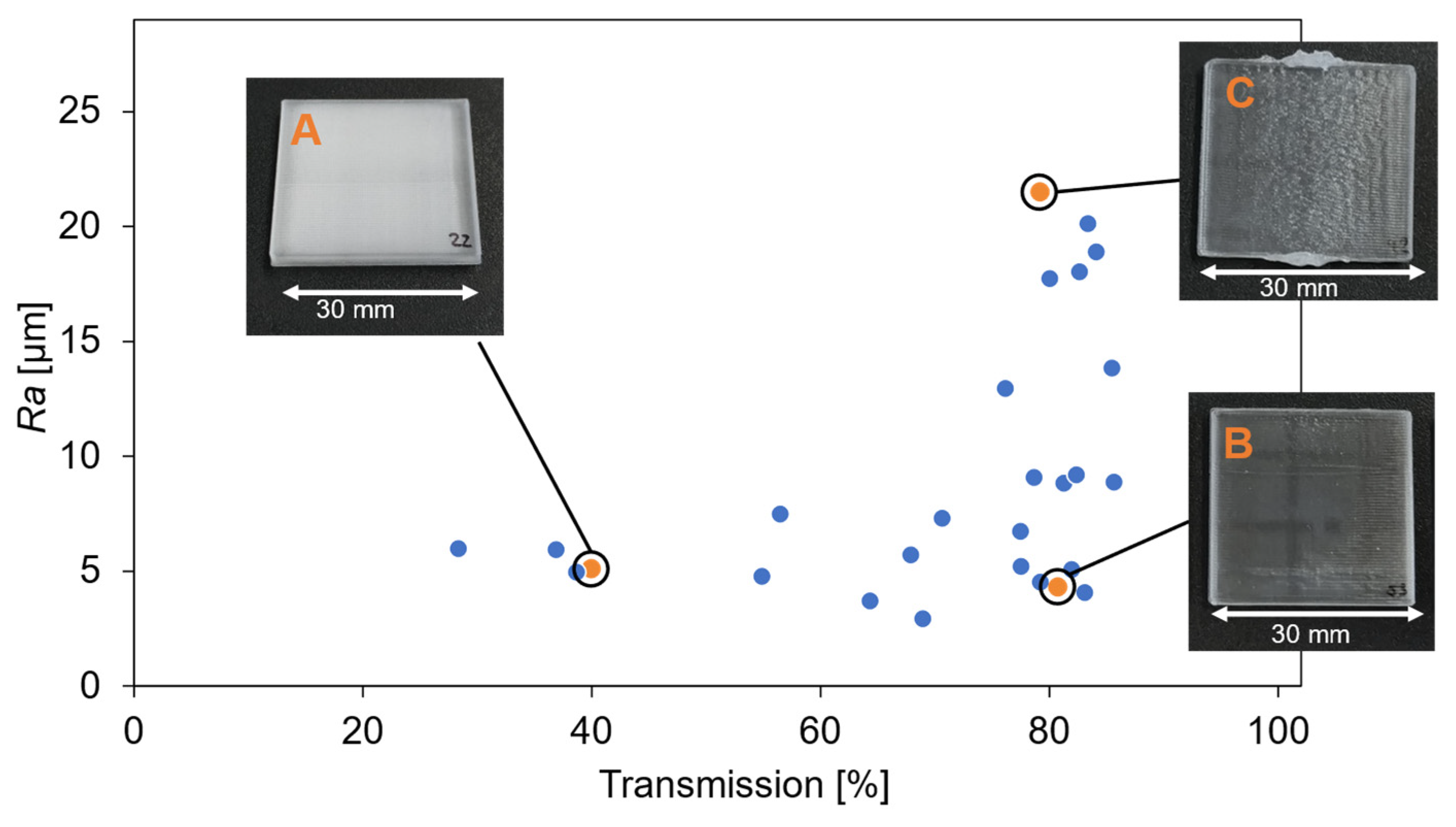
The results from the surface roughness and light transmission measurements of samples manufactured with different printer settings are depicted in Figure 2.
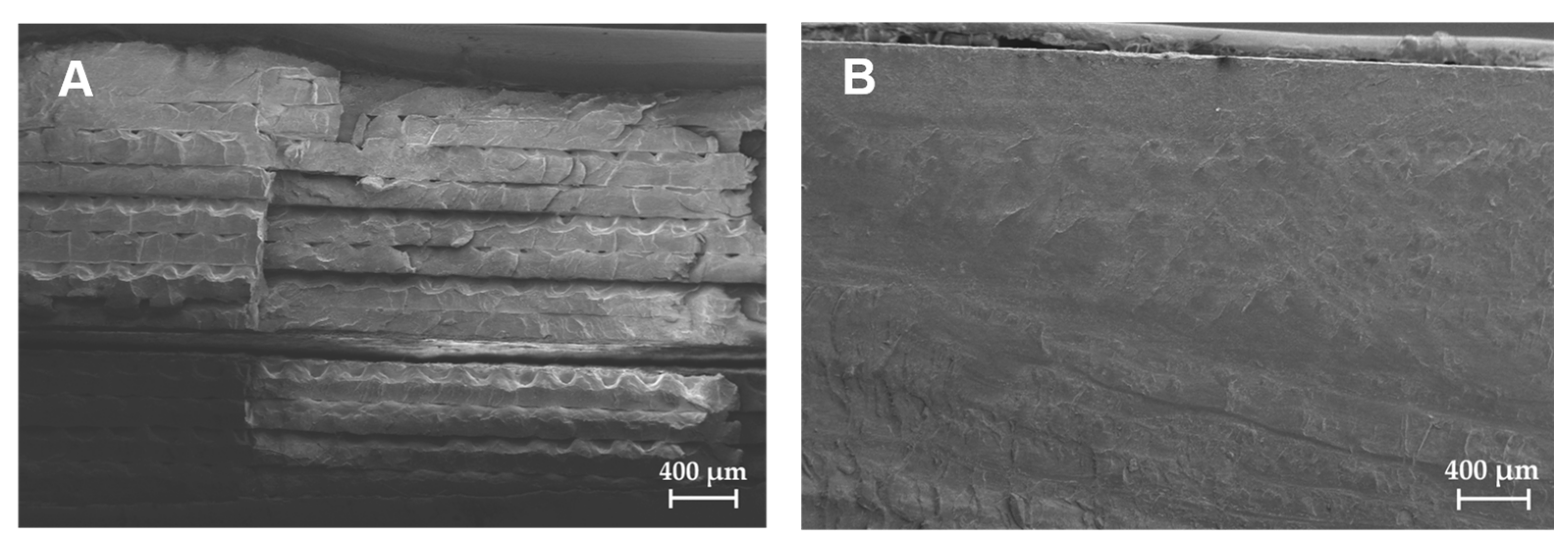
Notably, the correlation between the roughness and light transmission is not primarily related to light transmission. There are samples with high transmission despite high roughness and vice versa. The primary factor influencing this appears to be the internal structure of the samples. For instance, sample A, highlighted in Figure 2, had a low transmission of 40 ± 3%, despite its low roughness (Ra = 5.1 ± 0.4 µm). At the low printing speed of 20 mm s−1, the time required per layer is so long that the material cools down to a point where the subsequently deposited layers are not able to completely fuse anymore. This becomes clear by looking at the cross sections from samples A (left) and B (right) under the scanning electron microscope in Figure 3. A sample appears opaque when the inner structure has many air inclusions or is not homogeneously fused, leading to light scattering. In contrast, the surface roughness has only a small influence on the transmission. Based on these results, the parameters chosen to print the bioreactor were a printing speed of 40 mm s−1, a discharge rate of 80% and a building chamber temperature of 80 °C.
The cell culture test carried out with the printed SMMA showed that the material can be classified as non-critical regarding inhibitory or toxic substances that could migrate from the plastic to the culture broth, according to the criteria of the DECHEMA. The maximum VCD differs significantly less than the 10% specified in the guideline [22] and there is also no statistically significant difference in the maximum VCD (VCDWFI,SMMA = 3.84 ± 0.08 × 10⁶ cells mL−1, VCDWFI,Reference = 3.78 ± 0.12 × 10⁶ cells mL−1, VCDMedia,SMMA = 4.80 ± 0.09 × 10⁶ cells mL−1 and VCDMedia,Reference = 4.83 ± 0.05 × 10⁶ cells mL−1). The same applies to the other parameters examined.

3.2. Bioreactor Design and Assembly

The bioreactor was composed of four parts, manufactured from different materials, namely the main body (PMMA), the bottom plate (PMMA), the biomass sensor (acrylic resin) and the lid (polyamide). The main body, which was printed as described in chapter 2.1, featured a sizable opening on the side to facilitate the installation of the biomass sensor and two small holes to accommodate the attachment of pH and DO single use sensor spots (SP-HP5 and SP-PSt3, PreSens GmbH, Regensburg, Germany). The biomass sensor was printed separately with the resin AR-M2 using an Agilista 3200W (Keyence Corporation, Osaka, Japan). To accommodate the different sensing requirements of microbial and mammalian cultivations, two biomass sensor variants were created. The microbial version had an optical pathway of 1 mm, while the cell culture version had a pathway of 5 mm. The bottom plate, which features the cup that housed the agitator, was injection molded, due to the required precision and thin wall strength. The bottom plate and sensors were glued to the main body using Loctite EA M-31CL medical device epoxy adhesive (Henkel, Düsseldorf, Germany).
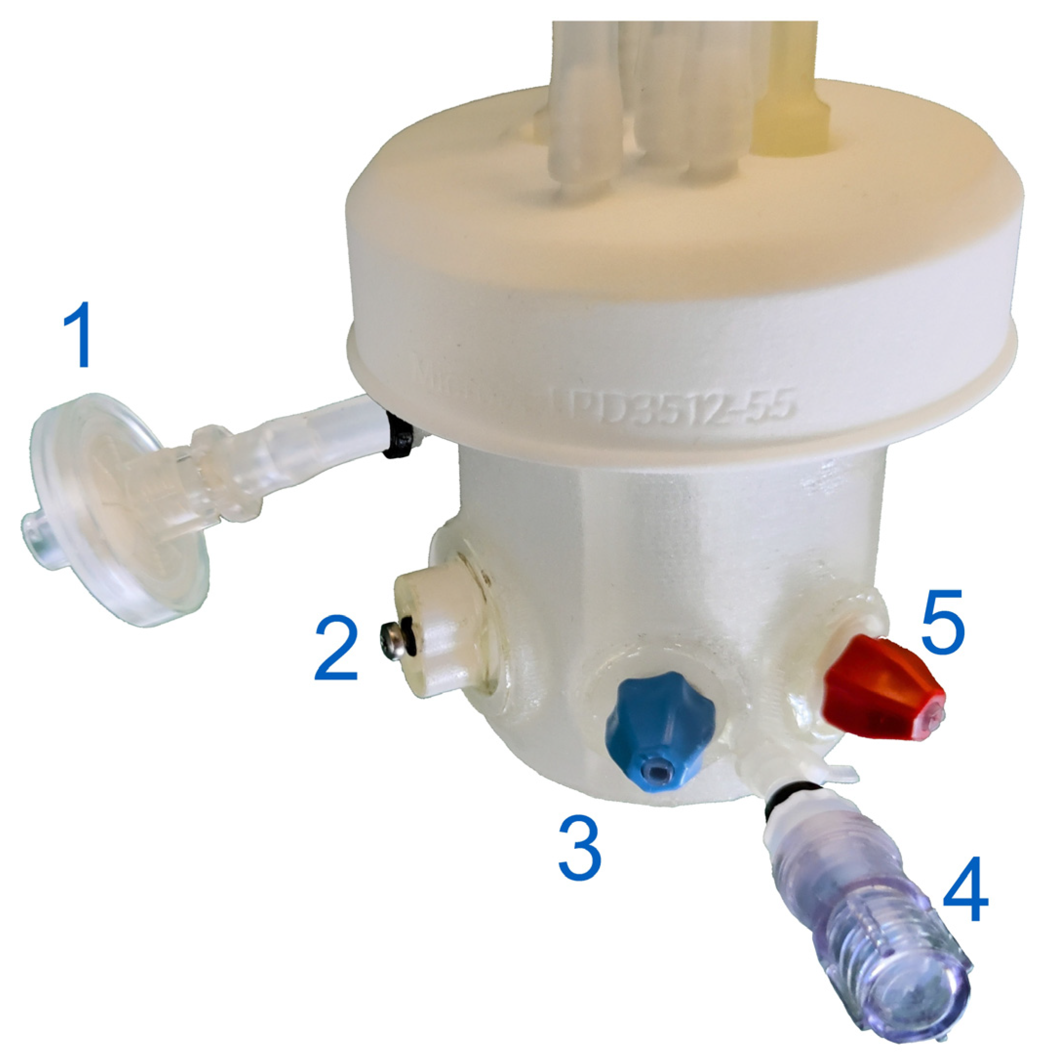
The top plate was manufactured with selective laser sintering (SLS) of polyamide and was based on the commercially available AppliFlex ST bioreactor (Getinge, Gothenburg, Sweden). It featured an internal thread, enabling it to be screwed onto the main body. An airtight seal was ensured with a rubber gasket inserted into the headplate. Before the top plate was screwed on, an LPI-30.7 mixer impeller (Levitronix, Zürich, Switzerland) was placed in the cup at the bottom of the bioreactor. Figure 4 depicts a schematic representation of the fully assembled bioreactor while Figure 5 presents a picture of the final product. Excluding the tubing, the bioreactor is approximately 100 mm tall, and the top plate of the bioreactor has an outer diameter of 75 mm. The vessel has an inner diameter of 51 mm, a wall strength of 1 mm and four baffles, with a width of 4 mm, that protrude 6 mm into the vessel. Measured from the bottom of the vessel, excluding the stirrer cup, the vessel has an internal height of 70 mm, and at its maximum working volume of 90 mL, the liquid level is at 53 mm.
As a final manufacturing step, the assembled bioreactors were sterilized. Since not all components were heat stable, this was performed with beta irradiation at 18 kGy. However, since sterile bioreactors were not strictly necessary for the intended microbial proof of concept cultivation, unsterilized bioreactors were used for the E. coli fed-batch cultivation.

3.3. Process Engineering Parameters

Using CFD, the flow profile was analyzed, and the speed-dependent specific power input was calculated. The analysis shows that at 180 rpm, hardly any vortex is formed (Figure 6a), whereas at 2000 rpm, a strong vortex formation is present (Figure 6b). The velocity peaks at the stirrer blades’ tips ( v t i p = 0.26 m s−1 and v t i p = 2.89 m s−1) and decreases radially. The fluid moves downward in the center of the reactor and also flows through the hole in the stirrer and the gap of the magnetic bearing.
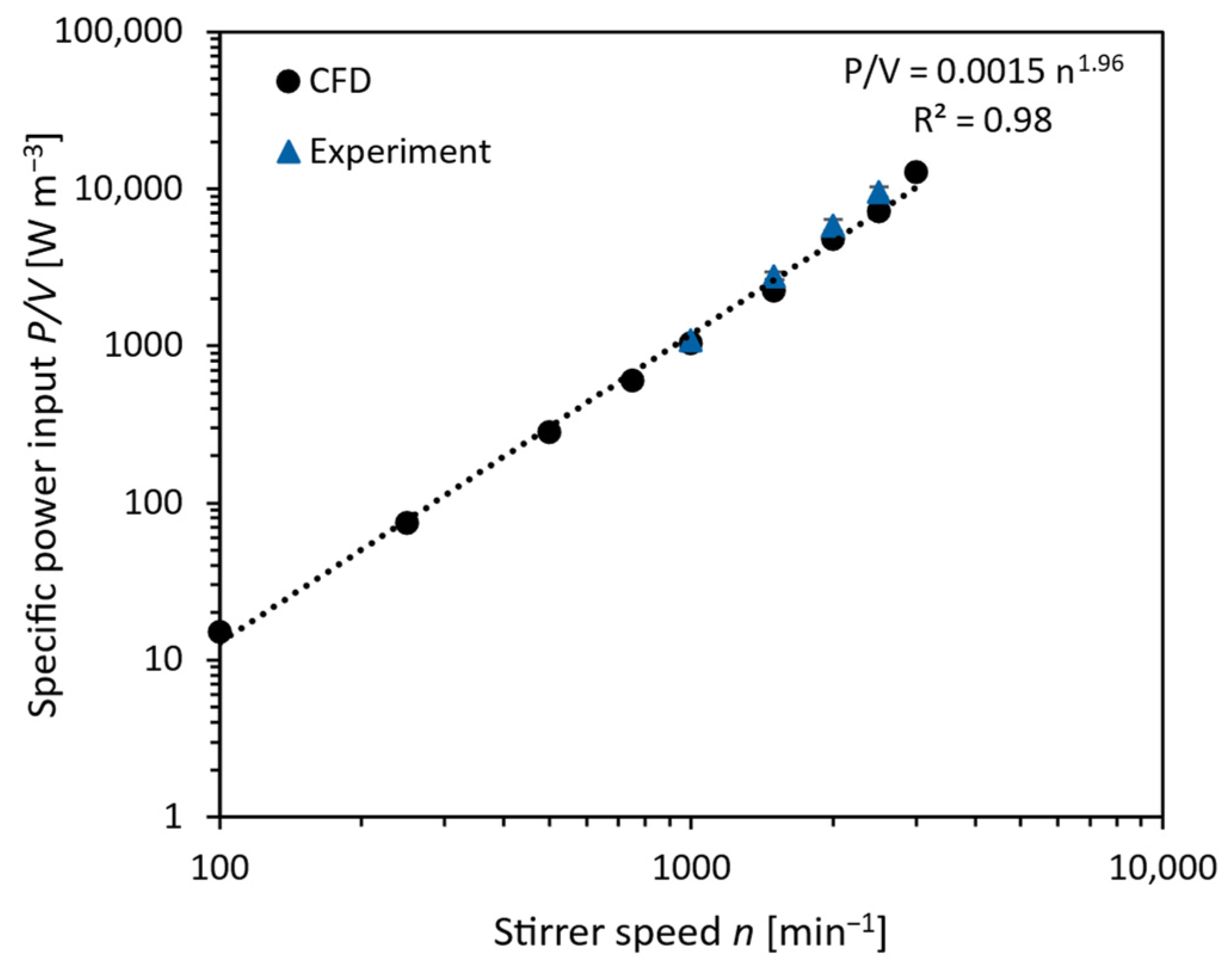
The specific power input is an allometric function of the stirrer speed, which is typical for stirred reactors. The CFD simulations show good agreement with the investigated experimental measurement range (Figure 7).
For CHO cell cultivation, a specific power input of 40 W m−3 was aimed for, aligning with typical CHO cultivations [30]. This was achieved with a stirrer speed of 180 rpm (39.5 W m−3). For the microbial cultivations, a stirrer speed of 2000 rpm was used, corresponding to a specific power input of 4427 W m−3. This is notably lower than the 14,300 W m−3 reported by Schirmer et al. [27], who used the same drive for an E. coli cultivation in a 2 L system. In comparison to classical drives, the employed specific power input is in the typical range, albeit at the lower range of the spectrum [31,32]. The stirrer speed’s limitation in this study was due to the reactor design, as extreme vertex formation at higher stirring speeds caused liquid to splash at the headplate, which could cause exhaust air filter blockage.
The experimentally determined mixing time was 2.8 ± 0.1 s at 180 rpm and 0.37 ± 0.1 s at 2000 rpm, aligning with typical mixing times for milliliter scale bioreactors and bearing similarity to the Ambr 250 bioreactor form Sartorius AG at equivalent stirrer tip speeds [33]. The kLa value of 2.6 ± 0.2 h−1 at 180 rpm is also within a normal range used for mammalian cell cultures [2,34]. At a stirrer speed of 2000 rpm (microbial cultivation conditions), the measured kLa value of 384 ± 22 h−1, is in the range of 300 h−1 to 745 h−1 which is generally sufficient for microbial cultivations [27]. Compared to Schirmer et al. [27], who performed cultivations with the same drive, the kLa value is more than 50% higher, even though the specific power input was only a third.

3.4. Sensor Design

The sensing scheme was based on the idea of combining independent sensors, which offers several advantages. By using multiple sensors, data continuity can be ensured through redundancy, and the combination of multiple sensors allows for more process control and insight. The sensors used in the bioreactor prototype were designed as individual ports that can be connected to the vessel. Using this approach, the ports can be developed and manufactured separately from the vessel body, allowing the different project partners to develop independently. The assembly, shown in Figure 8a, allowed for the inline measurement of pH, DO and biomass.
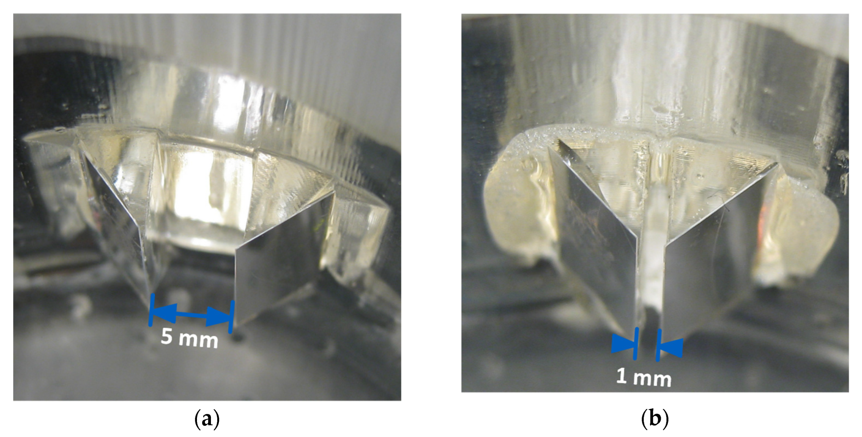
The biomass sensor was designed to mimic the established method of optical density measurement in cuvettes. In this vessel, two triangular prisms were placed to form a gap with a defined width (Figure 8b). Light with a peak wavelength of 605 nm is directed into the prism assembly at a 0° angle to the wall surface, and the light that passes through the sample is detected via a photodetector. By adjusting the distance between the prisms, it was possible to customize the optical pathway to suit the particular cultivated organism and therefore improve the accuracy and sensitivity of the measurement. Two different designs are depicted in Figure 9. Total reflection was ensured by adding aluminum foil to the sides of prisms inside the vessel.
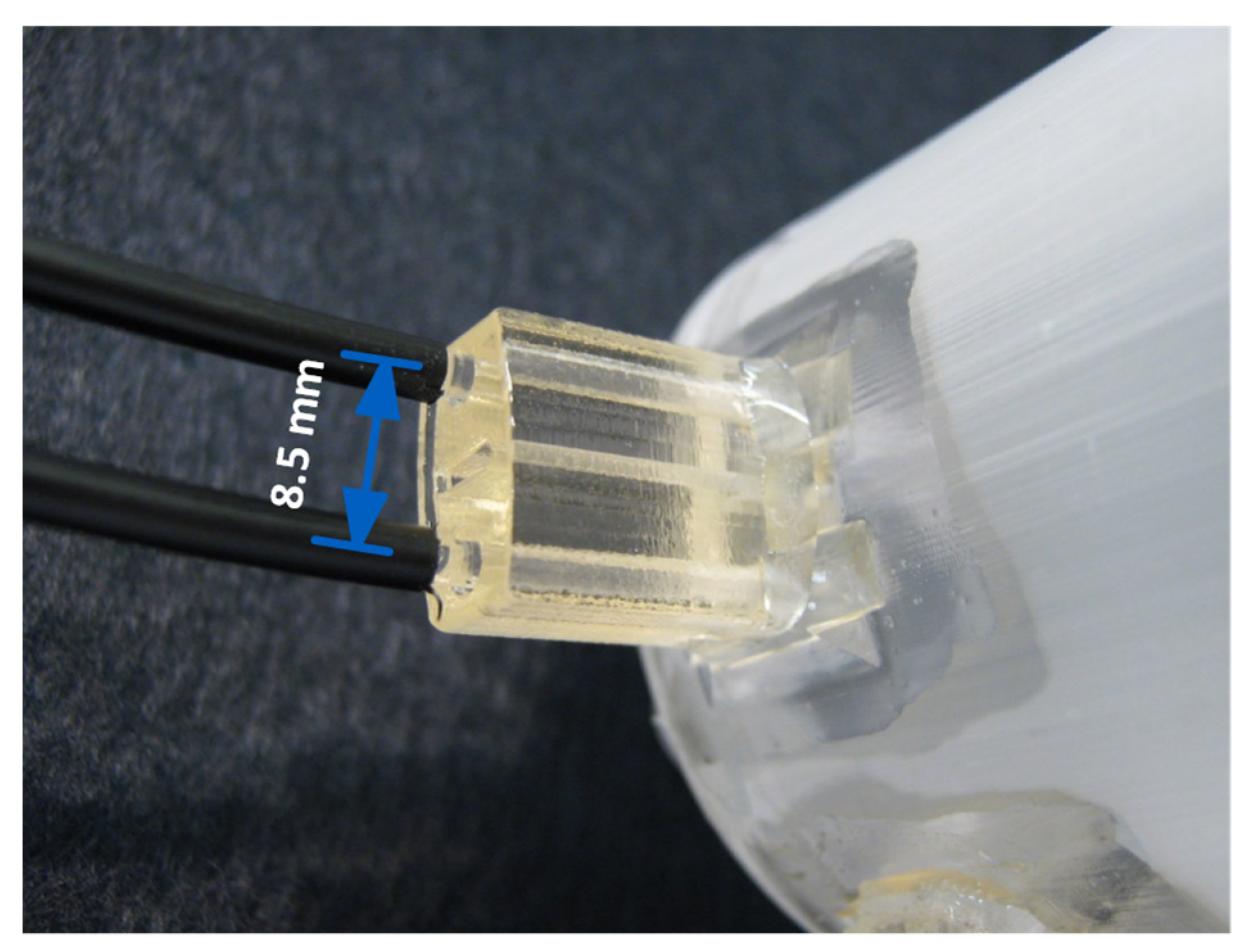
The sensor was connected to an optoelectronics board using polymer optical fibers, with a diameter of 2 mm, as shown in Figure 10. One fiber directed the light from the LED to the measurement gap and the other relayed the transmitted light to the photodetector.
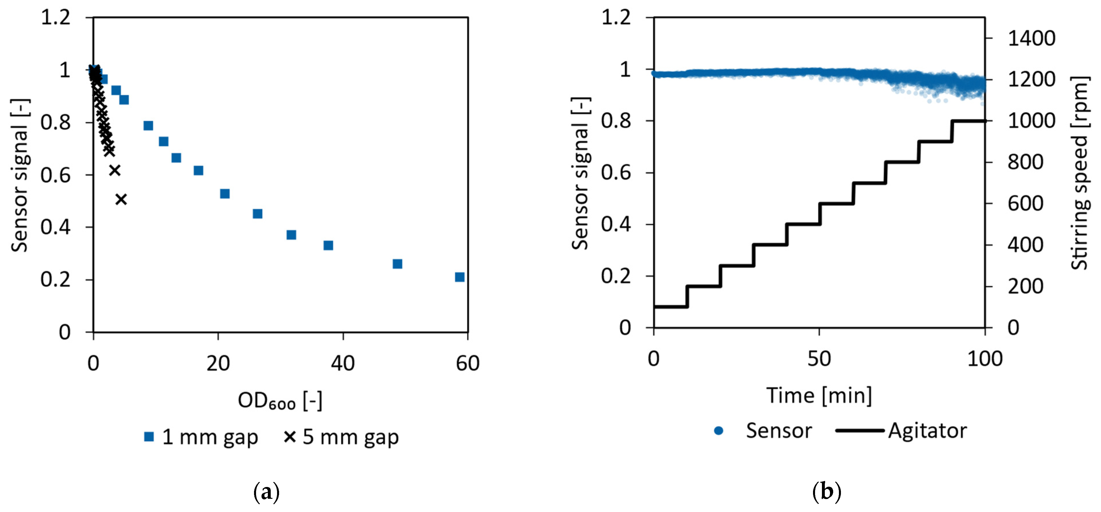
Baker’s yeast suspensions of various concentrations were measured with both optical pathway sizes. As can be seen in Figure 11a, there is a negative correlation between biomass concentration and raw-signal intensity, while the steepness of the sensor response depends on the gap size of the sensor. By changing the gap size, the sensitivity of the biomass sensor can be adjusted to the optical density range of interest, e.g., narrow gap ⇒ low sensitivity ⇒ high measurement range for microbial cultivations and big gap ⇒ high sensitivity ⇒ low measurement range for mammalian cultivations. The stability of the sensor signal under real-life conditions was investigated by measuring a yeast suspension with an OD600 of 10 with a sensor gap size of 1 mm at various stirring speeds ranging from 100 to 1000 rpm. As shown in Figure 11b, the noise level remains acceptable even at high stirring speeds.
The gap width of the biomass sensor not only has an influence on the measuring range, but also on the flow pattern. The extent of this influence was investigated using CFD for gap widths ranging from 0.25 mm to 5 mm. Ultimately, a gap width of 1 mm was selected for microbial cultivations and 5 mm for mammalian cultivations. Furthermore, the influence of the stirrer speed on the flow rate was investigated within a range of 100 rpm to 2000 rpm. The findings demonstrated that, within the investigated range, the flow rate increases linearly with both the gap width and the stirrer speed. For the cultivations with CHO cells (n = 180 rpm and w = 5 mm), a flow rate of 9.2 mL min−1 through the vertical biomass sensor gap (area 4 mm2) was calculated. For the E. coli cultivations (gap area 0.8 mm), the flow rate was 553 mL min−1 (n = 2000 rpm and w = 1 mm).

3.5. Cultivations

3.5.1. E. coli Proof of Concept Cultivation

For the E. coli cultivation, the bioreactor was inoculated with an OD600 of 1. A DO spike, which indicates that the substrates are depleted, was detected after 6.7 h. At this point, an OD600 of 23.2 was measured. Subsequently, the exponential feed was initiated and maintained until the process time reached 14 h. The peak CDW and OD600 achieved were 69 g L−1 and 204, respectively, which are somewhat lower than the values attained by Schirmer et al. in a similar process, where a CDW of 86.6 g L−1 and an OD600 of 262 were reported [27]. As depicted in Figure 12, the initiation of feeding causes an inflection point in the cell density curve, as the cell growth changes from one governed by a substrate surplus to glucose limited growth. The average cell specific growth rates were 0.49 h−1 and 0.39 h−1 for the batch- and feed-phase, respectively. The achieved growth rate during the feed-phase was very close to the targeted growth rate of 0.4 h−1.
Due to the different requirements for handling the samples, the OD600 values are deemed more accurate at low concentrations, while the CDW values are more trustworthy at higher cell densities. Therefore, the reported growth rate in the batch-phase was calculated based on OD600, while the fed-batch growth rate was calculated using the CDW data.
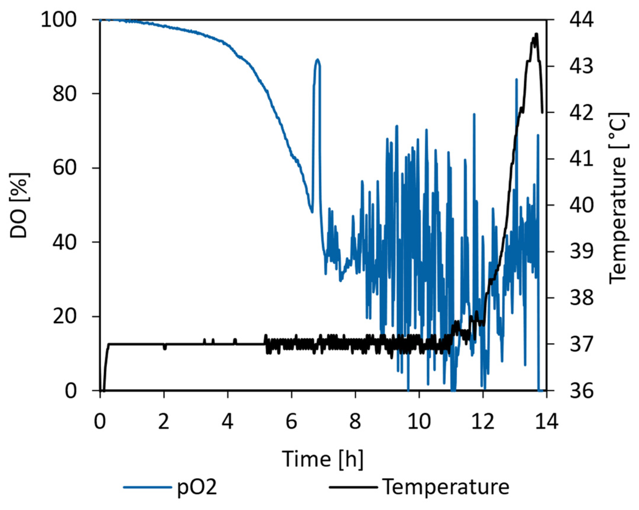
As can be seen in Figure 13, after process hour 11, the cooling capability of the temperature control unit was no longer sufficient to keep the vessel temperature at its setpoint of 37 °C, and the temperature started to rise. A peak temperature of 43.7 °C was recorded at 13.7 h. Subsequent to this peak, a metabolic slowdown induced a temperature reduction, and the process was concluded after the 14th process hour. Throughout the feed-phase, the DO was regulated to 40%. Although this regulation was not optimal, it is anticipated that no oxygen limitation occurred during the cultivation.
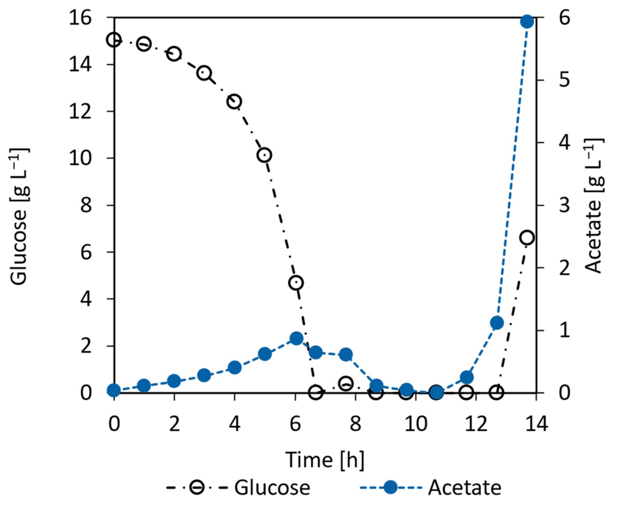
As can be seen in Figure 14, the glucose concentration remained close to zero during the feed-phase but sharply rose after the 13th hour. A small amount of acetate was formed during the batch-phase and subsequently consumed again in the feed-phase. Coinciding with the temperature rise at the end of the cultivation, the acetate concentration rose sharply to 6 g L−1.
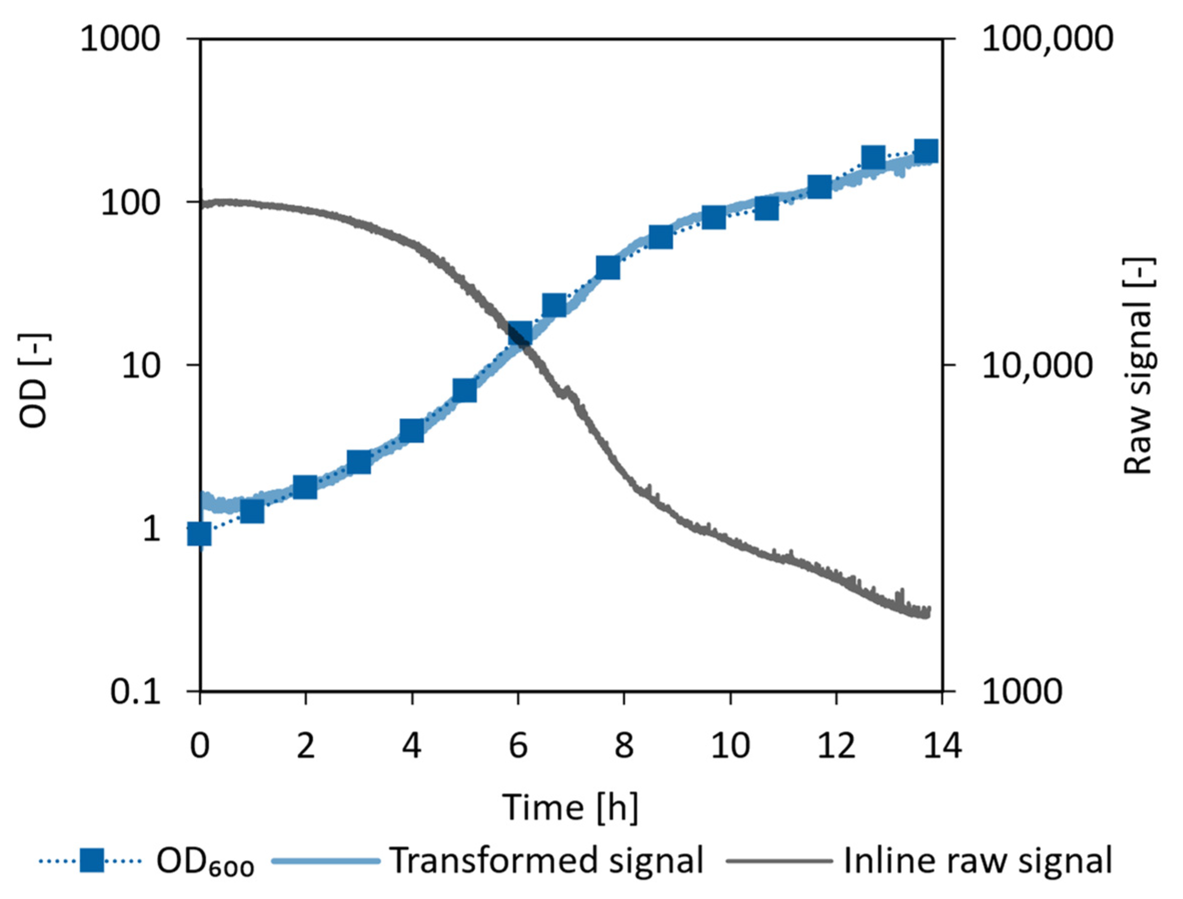
The inline biomass sensor performance can be seen in Figure 15. For the E. coli cultivation, an optical path length of 1 mm was used, and a data point was recorded every second. To filter out noise, a moving average calculation was applied over nine datapoints.
The raw signal of the biomass sensor could be fitted to the offline OD600 measurements using Equation (9) with the parameters listed in Table 2. The three-parameter fit resulted in a coefficient of determination of 0.985. A linear fit after exponential transformation was also investigated and resulted in a good fit for offline OD values < 30. A deviation at higher cell densities was expected, as the light attenuation is not linear anymore at this range for an optical path length of 1 mm. For this reason, the more complex and potentially less robust 3-parameter equation was chosen, ensuring a good fit across the whole measurement range.
OD i ( BM r a w ) = BM r a w 2     c + BM r a w 1   b + a

3.5.2. CHO Proof of Concept Cultivation

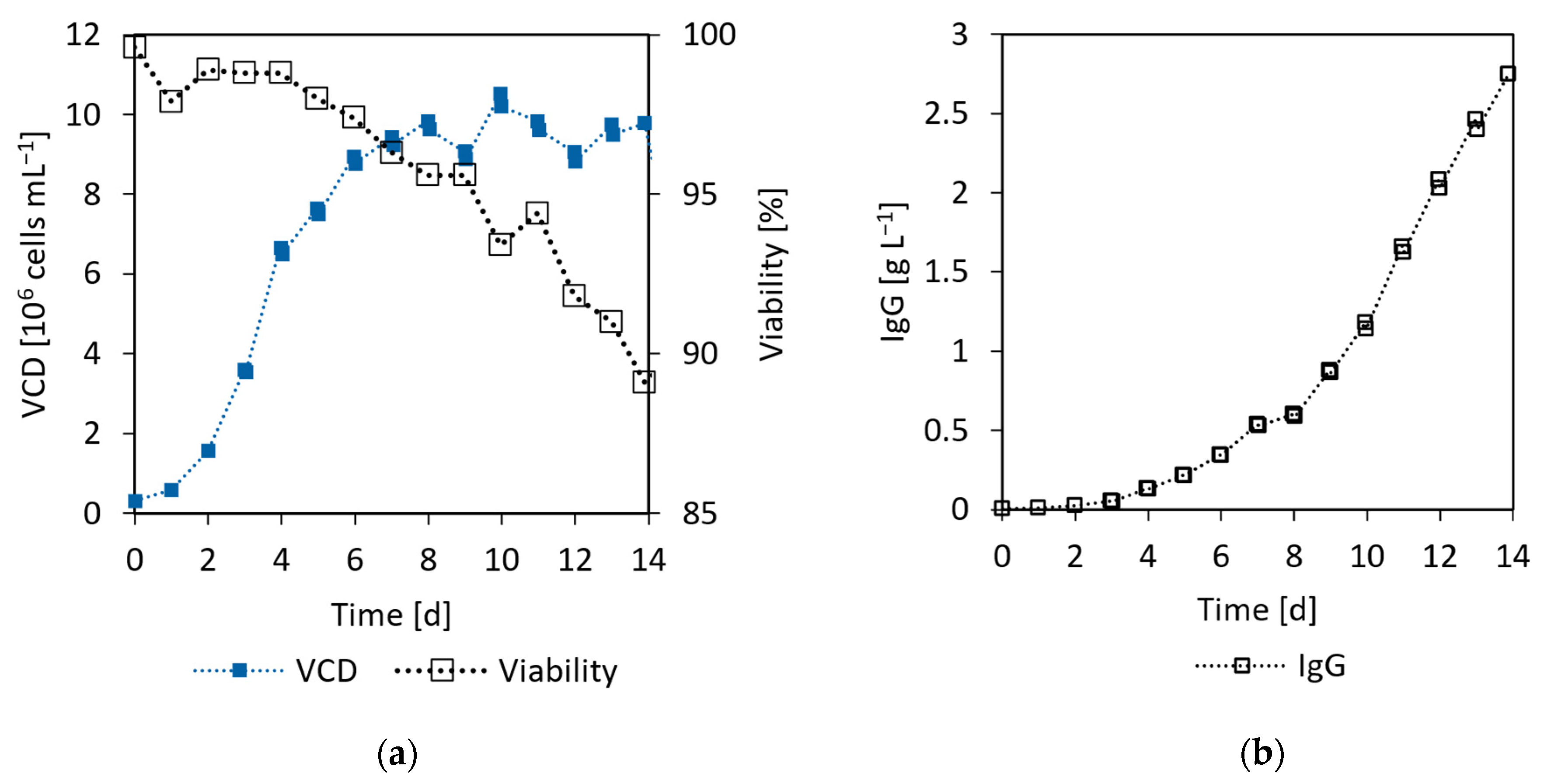
The cells grew exponentially from day 0 to day 4, as can be seen in Figure 16a. During the stationary phase (D6–D14) the VCD was approximately 10 × 106 cells mL−1. The viability declined steadily during the stationary phase and reached 89% on the harvest day. A maximum IgG concentration of 2.75 g L−1 was reached on day 14. As can be seen in Figure 16b, the majority of IgG was formed between day 10 and 14. While the VCD and titer concentrations attained were somewhat below modern literature values of similar processes [35], the focus was on the feasibility of 3D printed bioreactors, which was clearly demonstrated.
In Figure 17a, it can be seen that the glucose concentration decreased to 2.95 g L−1 before the daily feed was started on D3. The substrate and metabolite concentrations after the feed addition were not measured, but rather calculated based on the feed medium composition and the volume of added glucose solution. The maximum recorded lactate concentration was 1.83 g L−1 on D5, after which it decreased again due to the efficient lactate metabolism of the cultivated cell line. The minimum glutamine concentration was at D6 of the cultivation and increased again towards the end of the cultivation (Figure 17b). While the feed medium does not contain any glutamine, it contains glutamate, which can be used by the cells to form glutamine. The ammonium concentration rapidly increased during the growth phase and plateaued in the early stationary phase, before increasing again to 21.2 mmol L−1 at the end of the cultivation.
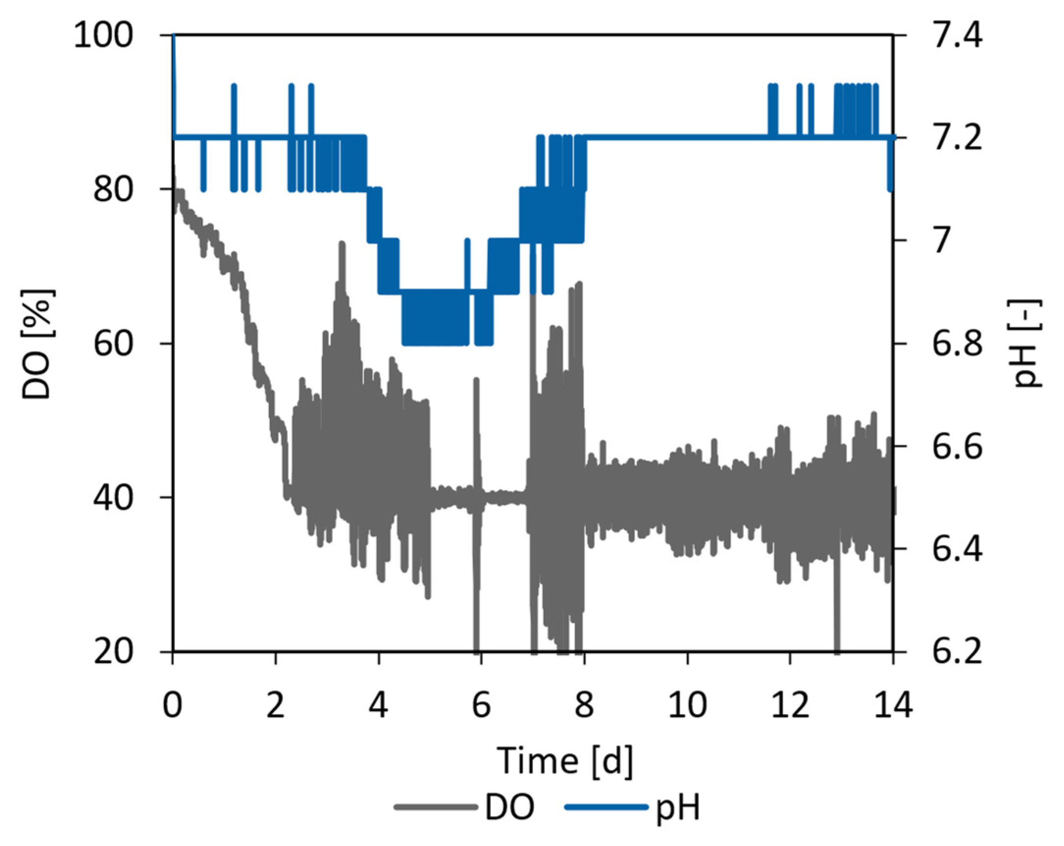
Over the first 2.5 days, the DO decreased to the targeted 40%, as can be seen in Figure 18. This level was maintained for the remainder of the cultivation through oxygen sparging. The pH could be regulated to its setpoint of 7.2 via CO2 addition for the first 3.7 days, but then fell to 6.8 due to lactate accumulation. As a result of lactate consumption, the pH rose again to its setpoint at D8 and could be regulated for the remainder of the cultivation.
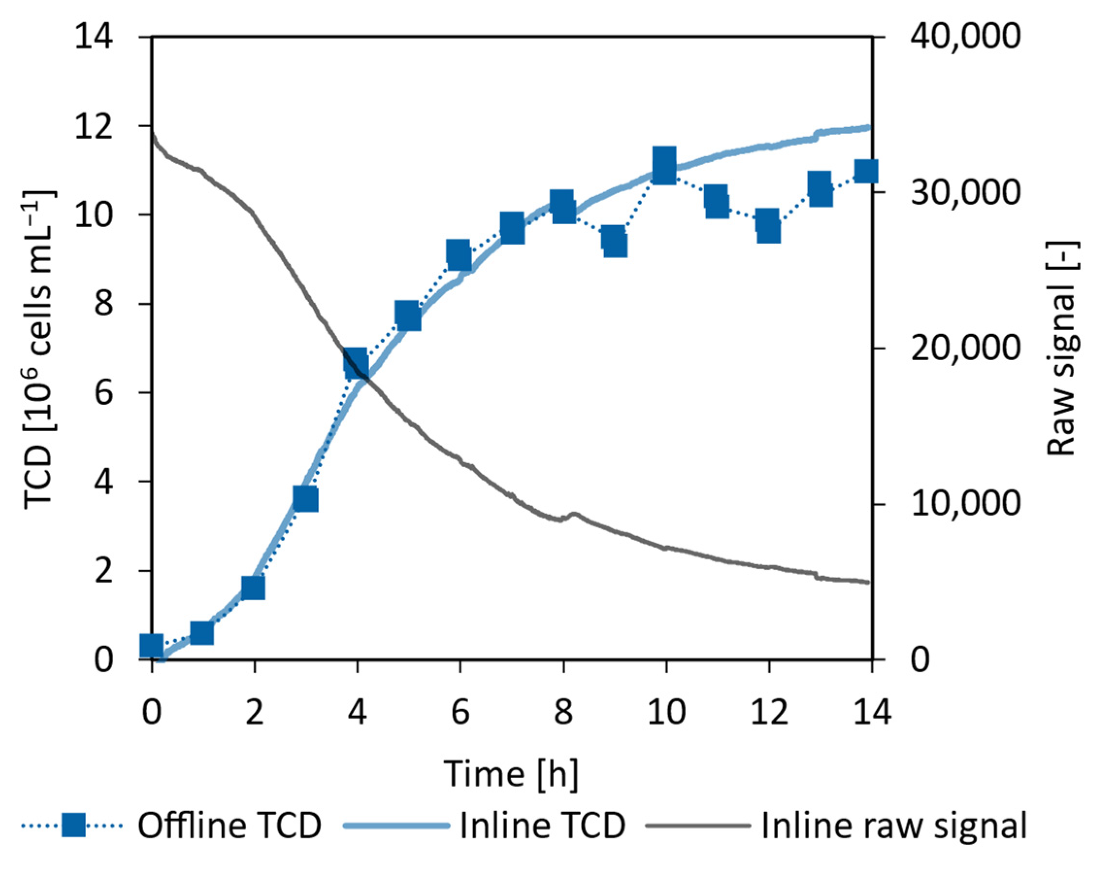
For the CHO cultivation, an optical path length of 5 mm was chosen for the inline biomass sensor. A measurement was taken every 30 s and nine measurements were combined using a moving average filter, resulting in the gray curve displayed in Figure 19.
In contrast to the E. coli cultivation, optical density is not a typical process parameter measured in mammalian cultivations to assess biomass. Instead, the focus normally lies on the VCD. Since the employed optical measurement is based on transmission/attenuation of light, viable and dead cells will produce similar signals and cannot be distinguished. Therefore, efforts were made to correlate the inline signal with the TCD measured offline. A satisfactory fit could be achieved using the quadratic Equation (10) with the fit parameters listed in Table 3, resulting in the curve depicted in Figure 19. The fit has a coefficient of determination of 0.961 over the whole cultivation and one of 0.989 during the growth phase until day 8. The overshoot in the later part of the stationary phase can be explained by the formation of cell debris through cell lysis, which is only detected via the optical inline sensor and not with the offline cell counter. However, the inline sensor has the advantage of not being influenced by sampling inhomogeneities and variability during sample preparation, which leads to a smoother, more accurate biomass estimation.
TCD i ( BM r a w ) = BM r a w 2 c + BM r a w b + a  
A better fit could potentially be found by using a more complex formula and by including the cell diameter, since the average cell diameter increased from 13 µm to 21 µm during the cultivation, and larger cells are thought to attenuate light more strongly.

4. Conclusions

While the performance of both the E. coli and CHO fed-batch cultivation fell short of benchmark values established in the literature for optimized processes, the studies underscored the viability of AM in manufacturing bioreactors that are suitable for mammalian and microbial cultivation. Importantly, there was no indication of growth inhibitory substances leaching from the vessel material into the culture medium.
The biochemical engineering investigation of the 90 mL bioreactor revealed that the mixing and oxygen transfer capabilities of the system are satisfactory for a broad range of microbial and mammalian cultivations. The integrated pH and DO sensors facilitated precise process monitoring and control, while the developed inline biomass sensor proved to be applicable in both mammalian and microbial cultivations. Using a three-parameter fit, the inline biomass measurements could be transformed to inline TCD and OD600 values. This transformation, showing satisfactory agreement with the corresponding offline measurements, enabled real time monitoring of the growth phase. However, a hurdle which needs to be overcome is the variability between individual biomass sensors, so that the established fit functions can easily be applied to multiple cultivations with only minor adjustments. Additionally, sensor fouling, which could be caused by biofilm formation, should be investigated to exclude sensor drift as a source of error.
By applying the gained insights, the system performance can undoubtedly be improved by, for example, increasing the system’s cooling capabilities which limited the E. coli process towards the end of the cultivation. Furthermore, considering the current prototype’s multi-piece assembly, which introduces manufacturing complications and inherent leakage risks, future iterations should explore monolithic bioreactor manufacturing.
To utilize the full potential of AM in bioreactor manufacturing, the vessel geometry needs to be viewed as a parameter that can be optimized based on the needs of the experimenter, which is not restricted by the limitations of classical manufacturing technologies like injection molding. Access ports and lines to and from the bioreactor can be placed wherever suitable for the intended experiment series and the focus can be shifted from the one size fits all concept of classical bioreactors to one of increased customizability and flexibility.

Author Contributions

Conceptualization, S.L.S. and S.S.; formal analysis, S.L.S. and S.S.; investigation, S.L.S., S.S., A.S., M.R., G.T.J., S.K. and J.G.; resources, T.N. and G.T.J.; writing—original draft preparation, S.L.S., S.S., A.S., M.R. and G.T.J.; writing—review and editing, S.K., T.N. and D.E.; visualization, S.L.S., S.S., M.R., A.S., S.K. and G.T.J.; supervision, G.T.J. and D.E.; project administration, G.T.J. and D.E.; funding acquisition, T.N., G.T.J. and D.E. All authors have read and agreed to the published version of the manuscript.

Funding

This research was funded by Eureka Eurostars grant number E!113750. The APC was funded by ZHAW, Zurich University of Applied Sciences.

Data Availability Statement

Data are contained within the article.

Acknowledgments

We would like to thank Timo Walvoort and Frits van den Berg from Getinge for their valuable input during the project and the writing of this manuscript. Also, we would like to thank Jason Parry (ZHAW) for proofreading.

Conflicts of Interest

Author Gernot Thomas John was employed by the company PreSens Precision Sensing GmbH. The authors Andressa Seefeldt, Simon Kastl, Julia Gensel and Thomas Neumeyer were employed by the company Neue Materialien Bayreuth GmbH. The remaining authors declare that the research was conducted in the absence of any commercial or financial relationships that could be construed as a potential conflict of interest.

Abbreviations

AMAdditive manufacturing
APFArburg Plastics Freeforming
CDWCell dry weight
CFDComputational fluid dynamics
CHOChinese hamster ovary
DODissolved oxygen
EOMElectro-optical module
IgGImmunoglobulin G
SMMAStyrene methyl methacrylate
SLSSelective laser sintering
TCDTotal cell density
VCDViable cell density
WFIWater for injection

Nomenclature

Latin symbols
aModel parameter in Equations (9) and (10)[-]
BMrawBiomass sensor raw signal[-]
bModel parameter in Equations (9) and (10)[-]
cModel parameter in Equations (9) and (10)[-]
cConcentration[g L−1]
C CDW / OD 600 Conversion factor [g L−1]
FFeed rate[g h−1]
F Surface tension force[N]
g Gravitational acceleration[m s−2]
IElectric current[A]
kLaVolumetric oxygen mass transfer coefficient[h−1]
KtMotor constant[N cm A−1]
MMoment[N m]
nStirring speed[rpm]
P/VSpecific power input[W m−3]
RaAverage surface roughness[µm]
tTime[h]
v Velocity[m s−1]
v t i p Tip speed[m s−1]
VVolume[m3]
wWidth[mm]
Yx/sYield[g g−1]
Greek symbols
α Volume fraction[-]
θMixing time[s]
κ Local interface curvature[m−1]
µSpecific growth rate[h−1]
υ Kinematic viscosity[m2 s−1]
ρ Density[kg m−3]
σ Surface tension[N m−1]
ΧPhysical properties[-]

References

  1. Sandner, V.; Pybus, L.P.; McCreath, G.; Glassey, J. Scale-Down Model Development in Ambr Systems: An Industrial Perspective. Biotechnol. J. 2019, 14, 1700766. [Google Scholar] [CrossRef] [PubMed]
  2. Xu, P.; Clark, C.; Ryder, T.; Sparks, C.; Zhou, J.; Wang, M.; Russell, R.; Scott, C. Characterization of TAP Ambr 250 Disposable Bioreactors, as a Reliable Scale-down Model for Biologics Process Development. Biotechnol. Prog. 2017, 33, 478–489. [Google Scholar] [CrossRef] [PubMed]
  3. Hsu, W.-T.; Aulakh, R.P.S.; Traul, D.L.; Yuk, I.H. Advanced Microscale Bioreactor System: A Representative Scale-down Model for Bench-Top Bioreactors. Cytotechnology 2012, 64, 667–678. [Google Scholar] [CrossRef] [PubMed]
  4. Zhang, X.; Moroney, J.; Hoshan, L.; Jiang, R.; Xu, S. Systematic Evaluation of High-Throughput Scale-down Models for Single-Use Bioreactors (SUB) Using Volumetric Gas Flow Rate as the Criterion. Biochem. Eng. J. 2019, 151, 107307. [Google Scholar] [CrossRef]
  5. Junne, S.; Neubauer, P. How Scalable and Suitable Are Single-Use Bioreactors? Curr. Opin. Biotechnol. 2018, 53, 240–247. [Google Scholar] [CrossRef]
  6. Oosterhuis, N.M.G.; Junne, S. Design, Applications, and Development of Single-Use Bioreactors. In Bioreactors; John Wiley & Sons, Ltd.: Hoboken, NJ, USA, 2016; pp. 261–294. ISBN 978-3-527-68336-9. [Google Scholar]
  7. Nogueira, D.E.S.; Cabral, J.M.S.; Rodrigues, C.A.V. Single-Use Bioreactors for Human Pluripotent and Adult Stem Cells: Towards Regenerative Medicine Applications. Bioengineering 2021, 8, 68. [Google Scholar] [CrossRef]
  8. Kaiser, S.C. An Approach for Rapid Manufacture and Qualification of a Single-Use Bioreactor Prototype. In Single-Use Technology in Biopharmaceutical Manufacture; Eibl, R., Eibl, D., Eds.; Wiley: Hoboken, NJ, USA, 2019; pp. 235–246. ISBN 978-1-119-47783-9. [Google Scholar]
  9. Priyadarshini, B.M.; Dikshit, V.; Zhang, Y. 3D-Printed Bioreactors for In Vitro Modeling and Analysis. IJB 2020, 6, 267. [Google Scholar] [CrossRef]
  10. Sharma, R.; Harrison, S.T.L.; Tai, S.L. Advances in Bioreactor Systems for the Production of Biologicals in Mammalian Cells. ChemBioEng Rev. 2022, 9, 42–62. [Google Scholar] [CrossRef]
  11. Wang, X.-D.; Wolfbeis, O.S. Fiber-Optic Chemical Sensors and Biosensors (2008–2012). Anal. Chem. 2013, 85, 487–508. [Google Scholar] [CrossRef]
  12. Beal, J.; Farny, N.G.; Haddock-Angelli, T.; Selvarajah, V.; Baldwin, G.S.; Buckley-Taylor, R.; Gershater, M.; Kiga, D.; Marken, J.; Sanchania, V.; et al. Robust Estimation of Bacterial Cell Count from Optical Density. Commun. Biol. 2020, 3, 512. [Google Scholar] [CrossRef]
  13. Stevenson, K.; McVey, A.F.; Clark, I.B.N.; Swain, P.S.; Pilizota, T. General Calibration of Microbial Growth in Microplate Readers. Sci. Rep. 2016, 6, 38828. [Google Scholar] [CrossRef] [PubMed]
  14. Harris, D.C.; Lucy, C.A. Quantitative Chemical Analysis, 9th ed.; W.H. Freeman & Company: New York, NY, USA, 2016; ISBN 978-1-4641-3538-5. [Google Scholar]
  15. AARBURG Gmbh Whitepaper: Droplets to the Beat of Milliseconds, Arburg Plastic Freeforming: Current Investigations on Part Optimization. Kunststoffe Int. 2018, 11, 15–21.
  16. Volpato, N.; Kretschek, D.; Foggiatto, J.A.; Gomez Da Silva Cruz, C.M. Experimental Analysis of an Extrusion System for Additive Manufacturing Based on Polymer Pellets. Int. J. Adv. Manuf. Technol. 2015, 81, 1519–1531. [Google Scholar] [CrossRef]
  17. Rehfeld, J.S.; Kuhnke, L.M.; Ude, C.; John, G.T.; Beutel, S. Investigation and Evaluation of a 3D-printed Optical Modified Cultivation Vessel for Improved Scattered Light Measurement of Biotechnologically Relevant Organisms. Eng. Life Sci. 2023, 23, e2300204. [Google Scholar] [CrossRef] [PubMed]
  18. Reichert, T.; Nussbaumer, T.; Kolar, J.W. Bearingless 300-W PMSM for Bioreactor Mixing. IEEE Trans. Ind. Electron. 2011, 59, 1376–1388. [Google Scholar] [CrossRef]
  19. Zhong, J.-J. Bioreactor Engineering. In Comprehensive Biotechnology; Elsevier: Amsterdam, The Netherlands, 2011; pp. 165–177. ISBN 978-0-08-088504-9. [Google Scholar]
  20. Hammond, M.; Nunn, H.; Rogers, G.; Lee, H.; Marghitoiu, A.-L.; Perez, L.; Nashed-Samuel, Y.; Anderson, C.; Vandiver, M.; Kline, S. Identification of a Leachable Compound Detrimental to Cell Growth in Single-Use Bioprocess Containers. PDA J. Pharm. Sci. Technol. 2013, 67, 123–134. [Google Scholar] [CrossRef]
  21. INEOS Styrolution NAS 30 Styrene Methyl Methacrylate Technical Datasheet. 2016. Available online: https://www.ineos-styrolution.com/Product/NAS_NAS-30_SKU401000260276.html (accessed on 28 April 2023).
  22. Eibl, R.; Steiger, N.; Fritz, C.; Eisenkrätzer, D.; Bär, J.; Müller, D.; Eibl, D. Recommendation for Leachables Studies-Standardized Cell Culture Test for the Early Identification of Critical Films, 1st ed.; DECHEMA: Frankfurt am Main, Germany, 2014; ISBN 978-3-89746-149-9. [Google Scholar]
  23. Hirt, C.W.; Nichols, B.D. Volume of Fluid (VOF) Method for the Dynamics of Free Boundaries. J. Comput. Phys. 1981, 39, 201–225. [Google Scholar] [CrossRef]
  24. Menter, F. Zonal Two Equation K-w Turbulence Models for Aerodynamic Flows. In Proceedings of the 23rd Fluid Dynamics, Plasmadynamics, and Lasers Conference, Orlando, FL, USA, 6 July 1993; American Institute of Aeronautics and Astronautics: Reston, VA, USA, 1993. [Google Scholar]
  25. Roache, P.J. Perspective: A Method for Uniform Reporting of Grid Refinement Studies. J. Fluids Eng. 1994, 116, 405–413. [Google Scholar] [CrossRef]
  26. Bauer, I.; Dreher, T.; Eibl, D.; Glöckler, R.; Husemann, U.; John, G.T.; Kaiser, S.C.; Kampeis, P.; Kauling, J. Recommendations for Process Engineering Characterisation of Single-Use Bioreactors and Mixing Systems by Using Experimental Methods; DECHEMA: Frankfurt am Main, Germany, 2020; ISBN 978-3-89746-227-4. [Google Scholar]
  27. Schirmer, C.; Nussbaumer, T.; Schöb, R.; Pörtner, R.; Eibl, R.; Eibl, D. Development, Engineering and Biological Characterization of Stirred Tank Bioreactors. In Biopharmaceuticals; Yeh, M.-K., Chen, Y.-C., Eds.; InTech: London, UK, 2018; ISBN 978-1-78923-718-4. [Google Scholar]
  28. Schirmer, C.; Dreher, T.; Leupold, M.; Glaser, R.; Castan, A.; Brown, J.; Eibl, D.; Glöckler, R. Recommendation for Biological Evaluation of Bioreactor Performance for Microbial Processes; DECHEMA Biotechnologie: Frankfurt am Main, Germany, 2019; ISBN 978-3-89746-217-5. [Google Scholar]
  29. Biener, R.; Steinkämper, A.; Hofmann, J. Calorimetric Control for High Cell Density Cultivation of a Recombinant Escherichia Coli Strain. J. Biotechnol. 2010, 146, 45–53. [Google Scholar] [CrossRef]
  30. Xu, S.; Hoshan, L.; Jiang, R.; Gupta, B.; Brodean, E.; O’Neill, K.; Seamans, T.C.; Bowers, J.; Chen, H. A Practical Approach in Bioreactor Scale-up and Process Transfer Using a Combination of Constant P / V and Vvm as the Criterion. Biotechnol. Prog. 2017, 33, 1146–1159. [Google Scholar] [CrossRef]
  31. Ali, S.; Perez-Pardo, M.A.; Aucamp, J.P.; Craig, A.; Bracewell, D.G.; Baganz, F. Characterization and Feasibility of a Miniaturized Stirred Tank Bioreactor to Perform E. Coli High Cell Density Fed-Batch Fermentations. Biotechnol. Prog. 2012, 28, 66–75. [Google Scholar] [CrossRef] [PubMed]
  32. Knabben, I.; Regestein, L.; Marquering, F.; Steinbusch, S.; Lara, A.R.; Büchs, J. High Cell-Density Processes in Batch Mode of a Genetically Engineered Escherichia Coli Strain with Minimized Overflow Metabolism Using a Pressurized Bioreactor. J. Biotechnol. 2010, 150, 73–79. [Google Scholar] [CrossRef] [PubMed]
  33. Ruhl, S.; Zahnow, C.; Dreher, T.; Bargh, N.; Husemann, U.; Greller, G. Superior Scalability of a Single-Use Bioreactor Family from 0.25 to 2000 L. Sartorius 2017. Available online: https://www.sartorius.com/download/921544/ambr-biostat-superior-scalability-poster-en-sartorius-data.pdf (accessed on 28 April 2023).
  34. Nienow, A.W. Reactor Engineering in Large Scale Animal Cell Culture. Cytotechnology 2006, 50, 9–33. [Google Scholar] [CrossRef] [PubMed]
  35. Müller, J.; Ott, V.; Weiss, N.; Neubauer, P.; Eibl, D.; Eibl, R. Process Intensification Using a One-Step Inoculum Production and High-Seeded Fed-Batch Processes. Chem. Ing. Tech. 2022, 94, 1977–1984. [Google Scholar] [CrossRef]
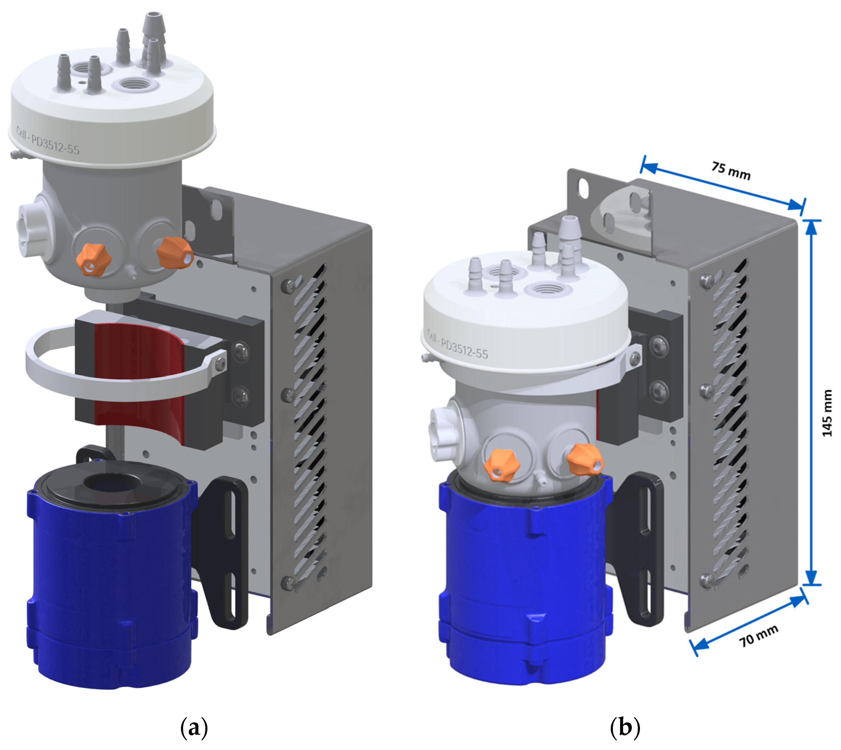
Figure 1. 3D printed bioreactor mounted on a modified commercial my-Control temperature control module (metallic gray) and a PMS-i30 mixer drive (blue). Exploded (a) and assembled (b) view. Tubing and cabling are omitted for clarity reasons. The bioreactor is affixed to the machined heat transfer block (dark gray) with a Velcro strip.
Processes 11 03231 g001
Figure 2. Surface roughness (Ra) as a function of the light transmission for samples printed with different printing speeds, discharge rates and building chamber temperatures. The highlighted samples were printed with the following printing speed, discharge rate and building chamber temperature: A: [20 mm s−1; 80%; 80 °C], B: [40 mm s−1; 80%; 90 °C], C: [60 mm s−1; 80%; 80 °C].
Processes 11 03231 g002
Figure 3. Scanning electron microscope images of cross sections of planar samples with (A) low transmission (40%) and (B) high transmission (80%).
Processes 11 03231 g003
Figure 4. 3D model of the bioreactor. Shown are the off-gas line (1), several liquid addition ports (2), two 8 mm ports for the insertion of classical probes (3), thermowell (4), the open pipe sparger used for the Escherichia coli cultivations (5), the overlay aeration port (6), the baffle-sparger (7), the levitating impeller (8), the pH and dissolved oxygen (DO) spots (9), the submerged sampling port (10) and the biomass sensor (11). From the bottom to the top plate, the reactor is approximately 100 mm tall, and the middle section has an outer diameter of 53 mm.
Processes 11 03231 g004
Figure 5. Fully assembled bioreactor. Visible are the baffle aeration connection (1), biomass sensor (2), DO sensor (3), sampling port (4) and the pH sensor (5).
Processes 11 03231 g005
Figure 6. Velocity profiles with line integral convolution representation. (a) Configuration with a stirrer speed of 180 rpm which was used for the Chinese hamster ovary cell (CHO) cultivations. (b) Microbial configuration with a stirrer speed of 2000 rpm.
Processes 11 03231 g006
Figure 7. Specific power input as a function of the stirrer speed. Measured and simulated values.
Processes 11 03231 g007
Figure 8. (a) All sensors were attached to separate ports of the vessel. The pH and oxygen electro-optical modules (EOM) were connected to the bioprocess controller while the biomass was connected to a computer. (b) Triangular prisms enabled different path lengths to adjust to different cultures.
Processes 11 03231 g008
Figure 9. Internal part of optical biomass sensor with a pathway of (a) 5 mm and (b) 1 mm. Aluminum foil was attached to the outer surface of the prisms to improve reflection.
Processes 11 03231 g009
Figure 10. External part of the optical biomass sensor with two installed polymer optical fibers that are spaced 8.5 mm apart.
Processes 11 03231 g010
Figure 11. (a) Normalized optical biomass sensor response for yeast suspensions with different OD600 values. (b) Influence of stirring on the biomass sensor noise level.
Processes 11 03231 g011
Figure 12. Logarithmic representation of cell dry weight (CDW) and OD600 curve of the E. coli fed-batch. The switch between batch- and feed-phase is indicated by a dashed line.
Processes 11 03231 g012
Figure 13. DO and temperature curve of E. coli fed-batch. The DO peak indicating the end of the batch-phase is visible at 6.7 h.
Processes 11 03231 g013
Figure 14. Glucose and acetate concentration curves of the E. coli fed-batch. The glucose depletion coincides with the start of the feed-phase.
Processes 11 03231 g014
Figure 15. Inline raw and transformed signal from the 1 mm optical biomass sensor used in E. coli cultivation.
Processes 11 03231 g015
Figure 16. (a) Viable cell density (VCD) and viability of CHO cultivation. (b) Immunoglobulin G (IgG) concentration of the CHO cultivation.
Processes 11 03231 g016
Figure 17. (a) Glucose and lactate concentration of CHO cultivation. (b) Glutamine and ammonium concentration of CHO cultivation. The spikes are due to the daily addition of feed medium which was started on D3.
Processes 11 03231 g017
Figure 18. Inline DO and pH measurement of CHO fed-batch cultivation.
Processes 11 03231 g018
Figure 19. Inline raw and transformed signal from the 5 mm optical biomass sensor used in CHO cultivation.
Processes 11 03231 g019
Table 1. Symbols and values used in Equation (8).
SymbolValueMeaning
F ( t ) Time dependent feed rate in g h−1
µ s e t 0.4 h−1Target growth rate
c s 595 g L−1Feed glucose concentration
ρ F e e d 1.22 g mL−1Feed density
Y X / S 0.42 g g−1Yield CDW/glucose
OD 600 ( t 0 ) 23–29OD600 at start of feed phase
C CDW / OD 600 0.33 g L−1Conversion factor
V ( t 0 ) ≈55 mLBioreactor volume at feed start in mL
t 0 5.2–6.8 hProcess duration at feed start
Table 2. Symbols and values of fit parameters used in Equation (9).
SymbolValueMeaning
OD i Inline OD measurement
BM r a w Raw signal of biomass sensor
a −5.22Fit parameter a
b 2.01 × 10⁵Fit parameter b
c 2.20 × 10⁸Fit parameter c
Table 3. Symbols and values of fit parameters used in Equation (10).
SymbolValueMeaning
TCD i Inline TCD measurement
BM r a w Raw signal of biomass sensor
a 7.09 × 10⁻²Fit parameter a
b −4.31 × 10⁻⁴Fit parameter b
c 1.25 × 10⁻¹⁹Fit parameter c
Disclaimer/Publisher’s Note: The statements, opinions and data contained in all publications are solely those of the individual author(s) and contributor(s) and not of MDPI and/or the editor(s). MDPI and/or the editor(s) disclaim responsibility for any injury to people or property resulting from any ideas, methods, instructions or products referred to in the content.