Article

A Design Method for Improving the Effect of Shale Interlaced with Limestone Reservoir Reconstruction

Engineering Research Institute of CNPC, Southwest Oil and Gas Field Company, Chengdu 610051, China
*
Author to whom correspondence should be addressed.
Processes 2023, 11(11), 3190; https://doi.org/10.3390/pr11113190
Submission received: 8 September 2023 / Revised: 22 October 2023 / Accepted: 2 November 2023 / Published: 8 November 2023

Abstract

:
Sichuan Basin, located in southwestern China, is renowned for its abundant oil and gas resources. Among these valuable reserves, Da’anzhai seashell limestone stands out as a significant contributor to the region’s energy industry. Da’anzhai seashell limestone is a type of sedimentary rock that contains substantial amounts of organic matter. Over millions of years, the accumulation and transformation of this organic material have resulted in the formation of vast reservoirs rich in oil and natural gas. These reservoirs are found within the layers of Da’anzhai seashell limestone. The geological conditions in Sichuan Basin have played a crucial role in the development and preservation of these resources. The basin’s unique tectonic history has created favorable conditions for the generation and accumulation of hydrocarbon. Additionally, the presence of faults and fractures within the rock formations has facilitated fluid migration and trapping, further enhancing the resource potential. The exploitation of Da’anzhai seashell limestone resources has significantly contributed to China’s energy security and economic growth. Oil extracted from these reserves not only meets domestic demand, but also supports various industries such as transportation, manufacturing, and power generation. Natural gas derived from this source plays an essential role in heating homes, fueling industrial processes, and reducing greenhouse gas emissions by replacing coal as a cleaner-burning alternative. Efforts to explore and exploit Da’anzhai seashell limestone continue through advanced technologies such as seismic imaging techniques, horizontal drilling methods, and hydraulic fracturing (fracking), among others. These technological advancements enable more efficient extraction while minimizing the environmental impact. It is worth noting that sustainable management practices should be implemented to ensure the responsible utilization of these resources without compromising the ecological balance or endangering local communities. Environmental protection measures must be prioritized throughout all stages—exploration, production, transportation—to mitigate any potential negative impacts on ecosystems or water sources. In conclusion, the Sichuan Basin boasts abundant oil and gas resources, with Da’anzhai seashell limestone playing a vital role in supporting China’s energy needs. Through responsible exploration, extraction, and utilization practices, these valuable reserves can contribute positively towards national development while ensuring environmental sustainability.

1. Introduction

The Sichuan Basin boasts abundant shale oil resources, with a total of 2.093 billion tons, including 1.062 billion tons of the source reservoir interbedded type. Consequently, the potential for shale oil development in the Sichuan Basin is immense. The Da’anzhai Second Subsegment’s shale oil reservoir holds significant importance within the basin and primarily consists of shale and shell limestone lithology, which exhibit distinct mechanical characteristics (Figure 1). Currently, extensive research has been conducted on interbedded reservoirs containing shale oil. Shicheng Zhang [1], Hou Bing [2,3], and other researchers have conducted physical modeling experiments to preliminarily determine whether the presence of shale layers impedes vertical fracture expansion. In a similar vein, Yizhao Wang et al. [4] conducted full-diameter core true triaxial physical model experiments in conjunction with numerical simulations to elucidate the fracture propagation patterns in different rock layers under the interaction between sandstone and shale. Their findings revealed a cross-shaped expansion in sandstone while a stepped fracture developed within the shale layer due to its well-defined bedding structure. Jinzhou Zhao et al. (2015) employed the finite element and boundary element methods to investigate fracture propagation in shale reservoirs under varying stress conditions and the development of natural cracks. However, there is currently limited research on the interlayer between shale and limestone. In this study, ABAQUS commercial software (2022) was utilized in conjunction with reservoir geomechanics and engineering parameter systems to conduct a multi-parameter simulation of crack extension [5,6,7,8,9]. This analysis aims to elucidate the mechanism behind crack height extension, identify the controlling factors influencing crack height extension, and optimize the construction process.
The Young’s modulus of the Da’anzhai Formation limestone in the Sichuan Basin ranges from 3.6 to 4.7 × 10⁴ MPa, with a fracture pressure of 71–80 MPa (Table 1). The shale layer, on the other hand, has a Young’s modulus of 2–2.9 × 10⁴ MPa and a fracture pressure of 60–70 MPa. It is evident that the stress and modulus values for the limestone layer are significantly higher than those for the shale layer due to interlayer interface influences. Notably, experimental results from correlation large-object modeling demonstrate that fracturing fluid tends to experience substantial filtration loss, thereby impeding crack propagation and extension. In the initial phase of construction, the smooth water volume fracturing technique was employed for well stimulation. Despite an increase in the scale of the liquid used during construction, the monitoring results indicated that the longitudinal crack expansion was significantly impeded by the presence of a limestone layer. Consequently, reservoir reconstruction failed to achieve the desired outcome, and overall, the test results from these wells were unsatisfactory (Table 1).

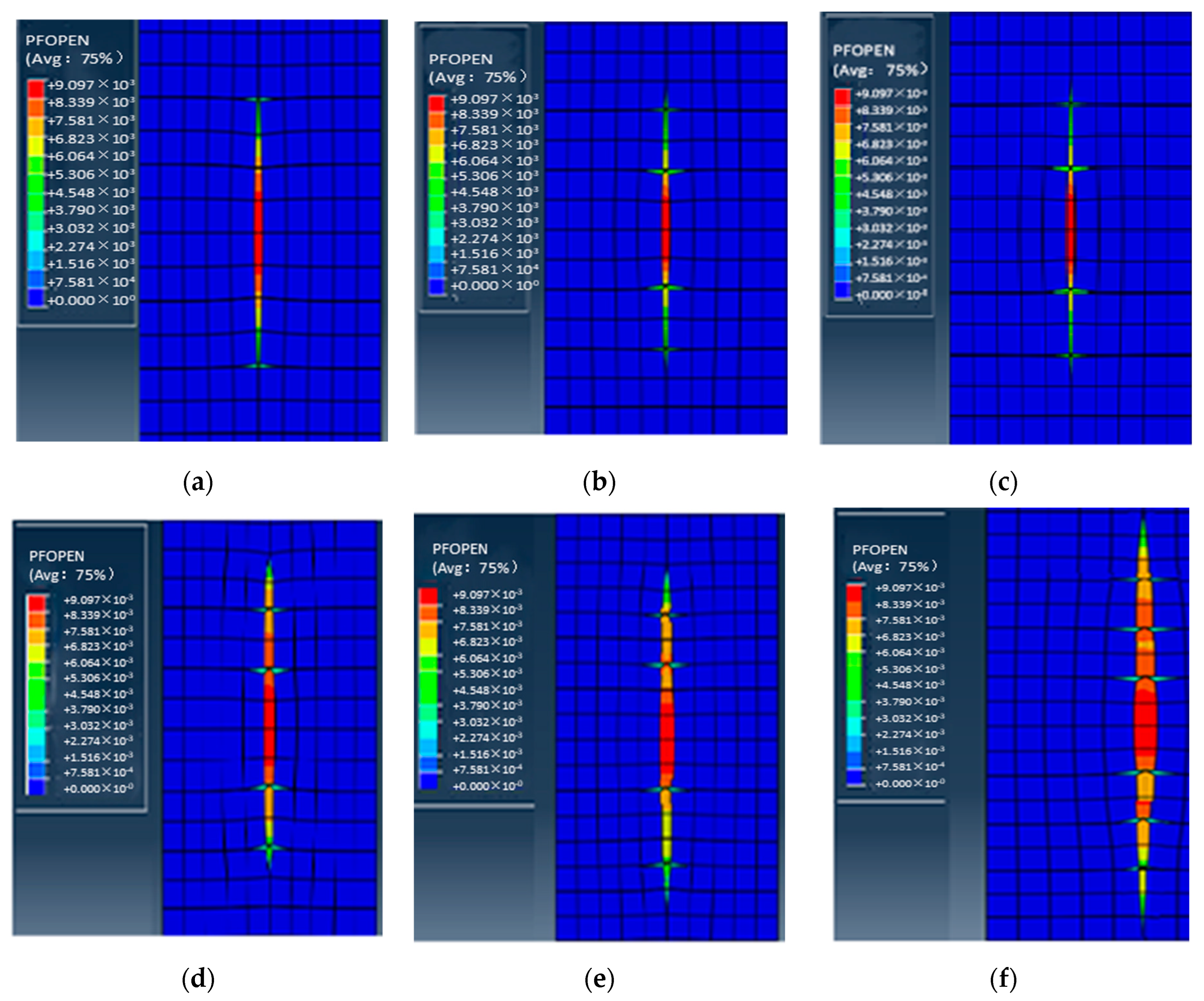
2. Numerical Simulation of Crack Height Expansion

Using the ABAQUS software (2022), a study was conducted to investigate the extension of fracture height in formations consisting of vertical limestone and shale [6,7,8]. The aim was to explore the factors that control this extension. Different combinations of shale and limestone were modeled, considering model dimensions of 20 m length, 10 m width, and 8 m height, as indicated in Table 2. Physical models were established for pure shale (Figure 2), shale mixed with limestone (Figure 3) [10,11,12,13], and the interaction between shale and limestone (Figure 4). Longxing 1, a representative well within the operational zone, was chosen for the construction of a geological model (refer to Figure 4). The model parameters were incorporated based on the interpretation data from well logging and ground stress information obtained specifically from Longxing 1 (Table 3, Table 4 and Table 5).
The model is divided into structured hex grids, i.e., structured regular hexahedral grids. The schematic diagram of the grid model is as follows (Figure 5): [14].
To ensure a more accurate representation of the scene, it is recommended to scale up the original model dimensions to 100 m in length, 60 m in width, and 30 m in height. This adjustment will effectively align with the actual geological conditions. Additionally, it is crucial to investigate the controlling factors that impact seam height while keeping consistent geological properties and construction parameters intact [15,16]. By referencing the geological characteristics observed in the Ren’an 1 well and considering how limestone layers influence shale reservoir fractures’ extension, a three-dimensional model illustrating the shale–limestone interaction within a horizontal well has been established (refer to Figure 6).

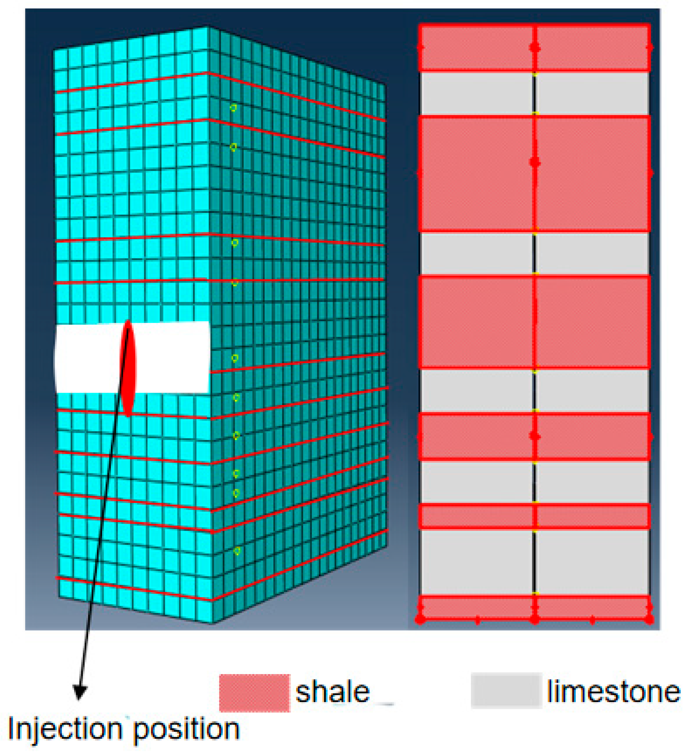
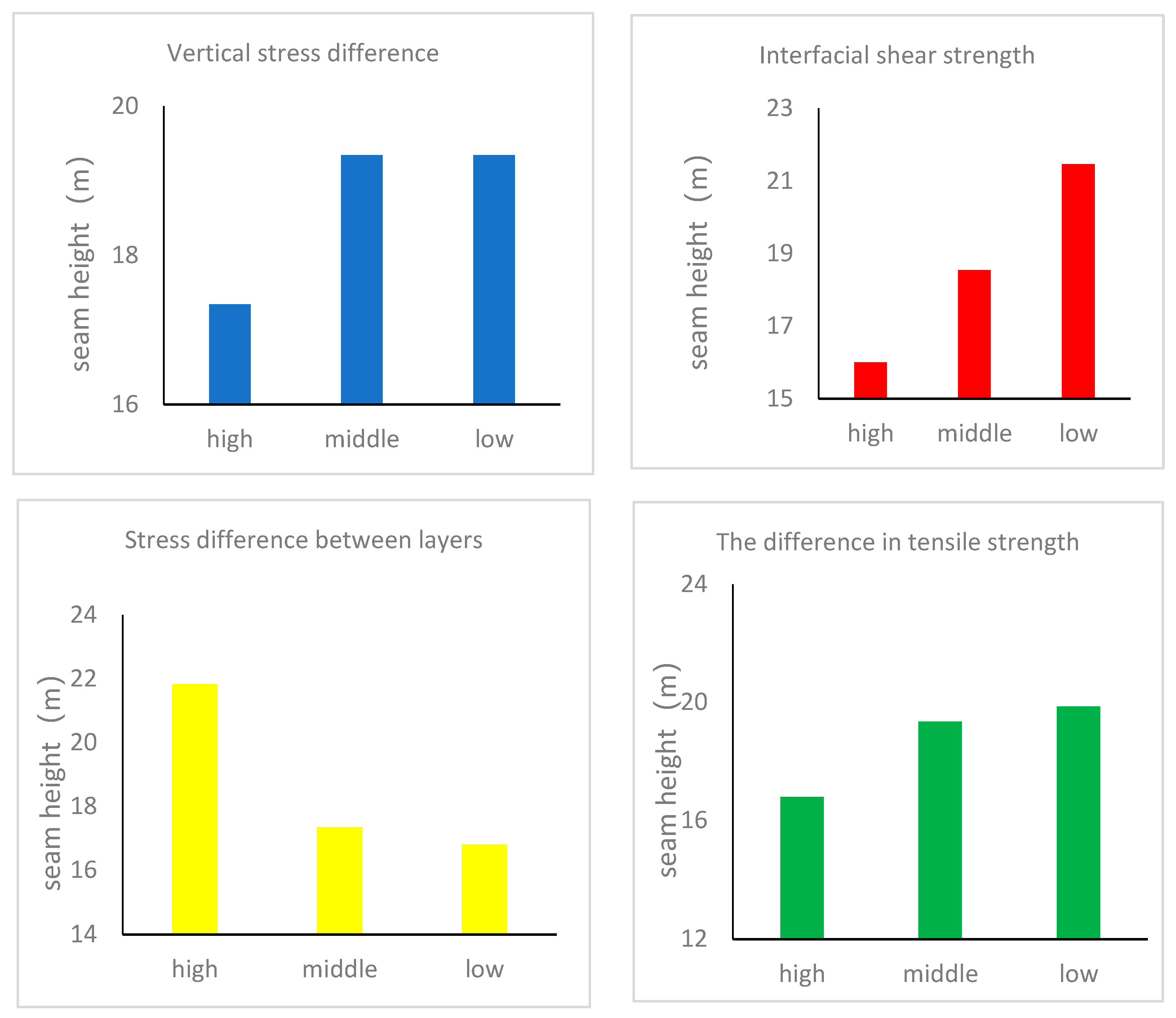
2.1. Geological Factor

2.1.1. Shear Strength of Interlayer Interface

The cementation strength of the shale interlayer interface is closely correlated with the composition and concentration of cements (such as quartz, calcite, and pyrite) and is typically quantitatively assessed through interfacial shear strength [17]. A higher cementation strength corresponds to a greater interfacial shear strength. Simulation results indicate that hydraulic fractures exhibit enhanced interlayer integrity, characterized by discontinuous fracture lengths at the interlayer while displaying limited extension within the new layer (as depicted in Figure 7). The simulation results demonstrate a clear impact of interfacial shear strength on the longitudinal propagation of hydraulic fractures. However, further simulations incorporating additional variable parameters are necessary in order to accurately quantify the extent of this influence [18]. After a prolonged period of expansion, the interlayer’s influence diminished and the fracture gradually regained its longitudinal symmetry. To further elucidate the propagation and extension morphology of hydraulic fractures under varying shear strengths, different shear strengths were employed while keeping other parameters consistent with the model. The simulation results demonstrated that variations in interlayer cementation strength significantly impacted hydraulic fracture propagation. When the interlayer shear strength was high, it facilitated enhanced penetration of hydraulic fractures into the interlayer and subsequent entry into the adjacent reservoir, thereby enabling the further expansion of the reservoir. The longitudinal propagation of hydraulic fractures remained largely unaffected, as observed in numerous large-scale model experiments conducted by scholars. This phenomenon can be attributed to the significant filtration loss experienced by fracturing fluid at low interface strength levels, resulting in substantial net pressure loss that hinders adequate support for extended hydraulic fracture growth.

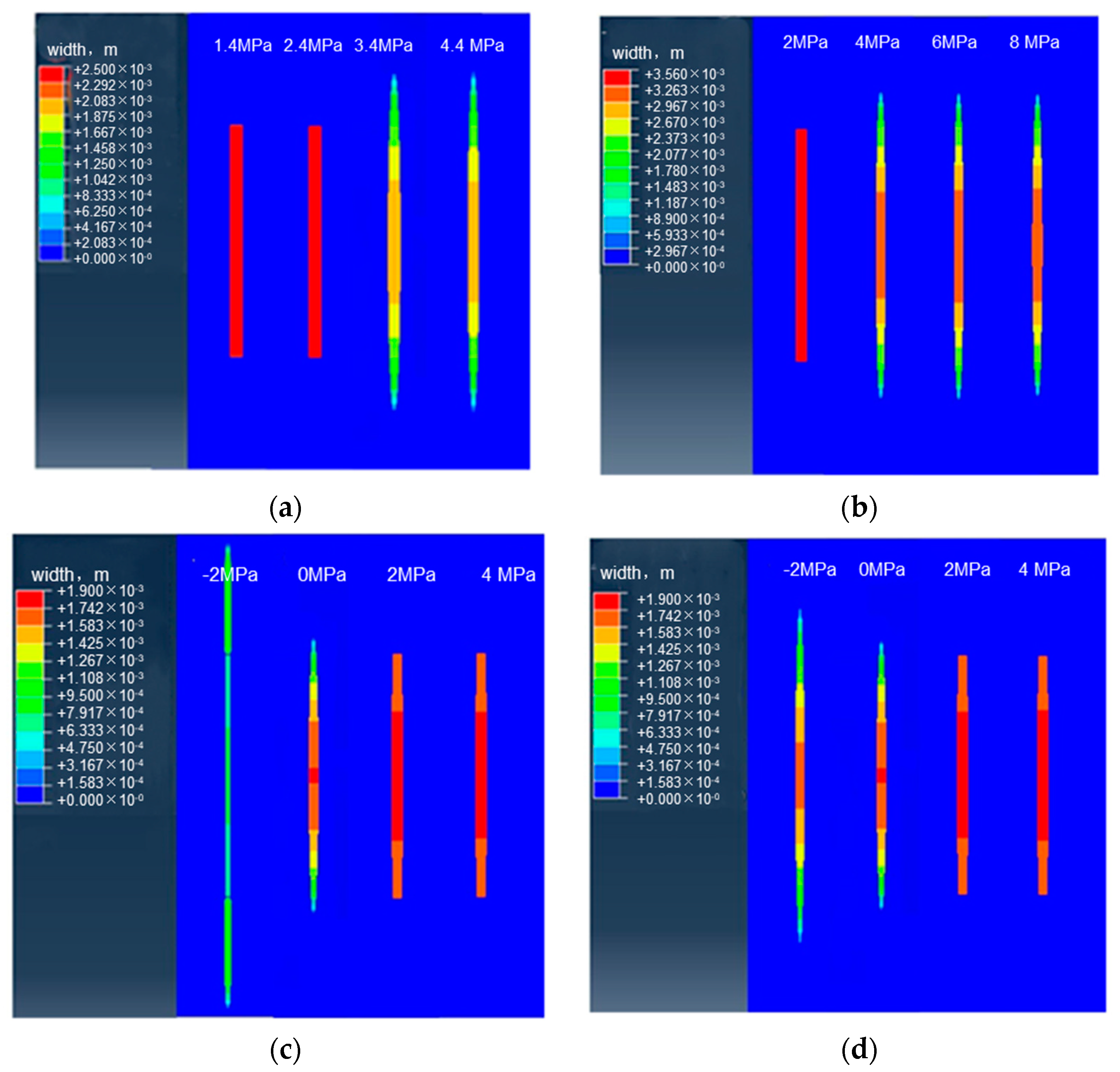
2.1.2. Vertical Stress Difference

The vertical stress difference is often referred to as the difference between the vertical geostress and the minimum horizontal geostress [19]. Different stress difference values were set to carry out the numerical simulation. The simulation results demonstrated that the high vertical stress difference was conducive to the hydraulic fracture penetrating the weak interlayer interface and entering the adjacent reservoir, so as to realize the effective longitudinal expansion of hydraulic fracture and achieve a better reconstruction effect. When the horizontal minimum principal stress was constant, the greater the vertical stress, the stronger the shear resistance of the interface, so the effect of the interface strength was reduced. Of course, when the vertical stress difference was large, it had little effect on the overall expansion morphology of the hydraulic fractures.

2.1.3. Interlayer Stress Difference

The difference in stress between the interlayers is referred to as the disparity between the minimum horizontal ground stress of the spacer and the reservoir [20,21,22]. We employed this stress discrepancy among different layers for the purpose of conducting numerical simulations. The simulation outcomes demonstrated that a lower level of stress variation between layers enhanced propagation capability, increased the fracture height, and improved the vertical propagation effectiveness of hydraulic fractures. The greater the difference in interlayer stress and the higher the net pressure required for longitudinal expansion of hydraulic fractures were, the more challenging it became for hydraulic fractures to penetrate the interface between layers into either the interlayer or the adjacent reservoir. When there was a significant disparity in interlayer stress, despite gradually increasing the net hydraulic fracture pressure, the hydraulic fractures tended to expand laterally, and their longitudinal expansion remained limited.

2.1.4. Tensile Strength Difference

The disparity between the tensile strength of the isolation layer and the reservoir is referred to as the difference in tensile strength [23]. Figure 8d presents various examples of calculations wherein the isolation layer’s tensile strengths are set at 2 MPa, 4 MPa, 6 MPa, and 8 MPa, respectively. Consequently, this results in corresponding interlayer tensile strength differences of −2 MPa, 0 MPa, 2 MPa, and 4 MPa. The simulation’s findings indicate a close alignment between hydraulic fracture penetration and interlayer stress variation caused by differences in tensile strength. During the process of hydraulic fracture propagation, it is essential for the fracture to surpass both the minimum horizontal in situ stress and the rock’s tensile strength. A smaller variation in tensile strength between layers provides an advantage in achieving successful penetration of the hydraulic fracture. Specifically, when initiating from a layer with high strength, it becomes more feasible to penetrate interfaces between layers and expand into layers with lower strength. Based on this comprehension, optimization can be achieved by considering both well penetration and perforation layers.

2.1.5. Factor Weight

Currently, the key factors impacting the extension of hydraulic fractures are interfacial shear strength, interlayer stress difference, vertical stress difference, etc. However, there is still limited clarity regarding their specific influence on the joint height of hydraulic fractures. Therefore, this study aims to quantitatively analyze the degree of influence each factor has on the joint height through extensive numerical simulations (Figure 9) and by employing the control variable method. The findings will provide valuable guidance for reservoir evaluation and the subsequent formulation of process parameters. As depicted in Figure 10, the variation in interfacial shear strength between shale and limestone exerts the most pronounced influence on the extension of hydraulic fracture height. Subsequently, the magnitude of interlayer stress difference follows suit, while the impact of vertical stress difference is comparatively weaker on hydraulic fracture height. Consequently, future models for evaluating hydraulic fracture height extension should prioritize considering interfacial shear strength. In cases where the shear strength is feeble, achieving a significant extension of hydraulic fractures becomes more challenging, thus necessitating the adoption of enhanced and aggressive process parameters to accomplish full longitudinal reconstruction objectives in reservoirs with low shear strength. Conversely, for reservoirs exhibiting robust shear strength, it is advisable to employ judicious parameters to prevent excessive expansion of the hydraulic fracture height.

2.2. Construction Displacement

Small-scale simulation: Displacement has a great influence on the vertical extension of fractures. As shown in Figure 11, the height of the fractures increased with the increase in displacement. Due to the significant displacement, the middle thin-shell limestone was always able to be pressed open, but the upper and lower far thin shell limestone were able to avoid being pressed open through displacement control. At the same time, the seam height extension in the initial injection stage was more sensitive to the flow rate. The influence of viscosity on the geometric parameters of the crack is shown in Figure 12. With the increase in the viscosity of the fracturing fluid, the fracture height was larger, and the fracture height extension at different fracture lengths was more uniform. A small-scale numerical simulation demonstrated the significant impact of construction displacement and liquid viscosity on the height expansion of hydraulic fractures. The influence of construction displacement surpassed that of liquid viscosity in the early stage, while the effect of liquid viscosity became more pronounced during the middle and late stages. To further apply these findings to mining operations, a large-scale numerical simulation was conducted [24,25].
Large-scale simulation: The impact of displacement on the extension of seam height is illustrated in Figure 13. The increase in displacement led to a corresponding rise in seam height, attributed to the larger magnitude of displacement. As the displacement progressively escalated, cracks consistently propagated along the vulnerable interfaces between layers, resulting in an elevation of crack height [26,27,28]. Specifically, when the displacement escalated from 8 m3/min to 16 m3/min, there was a breakthrough at the layer interface, and subsequently, a 25% augmentation in crack height occurred.

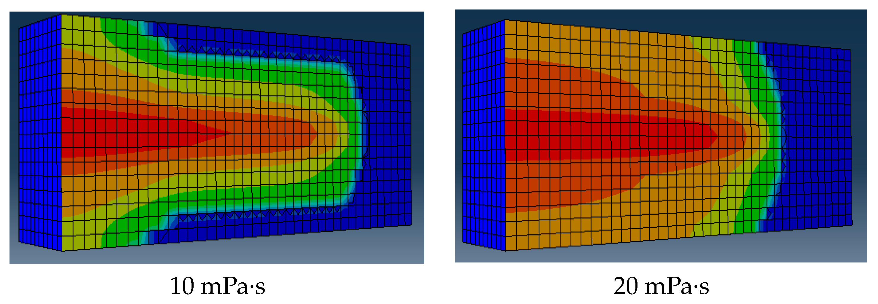
2.3. The Viscosity of Fracturing Fluid

The influence of viscosity on crack height elongation is illustrated in Figure 14. It can be observed that with an increase in viscosity, there was a corresponding increase in crack height; however, the magnitude of this increase was relatively small. Specifically, when the viscosity reached 20 mPa·s, the seam height experienced a 6% change. Moreover, as the viscosity surpassed 50 mPa·s, the ability to penetrate through layer interfaces was significantly enhanced, consequently leading to a substantial elevation in seam height.
The simulation results demonstrate that the fracture height extension of the limestone and shale layers is significantly influenced by reservoir stress. To achieve effective perforation fracturing, it is recommended to employ high-displacement (>14 m3/min) and high-viscosity liquid (>100 mPa·s). On-site construction can involve the pre-application of high-viscosity liquid and the utilization of high-displacement techniques to ensure adequate reservoir transformation.

2.4. Simulation of Temporary Blocking and Turning to Fracturing in Horizontal Wells

2.4.1. Simulation of Temporarily Blocked Clusters

Using the identical stress uniform hole layout, a construction displacement of 16.0 m3/min, and an injection volume of 1400 m3, we aimed to simulate the crack morphology under three scenarios: no temporary blocking, temporary blocking with three clusters, and temporary blocking with four clusters in a single section. It is evident that in the absence of temporary blocking, cracks predominantly extended on both sides, while their extension in the middle was significantly suppressed. When the number of temporarily blocked clusters reached three, the crack length in each cluster became relatively uniform. Furthermore, as the number of temporarily blocked clusters increased to four, there was a further enhancement in the uniformity of the crack extension within each cluster (Figure 15).
Using an identical stress layout with uniform holes, a construction displacement of 16.0 m3/min, and an injection volume of 1800 m3, we simulated the crack morphology under three scenarios: no temporary blocking, temporary blocking with four clusters, and temporary blocking with six clusters in a single section. It is evident that when not temporarily blocked, the stress shadows suppressed the extension of four crack clusters almost entirely. However, when there were four temporarily blocked clusters, all except for the fifth cluster exhibited improved crack extension lengths. When the number of clusters that were temporarily blocked reached six, there was a consistent level of crack extension observed in each cluster (Figure 16) [29,30].

2.4.2. Stress Difference Simulation

Using a construction displacement rate of 16.0 m3/min and an injection volume of 1800 m3, the simulation was conducted to analyze the crack propagation morphology under stress differences of 0 MPa, 2 MPa, and 4 MPa in a single segment consisting of seven clusters (Figure 17). It is evident that, at a stress difference of 0 MPa, there existed a significant variation in the lengths of each cluster’s cracks. However, as the stress difference increased from 2 MPa to 4 MPa, the disparity in crack length among the individual clusters diminished. The analysis suggested that employing a stress mode characterized by low-to-medium stress, with sequential increments on both sides, could partially mitigate the impact of stress shadows between cracks while enhancing the uniformity of crack extension within each cluster. Consequently, for subsequent designs, it is recommended that a combination strategy involving non-uniform distribution of fractures be adopted, along with temporary plugging between fractures to achieve effective transformation of the reservoir sections [31,32].

3. Results

Based on our understanding of the longitudinal expansion of fractures, we conducted a field operation in which we selected the Qiulin 22 well, a representative well within the work area, for testing purposes.
The Qiulin 22 well is a development well located in the Daanzhai shale oil reservoir, characterized by a lithology comprising interbedded layers of shale and limestone. However, this particular well encounters challenges in terms of fully exploiting the reservoir’s lengthwise potential due to the presence of limestone and lithologic interfaces. These factors significantly impede the effective extension of hydraulic fractures, thereby hindering successful reservoir reconstruction (Figure 18).
The well was modified by utilizing pre-grouting fluid (120 mPa·s), slick water, and a high displacement rate (16 m3/min). The microseismic monitoring results demonstrated successful fracture penetration into the layer, the reservoir position of this well being 3056.0–3087.0, with a vertical depth of 2875~2888 m. Microseismic monitoring indicated that the hydraulic fracture had a top seam height of 2869 m and a bottom seam height of 2892 m, confirming the complete reformation of the reservoir and validating the effectiveness of the process. This successful operation on the Qiulin 22 well serves as evidence for the efficacy of this study (Figure 19).
The technique of temporary joint plugging was utilized in the Long’an 1 well. The Long’an 1 well is a horizontal well in Da’anzhai Formation. The reservoir in this well contains interacting shale and limestone. The stress difference between sections is significant; the stress heterogeneity is extremely strong; and the uniform expansion of hydraulic fractures is difficult, so it is difficult to achieve full reservoir reconstruction, and the reconstruction effect is limited. In this well, 50 perforations were made in the seventh section and 20 balls were temporarily plugged based on research findings. Prior to the temporary plugging, event points responded on both sides of the well, with a non-perpendicular azimuth angle of fracture extension on the east side. However, after temporary plugging, the event points showed outward extension tendencies perpendicular to the well on both sides, indicating the significant effectiveness of this approach. Figure 15 illustrates this effect, with blue and red dots representing pre- and post-plugging event points, respectively. Therefore, it is imperative to employ temporary plugging technology for such reservoirs in order to enhance the uniform expansion degrees of hydraulic fractures and to achieve optimal reservoir reconstruction outcomes (Figure 20).

4. Discussion

(1)
By employing finite element numerical simulation, this investigation has unveiled the primary factors influencing the longitudinal propagation of interactive lithology, specifically interlayer interface strength and interlayer stress disparity. These findings possess significant implications for comprehending hydraulic fracture propagation in intricate lithological formations.
(2)
Currently, the exploration and development of continental shale oil is experiencing a significant surge, but it will encounter numerous challenges in terms of reconstructing intricate lithologic reservoir layers. Therefore, this study holds substantial practical significance.
(3)
The propagation of longitudinal fractures in shale oil reservoirs containing interbedded shale and limestone formations is highly intricate. The author strongly advocates for further comprehensive research, combined with large-scale model experiments, to delve more deeply into this complex phenomenon.
(4)
This study aims to optimize the parameters for temporary plugging through numerical simulation. However, it is important to note that the temporary plugging process requires a more systematic investigation. Further research on the temporary plugging machine and evaluation of its effectiveness are necessary.

5. Conclusions

(1)
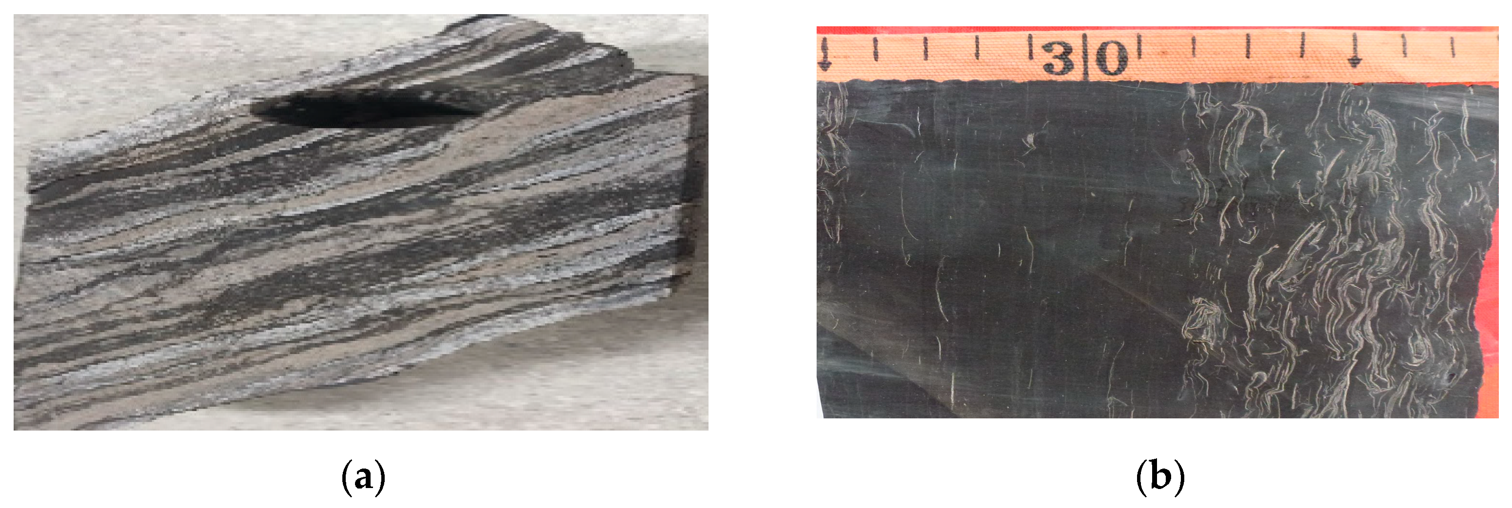
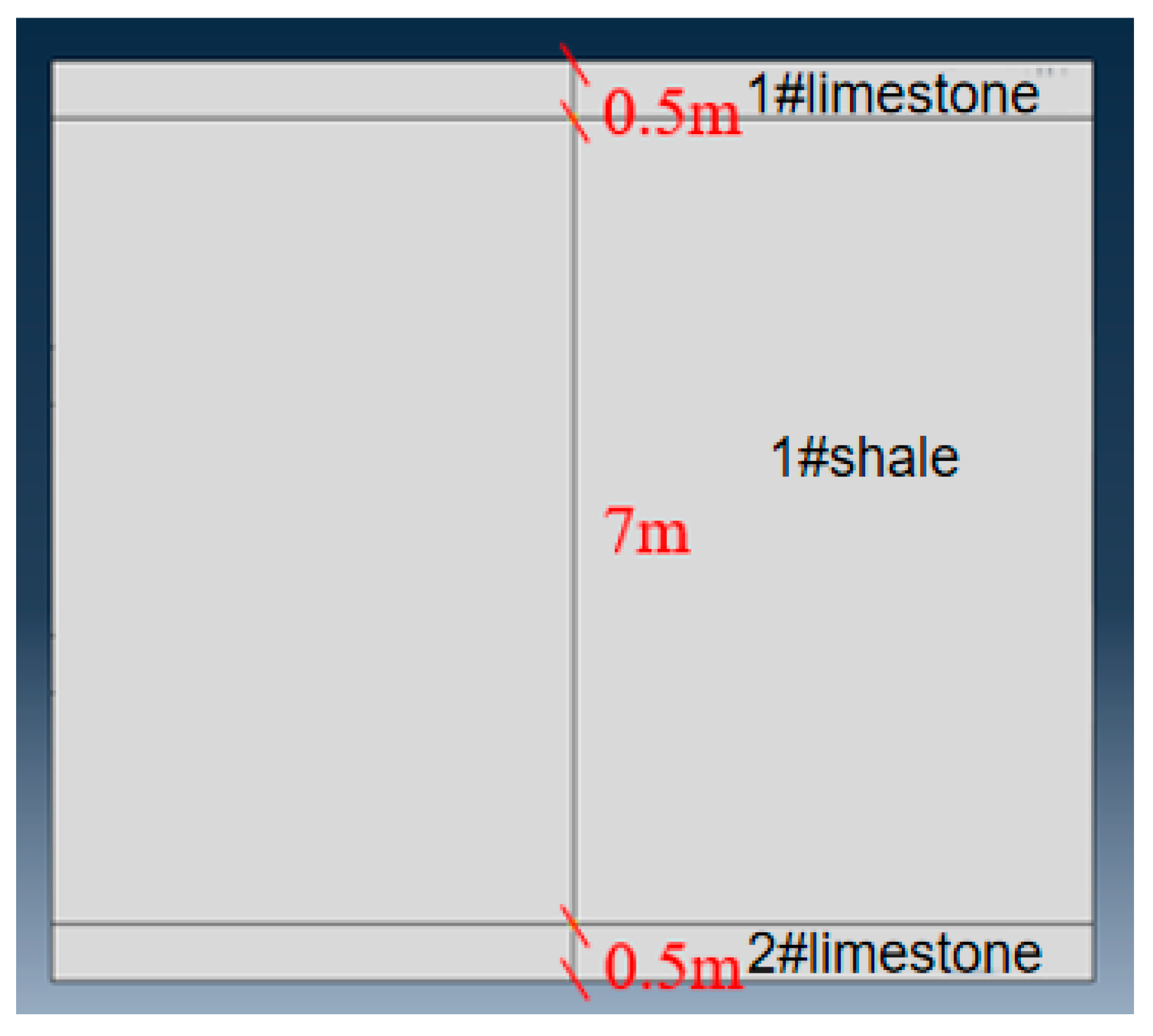
The reservoir consisted of shale and limestone, with the Young’s modulus and stress of the limestone layer being notably higher than those of the shale layer. In the initial stage, a slack-water volume fracturing process was employed, resulting in significant inhibition of the fracture height.
(2)
Finite element numerical simulation revealed that the longitudinal propagation of hydraulic fractures is influenced by interlayer interface strength, interlayer stress differential, fracturing displacement, and viscosity.
(3)
The results of the numerical simulation demonstrated the indispensability of employing a combination of substantial displacement and pre-viscous liquid in order to accomplish longitudinal penetration.
(4)
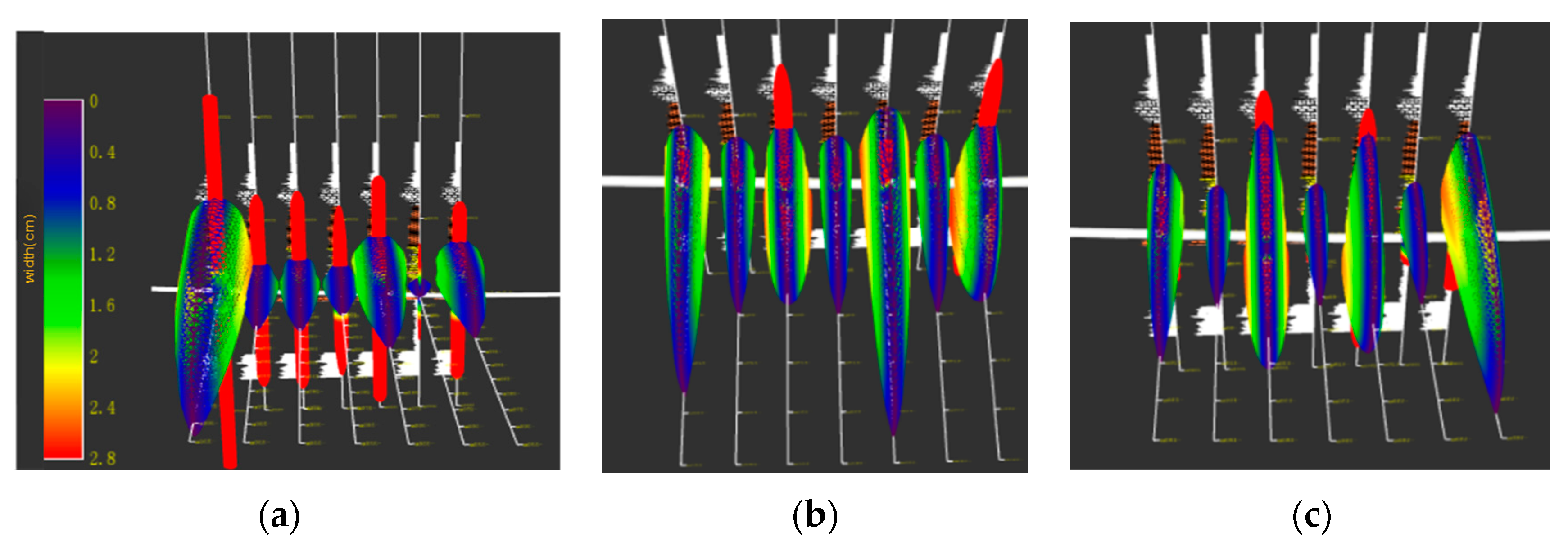
Horizontal wells exhibit significant heterogeneity, posing challenges in terms of achieving uniform hydraulic fracture propagation. Through the implementation of a temporary plugging process, approximately 40% of the perforations were effectively obstructed, facilitating the even expansion of multiple fracture clusters.
(5)
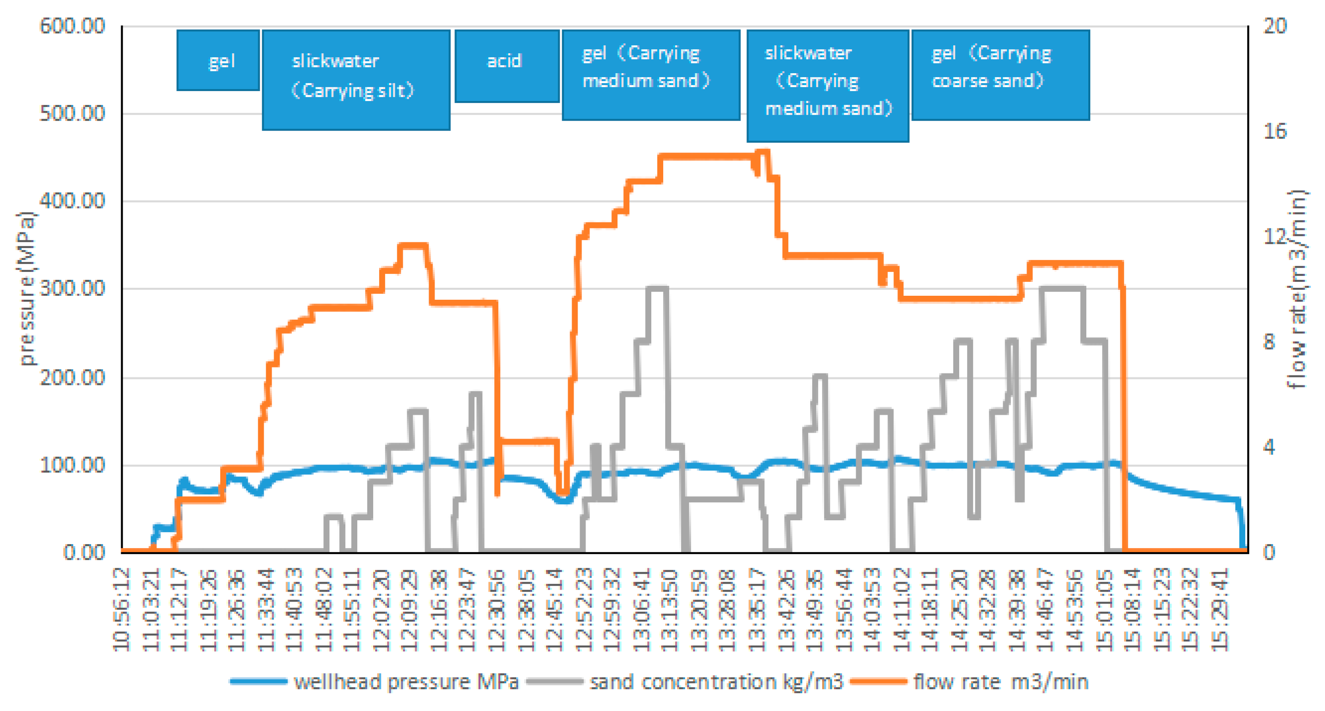
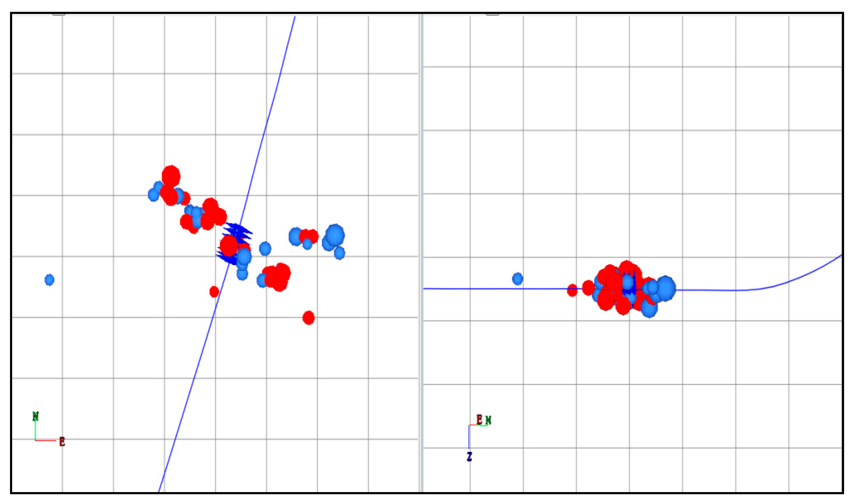
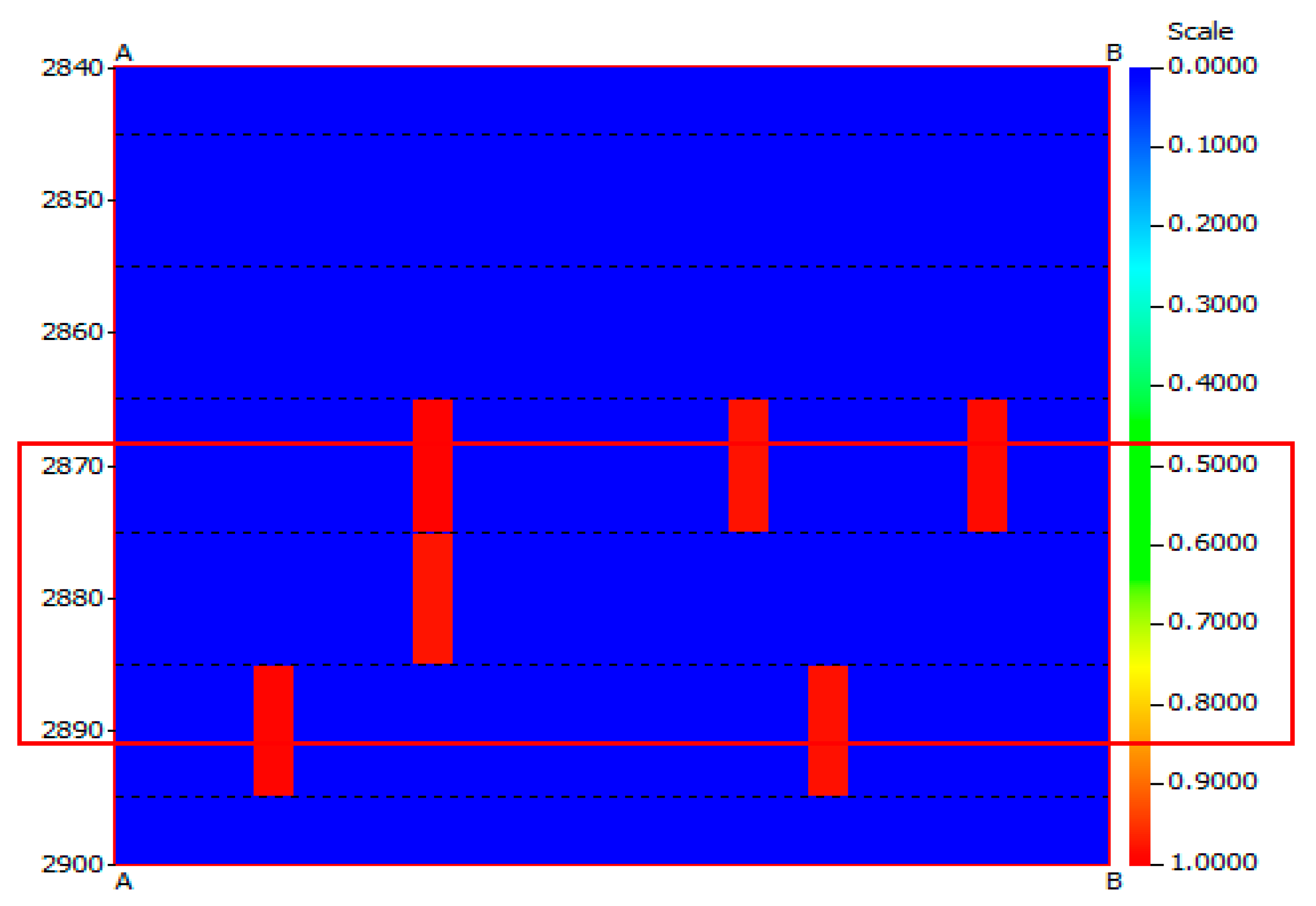
The application results demonstrated the successful implementation of the perforating fracturing process in the Qiulin 22 well. The monitoring results confirmed the effectiveness of this recommended procedure, thereby validating its reliability.

Author Contributions

Z.L. is responsible for the overall idea and design of the article; W.C. and F.L.: supported the on-site application of technology; S.L.: supported relevant technical research; Y.W.: conducted geological mechanics experiments and analysis; R.H.: set model parameters and optimized parameters. All authors have read and agreed to the published version of the manuscript.

Funding

This research received no external funding.

Data Availability Statement

Data available on request due to restrictions eg privacy or ethical. The data presented in this study are available on request from the corresponding author. The data are not publicly available due to the privacy.

Conflicts of Interest

The authors declare no conflict of interest.

References

  1. Zou, Y.; Zhang, S.; Ma, X.; Zhang, X.; Zhang, S. Hydraulic fracture morphology and conductivity of continental shale under the true-triaxial stress conditions. Fuel 2023, 352, 129056. [Google Scholar] [CrossRef]
  2. Tan, P.; Jin, Y.; Hou, B.; Yuan, L.; Xiong, Z. Experimental investigation of hydraulic fracturing for multi-type unconventional gas co-exploitation in Ordos basin. Arab. J. Sci. Eng. 2019, 44, 10503–10511. [Google Scholar] [CrossRef]
  3. Hou, B.; Wu, A.; Chang, Z.; You, Y.; Kou, X.; Zhang, F. Experimental study on vertical propagation of fractures of multi-sweet of spots shale oil reservoir. Chin. J. Geotech. Eng. 2021, 43, 1322–1330. [Google Scholar]
  4. Wang, Y.; Hou, B.; Wang, D.; Jia, Z. Features of fracture height propagation in cross-layer fracturing of shale oil reservoirs. Pet. Explor. Dev. 2021, 48, 469–479. [Google Scholar] [CrossRef]
  5. Zhao, J.; Li, Y.; Wang, S.; Jiang, Y.; Zhang, L. Simulation of complex fracture networks influenced by natural fractures in shale gas reservoir. Nat. Gas Ind. B 2014, 1, 89–95. [Google Scholar]
  6. Guo, J.; Luo, B.; Lu, C.; Lai, J.; Ren, J. Numerical investigation of hydraulic fracture propagation in a layered reservoir using the cohesive zone method. Eng. Fract. Mech. 2017, 186, 195–207. [Google Scholar] [CrossRef]
  7. Huang, L.; Liu, J.; Zhang, F.; Dontsov, E.; Damjanac, B. Exploring the influence of rock inherent heterogeneity and grain size on hydraulic fracturing using discrete element modeling. Int. J. Solids Struct. 2019, 176, 207–220. [Google Scholar] [CrossRef]
  8. Zhu, Z.Q.; Sheng, Q.; Fu, X.D. Numerical simulation of fracture propagation of heterogeneous material. Appl. Mech. Mater. 2012, 170, 581–584. [Google Scholar] [CrossRef]
  9. Paluszny, A.; Zimmerman, R.W. Numerical simulation of multiple 3D fracture propagation using arbitrary meshes. Comput. Methods Appl. Mech. Eng. 2011, 200, 953–966. [Google Scholar] [CrossRef]
  10. Wang, Y.; Lv, Z. Composite stimulation technology for improving fracture length and conductivity of unconventional reservoirs. Front. Phys. 2023, 11, 1181302. [Google Scholar] [CrossRef]
  11. Li, J.; Dong, S.; Hua, W.; Li, X.; Pan, X. Numerical investigation of hydraulic fracture propagation based on cohesive zone model in naturally fractured formations. Processes 2019, 7, 28. [Google Scholar] [CrossRef]
  12. Shi, X.; Qin, Y.; Xu, H.; Xu, H.; Feng, Q.; Wang, S.; Xu, P.; Han, S. Numerical simulation of hydraulic fracture propagation in conglomerate reservoirs. Eng. Fract. Mech. 2021, 248, 107738. [Google Scholar] [CrossRef]
  13. Shou, Y.; Zhou, X.; Berto, F. 3D numerical simulation of initiation, propagation and coalescence of cracks using the extended non-ordinary state-based peridynamics. Theor. Appl. Fract. Mech. 2019, 101, 254–268. [Google Scholar] [CrossRef]
  14. Fei, Y. Rock fracture toughness during hydraulic fracture extension. J. Rock Mech. Eng. 2004, 14, 2346–2350. [Google Scholar]
  15. Jiang, T. Research and application prospect of fracture complexity index for shale oil and gas horizontal wells. Pet. Drill. Technol. 2013, 2, 7–12. [Google Scholar]
  16. Chen, M.; Pang, F.; Jin, Y. Simulation and analysis of large-scale true triaxial hydraulic fracturing. J. Rock Mech. Eng. 2000, z1, 868–872. [Google Scholar]
  17. Hou, Z.; Cheng, H.; Sun, S.; Chen, J.; Qi, D.; Liu, Z. Study on hydraulic fracturing and fracture propagation law in rocks with different lithology. Appl. Geophys. 2019, 2, 243–251+255. [Google Scholar] [CrossRef]
  18. Zhou, T.; Wang, H.; Li, F.; Li, Y.; Zou, Y.; Zhang, C. Numerical simulation of hydraulic fracture propagation in laminated shale reservoirs. Pet. Explor. Dev. 2020, 47, 1117–1130. [Google Scholar] [CrossRef]
  19. Yang, W.; Geng, Y.; Zhou, Z.; Li, L.P.; Gao, C.L.; Wang, M.X.; Zhang, D.S. DEM numerical simulation study on fracture propagation of synchronous fracturing in a double fracture rock mass. Geomech. Geophys. Geo-Energy Geo-Resour. 2020, 6, 39. [Google Scholar] [CrossRef]
  20. Taleghani, A.D.; Gonzalez-Chavez, M.; Yu, H.; Asala, H. Numerical simulation of hydraulic fracture propagation in naturally fractured formations using the cohesive zone model. J. Pet. Sci. Eng. 2018, 165, 42–57. [Google Scholar] [CrossRef]
  21. Wang, S.; Li, H.; Li, D. Numerical simulation of hydraulic fracture propagation in coal seams with discontinuous natural fracture networks. Processes 2018, 6, 113. [Google Scholar] [CrossRef]
  22. Zhang, B.; Ji, B.; Liu, W. The study on mechanics of hydraulic fracture propagation direction in shale and numerical simulation. Geomech. Geophys. Geo-Energy Geo-Resour. 2018, 4, 119–127. [Google Scholar] [CrossRef]
  23. Liu, W.; Zeng, Q.; Yao, J. Numerical simulation of elasto-plastic hydraulic fracture propagation in deep reservoir coupled with temperature field. J. Pet. Sci. Eng. 2018, 171, 115–126. [Google Scholar] [CrossRef]
  24. Sun, C.; Zheng, H.; Liu, W.D.; Lu, W. Numerical simulation analysis of vertical propagation of hydraulic fracture in bedding plane. Eng. Fract. Mech. 2020, 232, 107056. [Google Scholar] [CrossRef]
  25. Bakhshi, E.; Golsanami, N.; Chen, L. Numerical modeling and lattice method for characterizing hydraulic fracture propagation: A review of the numerical, experimental, and field studies. Arch. Comput. Methods Eng. 2021, 28, 3329–3360. [Google Scholar] [CrossRef]
  26. Hossain, M.M.; Rahman, M.K. Numerical simulation of complex fracture growth during tight reservoir stimulation by hydraulic fracturing. J. Pet. Sci. Eng. 2008, 60, 86–104. [Google Scholar] [CrossRef]
  27. Zeng, Q.; Yao, J. Numerical simulation of fracture network generation in naturally fractured reservoirs. J. Nat. Gas Sci. Eng. 2016, 30, 430–443. [Google Scholar] [CrossRef]
  28. Sanchez, E.C.M.; Cordero, J.A.R.; Roehl, D. Numerical simulation of three-dimensional fracture interaction. Comput. Geotech. 2020, 122, 103528. [Google Scholar] [CrossRef]
  29. Wen, M.; Huang, H.; Hou, Z.; Wang, F.; Qiu, H.; Ma, N.; Zhou, S. Numerical simulation of the non-Newtonian fracturing fluid influences on the fracture propagation. Energy Sci. Eng. 2022, 10, 404–413. [Google Scholar] [CrossRef]
  30. Guo, T.; Qu, Z.; Gong, F.; Wang, X. Numerical simulation of hydraulic fracture propagation guided by single radial boreholes. Energies 2017, 10, 1680. [Google Scholar] [CrossRef]
  31. Ju, Y.; Wang, Y.; Xu, B.; Chen, J.; Yang, Y. Numerical analysis of the effects of bedded interfaces on hydraulic fracture propagation in tight multilayered reservoirs considering hydro-mechanical coupling. J. Pet. Sci. Eng. 2019, 178, 356–375. [Google Scholar] [CrossRef]
  32. Cheng, Y.; Zhang, Y.; Yu, Z.; Hu, Z.; Yang, Y. An investigation on hydraulic fracturing characteristics in granite geothermal reservoir. Eng. Fract. Mech. 2020, 237, 107252. [Google Scholar] [CrossRef]
Figure 1. (a) Gong 119H Da’anzhai Reservoir (2593.6–2593.8m); (b) Longxing 1 Well Da’anzhai Section Core (3641 m, shale; 3636 m, shell limestone).
Processes 11 03190 g001
Figure 2. Schematic diagram of a pure shale model.
Processes 11 03190 g002
Figure 3. Schematic diagram of a shale mixed with limestone model.
Processes 11 03190 g003
Figure 4. Schematic diagram of a shale–limestone interaction model.
Processes 11 03190 g004
Figure 5. Model schematic diagram.
Processes 11 03190 g005
Figure 6. Schematic diagram of shale–limestone interaction model.
Processes 11 03190 g006
Figure 7. Simulation of hydraulic crack propagation at a strong level of shear strength.
Processes 11 03190 g007
Figure 8. The results of the numerical simulation. (a) Interlayer interface strength; (b) vertical stress difference; (c) stress difference between layers; (d) the difference in tensile strength.
Processes 11 03190 g008
Figure 9. Simulated scheme.
Processes 11 03190 g009
Figure 10. Analysis of orthogonal test results.
Processes 11 03190 g010
Figure 11. Different displacement joint height extension simulation at the initial injection stage.
Processes 11 03190 g011
Figure 12. Simulation of seam height extension of liquids of different viscosities.
Processes 11 03190 g012
Figure 13. Extension of seam height with different displacements: (a) 8 m3/min; (b) 10 m3/min; (c) 12 m3/min; (d) 14 m3/min.
Processes 11 03190 g013
Figure 14. Elongation of crack height for liquids of different viscosities: (a) 1 mPa·s; (b) 10 mPa·s; (c) 20 mPa·s; (d) 50 mPa·s; (e) 100 mPa·s; (f) 200 mPa·s.
Processes 11 03190 g014
Figure 15. Simulation of crack morphology with different numbers of clusters temporarily blocked (7 clusters within the segment). (a) Not temporarily blocked; (b) temporarily blocking 3 clusters; (c) temporarily blocking 4 clusters.
Processes 11 03190 g015
Figure 16. Simulation of crack morphology with different numbers of clusters temporarily blocked (10 clusters within the segment). (a) Not temporarily blocked; (b) temporarily blocking 3 clusters; (c) temporarily blocking 4 clusters.
Processes 11 03190 g016
Figure 17. Simulation of crack morphology with varying stress differences between clusters (7 clusters within the segment). (a) 0 MPa; (b) 2 MPa; (c) 4 MPa.
Processes 11 03190 g017
Figure 18. Pumping procedure for the construction of well QL22.
Processes 11 03190 g018
Figure 19. Microseismic monitoring results for well QL22.
Processes 11 03190 g019
Figure 20. Application effect of temporary plugging technology in the Longan 1 well. (The red event point indicates after the temporary block, and the blue event point indicates before the temporary block).
Processes 11 03190 g020
Table 1. Stress characteristics of Da’anzhai shale oil reservoir.
WellLithologyMaximum Horizontal Principal Stress
MPa
Minimum Horizontal Principal Stress
MPa
Vertical Stress
MPa
Coefficient of Stress Difference
Nanchong
2H
Shale74.762.2364.220.2
Longan1Shale81.671.9889.050.13
limestone94.281.589.60.16
Renan1Shale51.7443.762.70.18
limestone67.0556.262.80.19
Table 2. Rock mechanical characteristics of Daanzhai shale oil reservoir.
WellLithologyDepth
m
Compressive Strength
MPa
Young’s Modulus
104 MPa
Poisson’s Ratio
Longan1limestone3485.72~3485.95325.14.740.28
Shale3505.58~3505.68214.82.250.23
limestone3508.17~3508.33187.42.920.2
3514.27~3514.45210.14.290.31
Renan1Shale2453.13~2453.44130.842.2360.182
Shale2456.69~2456.90140.032.0050.234
141.882.1370.329
Shale2459.72~2459.84169.152.40.208
limestone2465.12~2465.26281.794.2570.256
274.053.6790.26
limestone2474.43~2474.59184.993.5560.333
196.854.0910.288
Table 3. Mechanical parameters of the rock in well Longxing 1.
Depth
m
LithologyCompressive Strength
MPa
Young’s Modulus
104 MPa
Poisson’s Ratio
3639.00~3639.18Limestone399.526.3180.364
Shale404.965.0920.277
3673.95~3674.15Shale208.972.2330.11
Shale interbedded with limestone291.033.4440.21
Limestone212.82.5740.195
Limestone and shale interbedded266.524.2940.294
210.92.7020.271
Table 4. Logging interpretation data of well Longxing 1.
Serial NumberTop Depth
m
Bottom Depth
m
Thickness
m
TOC
%
Total Gas Content
m3/t
POR
%
SW
%
PERM
mD
136273652.425.41.41.56.462.10.34
23652.43666.4141.41.34.558.40.122
33666.43690.524.11.31.24.869.80.138
Table 5. Reference table for values of strata and construction parameters.
Shale Porosity, %5.5Porosity of Shell Limestone Layer, %1.9
Shale permeability, nD90Permeability of shell limestone layer, mD0.01
Young’s modulus of shale formation, GPa24Young’s modulus of shell limestone, GPa38
Poisson’s ratio of shale beds, dimensionless0.26Poisson’s ratio of shell limestone, dimensionless0.31
Injection rate, m3/min8.0~14.0Working fluid viscosity, mPa·s1~20
Disclaimer/Publisher’s Note: The statements, opinions and data contained in all publications are solely those of the individual author(s) and contributor(s) and not of MDPI and/or the editor(s). MDPI and/or the editor(s) disclaim responsibility for any injury to people or property resulting from any ideas, methods, instructions or products referred to in the content.

