Article

Enhanced Performance of Micro Deep Drawing through the Application of TiO2 Nanolubricant and Graphene Lubricants on SUS 301 Stainless Steel Foil

1
School of Mechanical, Materials, Mechatronic and Biomedical Engineering, Wollongong, NSW 2522, Australia
2
Welding Engineering and Laser Processing Centre, Cranfield University, Bedfordshire MK43 0AL, UK
3
College of Mechanical and Electrical Engineering, Central South University, Changsha 410083, China
4
School of Intelligent Manufacturing and Control Engineering, Shanghai Polytechnic University, Shanghai 201209, China
5
Graduate School of System Design, Tokyo Metropolitan University, Hino, Tokyo 191-0055, Japan
*
Author to whom correspondence should be addressed.
Processes 2023, 11(10), 3042; https://doi.org/10.3390/pr11103042
Submission received: 2 September 2023 / Revised: 17 October 2023 / Accepted: 20 October 2023 / Published: 23 October 2023
(This article belongs to the Special Issue Processing, Manufacturing and Properties of Metal and Alloys)

Abstract

:
In recent years, the quest for effective lubrication in micro deep drawing (MDD) has seen promising advancements. In this study, the influence of TiO2 nanolubricants and graphene lubricants on the performance of 301 stainless steel foil in MDD is examined. The MDD undergoes an extensive evaluation of various lubrication conditions, including dry, TiO2 nanolubricant, graphene lubricant at concentrations of 2.5 mg/mL, 5.0 mg/mL, and 10.0 mg/mL, as well as combined applications of TiO2 and graphene lubricants. Utilising a 5.0 mg/mL graphene lubricant together with TiO2 nanolubricants led to a significant reduction in drawing force, highlighting the synergistic efficacy of this combined lubricant. A pronounced enhancement in the consistency of the produced microcups was also attained. These results emphasise the promise of TiO2 nanolubricant and graphene lubricants in optimising the MDD process.

1. Introduction

Micro deep drawing (MDD) has emerged as a crucial process in the manufacturing landscape, courtesy of the growing demands of industries such as medical, aerospace, and electronics. This technique, which transforms flat metal foils into intricately formed cup-like structures at a microscopic level, is noted for its precision and repeatability [1,2]. Despite its remarkable potential, MDD has challenges, there remain significant challenges to overcome, including understanding the effects of size on material properties, accounting for higher drawing velocities, and optimising lubrication conditions. A key challenge arising from MDD is the high friction at the tool-workpiece interface. This can accelerate tool wear, compromise forming, and reduce surface quality of the product [3]. Table 1 contrasts findings from previous studies, highlighting various lubricant to enhance product quality and counter friction. One common mitigation strategy involves the use of lubricants, which reduce friction and enhance the efficiency of the MDD [4,5].
Conventional lubricants fall short in MDD as they readily displace at micro scales [11,12]. This motivates exploring innovative friction-reducing technologies. Nanolubricants, enriched with nanometric additives, are one such recent advancement [13,14]. Chang et al. [15] investigated TiO2 NP-infused nanolubricants for piston-cylinder interfaces. Their findings revealed these nanoparticles (NPs) led to reduced friction and wear rates, enhancing the overall lubricant performance. Glycerol, widely recognised for its high solubility and compatibility with various materials, including metal surfaces, is often employed as a dispersant in nanolubricants [16,17]. A glycerol-based nanolubricant with TiO2 NPs may offer optimal stability and lubrication for MDD applications. However, Wu et al. [18,19] examined TiO2 nano-additives in lubricants. They highlighted an agglomeration challenge that could impede lubricant performance. Azman et al. [20] explored the benefits of graphene nanosheets (GNS) coatings in addressing the agglomeration in TiO2 nanolubricants. They found that the inclusion of GNS reduced friction and wear by 5 and 15% respectively, underlining potential of graphene as an effective anti-agglomeration strategy. These GNS layers, owing to their unique structural and physical properties, can prevent the agglomeration of TiO2 NPs, thereby enhancing their effectiveness in the nanolubricant [21,22,23]. Besides, The honeycomb structure of single-layer carbon atoms in graphene imparts superb lubricating properties [24,25]. Kim et al. [26] used Chemical Vapor Deposition (CVD) to produce graphene films on Cu and Ni catalysts, which were then transferred onto SiO2/Si substrates. These films displayed excellent adhesion and friction reduction, even in multilayers a few nanometers thick. Through Scanning Tunneling Microscopy (STM), Feng et al. [27] revealed the sliding mechanism on graphene involving a commensurate-incommensurate transition. Cho et al. [28] investigated how surface morphology affects friction on different substrates. They discovered that flat graphene results in greater friction reduction compared to bulk-like graphene. Thicker graphene films increase friction on rough surfaces owing to “puckering effect”, emphasising graphene thickness as a critical factor influencing lubrication.
In this study, the impact of various lubrication conditions on MDD is examined, including unlubricated, 2.0 wt% TiO2 nanolubricant, graphene lubricants at 2.5 mg/mL, 5 mg/mL, and 10 mg/mL concentrations, as well as combinations of TiO2 nanolubricant with each graphene lubricant, respectively. The primary aim is to unravel the performance attributes of these lubricants when applied in MDD, while also evaluating the profile of drawn microcups under specific lubrication circumstances. Findings reveal that the combined use of TiO2 and 5 mg/mL graphene lubricants surpasses the performance of their standalone applications.

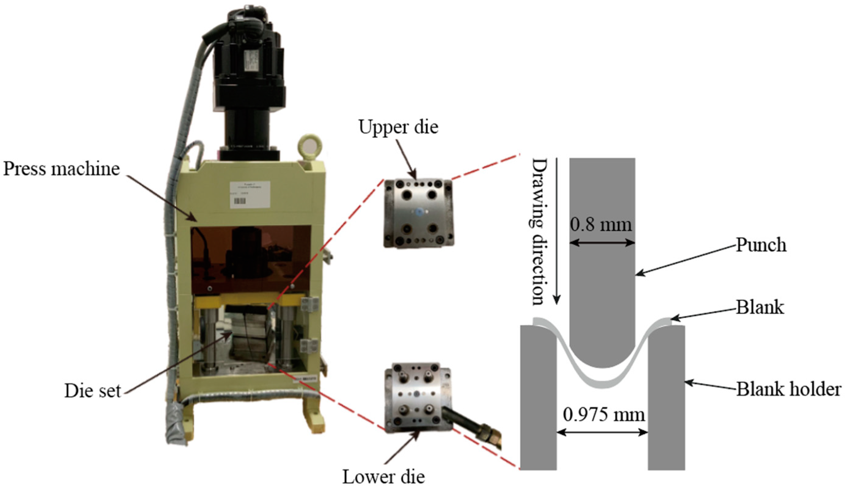
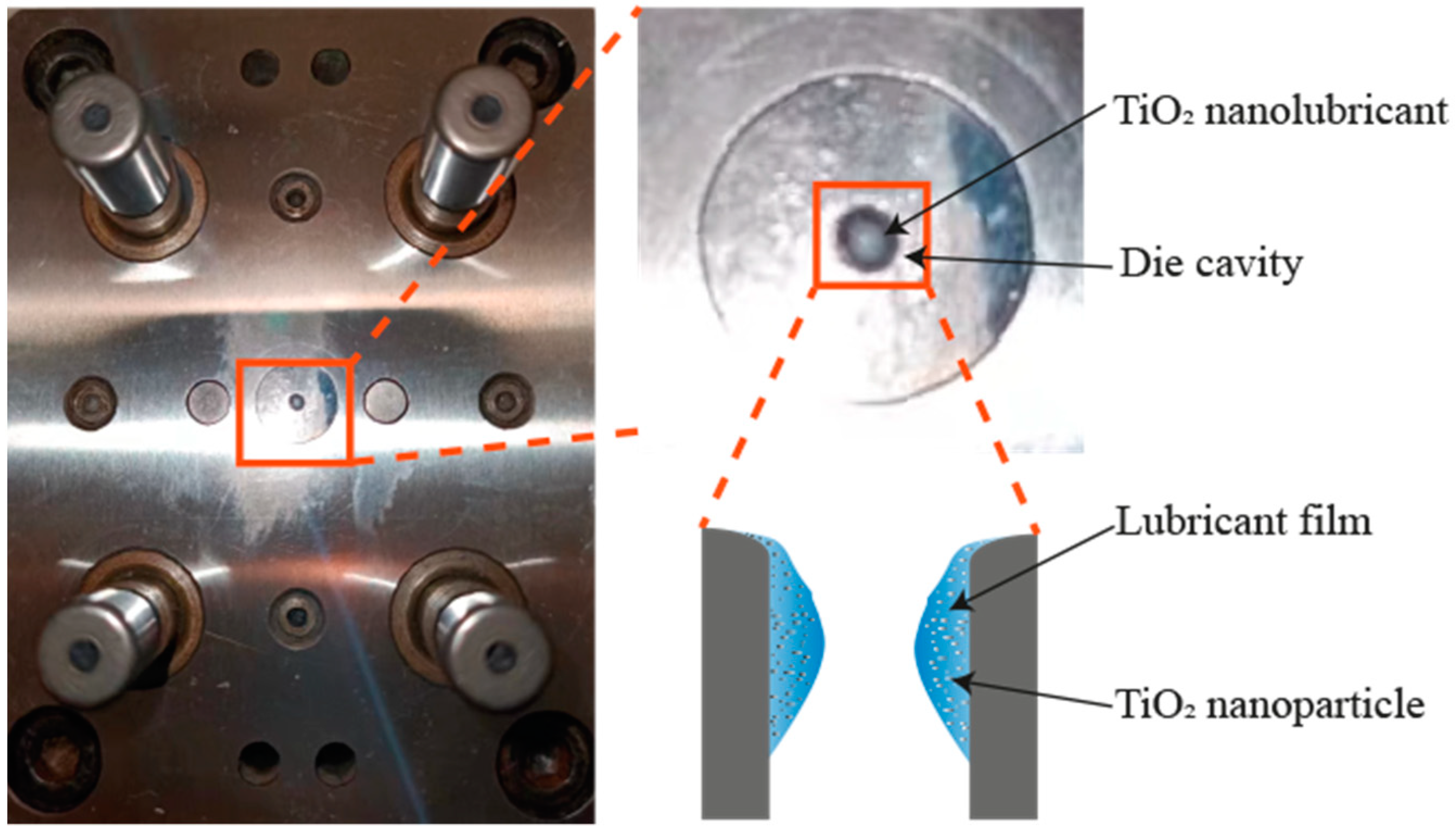
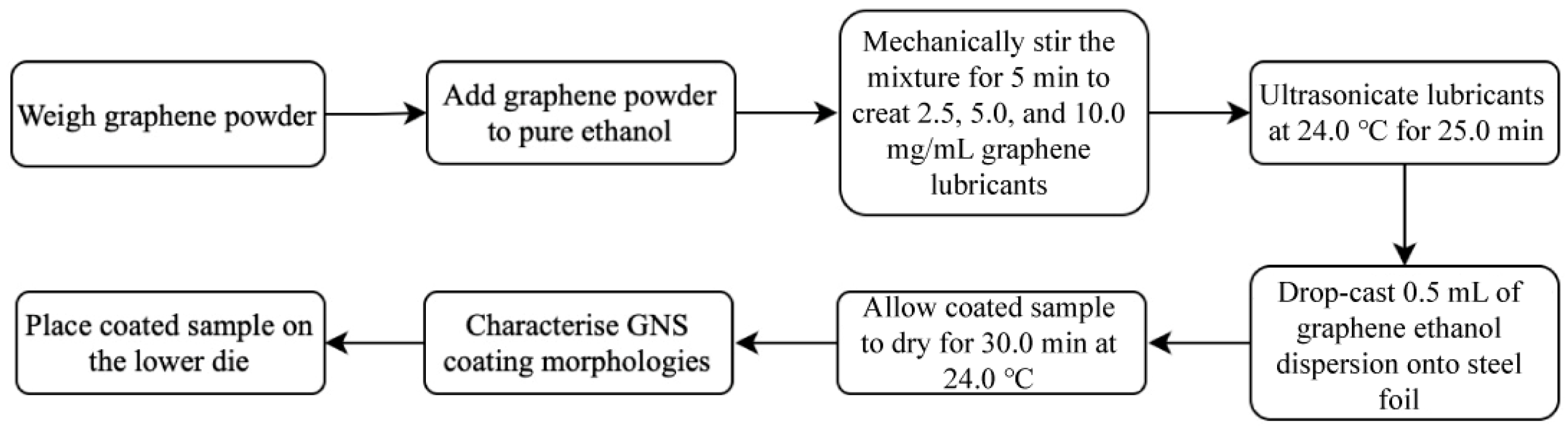
2. Materials and Methods

301 stainless steel foil was selected as the material for investigation, with the material undergoing annealing at 980 °C for 2.0 min to optimise its formability. Following heat treatment, the specimen was cut into 5.0 × 5.0 mm rectangular sections, which were then subjected to MDD tests. The chemical composition of the SUS301 stainless steel is detailed in Table 2. Following annealing, the foils displayed a measured average yield strength of 387 ± 10 MPa. The MDD tests, conducted with a DT30W press machine featuring a comprehensive die set, including upper and lower dies. As depicted in Figure 1, the die set featured a punch diameter of 0.8 mm and a die cavity diameter of 0.975 mm. The MDD technique involves two separate forming stages: blanking and drawing. During the blanking stage, the lower blank holder operates as a punch, accurately carving out a circular blank from the sample under process. Following this, the circular blank is pressed into the die cavity by the punch located in the upper die, drawing a microcup.
The glycerol-based lubricants containing 2.0 wt% of TiO2 NPs was prepared for use in the MDD test. In the lubricant preparation process, a precise quantity of pure TiO2 NPs (P25, obtained from Sigma-Aldrich™, St. Louis, MO, USA, with an estimated diameter of 20.0 nm) was meticulously measured and incorporated into 17.6 wt% distilled water. The mixture was subsequently subjected to mechanical stirring for a duration of 10.0 min. Following this, 0.4 wt% of polyethyleneimine (PEI) was introduced as a dispersion agent, succeeded by centrifugation conducted at a speed of 2000 rpm for another 10.0 min. Thereafter, 80.0 wt% glycerol was gradually dropped into the solution. The mixture was mechanically stirred at a velocity of 2000 rpm for a duration of 10.0 min, subsequently subjected to ultrasonication for an extra 10.0 min to guarantee thorough breakdown of any persisting aggregates. This resulted in the final configuration of the lubricant, which had a weight of 50.0 g. Before commencing the MDD experiments, the die cavity was filled with approximately 0.1 mL of TiO2 nanolubricant, as depicted in Figure 2.
For the utilisation of graphene lubricant, the samples were coated with a graphene film by dipping an ethanol-based graphene lubricant. Figure 3 shows the experimental configuration for GNS coating. Initially, the graphene powder was weighed and added to the pure ethanol. This mixture was then stirred mechanically for 5.0 min to make 2.5, 5.0, and 10.0 mg/mL graphene lubricants, separately. Before their application, these lubricants were subjected to ultrasonication at a temperature of 24.0 °C for a period of 25.0 min. To coat the steel foil, a syringe was used to drop an approximately 0.5 mL graphene lubricant. The treated surface was dried in the air for a duration of 30.0 min at 24.0 °C. Following solvent evaporation, a thin GNS film was mechanically adhered to the substrate. The structural characteristics of the GNS were examined using a field emission scanning electron microscope (SEM). Moreover, the sample coated with GNS was meticulously aligned on the lower die, facilitating direct contact of the coated surface with the die cavity.
The stability of both the TiO2 nanolubricant and graphene lubricants were assessed through a sedimentation test that facilitated the direct visualisation of NP sedimentation. Photographic records of the sedimentation process were captured over a 24 h period to ensure accurate analysis of the stability of each lubricant. The MDD tests were investigated under dry, 2.0 wt% TiO2, 2.5 mg/mL graphene lubricant, 5.0 mg/mL graphene lubricant, 10.0 mg/mL graphene lubricant, 2.0 wt% TiO2 + 2.5 mg/mL graphene lubricant, 2.0 wt% TiO2 + 5.0 mg/mL graphene lubricant, and 2.0 wt% TiO2 + 10.0 mg/mL graphene lubricant lubrication conditions, individually. During the MDD, drawing forces were recorded with a load sensor in the upper die. The drawn microcups were analysed using a 3D laser microscope. Energy-Dispersive X-ray Spectroscopy (EDS) was applied to examine the elemental distribution in the material both before and after MDD, providing insights into the functional mechanisms of the lubricants.

3. Results and Discussion

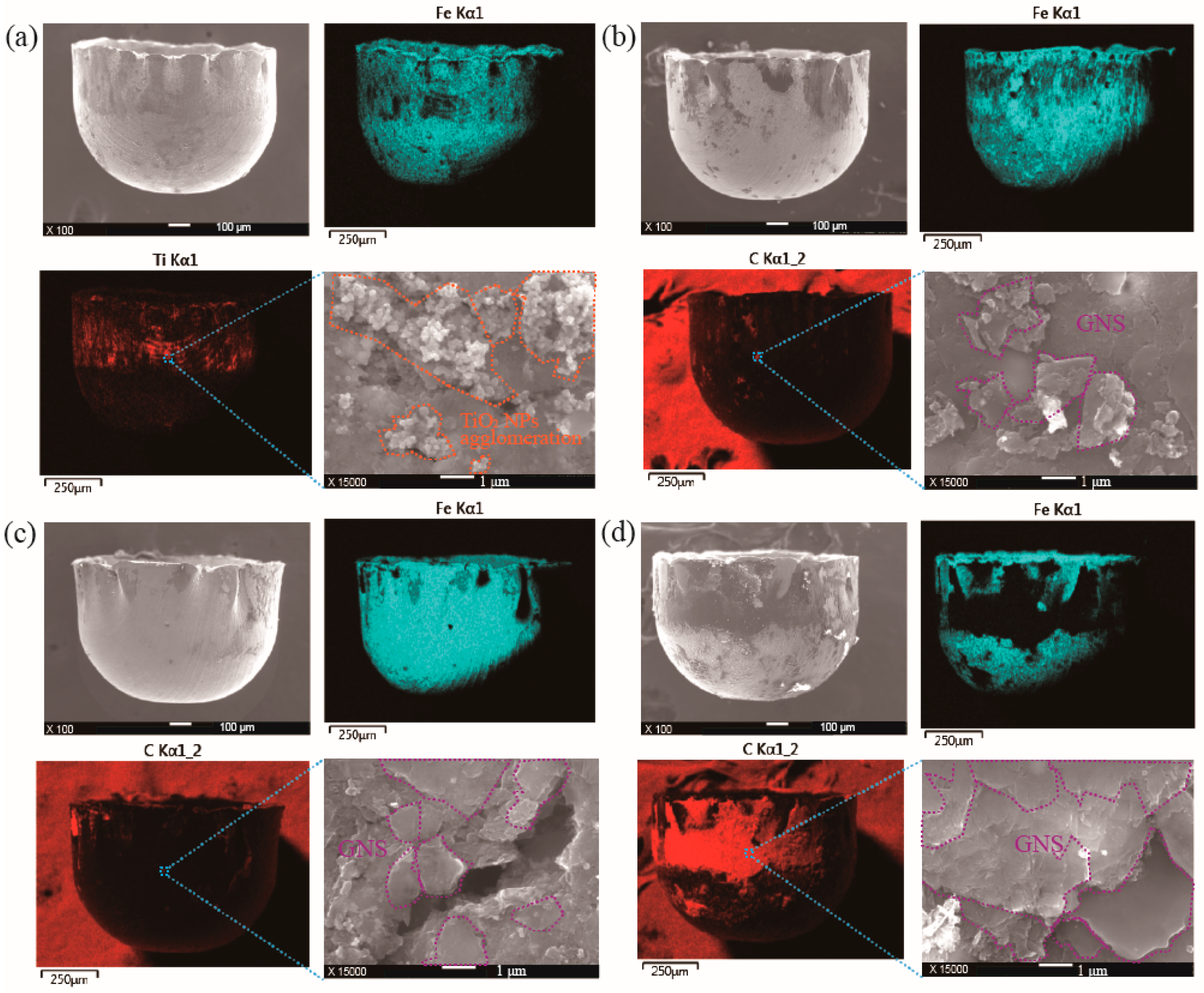
3.1. Characterisation of TiO2 Nanolubricant and Graphene Lubricants

Figure 4 illustrates the sedimentation behaviour of TiO2 nanolubricant and graphene lubricants at varying concentrations and over different time intervals. The results demonstrate that the TiO2 nanolubricant exhibits remarkable stability. Significantly, even post a duration of 40.0 h, the TiO2 NPs largely retained their original position, signifying the exceptional dispersion stability. The precipitation of graphene becomes more prominent with increasing concentration. After 18.0 h, discernible precipitation of graphene was detected in the lubricant with a concentration of 10.0 mg/mL. By the 24.0 h mark, the 5.0 mg/mL graphene lubricant exhibited pronounced precipitation. Following a duration of 40.0 h, both the 5.0 mg/mL and 10.0 mg/mL graphene lubricants had undergone complete sedimentation. The 2.5 mg/mL graphene lubricant demonstrated only a scant degree of precipitation after the same period. Consequently, the settling ability of the graphene lubricant is enhanced at higher concentrations.
Figure 5 displays the surface view coated with various graphene lubricants. It reveals that the surface roughness, as represented by the average surface roughness value (Ra), is dependent on the graphene lubrication conditions employed. Surface roughness value is increased by graphene lubricants, an outcome attributed to the incorporation of GNS, which results in a coarser surface texture. The Ra of uncoated area is 0.22 μm, and this value increases to 2.77 μm upon application of a 2.5 mg/mL graphene lubricant coating. With a 5 mg/mL graphene lubricant coating, the Ra decreases to 1.01 μm. Further increasing the concentration to a 10 mg/mL graphene lubricant coating leads to a reduced Ra of 0.53 μm. Interestingly, as the concentration of graphene in the lubricant increases, the Ra decreases. This enhancement in surface topography could be predominantly driven by two interconnected phenomena: the elevated uniformity of the graphene coating and the aggregation of graphene powder on the surface. Increasing graphene concentration in the lubricant markedly reduces surface voids, effectively covering the material and induced irregularities to boost overall smoothness. Simultaneously, the accumulation of the graphene layers could form a uniform coating on the surface. Each layer of GNS is exceptionally thin and flat. So even though there is an accumulation, they stack neatly on top of each other, maintaining an overall smooth surface.
Figure 6 presents EDS maps and SEM images of samples treated with varying concentrations (2.5, 5.0, and 10.0 mg/mL) of graphene lubricant. The distribution of C element attests to the successful integration of graphene, providing evidence of its effective application. At the lower concentration of 2.5 mg/mL, the graphene coating appears less uniform compared to higher graphene concentrations. This inference is supported by the visibility of Fe element on the surface, indicative of incomplete coverage. High-magnification imaging provides further confirmation, showing multilayer GNS with minimal voids across coated regions. Void areas show a decrease in presence with higher graphene concentrations. Additionally, the use of a 10.0 mg/mL graphene lubricant results in a considerable accumulation of graphene. This excess graphene can lead to a pronounced agglomeration, because of Van der Waals forces. As the concentration of graphene increases, the interaction between graphene and TiO2 nanolubricant may be disrupted. An excessive amount of graphene could overload the system, leading to a dominance of graphene-graphene interactions over the beneficial interactions between graphene and TiO2.

3.2. Drawing Force

Figure 7 shows the correlation between the drawing force and displacement across various lubrication conditions. The MDD generally initiates with a bending stage: the edges of the blank are drawn into the die and subsequently begin to bend. Initially driven by bending resistance, the blank incrementally conforms to the die, evolving from bent to final drawn form after bending. As this transition occurs, there is a consequent increase in the flow stress of the material. In MDD, the point of the maximum drawing force is achieved once the material has undergone large plastic deformation, necessitating the maximum force to continue the deformation process. Drawing involves pushing a metal blank into a die, generating friction that resists deformation. In scenarios of increased friction, a corresponding increase of the drawing force becomes essential to maintain the process. Lubricants serve the crucial function of reducing this friction, facilitating the drawing process. Thus, the lubricant performance could be evaluated by monitoring the peak drawing force. The maximum drawing force was recorded under a variety of lubrication conditions, as shown in Figure 7. Under dry condition, the highest drawing force was 77.56 N, while the use of a 2.0% TiO2 nanolubricant resulted in a decreased force of 72.88 N. With different concentrations of graphene lubricant (2.5, 5.0, and 10.0 mg/mL), recorded the largest drawing forces of 73.45 N, 65.38 N, and 67.71 N were observed, respectively. Figure 8 presents EDS maps and an SEM image of microcups drawn under these lubricants. EDS mapping confirmed non-uniform TiO2 NP distribution on the microcup surface, with a higher concentration in the upper region compared to the bottom area. Additionally, the SEM image reveals significant agglomeration of TiO2 NPs. In the diffusion environment created by the nanolubricant, the NPs move towards areas with a lower shear rate. This movement is motivated by the attempt of NPs to minimise friction. During movement, the NPs cluster together. However, these clusters are dispersed by repulsive forces such as van der Waals interactions, surface charge interactions, double layer formation, and steric hindrance. This dynamic mechanism ensures an even distribution of the TiO2 NPs [29]. In circumstances where graphene lubricant is applied, the microcup surfaces consistently display remnants of C. The presence of the C signifies GNS inclusion on the microcup surface. SEM indicates that the GNS display a sheet-like structure. The graphene accumulation is significant reduced, resulting in a marked reduction of void areas in the coating. These residual GNS facilitate friction reduction, attributable to the ease of inter-layer sliding within multi-layered graphene structures. Notably, a correlation is established between the rise in lubricant concentration and the increase in residual graphene detected on microcup surfaces. With the graphene lubricant concentration increased to 10 mg/mL, a substantial rise in the quantity of residual GNS on the microcups is evident, especially in comparison to those drawn using lower concentrations of 2.5 and 5 mg/mL. The 10 mg/mL graphene lubricant, delivering an ample amount of GNS, emerges as the most effective solution when compared to other graphene lubricant concentrations explored in this study. A combination of these graphene lubricants with the TiO2 nanolubricant led to further reductions in the largest drawing forces to 69.29 N, 63.54 N, and 65.26 N, respectively. When compared to the maximum drawing force under dry conditions, a significant reduction of 18.08% was observed when using a combination of 5.0 mg/mL graphene lubricant and 2.0 wt% TiO2 nanolubricant, underscoring the superior performance of this specific combination among the lubricants tested. Figure 9 presents the surface EDS of microcups drawn under the combined application of different concentrations of graphene and TiO2 nanolubricant. From the figure, it is evident that when TiO2 nano-lubricant and graphene lubricant are employed together, the aggregation of TiO2 visibly decreases compared to when used alone. Graphene steric hindrance and electrostatic repulsion could disrupt TiO2 NP aggregation, enhancing dispersion [29]. This synergy promotes more uniform nanoparticle distribution compared to using TiO2 nanolubrican alone. Consequently, the combined use of these two lubricants results in a more effective outcome than the independent use of each lubricant. The distribution of the Ti provides further insight. Notably, when TiO2 nanolubricant is paired with a 5 mg/mL graphene lubricant, more residual Ti is evident on the microcup surface compared to other concentrations. Furthermore, the aggregation of TiO2 is significantly minimised in this combination. As a result, among all lubricant combinations, the most noticeable friction reduction is achieved when the 5 mg/mL graphene lubricant and TiO2 nanolubricant are used together.

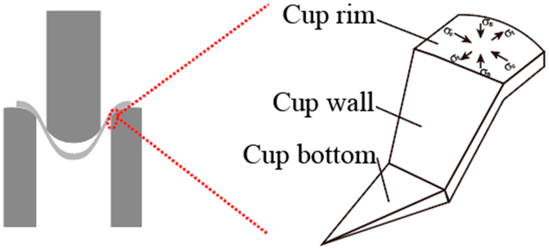
3.3. Effect of Lubricants on Profile of Microcups

The impact of diverse lubricants on the profile of microcups within the MDD was investigated. Figure 10 presents mouth view of the cups formed under various lubrication conditions. Wrinkling, a noteworthy feature in these observations, arises on the mouths of the microcups manufactured under these lubricant conditions. Upon subjection to overstretching, the material may cross its yield threshold, resulting in the wrinkles. These wrinkles affect multiple performance characteristics and properties of the microcups, including their strength, rigidity, resilience to deformation and failure. The application of lubricants could diminish the wrinkle frequency on the microcups. Figure 11 illustrates the force equilibrium condition in a segment of the blank, precisely at its boundary where there exists a propensity for wrinkling to arise. The application of the TiO2 nanolubricant has been found to be particularly effective in reducing wrinkling, outperforming other lubricants used in the MDD. The underlying mechanism of wrinkling is fundamentally determined by the fluctuating stress states at the edge of the blank. To elaborate, the annular part of the blank experiences radial tensile stress (σt), vertical compress stress (σt), and circumferential compressive stress (σc) is generated during the drawing process. Wrinkling is instigated when σc surpasses a critical instability threshold, leading to elastoplastic wave-shaped deformation. Utilising the TiO2 nanolubricant effectively reduce the wrinkling by mitigating the frictional resistance between the blank and die interface, thus decreasing the circumferential compressive stress and lowering the critical instability point. In contrast, the synergistic use of TiO2 nanolubricant and a 5.0 mg/mL graphene lubricant significantly decreases the drawing force, although it does not suppress wrinkling as effectively as the sole application of TiO2 nanolubricant. This phenomenon can be attributed to the introduction of the graphene lubricant. Under the intense pressure exerted by the rim, this lubricant might lead to surface irregularities, which could result in inconsistent material properties. Such non-uniformity may result in uneven deformation, subsequently causing wrinkling.
Figure 12 presents a side view of microcups produced under various lubrication conditions. it is evident that a distinct inconsistency occurs in the uniformity of the vertical dimensions. The potential repercussions of such unevenness are substantial, posing risks to the structural integrity, functionality, and precision of these microcups. The results reveal that the applications of 5.0 and 10.0 mg/mL graphene lubricants significantly ameliorate this height discrepancy in the microcups. A further enhancement in uniformity was observed when graphene lubricants, at concentrations of 5.0 and 10.0 mg/mL, were paired with TiO2 nanolubricant. A combination of 2.5 mg/mL graphene lubricant and TiO2 nanolubricant resulted in a microcup exhibiting nonuniform characteristics. This outcome implies the significance of the lubricant concentration in determining the comprehensive performance of the lubricant. When a synthesis of 5.0 mg/mL graphene lubricant and TiO2 nanolubricant was applied, the most even microcup was observed. The contact area between the material and die cavity exceeds that of the edge of the blank. Thus, the synthesised applications of graphene lubricant and TiO2 nanolubricant can alleviate the irregularity of friction. This leads to a more consistent deformation since the material can spread over areas with even lubrication. As a result, it directly influences the height uniformity of the microcup.

4. Conclusions

To conclude, this study offers insights into the use of SUS 301 foil in MDD trials, by capitalising on the TiO2 nanolubricant and ethanol-based graphene lubricants. Below, the conclusions are shown:
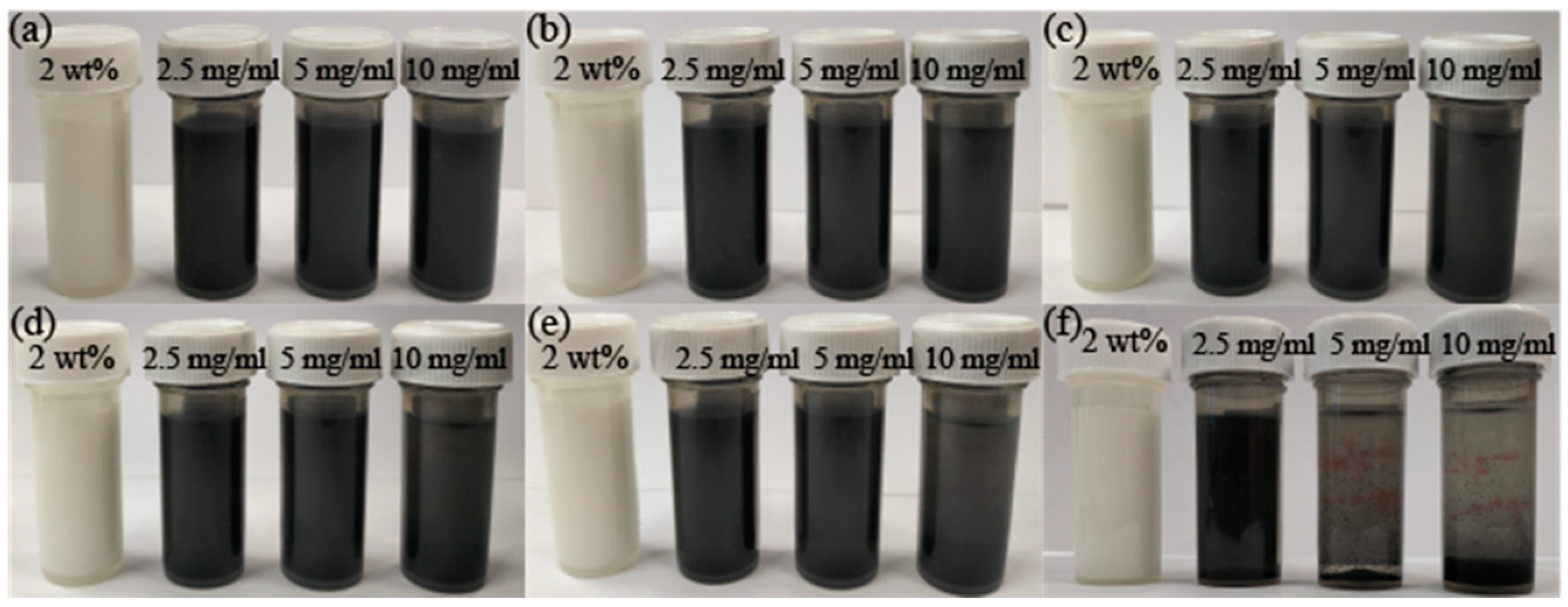
  • The TiO2 nanolubricant shows extraordinary stability and dispersion within a glycerol-based environment, conserving its constitution even over extended durations. In contrast, the graphene lubricants showed sedimentation tendencies as concentration increased, which necessitates meticulous regulation of lubricant formulation and administration. After 40.0 h, both the 5.0 mg/mL and 10.0 mg/mL graphene lubricants fully sedimented, while the 2.5 mg/mL lubricant showed minimal precipitation.
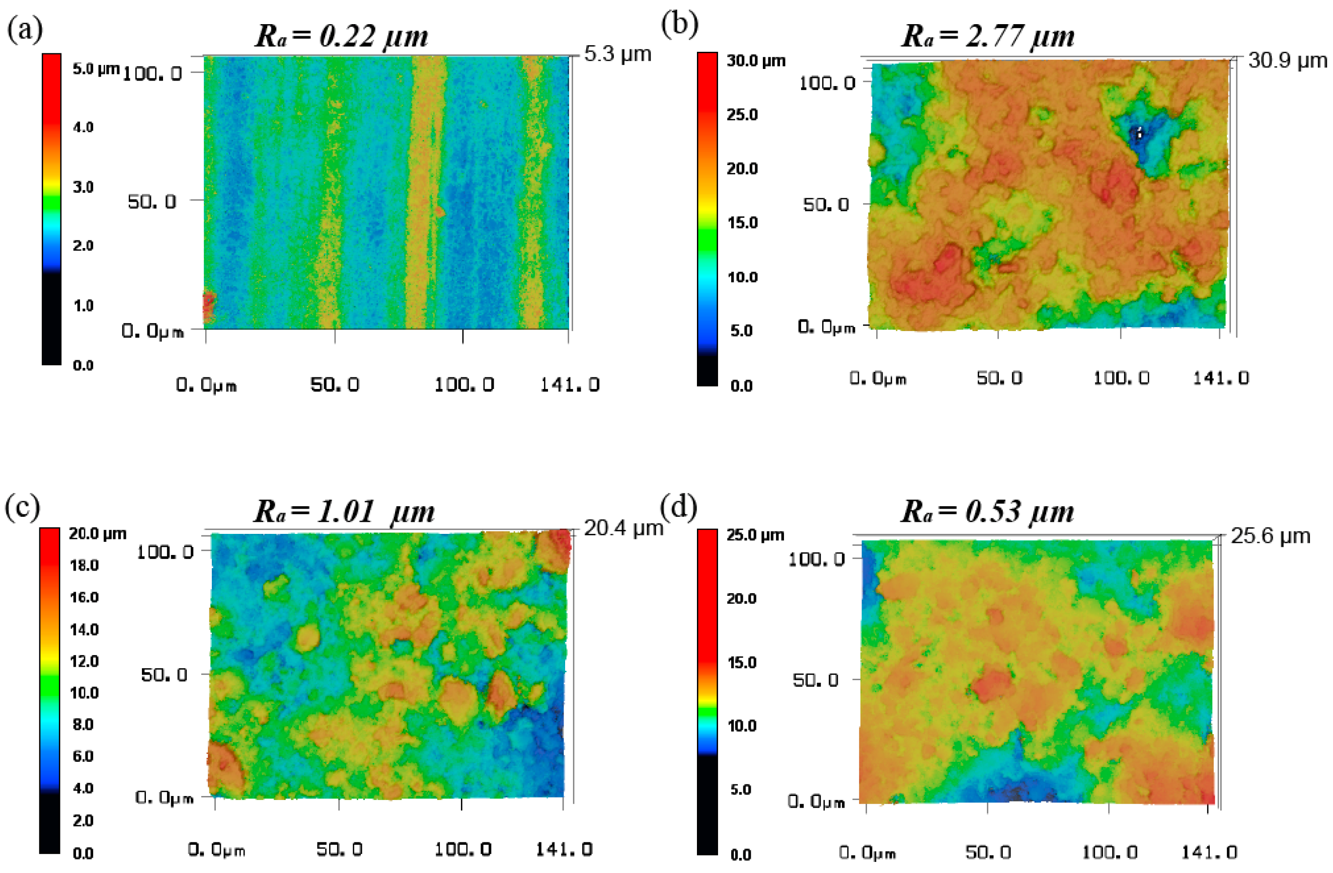
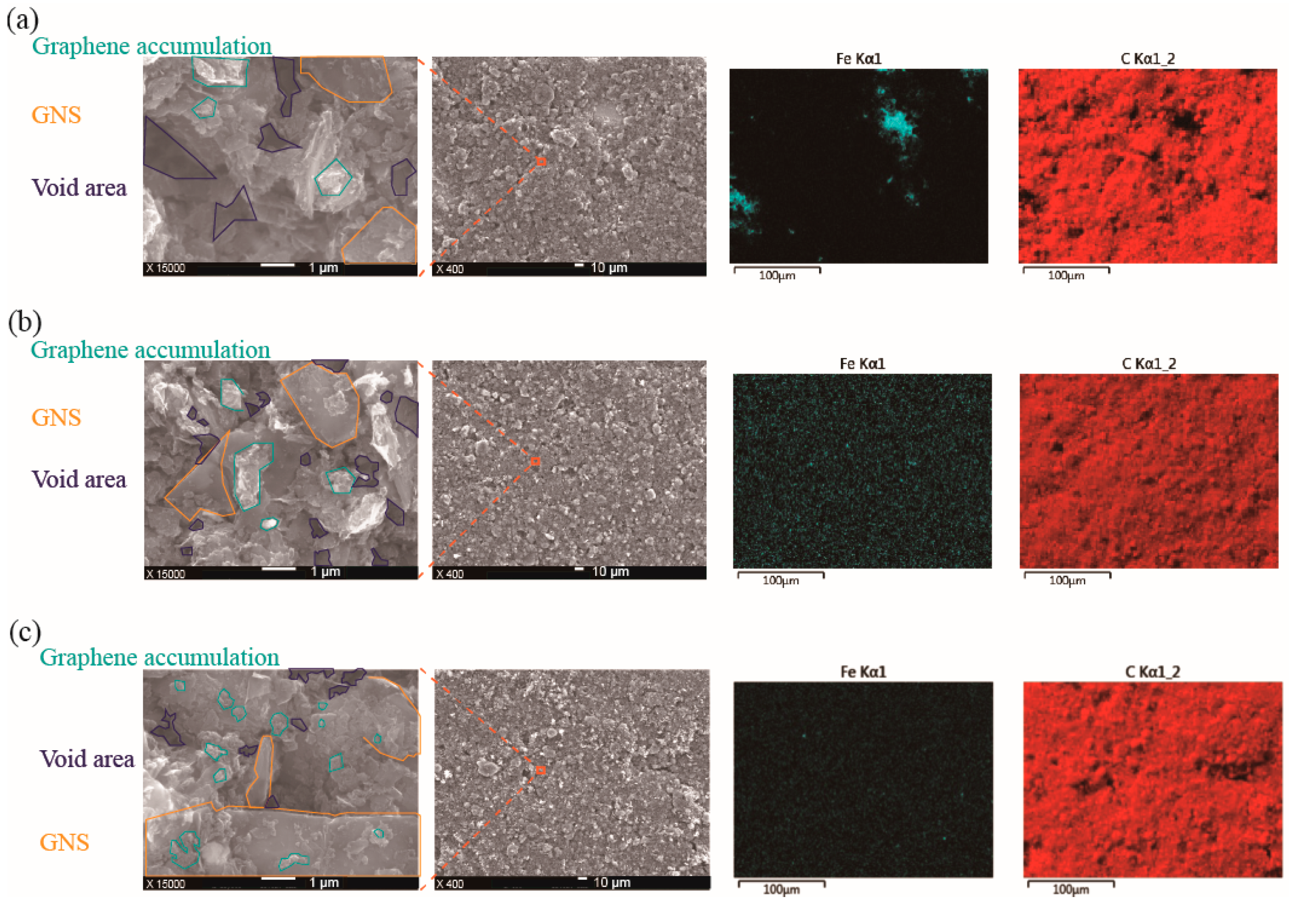
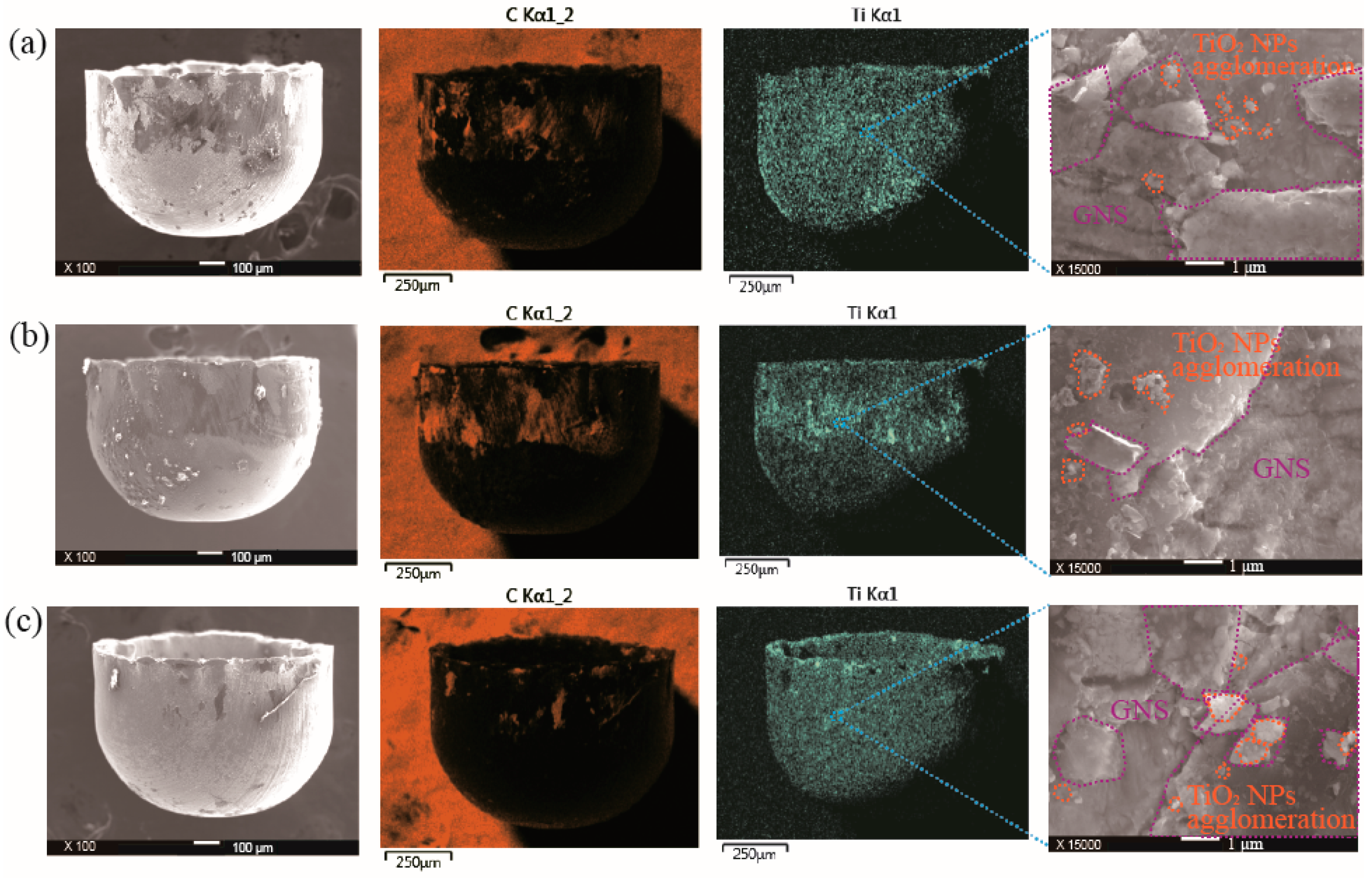
  • When coating the GNS with escalated graphene concentrations, surface topography becomes superior. The Ra decreases from 2.77 μm to 0.53 μm with an increase in graphene lubricant concentration from 2.5 mg/mL to 10 mg/mL. This behavior is primarily driven by the advanced uniformity of the graphene coating and the buildup of graphene powder on the surface, thereby decreasing surface irregularities and promoting smoothness.
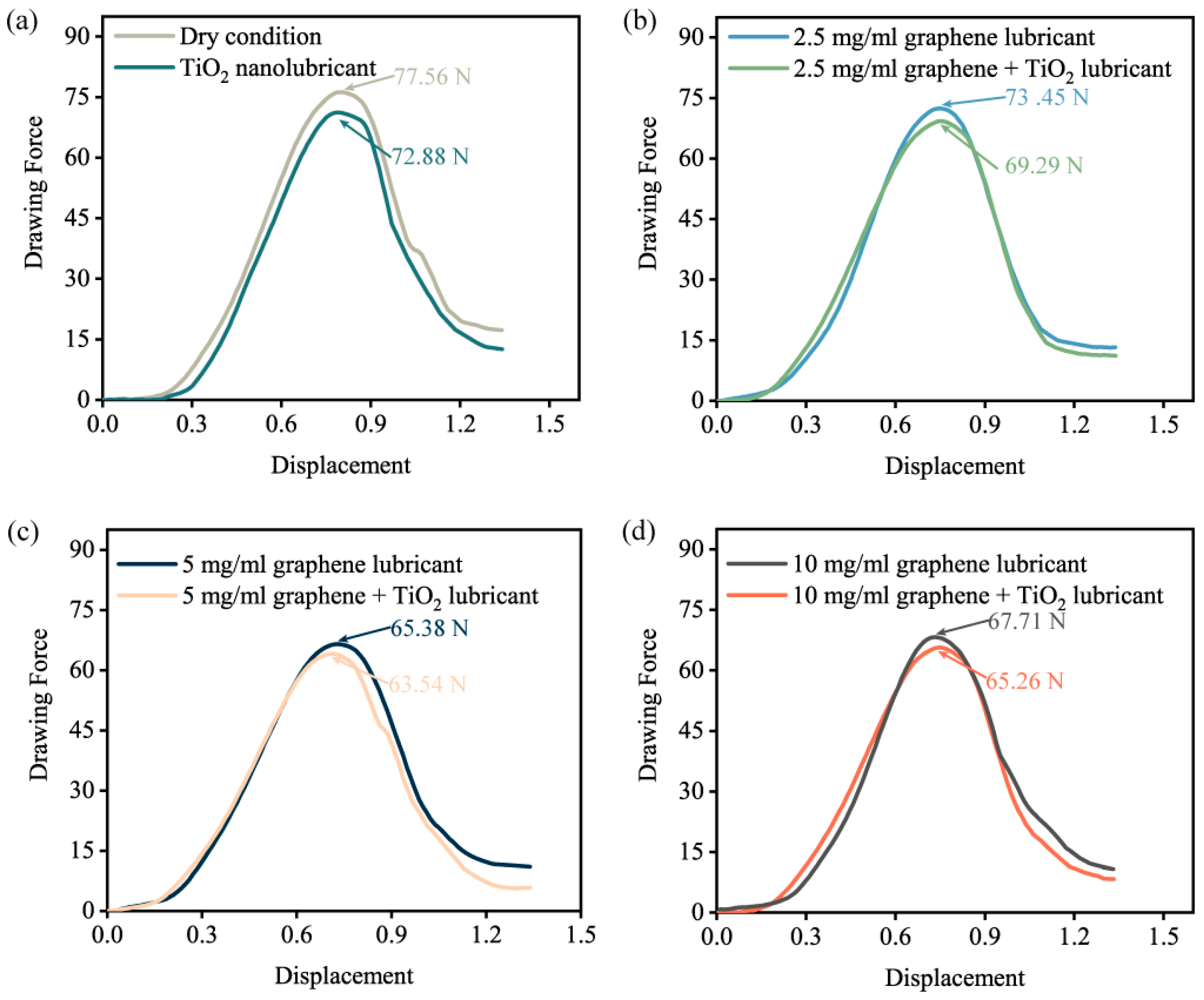
  • Employing peak drawing force as a surrogate indicator for lubricant efficiency revealed that a diminished force signifies reduced friction and enhanced lubricant performance. Remarkably, a substantial decrement in drawing force was recorded when utilising a 5.0 mg/mL graphene lubricant and TiO2 nanolubricants concurrently, signifying the synergistic efficacy of this combination over standalone lubricants. Under dry condition, the peak drawing force measured 77.56 N. However, with the combined application of TiO2 nanolubricant and 5 mg/mL graphene lubricant, this force reduced to 63.54 N.
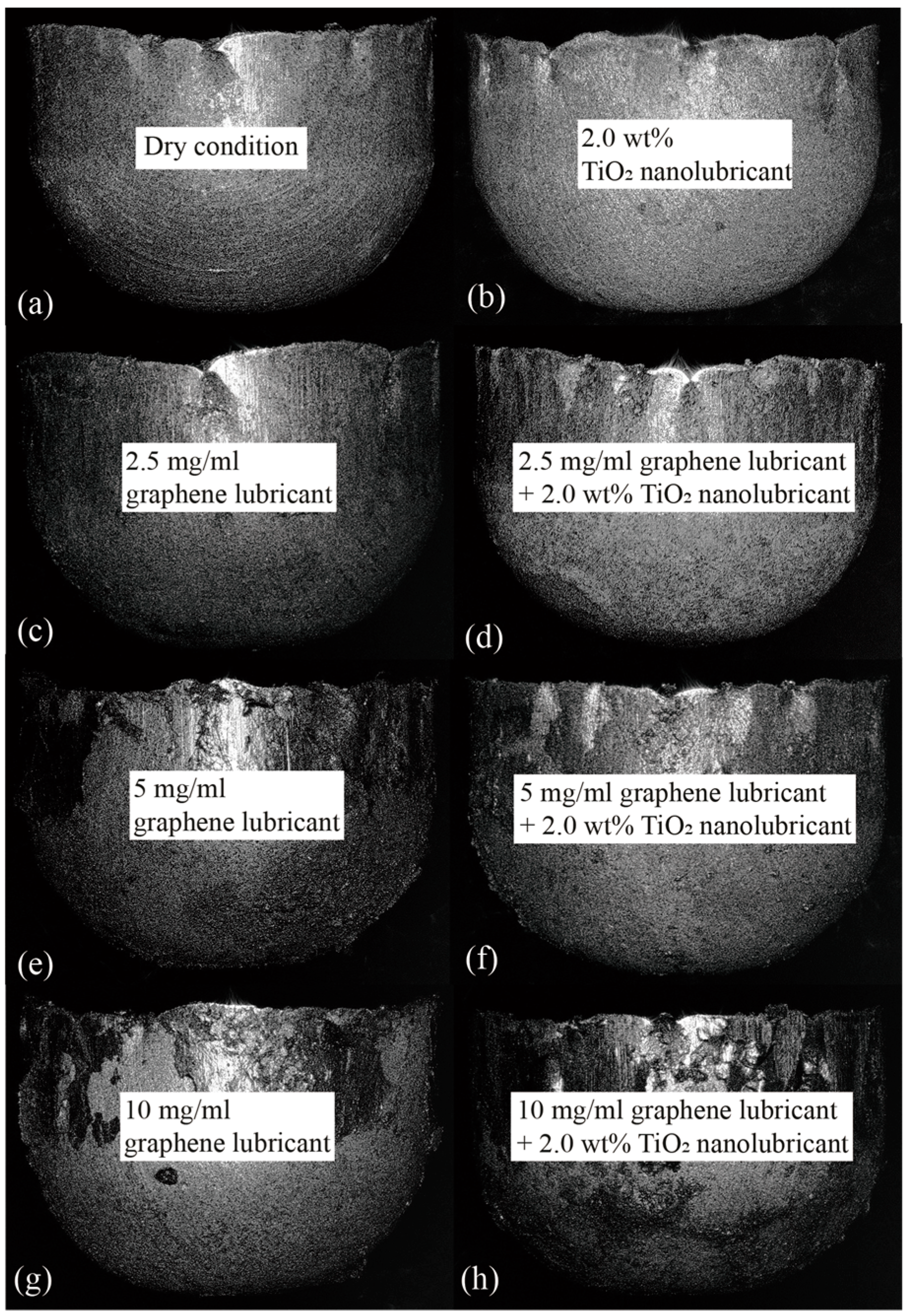
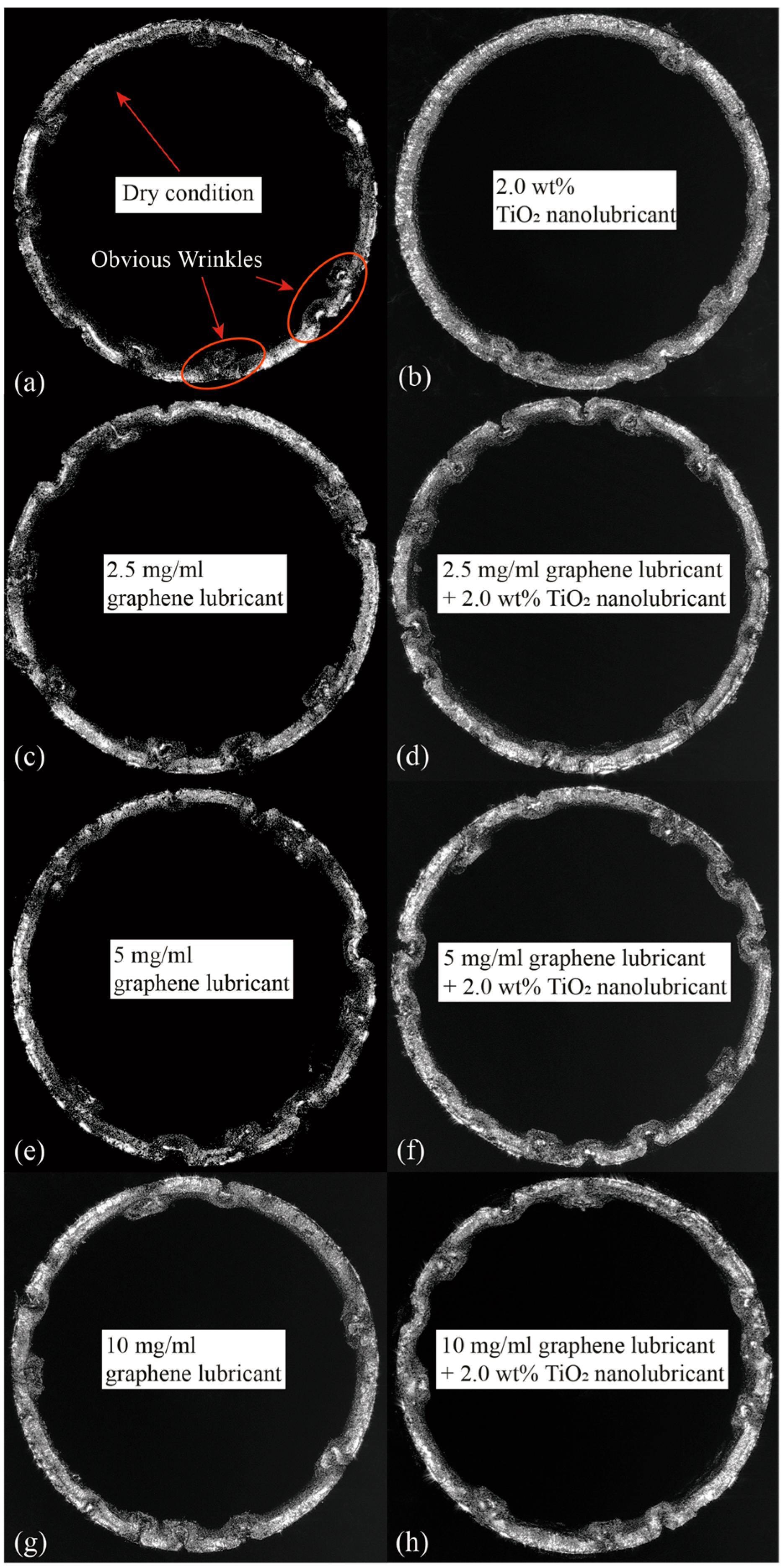
  • The application of 2.0 wt% TiO2 nanolubricant was notably successful in reducing wrinkling. Analysis of the vertical dimensions of the generated microcups indicated marked improvement in height uniformity when using graphene lubricant at concentrations of 5.0 mg/mL, especially when paired with TiO2 nanolubricant.

Author Contributions

Conceptualization, D.P. and G.Z.; methodology, D.P., F.J. and Y.L.; software, F.J., Y.L. and D.P.; validation, J.W., Z.L., Y.L. and L.L.; formal analysis, D.P., J.W., Z.L. and G.Z.; investigation, G.Z., Y.L., J.W. and L.L.; resources, Z.L., F.J., G.Z., L.L. and Z.J.; data curation, D.P., F.J. and M.Y.; writing—original draft preparation, D.P.; writing—review and editing, F.J., J.W. and Z.L.; visualization, M.Y.; supervision, Z.J.; project administration, M.Y. and Z.J.; funding acquisition, M.Y. and Z.J. All authors have read and agreed to the published version of the manuscript.

Funding

This project is supported by the Australian Research Council (DP190100738).

Data Availability Statement

The datasets generated and/or analysed during this research can be obtained from the corresponding author upon a reasonable request.

Acknowledgments

Special thanks are extended to [Faculty of Engineering and Information Sciences University of Wollongong] and its dedicated staff for providing access to essential facilities and equipment.

Conflicts of Interest

The authors declare no conflict of interest.

References

  1. Jia, F.; Zhao, J.; Luo, L.; Xie, H.; Jiang, Z. Experimental and numerical study on micro deep drawing with aluminium-copper composite material. Procedia Eng. 2017, 207, 1051–1056. [Google Scholar] [CrossRef]
  2. Jiang, Z.; Zhao, J.; Xie, H. Microforming Technology: Theory, Simulation and Practice; Academic Press: Cambridge, MA, USA, 2017. [Google Scholar]
  3. Raja, C.P.; Ramesh, T. Influence of size effects and its key issues during microforming and its associated processes—A review. Eng. Sci. Technol. Int. J. 2021, 24, 556–570. [Google Scholar]
  4. Gong, F.; Guo, B.; Wang, C.J.; Shan, D.B. Effects of lubrication conditions on micro deep drawing. Microsyst. Technol. 2010, 16, 1741–1747. [Google Scholar] [CrossRef]
  5. Kamali, H.; Xie, H.; Zhao, H.; Jia, F.; Wu, H.; Jiang, Z. Frictional size effect of light-weight Mg–Li alloy in micro deep drawing under nano-particle lubrication condition. Mater. Trans. 2020, 61, 239–243. [Google Scholar] [CrossRef]
  6. Cortes, V.; Sanchez, K.; Gonzalez, R.; Alcoutlabi, M.; Ortega, J.A. The performance of SiO2 and TiO2 nanoparticles as lubricant additives in sunflower oil. Lubricants 2020, 8, 10. [Google Scholar] [CrossRef]
  7. Birleanu, C.; Pustan, M.; Cioaza, M.; Molea, A.; Popa, F.; Contiu, G. Effect of TiO2 nanoparticles on the tribological properties of lubricating oil: An experimental investigation. Sci. Rep. 2022, 12, 5201. [Google Scholar] [CrossRef] [PubMed]
  8. Asrul, M.; Zulkifli, N.; Masjuki, H.; Kalam, M. Tribological properties and lubricant mechanism of nanoparticle in engine oil. Procedia Eng. 2013, 68, 320–325. [Google Scholar] [CrossRef]
  9. Luo, L.; Jiang, Z.; Wei, D.; Jia, F. A study of influence of hydraulic pressure on micro-hydromechanical deep drawing considering size effects and surface roughness. Wear 2021, 477, 203803. [Google Scholar] [CrossRef]
  10. Kamali, H.; Xie, H.; Jia, F.; Wu, H.; Zhao, H.; Zhang, H.; Li, N.; Jiang, Z. Effects of nano-particle lubrication on micro deep drawing of Mg-Li alloy. Int. J. Adv. Manuf. Technol. 2019, 104, 4409–4419. [Google Scholar] [CrossRef]
  11. Seyedzavvar, M.; Abbasi, H.; Kiyasatfar, M.; Ilkhchi, R.N. Investigation on tribological performance of CuO vegetable-oil based nanofluids for grinding operations. Adv. Manuf. 2020, 8, 344–360. [Google Scholar] [CrossRef]
  12. Huo, M.; Wu, H.; Xie, H.; Zhao, J.; Su, G.; Jia, F.; Li, Z.; Lin, F.; Li, S.; Zhang, H.; et al. Understanding the role of water-based nanolubricants in micro flexible rolling of aluminium. Tribol. Int. 2020, 151, 106378. [Google Scholar] [CrossRef]
  13. Wu, H.; Jia, F.; Zhao, J.; Huang, S.; Wang, L.; Jiao, S.; Huang, H.; Jiang, Z. Effect of water-based nanolubricant containing nano-TiO2 on friction and wear behaviour of chrome steel at ambient and elevated temperatures. Wear 2019, 426, 792–804. [Google Scholar] [CrossRef]
  14. Ali, M.K.A.; Xianjun, H.; Mai, L.; Qingping, C.; Turkson, R.F.; Bicheng, C. Improving the tribological characteristics of piston ring assembly in automotive engines using Al2O3 and TiO2 nanomaterials as nano-lubricant additives. Tribol. Int. 2016, 103, 540–554. [Google Scholar] [CrossRef]
  15. Chang, H.; Li, Z.; Kao, M.; Huang, K.; Wu, H. Tribological property of TiO2 nanolubricant on piston and cylinder surfaces. J. Alloys Compd. 2010, 495, 481–484. [Google Scholar] [CrossRef]
  16. Le, V.N.-A.; Lin, J.-W. Tribological properties of aluminum nanoparticles as additives in an aqueous glycerol solution. Appl. Sci. 2017, 7, 80. [Google Scholar] [CrossRef]
  17. Nawaz, R.; Kait, C.F.; Chia, H.Y.; Isa, M.H.; Huei, L.W. Glycerol-mediated facile synthesis of colored titania nanoparticles for visible light photodegradation of phenolic compounds. Nanomaterials 2019, 9, 1586. [Google Scholar] [CrossRef]
  18. Wu, H.; Zhao, J.; Cheng, X.; Xia, W.; He, A.; Yun, J.-H.; Huang, S.; Wang, L.; Huang, H.; Jiao, S.; et al. Friction and wear characteristics of TiO2 nano-additive water-based lubricant on ferritic stainless steel. Tribol. Int. 2018, 117, 24–38. [Google Scholar] [CrossRef]
  19. Wu, H.; Zhao, J.; Xia, W.; Cheng, X.; He, A.; Yun, J.H.; Wang, L.; Huang, H.; Jiao, S.; Huang, L.; et al. Analysis of TiO2 nano-additive water-based lubricants in hot rolling of microalloyed steel. J. Manuf. Process. 2017, 27, 26–36. [Google Scholar] [CrossRef]
  20. Azman, S.S.N.; Zulkifli, N.W.M.; Masjuki, H.; Gulzar, M.; Zahid, R. Study of tribological properties of lubricating oil blend added with graphene nanoplatelets. J. Mater. Res. 2016, 31, 1932–1938. [Google Scholar] [CrossRef]
  21. Alghani, W.; Ab Karim, M.S.; Bagheri, S.; Amran, N.A.M.; Gulzar, M. Enhancing the tribological behavior of lubricating oil by adding TiO2, graphene, and TiO2/graphene nanoparticles. Tribol. Trans. 2019, 62, 452–463. [Google Scholar] [CrossRef]
  22. Zhao, W.; Ci, X. TiO2 nanoparticle/fluorinated reduced graphene oxide nanosheet composites for lubrication and wear resistance. ACS Appl. Nano Mater. 2020, 3, 8732–8741. [Google Scholar] [CrossRef]
  23. Wei, Y.-K.; Dai, L.-Y.; Zhong, H.-C.; Liao, H.-F.; Hou, X.-B. Preparation and Tribological Properties of a Multilayer Graphene-Reinforced TiO2 Composite Nanolubricant Additive. ACS Omega 2022, 7, 42242–42255. [Google Scholar] [CrossRef] [PubMed]
  24. Jin, B.; Chen, G.; He, Y.; Zhang, C.; Luo, J. Lubrication properties of graphene under harsh working conditions. Mater. Today Adv. 2023, 18, 100369. [Google Scholar] [CrossRef]
  25. Kasar, A.K.; Menezes, P.L. Synthesis and recent advances in tribological applications of graphene. Int. J. Adv. Manuf. Technol. 2018, 97, 3999–4019. [Google Scholar] [CrossRef]
  26. Kim, K.-S.; Lee, H.-J.; Lee, C.; Lee, S.-K.; Jang, H.; Ahn, J.-H.; Kim, J.-H.; Lee, H.-J. Chemical vapor deposition-grown graphene: The thinnest solid lubricant. ACS Nano 2011, 5, 5107–5114. [Google Scholar] [CrossRef]
  27. Feng, X.; Kwon, S.; Park, J.Y.; Salmeron, M. Superlubric sliding of graphene nanoflakes on graphene. ACS Nano 2013, 7, 1718–1724. [Google Scholar] [CrossRef]
  28. Cho, D.-H.; Wang, L.; Kim, J.-S.; Lee, G.-H.; Kim, E.S.; Lee, S.; Lee, S.Y.; Hone, J.; Lee, C. Effect of surface morphology on friction of graphene on various substrates. Nanoscale 2013, 5, 3063–3069. [Google Scholar] [CrossRef]
  29. Jang, T.; Park, S.J.; Lee, J.E.; Yang, J.; Park, S.; Jun, M.B.; Kim, Y.W.; Aranas, C.; Choi, J.P.; Zou, Y.; et al. Topography-Supported Nanoarchitectonics of Hybrid Scaffold for Systematically Modulated Bone Regeneration and Remodeling. Adv. Funct. Mater. 2022, 32, 2206863. [Google Scholar] [CrossRef]
Figure 1. DT30W press machine and die set utilised in MDD.
Processes 11 03042 g001
Figure 2. Application of TiO2 nanolubricant in MDD experiments.
Processes 11 03042 g002
Figure 3. Preparation and coating process of GNS on steel foil using ethanol-based graphene lubricant.
Processes 11 03042 g003
Figure 4. Time-dependent sedimentation behaviour of the TiO2 nanolubricant and graphene lubricants at various concentrations: (a) initial State, (b) 8.0 h, (c) 16.0 h, (d) 24.0 h, (e) 32.0 h, and (f) 40.0 h.
Processes 11 03042 g004
Figure 5. Influence of graphene lubricant on surface roughness and texture across various concentrations: (a) dry, (b) 2.5 mg/mL, (c) 5.0 mg/mL, and (d) 10.0 mg/mL graphene lubricant treatments.
Processes 11 03042 g005
Figure 6. Influence of differing graphene lubricant concentrations on surface topography and elemental composition: SEM images and EDS mapping of (a) 2.5 mg/mL, (b) 5.0 mg/mL, and (c) 10.0 mg/mL graphene lubricant treatments.
Processes 11 03042 g006
Figure 7. Drawing force-displacement curves in micro deep drawing under different lubrication conditions: (a) dry and TiO2 nanolubricant; (b) 2.5 mg/mL graphene lubricant and 2.5 mg/mL graphene lubricant + TiO2 nanolubricant; (c) 5.0 mg/mL graphene lubricant and 5.0 mg/mL graphene lubricant + TiO2 nanolubricant; and (d) 10.0 mg/mL graphene lubricant and 10.0 mg/mL graphene lubricant + TiO2 nanolubricant.
Processes 11 03042 g007
Figure 8. EDS and SEM analysis of microcups drawn under TiO2 nanolubricant and graphene lubricants: (a) TiO2 nanolubricant, (b) 2.5 mg/mL graphene lubricant, (c) 5 mg/mL graphene lubricant, and (d) 10 mg/mL graphene lubricant.
Processes 11 03042 g008
Figure 9. EDS and SEM analysis of microcups drawn under the combined use of various concentrations of graphene lubricant and TiO2 nanolubricant: (a) 2.5 mg/mL graphene lubricant + TiO2 nanolubricant, (b) 5 mg/mL graphene lubricant + TiO2 nanolubricant, and (c) 10 mg/mL graphene lubricant + TiO2 nanolubricant.
Processes 11 03042 g009
Figure 10. Comparative evaluation of wrinkle manifestations in microcups under varied lubrication conditions: (a) dry, (b) TiO2 nanolubricant, (c) 2.5 mg/mL graphene lubricant, (d) 2.5 mg/mL graphene lubricant + TiO2 nanolubricant, (e) 5.0 mg/mL graphene lubricant, (f) 5.0 mg/mL graphene lubricant + TiO2 nanolubricant, (g) 10.0 mg/mL graphene lubricant, and (h) 10.0 mg/mL graphene lubricant + TiO2 nanolubricant.
Processes 11 03042 g010
Figure 11. Force equilibrium and wrinkle propensity at the blank edge.
Processes 11 03042 g011
Figure 12. Comparative analysis of microcup vertical uniformity under varying lubrication conditions: (a) dry, (b) TiO2 nanolubricant, (c) 2.5 mg/mL graphene lubricant, (d) 2.5 mg/mL graphene lubricant + TiO2 nanolubricant, (e) 5.0 mg/mL graphene lubricant, (f) 5.0 mg/mL graphene lubricant + TiO2 nanolubricant, (g) 10.0 mg/mL graphene lubricant, and (h) 10.0 mg/mL graphene lubricant + TiO2 nanolubricant.
Processes 11 03042 g012
Table 1. Methods to reduce friction and enhance product quality.
ReferencesResearch MethodLubricantsFindings
Cortes et al. [6]Block-on-ring sliding testsSunflower oil based TiO2 and SiO2 nanolubricantCoefficient of friction decreased by 93.7% (TiO2) and 77.7% (SiO2) compared to base sunflower oil.
Birleanu et al. [7]Four balls tribological testOil based TiO2 nanolubricantThe 0.075 %TiO2 nanolubricant reduced the COF by around 60% compared to pure base oil.
Asrul et al. [8]Four balls tribological testParaffin based CuO nanolubricantThe friction coefficient for 3% CuO nanolubricant was 0.123.
Luo et al. [9]MDDHydraulic oilUtilising hydraulic oil is a promising approach to reduce friction in MDD
Kamali et al. [10]MDDOil, and TiO2 nanolubricantTiO2 nanolubricant exhibited superior tribological performance compared to the oil
Table 2. Chemical compositions of SUS301 (wt%).
SiCrMnCNiSPNFe
0.7516.00–18.002.000.156.00–8.000.0300.0450.10Balance
Disclaimer/Publisher’s Note: The statements, opinions and data contained in all publications are solely those of the individual author(s) and contributor(s) and not of MDPI and/or the editor(s). MDPI and/or the editor(s) disclaim responsibility for any injury to people or property resulting from any ideas, methods, instructions or products referred to in the content.

