1. Introduction
Helicopters have become increasingly prevalent in a variety of fields, including medical services, transportation, reconnaissance, and search and rescue missions, thanks to their unique capabilities, such as vertical takeoff and landing, hovering, and unrestricted mobility. As a result, the general public’s awareness and comprehension of helicopters and their applications have grown substantially in recent years.
Nevertheless, one persistent challenge that has garnered significant focus in the helicopter industry is the issue of vibration. This phenomenon not only poses a considerable risk to the reliability and safe functioning of the equipment but also contributes to noise pollution that can be detrimental to the physical and mental health of personnel inside the cabin and those residing in the surrounding areas. Furthermore, the overall comfort and stealth performance of helicopters can be negatively impacted by vibrations as well. The periodic motion of the main rotor blades is the main source of vibration for helicopters. The 24 Hz is a typical vibration frequency of the main rotor system. The maximum response of the helicopter comes from the main vibration frequency. Given the potential hazards associated with helicopter vibrations, particularly at the typical resonant frequency of approximately
, it has become imperative to address this issue to achieve optimal performance and increased safety throughout helicopter operations [
1,
2,
3,
4]. By developing effective vibration control strategies and implementing advanced materials and technologies, it is possible to reduce the impact of vibrations on helicopters, thereby enhancing the performance, safety, and comfort of their aerial operations across a wide range of applications.
Extensive research has been conducted by engineers to minimize helicopter fuselage vibrations, resulting in the development of several effective vibration control methods. However, the advent of high-speed helicopters has presented new challenges, as the rigid rotor configuration and increased forward flight speed contribute to higher vibration loads transmitted to the fuselage. Consequently, vibration control in the helicopter cockpit has become more demanding. Thus, reducing helicopter vibration levels further remains a key research objective in the field. Helicopter vibration control methods can be categorized into active vibration control and passive vibration control, based on the energy drive requirements. During the helicopter design process, suitable vibration control methods can be chosen to manage vibrations, considering the specific damping components and requirements.
The active vibration control method in helicopters involves utilizing an external energy source to drive actuators. These actuators generate a driving force that reduces vibration levels in the structure. Active vibration control offers notable advantages, including effective control, minimal added mass, and a wide control frequency range. As a result, it has become a prominent research focus in the field of helicopter vibration control [
5]. Helicopter’s active vibration control methods can be categorized into rotor-based vibration control and fuselage-based vibration control, depending on the controlled component. Rotor-based vibration control involves periodic control of the rotor blades using actuators. This method generates aerodynamic forces that counteract the root moment and hub vibration load of the rotor, effectively reducing helicopter vibrations at the source. Fuselage-based vibration control, also known as structural response active control [
6], collects vibration response signals by installing sensors at critical positions on the helicopter fuselage. Control algorithms then generate actuation signals to drive actuators installed on the fuselage. The resulting vibration response from the actuator, having the same frequency, similar magnitude, and opposite phase as the original fuselage vibration, is used to counteract the fuselage vibration.
Passive vibration control methods primarily rely on springs, dampers, and mass blocks to mitigate helicopter vibrations. This approach offers advantages such as no additional energy requirement, simple structure, easy implementation, and high reliability. Consequently, it has been widely adopted in various helicopter models. Passive vibration control encompasses two main methods: isolation and dynamic vibration absorption. Dynamic vibration absorption involves attaching a spring-mass unit to the target vibrating component. By adjusting the spring stiffness and additional mass, the vibration energy of the target element is transferred to the added mass, thereby reducing its vibration level. In helicopters, power absorbers are mainly categorized as fuselage power absorbers [
7] and rotor power absorbers [
8]. Fuselage power absorbers are typically used to minimize vibrations in the cockpit or sensitive equipment. Vibration isolation systems typically consist of rubber and metal spring materials, providing the necessary stiffness and damping to minimize the transmission of vibration loads. However, traditional materials used in vibration isolation design have limitations, including significant additional mass, a narrow control frequency range, and difficulty adapting to the complex vibration environment of helicopters [
9,
10]. To overcome the narrow frequency band limitation of passive vibration control, the working frequency range of the passive control system can be adjusted by modifying the stiffness, mass, or damping of the passive control system. The emergence of elastic metamaterials (EMMs) introduces new possibilities for passive helicopter control.
Elastic metamaterials, which consist of periodic or random configurations of various materials exhibiting distinctive mechanical properties, have garnered considerable attention and become a research focal point on account of their remarkable ability to proficiently vibration control and manipulate the propagation of elastic waves [
11,
12,
13]. Throughout the past few decades, the practical application of EMMs for mitigating vibrations in a diverse array of engineering fields, spanning aerospace, marine, and structural engineering, has captured significant interest among researchers and engineers. The extraordinary characteristics of these materials render them optimal candidates for implementing both passive and active vibration control measures [
14]. One notable property of EMMs is their capacity to demonstrate negative effective stiffness and mass. This attribute gives rise to the manifestation of locally resonant band gaps, which further distinguishes these materials [
15]. Specifically, these locally resonant band gaps can be purposefully designed and tailored to coincide with the frequency of undesired vibrations and noises. Consequently, this precise alignment enables the selective attenuation of unwanted vibration and sound waves, promoting a higher level of control over a range of application settings.
In recent years, there has been a marked surge in research interest concerning topological EMMs [
16,
17,
18,
19,
20]. These innovative materials exhibit high-efficiency transportation of edge modes or higher-order corner states, drawing inspiration from the groundbreaking discovery of topological insulators in the realm of condensed-matter physics [
21,
22,
23,
24]. Within two-dimensional systems, there are two distinguishable types of topological EMMs corresponding to the conventional or first-order topological insulator phase. The first type features chiral edge states along its boundaries, where piezoelectric units break time-reversal symmetry [
25,
26]. This unique characteristic engenders a quantum anomalous Hall insulator-like behavior in these topological EMMs. However, incorporating active components into the design of these materials significantly complicates the engineering process, presenting potential challenges and considerations for researchers. On the other hand, the second type of topological EMMs, drawing analogies with the quantum spin (valley) Hall insulator, harbors helical boundary states while maintaining time-reversal symmetry. This particular category of topological EMMs can be achieved in multiscale EMM designs [
27,
28,
29,
30,
31,
32,
33,
34], offering researchers an alternative route to harness the impressive potential of these materials. As the field of topological EMMs continues to evolve, researchers can anticipate novel opportunities and challenges in leveraging these unique materials for improved control over various engineering applications, particularly in vibration and noise reduction.
At present, the design of EMM unit cells predominantly relies on techniques involving plates reinforced with pillars [
33], discrete lattices [
34], and perforated plates [
35]. However, these design methodologies necessitate intricate manufacturing processes, thereby posing considerable challenges for practical engineering applications. The quest for a serene environment within helicopters has notably underscored the urgency for developing EMMs that can be seamlessly produced, while also possessing sufficient strength to fortify the overall structure. Overcoming this challenge remains an ongoing and critical objective in the field. In this paper, we employ stamping technology to fabricate an EMM that replicates the topological valley hall effect. Specifically, we devise a unit cell centered on a stamping triangle tailored to adjust the dispersion curves. Rotating the angle of the stamping triangle triggers a topological phase transition. At last, we present a comprehensive analysis of the vibration isolation and wave manipulation performance of the EMM.
2. Designation of the Unit Cell
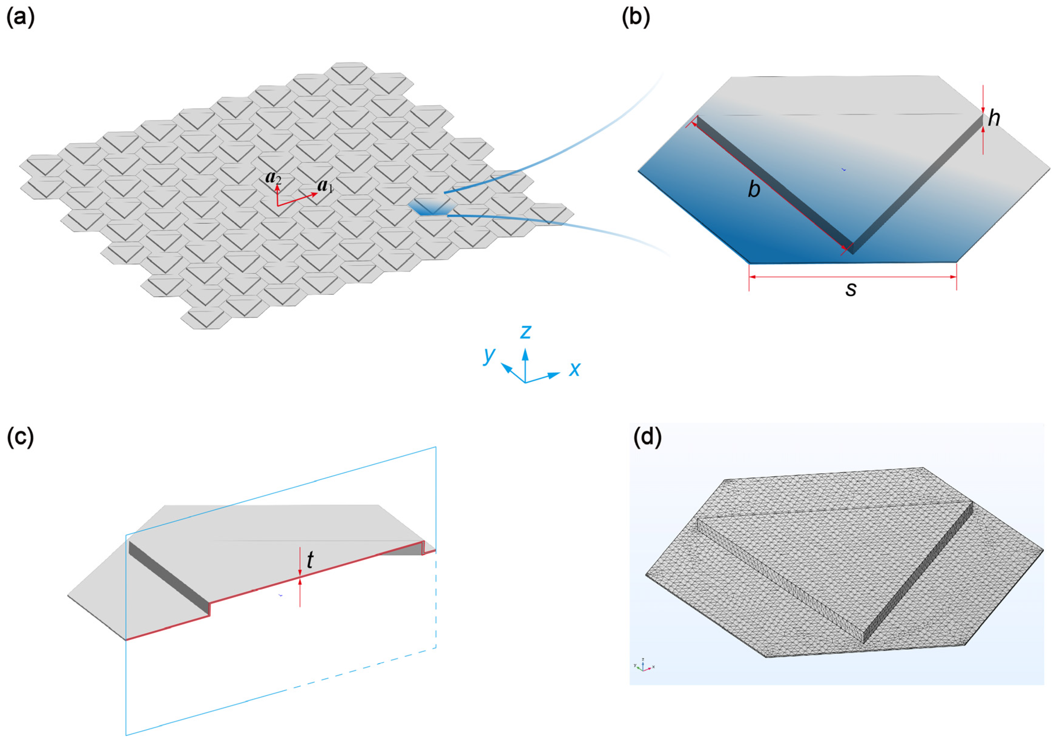
Our approach begins with the design of the unit cell. As depicted in
Figure 1, we illustrate a metamaterial plate comprised of a hexagonal lattice pattern formed by stamping triangles. The length of each hexagon is represented by
, while the unit cell lattice constant is defined as
. The stamping triangles have a length of
and a height of
. Furthermore, the plate exhibits a thickness of
and is fabricated using acrylic glass, which has a Young’s modulus
, a Poisson’s ratio
, and a mass density
. The material properties and geometry of the metamaterials plate are list in
Table 1. To obtain the phononic band structure, we solve numerically the following elastic wave equations [
36],
where
is the mass density depending on the position
,
is the displacement vector,
is the stress matrix, and
is the stiffness matrix.
In this paper, we adopt COMSOL 6.0 Multiphysics software to perform the numerical simulation. There are more than 100,000 degree-of-freedoms in one unit cell to ensure the accuracy of the results (see
Figure 1d). It is important to emphasize that the stamping triangles play a crucial role in fine-tuning the dispersion curves of the unit cell, controlling the propagation of Lamb waves throughout the metamaterial plate.
The primary advantage of this method over more traditional techniques lies in its ease of fabrication; stamping structures are already widely employed across a multitude of industries, such as in the automotive sector for reinforcing structural stiffness. By harnessing the inherent simplicity and versatility of stamping technology, the design methodology not only streamlines the manufacturing process but also presents an accessible and cost-effective alternative to current approaches. This innovation has the potential to make substantial strides in the development of practical metamaterials for various engineering applications, such as vibration isolation and noise reduction.
3. Bulk Dispersion and Topological Phase Transition
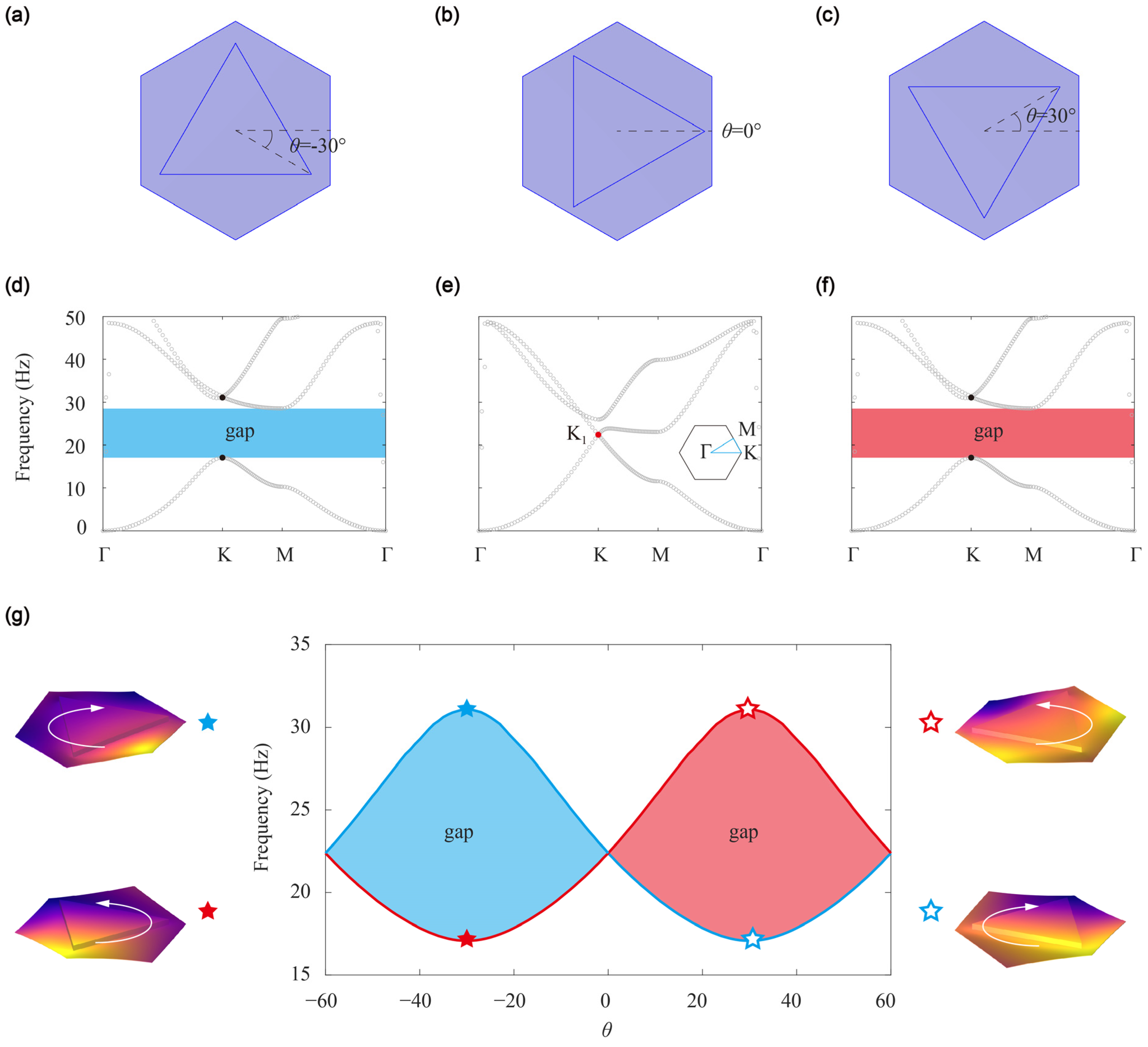
In
Figure 2, we show the dispersion curves of the unit cell at three different angles,
,
, and
. At
(
Figure 2b), the unit cell exhibits full
symmetry and, as a result, a Dirac point arises at the K point. However, at
or
(
Figure 2a,c), the
symmetry is broken, and the structure retains only
symmetry. In this case, a complete band gap ranging from
to
emerges (
Figure 2d,f). To distinguish between the stamping plates, we label the plate with
as A and the plate with
as B. It is worth noting that despite having identical dispersion curves, the topological properties of A and B are inversely related.
To describe the topological properties of the structure, we use the topological valley Chern number [
20,
33]
given by
. Here,
represents the Berry curvature of the band gap, where
denotes the Berry connection. To perform the calculations, we discretize the Brillouin zone into 50 × 50 small regions and summarize the Berry connections over each region to obtain the Berry curvature. On the other hand, the Hamiltonian of valley system can be expressed as
, in which
,
, and
are the Pauli matrices,
represents the equivalent mass,
is the Dirac velocity of the conic dispersion. The valley Chern number
[
37]. Therefore, when
,
; when
,
. It indicates that the topological constant of A and B will flip and topological edge states will emerge at the interface of AB or BA.
We further investigate the evolution of the bandgap as the rotation angle
smoothly varies from
to
. The width of the bandgap is observed to exhibit a wav and wax pattern, which leads to the opening and closing of the bandgap (
Figure 2g). To further understand the topological properties of the structure, we select two eigenmodes at the K point with rotation angles
and
. We find that the rotation directions of the two eigenmodes invert, indicating the inversion properties of the topological bandgap. This observation suggests that the topological valley Chern number,
, changes sign under the rotation of the stamping plate. Therefore, the valley Hall effect could be realized by using a device based on this structure.
4. Low-Frequency-Vibration Isolation in Helicopters
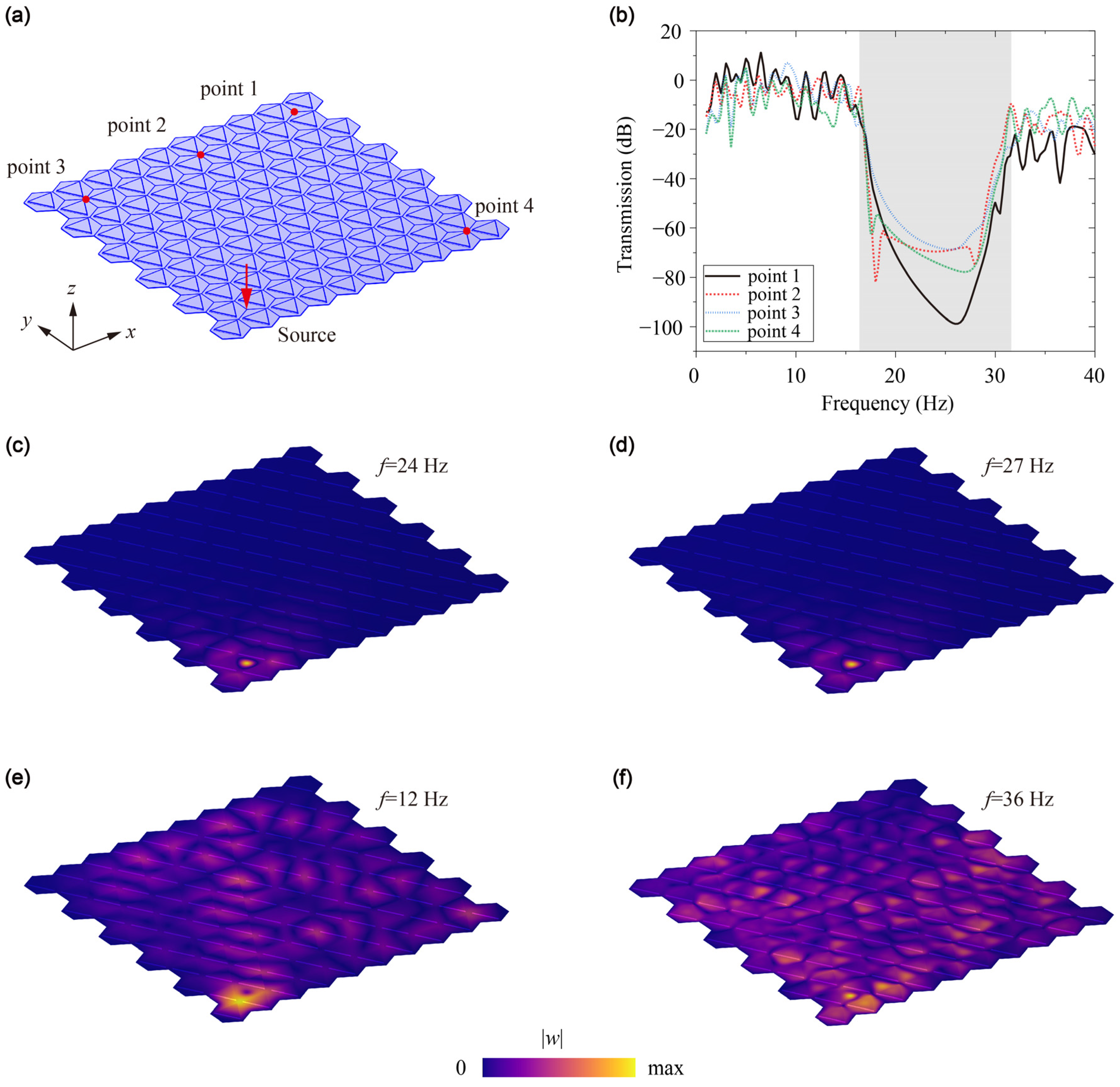
Before examining the topological wave guiding properties of the stamping metamaterial plate, it is essential to confirm its ability to isolate low-frequency vibrations effectively. As depicted in
Figure 3a, we have modeled a finite metamaterial plate consisting of 114 unit-cells, while configuring the boundaries of the structure to maintain low-reflecting conditions. To simulate excitation, a point source with a unitary displacement (1 mm) in the
z direction is applied to one corner of the system, generating vibrations throughout the plate.
To assess the plate’s response to the excitation at various frequencies, we employ four detection points positioned to represent different propagating directions. The frequency range of the excitation spans from
to
, incremented in steps of 0.5 Hz. The transmission is defined by
, where
and
are the detection and source applied at the metamaterial plate.
Figure 3b presents the transmission obtained from this series of experiments. Upon analyzing the results, we identify a low transmission region which precisely aligns with the frequency range of the bandgap in the metamaterial plate. This observation implies that when the excitation frequency falls within the bandgap range, the stamping metamaterial plate effectively isolates vibrations at low frequencies. Consequently, this feature of the metamaterial plate becomes a crucial factor in understanding its topological wave guiding properties and its potential for application in various vibration-sensitive contexts.
To provide a more comprehensive assessment of the vibration isolation capabilities of the stamping metamaterial plate, we examine the displacement distribution across the plate at varying frequencies, specifically at
,
,
, and
. The displacement distributions are illustrated in
Figure 3c–f. When the excitation frequencies that reside within the bandgap, such as
and
, we observe that the vibration energy remains localized in close proximity to the source and is unable to propagate throughout other areas of the structure. This highlights the plate’s effectiveness in reducing vibrational energy transmission. Conversely, when analyzing frequencies that fall outside the bandgap, such as
and
, we find that the disturbance is no longer confined near the source and instead diffuses across the entire structure.
Based on these observations, we can conclusively affirm that the stamping metamaterial plate demonstrates exceptional potential as a platform for vibration isolation. By effectively limiting the transmission and amplitude of vibrations, especially within the bandgap frequency range, the plate offers valuable application possibilities for the mitigation of undesired vibrations in a myriad of settings, promoting increased efficiency and reliability in various systems and environments.
5. Emergence of Topological Edge States
Beyond its excellent vibration isolation properties, the stamping metamaterial plate exhibits a notable phenomenon known as the topological valley Hall effect, which results in the existence of edge states at the plate interfaces to control elastic waves. This effect arises from the valley degree of freedom present in the plate’s phononic band structure. In particular, it involves a topological nontrivial phase that leads to robust edge states at the boundary of the system.
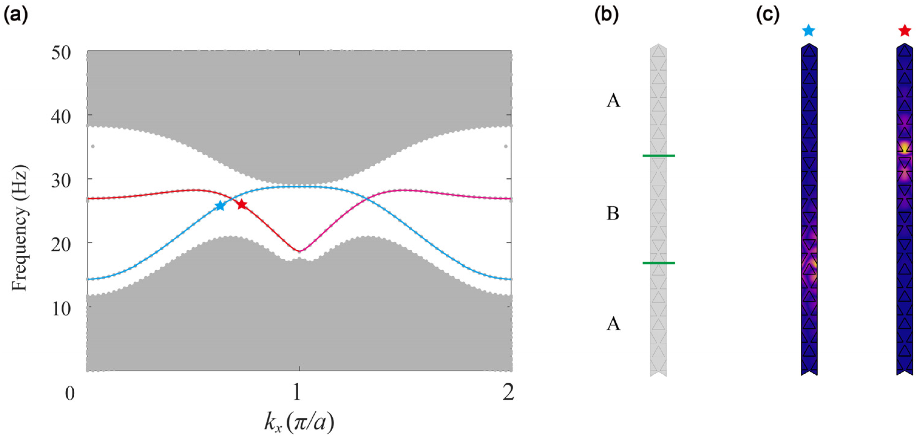
To illustrate this effect, we construct a supercell consisting of 24 unit-cells arranged in an A–B–A form. This supercell is finite in the
direction and periodic in the
direction. We plot the projected dispersion of this supercell in
Figure 4a, which reveals a pair of edge states connecting the upper and lower boundaries of the bandgap. The bulk dispersions, represented by the gray regions, exhibit a bandgap around the high symmetry point
, where the edge states occur. On the other hand, the red and green lines depict the edge states at the A–B and B–A interfaces, respectively.
An important feature of these topological edge states is their robustness against backscattering. As a result, elastic waves can propagate unobstructed along the interfaces, behaving similar to a robust waveguide. In other words, these edge states have the capability of localizing acoustic energy along the interface without any significant loss, making them a promising technology for advanced elastic waveguides and other such applications. The reason for the robustness of the topological edge states in the stamping metamaterial plate lies in the relatively large distance between the two valleys
and
in the momentum space. This leads to less coupling between the two states, as reported in previous studies [
30,
31,
32,
33]. Moreover, the difference between the two types of edge states—at the A–B and B–A interfaces—arises from the distinct pattern of stamping triangles at these interfaces, as shown in
Figure 4b. The eigenmodes corresponding to the stars in
Figure 4a, which exhibit localized energy at the A–B and B–A interfaces, are depicted in
Figure 4c. This figure illustrates the distinct patterns of oscillation between the two types of edge states and further highlights their unique characteristics.
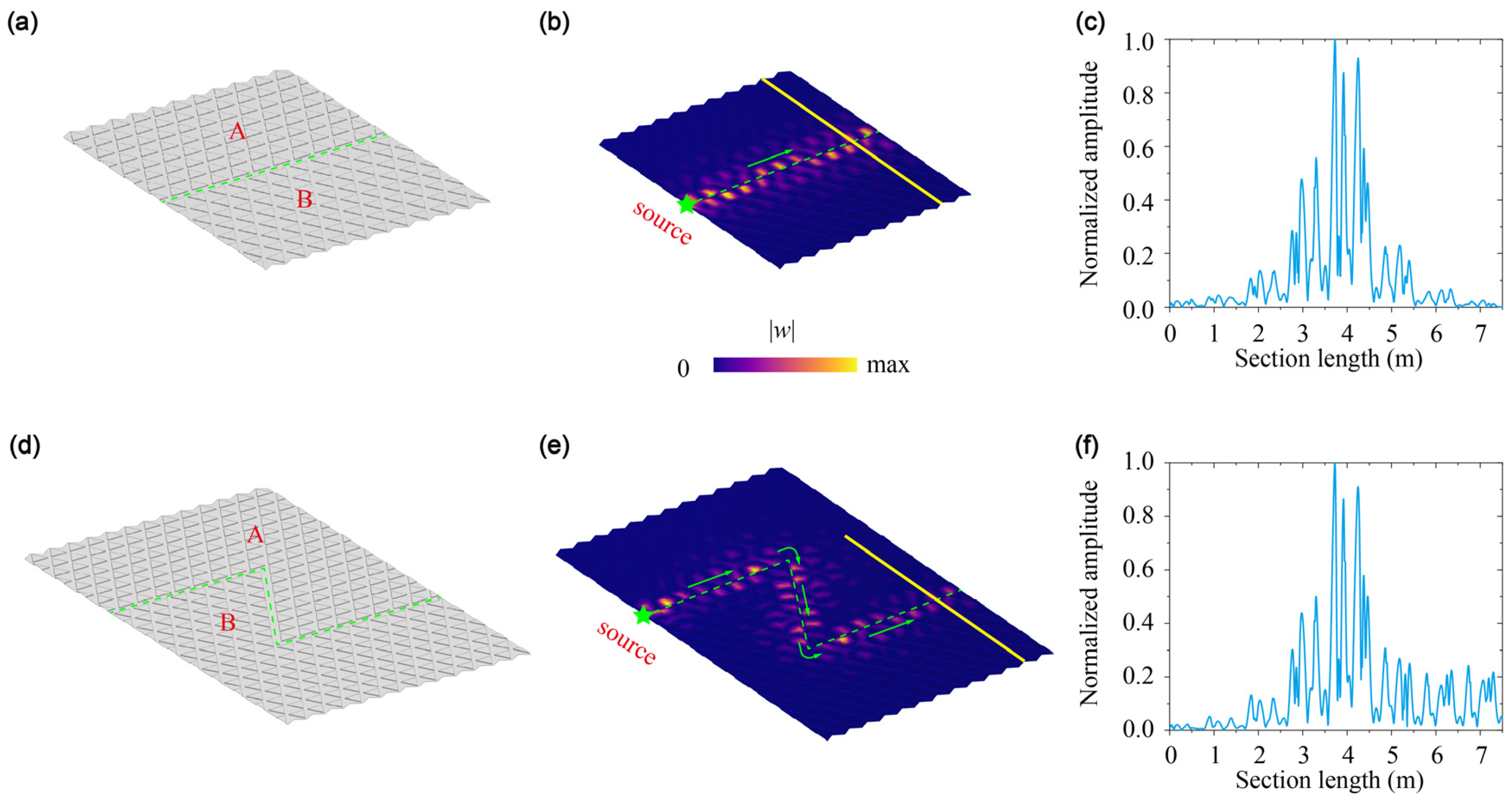
6. Robust One-Way Wave Manipulation
Finally, we investigate the wave propagation along both straight and Z-shaped A–B interfaces. In the case of the straight interface, we consider a finite structure consisting of 160 unit-cells and applied a point source at the left end of the interface. To prevent reflections, all the boundaries are set to be absorbing. The excitation frequency is chosen to be
and the displacement field of
in the sample is shown in
Figure 5b. As observed, the energy is strongly localized at the A–B interface. To gain a deeper understanding of this behavior, we present the displacement distribution of the cross-section on the right end of the sample (marked by the yellow line in
Figure 5b) in
Figure 5c. This reveals that the energy is highest at the center and lower on both sides, clearly indicating the localization of the wave. These results underscore the remarkable ability of the topological edge states to confine acoustic energy along the interface, making them an excellent candidate for various acoustic waveguide applications.
We then construct a Z-shaped waveguide that contained two sharp corners, as shown in
Figure 5d. In a conventional waveguide, the energy propagating along the interface suffers backscattering when it reaches corners due to the impedance mismatch; however, topological waveguides exhibit the remarkable ability to bypass corners and maintain robust one-way wave propagation. To verify this property, we apply a point source at one end of the Z-shaped waveguide and use a frequency of 24 Hz. The resulting displacement field of
is shown in
Figure 5e, where we observe that energy can propagate along the interface without significant backscattering. Furthermore, the displacement distribution along the cross-section indicates localization of the wave at the interface, thus confirming the robustness of topological edge states.
These results demonstrate that the stamping metamaterial plate can be used to manipulation elastic wave propagation for various applications in the field. By utilizing the unique properties of topological waveguides, we may overcome limitations and expand the possibilities of wave manipulation.
7. Conclusions
Stamping is a well-established engineering process that is easy to work with, and its products and structures have found broad applications in various mechanical systems. Stamping processes can create features such as protrusions or depressions that significantly improve a structure’s support stiffness and reduce deformation. In terms of dynamics, stamping shapes can effectively modulate bending vibration and wave, suppress specific frequency vibration, and control the propagation of elastic waves. We focus on the 24 Hz resonance frequency generated by helicopters due to the multiplicative frequency of their propellers during operation. To address this unfavorable vibration, we designed a metamaterial plate structure using the stamping process. The structure features stamped triangles arranged in a specific pattern that helps manipulate the propagation of elastic waves and reduce bending vibration and wave. This innovative approach successfully mitigates the negative effects of the 24 Hz resonance frequency on helicopters during operation.
In conclusion, we have successfully designed a metamaterial plate with stamping triangles based on the topological valley hall effect. By manipulating the stamping triangle orientation, we were able to tune the bandgap to be either closed or opened. When we set , the bandgap covered the typical frequency range of in helicopters. Our results demonstrate that the stamping metamaterial plate exhibits excellent vibration isolation under excitation, revealing its practical potential for a wide range of applications. In addition, we constructed interfaces with opposite valley Chern numbers at and and illustrated the topological edge states at the interfaces. Moreover, we conducted demonstrations of the robust wave propagation phenomena along line and Z-shaped topological waveguides, revealing the exceptional wave control capabilities of the stamping metamaterial plate.
Our study contributes to the advancement of topological metamaterials designed for vibration isolation and wave control in helicopters, using stamping technology. This research paves the way for a new fabrication of unique metamaterials, with potential applications in acoustic and elastic wave manipulation. The adoption of stamping technology offers cost-effective production, enabling broader use across various industries and revolutionizing noise and vibration attenuation in aerospace engineering.


