Article

Optimizing Energy and Reserve Minimization in a Sustainable Microgrid with Electric Vehicle Integration: Dynamic and Adjustable Manta Ray Foraging Algorithm

1
College of Engineering, University of Kirkuk, Kirkuk 36001, Iraq
2
Department of Petroleum Engineering, Al-Kitab University, Altun Kupri 36001, Iraq
3
Mechanical Engineering Department, College of Engineering, Gulf University, Sanad P.O. Box 26489, Bahrain
4
School of Artificial Intelligence, Nanchang Institute of Science and Technology, Nanchang 330099, China
5
Mechanical and Automotive Engineering Technology, Universiti Malaysia Pahang, Pekan 26600, Malaysia
6
Department of Electrical and Electronics Engineering, University of Gaziantep, 27310 Gaziantep, Turkey
*
Author to whom correspondence should be addressed.
Processes 2023, 11(10), 2848; https://doi.org/10.3390/pr11102848
Submission received: 9 July 2023 / Revised: 9 August 2023 / Accepted: 15 August 2023 / Published: 27 September 2023
(This article belongs to the Special Issue Clean and Efficient Technology in Energy and the Environment)

Abstract

:
The growing presence of EVs in regional microgrids introduces increased variability and uncertainty in the areas’ load profiles. This paper presents a novel approach for optimizing energy and reserve minimization in a sustainable integrated microgrid with electric vehicles (EVs) by the use of the dynamic and adjustable Manta Ray Foraging (DAMRF) algorithm. The DAMRF algorithm harnesses the inherent flexibility of EVs as controllable loads and develops a comprehensive dispatch model for a large-scale EV response. The model takes into account the management, operational, and environmental costs associated with load fluctuations in the microgrid. Simulation evaluations conducted based on a practical microgrid environment validate the effectiveness of our wind–solar energy storage and management strategy. The results showcase significant improvements in energy and reserve minimization, highlighting the potential advantages of integrating EVs into sustainable microgrid systems. In addition, the DAMRF algorithm achieves lower environmental pollution control costs (USD 8000) compared to the costs associated with the Genetic Algorithm (GA) (USD 8654.639) and PSO (USD 8579.546), emphasizing its ability to effectively control and minimize environmental pollution. In addition, the DAMRF algorithm offers a more cost-effective solution for managing the power grid, and the shorter solution running time of the DAMRF is almost the same as PSO’s quicker decision-making and response times, enhancing the overall responsiveness and adaptability of the power grid management system.

1. Introduction

Efficiently optimizing the economic dispatch and operation of microgrids is a multifaceted challenge, necessitating careful consideration of each microgrid’s unique characteristics and needs when selecting the most suitable control method. The unpredictable and fluctuating nature of EV charging and discharging patterns presents unique challenges, requiring customized solutions to ensure the smooth integration and optimal utilization of EVs within microgrid operations. As a result, various issues have arisen, such as capacity limitations within the station area, overloading of distribution transformers, heightened losses in transmission lines and transformers, and other related concerns. Addressing these challenges is crucial to achieving a harmonious and efficient coexistence of EVs and microgrids. Simultaneously, dynamic energy power generation systems have emerged in various countries, presenting an opportunity to effectively utilize the installed energy generation capacity, promote energy conservation, and facilitate sustainable energy development [1,2]. Notably, remarkable advancements have been made in power grid technology, particularly in the electric vehicle industry, with the rapid progress of vehicle-to-grid (V2G) technology [3,4]. This technology enables the interaction between electric vehicles and the grid, opening up possibilities for economic optimization management that actively involves both EVs and large-scale electric vehicle charging stations.
The economic dispatch of microgrids, particularly involving the participation of electric vehicles (EVs) and other power generation equipment, has become a focal point of research in the field of microgrid control. Numerous control methods have been introduced to optimize the economic dispatch and operation of microgrids, drawing considerable attention from researchers [5,6,7,8,9,10,11,12,13,14]. In [5], the authors describe a study that used the temporal and spatial properties of electric vehicles to create a model for orderly charging and discharging that took into account current electricity pricing. To examine the tactical coordination between EV power stations and microgrids, another research project built a microgrid economic dispatch optimization model [6]. The effective utilization of electric vehicles for optimizing charging and reducing system load peaks and valleys was demonstrated [7]. Nevertheless, certain research works have neglected the economic considerations, as well as the safety and performance aspects, of microgrid management and the active involvement of EV users [1,8]. In response, a comprehensive analysis has been conducted to optimize the integration of electric vehicles (EVs) in microgrid operation and management [9,10]. Furthermore, reference [11] investigates the annual operation and benefits of EVs and vehicle-to-grid (V2G) systems within a microgrid context, illustrating diverse operational modes based on present and projected EV technological trends. Ref. [12], a genetic algorithm is suggested to optimize the size of an island-mode microgrid while taking many objectives into account. Finding the ideal configuration that strikes a balance between many aspects is the goal. Ref. [13] focuses on minimizing environmental pollutants when optimizing microgrid operation. The microgrid consists of load-responsive storage systems and renewable energy sources (RESs). While meeting the energy demand, the environmental impact must be kept to a minimum. Ref. [14] investigates a microgrid’s schedule optimization with the aim of maximizing its profit. The ideal operating schedule is determined by taking into account many elements like energy generation, storage, and load demand.
Electric vehicle (EV) technology adoption in microgrids has drawn interest recently because of its potential to increase flexibility and decrease environmental pollutants [15]. The design, installation, and operation of microgrids, Vehicle-to-grid (V2G) technology, and paralleling sources to the grid can benefit significantly from adhering to established industrial standards. These standards ensure a consistent and reliable approach across different implementations, promoting a safer, more efficient, and interconnected energy ecosystem. The need for additional research about and application of plug-in hybrid electric vehicles (PHEVs) in microgrids has been emphasized in environmental reports showing the detrimental effects of fossil-fuel-based automobiles globally [16]. However, since PHEVs are so important to the growth of this transportation system, the problem is in designing high-capacity, low-cost batteries for PHEVs. It is possible to lower operating costs by integrating PHEVs into microgrids [17]. Utilizing the PHEVs’ energy storage capabilities allows for the optimization of a microgrid’s overall energy management and cost effectiveness by storing excess energy during times of low demand and discharging it during times of peak demand. Ref. [18] focused on developing microgrid operation control algorithms for grid-connected and isolated island modes as well as various EV access modes, with optimal energy scheduling taking EV charging loads into account. In terms of solar and wind energy integration, research has focused on optimizing battery energy storage control strategies while considering the memory effect of batteries, as well as exploring operational energy management strategies for isolated microgrid systems with hybrid energy storage [19]. Ref. [20] highlights the integration of second-order differentiators and a rule-based energy management strategy to achieve robust control. The use of voltage/current references obtained through the energy management strategy contributes to enhancing control performance. Ref. [21] addresses multiple uncertainties commonly found in microgrids, such as limited photovoltaic generation, fluctuating market prices, and the need to control various loads. These uncertainties pose significant challenges in managing campus energy with multiple microgrid systems, making it a critical area of research in the current era. Ref. [22] demonstrates the effectiveness of the proposed trajectory optimization method in reducing energy consumption and further validates the significance of the research. Investigating the effects of the trajectory on energy consumption adds depth to the findings and contributes to a better understanding of the overall energy-saving potential. Ref. [22]’s introduction of a fuzzy decision-making method further enhances the usefulness of the proposed algorithm. Thus, decision-makers can use this method to obtain a solution from the Pareto front that optimally balances the different objectives, providing valuable insights into the trade-offs between various aspects of the hybrid microgrid systems design. However, the existing energy management strategies discussed in the aforementioned studies do not fully address the requirements of smart stations and economic dispatch models. Therefore, it is important to effectively manage the microgrid’s load fluctuations, taking into account management, operational, and environmental costs associated with the presence of EVs, wind–solar energy storage, and overall power grid management.
This paper introduces a novel smart energy management strategy focused on minimizing the overall cost associated with energy generation within a specified time frame. The proposed approach incorporates a Microgrid Scheduling model specifically designed for large-scale electric vehicles (EVs). The primary objective is to optimize the storage output to achieve the lowest possible cost by considering three key factors: operation cost (OC), load fluctuation, and environmental pollution penalties. To address this optimization problem, the DAMRF algorithm is employed, drawing inspiration from the foraging behavior of manta rays. By combining movement, adaptation, and search mechanisms, the DAMRF algorithm effectively explores the solution space and provides optimized solutions for energy and reserve minimization in sustainable microgrid systems with EV integration. To achieve the desired optimization, an optimal controller is developed to identify the storage output that minimizes the total cost. The implementation of this smart energy management strategy is expected to yield significant cost savings in energy generation and utilization. This approach contributes to enhancing the overall efficiency and sustainability of the system, aligning with the goals of cost reduction and environmental impact mitigation.

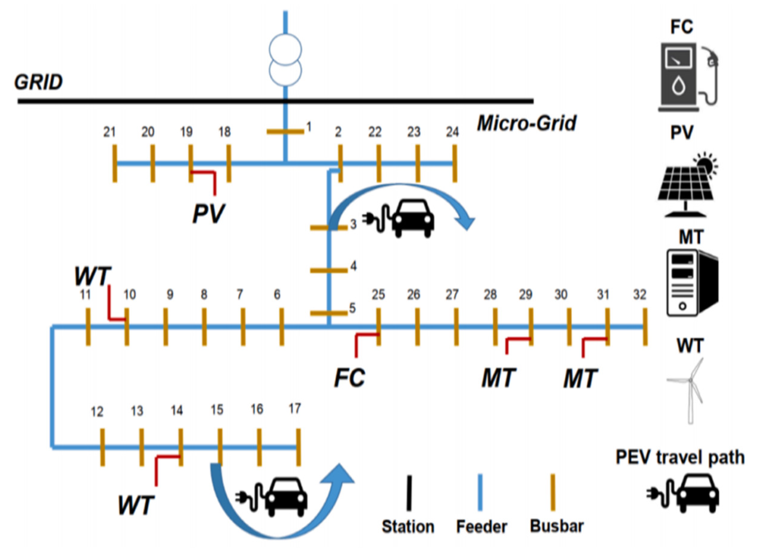
2. Microgrid Scheduling Model of Large-Scale EVs

Within the regional microgrid, it has been observed that certain electric vehicle (EV) users actively respond to the dispatching information provided by the microgrid management center [23,24,25,26]. These responsive users willingly adjust their charging and discharging activities in accordance with the directives given by the microgrid. Conversely, there are also users who do not adhere to the dispatching information and instead opt for a random charging approach [27]. In Figure 1, a visual representation of the dispatching structure within a microgrid, focusing on the interaction between the microgrid management center and electric vehicle (EV) users. The diagram highlights the configuration and interconnection of the dispatching system, showcasing the components crucial to managing the regional response of EVs within the microgrid. This system plays a vital role in achieving efficient energy utilization and grid stability. The sub-system parameters and their impact on the entire microgrid are shown.
Wind turbine: Its effectiveness is influenced by various factors, such as wind speed, wind direction, and the turbine’s capacity. The variability of wind energy can lead to fluctuations in the microgrid’s power generation, which needs to be effectively managed to maintain grid stability.
The photovoltaic (PV) panel: Its performance depends on solar irradiance, temperature, and the panel’s efficiency. Solar energy can be intermittent, which means the microgrid’s power supply will be subject to fluctuations based on weather conditions and time of day.
Plug-in hybrid electric vehicle (PHEV): It can be charged from the grid and have both an internal combustion engine and an electric motor. These vehicles can operate in electric-only mode, drawing power from the microgrid, or use their internal combustion engines. The charging and discharging characteristics of PHEVs are essential to understand for effective dispatching, as they can provide energy to the grid or draw energy from it.
The charging power of EV users is as follows:
C h a r g i n g t = i C i t . P c h a r g e t
where C i t is the charging coefficient of EV user i, which indicates the willingness and ability of the user to charge their EV; P c h a r g e t is the charging power of EVs.
Similarly, the discharging power of EV users can be calculated as:
D i s c h a r g i n g t = j D j t . P d i s c h a r g e t
where D j t is the discharging coefficient of EV user j at time t, which signifies the user’s willingness and ability to discharge power from their EV; P d i s c h a r g e t is the discharging power of EVs.
The EV’s disorderly charging model captures the scenario wherein some EV users in the area engage in uncoordinated or random charging behavior, without responding to any specific dispatching information from the microgrid management center. The disorderly charging model captures the uncoordinated behavior of EV users, wherein each EV user independently decides whether to charge based on their own internal factors or random factors. This model provides insights into the charging patterns and potential impact of uncoordinated charging on the microgrid’s overall operation and management.
We characterize the charging patterns and behaviors of these EV users. In the disorderly charging model, the charging power of each EV is determined independently and randomly. The disorderly charging behavior of EVs can be mathematically described as follows:
P c h a r g e , m a x t ( i ) w i t h   p r o b a b i l i t y   p i t 0 , w i t h   p r o b a b i l i t y   1 p i t
where P c h a r g e , m a x t (i) represents the maximum charging power that E V i can draw at time t. The probability p i t determines whether the E V i chooses to charge or not at time t. If p i t is high, the EV is more likely to charge, and if p i t is low, the EV is less likely to be charged.
The user response scheduling charge and discharge model is designed to capture the behavior of electric vehicle (EV) users who actively respond to the dispatching information from the microgrid management center, engaging in coordinated charging and discharging activities.
The user response scheduling charge and discharge model considers the total charge and discharge power during both peak time and off time in the microgrid. The total charge power during peak time at time t is denoted as P c h a r g e P e a k t , and the total discharge power during peak time is denoted as P d i s c h a r g e P e a k t . Similarly, the total charge power during off time is denoted as P c h a r g e O f f t , and the total discharge power during off time is denoted as P d i s c h a r g e O f f t .
The total charge power during peak time at time t can be calculated as the sum of the charging powers of all EV users during peak hours:
P c h a r g e P e a k t = i = 1 N P c h a r g e t ( i ) . I p e a k t ( i )
where P c h a r g e t ( i ) represents the charging power of EV user i at time t, and I p e a k t ( i ) is an indicator function that determines whether the time t falls within the peak hours for EV user i.
Similarly, the total discharge power during peak time at time t can be calculated as the sum of the discharging powers of all EV users during peak hours:
P d i s c h a r g e P e a k t = i = 1 N P d i s c h a r g e t ( i ) . I p e a k t ( i )
The total charge power during off time at time t can be calculated as the sum of the charging powers of all EV users during non-peak hours:
P c h a r g e O f f t = i = 1 N P c h a r g e t ( i ) . ( 1 I p e a k t ( i ) )
By considering the total charge and discharge power during peak time and off time, the user response scheduling charge and discharge model allows for the effective management and coordination of EV charging and discharging activities based on the system’s load requirements and peak demand periods. The total discharge power during off time at time t can be calculated as the sum of the discharging powers of all EV users during non-peak hours:
P d i s c h a r g e O f f t = i = 1 N P d i s s c h a r g e t ( i ) . ( 1 I p e a k t ( i ) )

3. Proposed Method

3.1. Problem Formulation

Problem formulation represents the total cost of managing, running, and protecting the environment for the regional microgrid, which includes all expenses related to its operation.
m i n F = λ 1 ( F 1 + F 2 ) + λ 2 F 3
where λ 1 and λ 2 are weighting factors, where λ 1 + λ 2 = 1 .
The objective function for the microgrid’s OC and the incentive cost (IC) for EVs actively participating in grid operation and reacting to dispatch:
F 1 = t = 1 t n n = 1 n C n G n t + M n P n + I ( E t + S t + )
where: Mn is cost of the maintenance; Pn is output of the power generation at time t; Cn is cost of the power generation; I is the cost of incentive EVs; Et+ represents the electricity purchased by the microgrid management center from users at time t; St+ represents the electricity sold by the microgrid management center to EVs at time t.
To get EVs to respond to dispatching information and utilize the capacity of their EV power batteries, the regional microgrid control center uses incentives. These incentives aimed at attracting EV owners to charge or discharge their vehicles in alignment with the microgrids can be calculated using the following expression:
F 2 = t = 1 t n [ N ( P h o m t P t + ) ( Δ t h o m t + Δ t t + ) ]
where Δthomt and Δtt+ are the continuous time required for EV users to discharge and charge to the regional microgrid, respectively; Pt+ is the charging price for the user; Phomt is the on-grid price at time t; and N is the total number of EVs.
The cost calculation considers the pollutant penalty associated with the emission of NOx, SO2, and carbon during the power generation process. The pollutant penalty costs associated with microgrid operation can be calculated as:
F 3 = m = 1 M [ C m × ( E n + E t + ) × P t + ]
where Cm is the pollutant cost per kilogram; and En+ is the emission coefficient.

3.2. Constraints

The constraints related to the economic OC of the microgrid, the IC for EVs, and the pollutant penalty costs can be formulated as follows:
Economic OC: The constraint of the microgrid should be minimized and should not exceed a certain threshold:
n ( C n × P n ) + C i n c e n t i v e C m a x
where C i n c e n t i v e is the total IC for EVs, and C m a x is the maximum allowable economic OC.
The IC constraint for EVs should not exceed a certain limit:
C i n c e n t i v e C i n c e n t i v e m a x
where C i n c e n t i v e m a x is the maximum allowable IC for EVs.
The pollutant penalty cost constraint for microgrid operation should not exceed a certain threshold:
m ( E n m × C m × P n ) + E grid m × C m × P g r i d C p e n a l t y _ m a x
where Enm is the emission coefficient, E grid m is the emission coefficient from the grid, P g r i d is the power imported from the grid, and C p e n a l t y _ m a x is the maximum allowable pollutant.

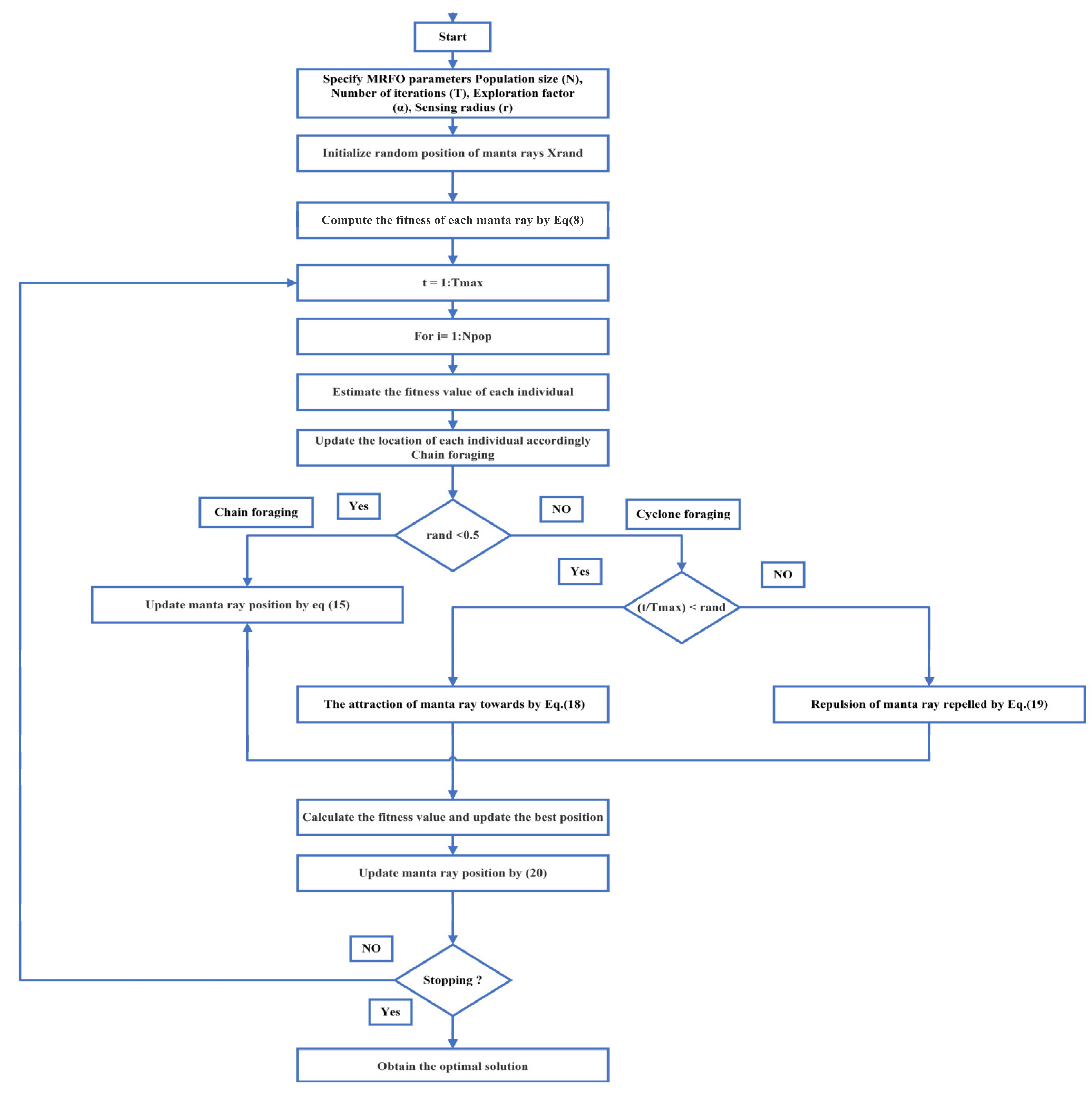
3.3. Dynamic and Adjustable Manta Ray Foraging (DAMRF) Algorithm

The DAMRF algorithm utilizes a population of virtual manta rays, each representing a potential solution to the optimization problem. These virtual manta rays move and interact in the search space to find the optimal solution. The algorithm is dynamic and adjustable, meaning that it adapts and adjusts its search behavior based on the problem characteristics and current search progress. The manta ray agents explore the solution space by adjusting their positions. They mimic the foraging behavior of manta rays, which involves searching for food sources in the ocean. The movement of agents is guided by mathematical equations that control their velocity and direction. The algorithm incorporates adaptive mechanisms to dynamically adjust parameters and adapt to changing conditions. This allows the manta ray agents to respond to variations in load profiles, energy availability, and system constraints. The DAMRF algorithm utilizes the following key steps to guide the movement and behavior of manta rays, as illustrated in Figure 2:
1. A fitness evaluation is performed: each manta ray’s fitness value is evaluated using the objective function and any applicable constraints of the optimization problem.
2. The position of a manta ray is updated based on its current position, the positions of other manta rays, and the movement step size:
NewPosition ( t + 1 ) = CurrentPosition ( t ) + δ × MovementDirection ( t )
3. The movement direction of a manta ray at iteration t is calculated as a weighted sum of three components: random exploration, attraction towards the best position, and repulsion from nearby manta rays:
MovementDirection ( t ) = α × RandomExploration ( t ) + ( 1 α ) × Attraction ( t ) Repulsion ( t )
4. A random exploration vector is generated to introduce exploration and randomness in the movement:
RandomExploration(t) = RandomVector()
5. The attraction of a manta ray towards the best position found so far, which promotes the exploitation of promising regions, is calculated:
Attraction ( t ) = β × ( BestPosition CurrentPosition ( t ) )
6. The repulsion of a manta ray repelled from nearby manta rays within its sensing radius, preventing crowding and encouraging diversity, is calculated:
Repulsion ( t ) = γ × Σ [ RepulsionForce ( i ) ]
7. The repulsion force between two manta rays is determined based on their positions and a repulsion factor:
Repul . Force ( i ) = Repul . Factor × (CurrentPosition ( t ) Position ( i ) ) / Distance ( CurrentPosition ( t ) , Position ( i ) )
where population size (N) is the number of manta rays in the population, representing potential solutions; the number of iterations (T) is the maximum number of iterations or generations that the algorithm will run; the exploration factor (α) is a parameter that controls the balance between exploration and exploitation during the movement and foraging behavior; the sensing radius (r) is the maximum distance within which a manta ray can sense and interact with other manta rays in the population; the movement step size (δ) is the distance that a manta ray can move in each iteration, influencing its exploration and exploitation capabilities.

4. Simulation Results

4.1. Simulation Parameters Setting

In this study, a 12.66 kV test system was examined using a simulated model. As shown in Figure 3, the system has 32 nodes and functions in a grid-tied mode. Two wind turbines (WTs), one solar PV, two Micro-Turbines (MTs), and one fuel cell (FC) are among the generating units used in the test system. Additionally, as indicated in Figure 4, two fleets of plug-in electric vehicles (EVs) are integrated into the system. The power output of renewable energy sources (RESs), market prices, load demand, the arrival and departure timings of EVs, and the size of each EV fleet are some of the aspects of the problem that can be uncertain. The following table shows how different distributed generation (DG) units are spread: a photovoltaic (PV) system is established at bus 19, an FC unit is positioned at bus 25, and WT and MT units are situated at buses 10 and 14, respectively. Two EV fleets are assigned to buses 3 and 15 in order to accommodate the utilization of locations outside of the test system under consideration. Figure 3 displays the distribution of consumers linked to each system node, illustrating the connectivity and load allocation within the network. On the other hand, Table 1 presents comprehensive statistics related to the generating units, offering essential details and performance metrics of these power generation sources [28,29]. Figure 5 illustrates the predicted power output levels for the renewable energy sources (RESs) and market prices, while Figure 4 depicts the load curve of the system. Notably, WT 2 has a capacity 1.2 times greater than WT 1 within the system. The assessment of electric vehicles’ (EVs) impact on the microgrid (MG) takes into account two fleets with distinct trip patterns. Both fleets consume the same amount of energy for their outbound and return trips. The first fleet departs from the MG, embarking on its main journey from home to work in the morning. Subsequently, the EVs from this fleet return to the MG on their second journey, which originates from the workplace late at night. This intricate analysis of EV behavior and their integration into the microgrid aids in understanding their influence on the overall system dynamics and energy usage patterns.
The second fleet begins its initial journey in the morning from a site outside the investigated network to a location inside the system. On its subsequent evening cruise, this armada leaves the system. It is important to note that because the grid is so small, excursions outside the network are taken into account. Different assessments are made of the EV fleets’ energy needs. Each EV fleet is estimated to cover about 12,000 miles annually. Each EV also has a daily energy need of 9.3 kWh and averages 3.66 miles per kilowatt-hour (kWh). Therefore, 7.62 kWh and 9.3 kWh of energy are required for each fleet at each interval. The lithium-ion (Li-ion) battery was selected for this study due to its allure and effectiveness. The Li-ion battery employed in this investigation has Whöler curve characteristics with a = 1331 and b = −1.825. With a temporal resolution of one hour, the system operates at its best throughout the course of one day. The amount of power to be imported or exported from the main grid is decided by the Microgrid Central Controller (MGCC). When the microgrid’s load demand is low, the grid can obtain the necessary electricity from the WT and PV units.

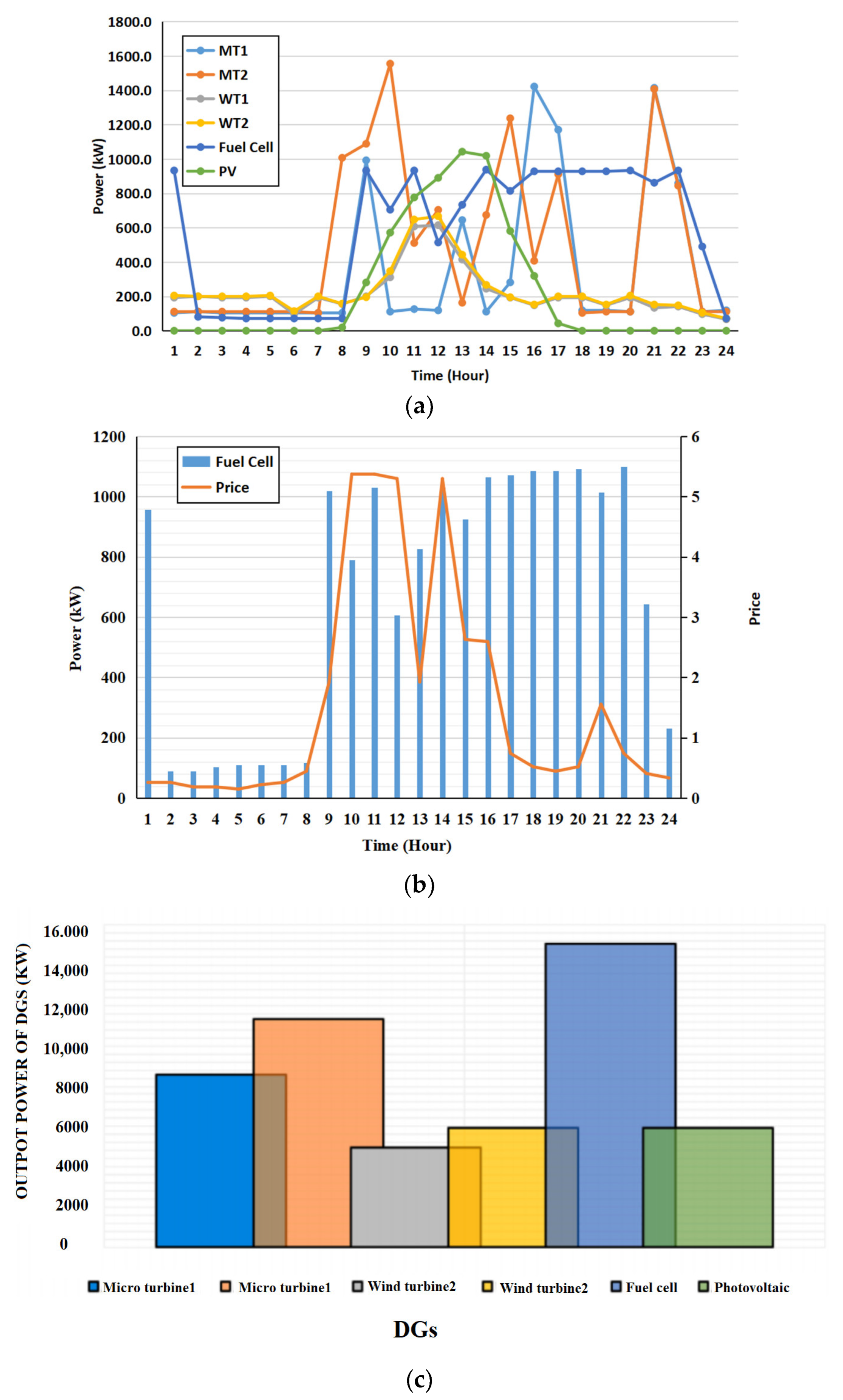
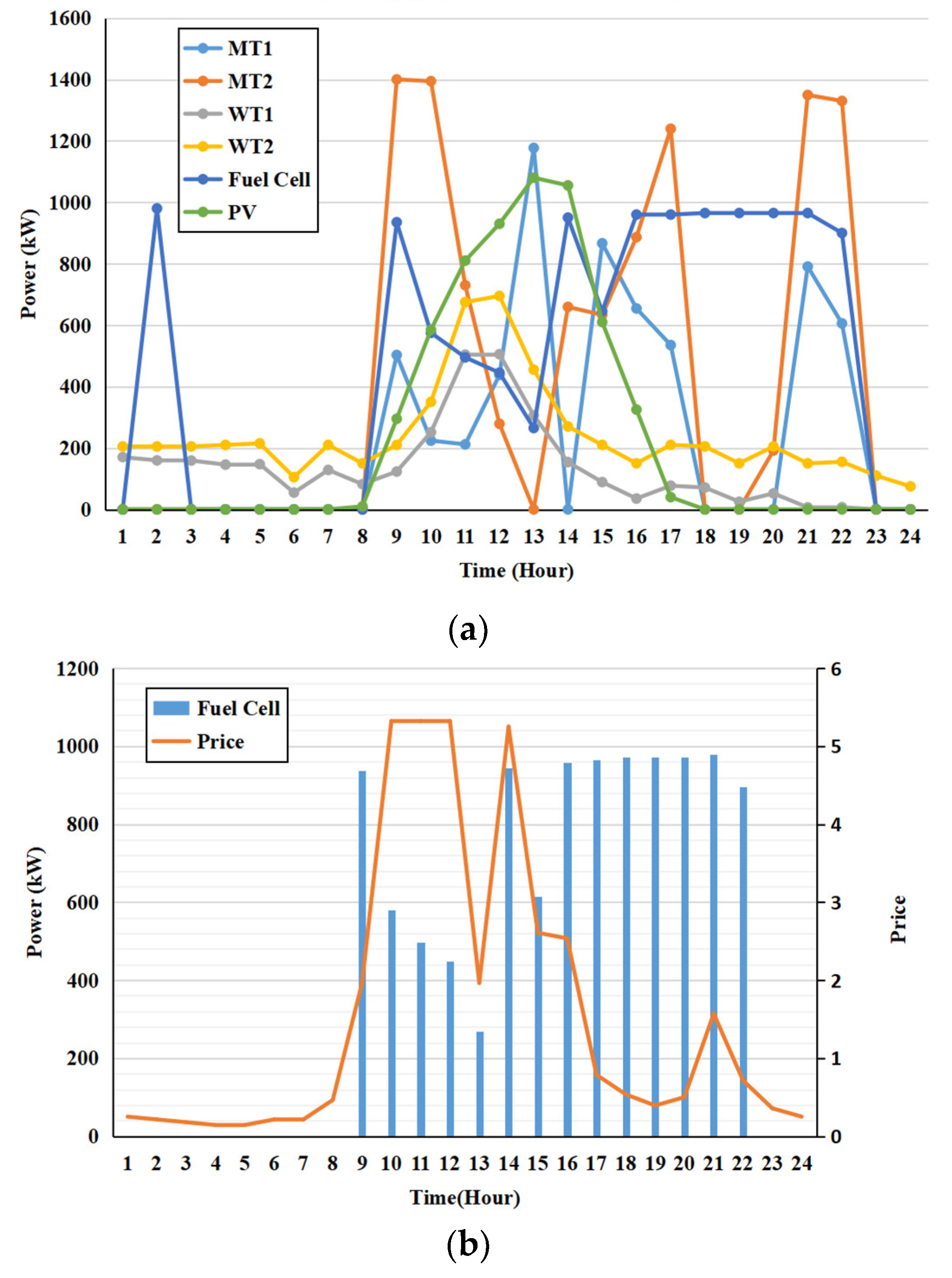
4.2. Effectiveness of Proposed Model

To study the behavior of the suggested model, three cases are taken into consideration. In the simulation, the Manta Ray Foraging (MRF) approach utilizes the following dynamic and adjustable values: population size (N): 10; number of iterations (T): 100; exploration factor (α): ranging from 0.1 to 0.5; sensing radius (r): ranging from 10 to 50.
Case 1: In this case, all units are taken to be committed, and the goal is to schedule microgrid (MG) assets as efficiently as possible without including plug-in electric vehicles (EVs). The provided methodology is statistically analyzed as shown in Table 2 along with a thorough comparison to other approaches, taking into account the best solution (BS), worst solution (WS), mean value, and standard deviation (std). This robust evaluation is essential for informed decision-making, guiding the selection of the most suitable approach for specific tasks or problems. Moreover, it provides a basis for further improvements and refinements to enhance the methodology’s performance and applicability in real-world situations. Furthermore, Figure 6a presents the optimal hourly schedule for various assets, taking into account the predefined limit of 20 iterations for the analysis. Notably, the use of Demand Response and Model Predictive Control (DAMRF) technology showcases the remarkable effectiveness of the suggested strategy in significantly reducing the microgrid’s operational costs. Figure 6b provides valuable insights into the decision-making process of the Microgrid Central Controller (MGCC). It illustrates how the MGCC intelligently selects the fuel cell (FC) to meet the prevailing load demand, resulting in a deliberate reduction of the microturbines’ (MT) generation level. This strategic tactic is most noticeable during the morning hours and off-peak periods when electricity demand is relatively low. By favoring the fuel cell over the microturbine in these instances, the MGCC maximizes cost savings and optimizes energy production efficiency. To gauge the overall electricity generation performance of each generating unit during the scheduling period, Figure 6c is presented. Notably, the microturbines (MT) and the fuel cell (FC) stand out as key contributors, producing a higher output compared to the wind turbine (WT) and photovoltaic (PV) systems. This decision to allocate more power generation responsibility to the microturbines and the fuel cell is justified by their lower production costs, further reinforcing the success of the suggested cost-reduction strategy.
Case 2: in Table 3, a comprehensive set of simulation results is showcased for Case 2. This specific scenario considers a system where plug-in electric vehicles (EVs) are not taken into account, meaning their impact on the microgrid’s operation and power demand is not considered in the analysis. However, the generating units within the microgrid possess the capability to dynamically switch between an ON state, where they actively contribute to electricity generation, and an OFF state, where they are temporarily deactivated. In order to demonstrate the Distributed Aggregation and Multi-agent Reinforcement Learning Framework (DAMRF) strategy’s superiority in producing lower operational expenses, the performance of the DAMRF approach is examined and contrasted with alternative approaches. In the analysis presented in Figure 7a, it becomes evident that the implementation of improved generating unit flexibility within this particular scenario yields remarkable advantages for the decision-maker, leading to a considerable reduction in operating costs compared to Case 2. This noteworthy outcome arises from the Microgrid Central Controller (MGCC) adopting a cost-cutting strategy that involves selectively shutting down the microturbine (MT) during off-peak periods, when electricity demand is relatively low. By dynamically adjusting the operation of the microturbine (MT) based on demand patterns, the MGCC optimizes energy production and utilization, thereby minimizing unnecessary expenses during periods of reduced electricity consumption. This intelligent control strategy ensures that the microturbine is utilized efficiently, focusing its operation primarily on meeting peak demands and avoiding wasteful energy generation during off-peak hours. Figure 7b complements the analysis by providing additional insights into the behavior of the fuel cell (FC) in response to varying market conditions. It showcases the dynamic nature of the fuel cell’s power output in relation to the hourly market tariff. The fuel cell’s adaptability to market signals enables it to adjust its power generation output accordingly, responding to fluctuating electricity prices and optimizing its contribution to the overall energy supply of the microgrid.
Case 3: in this case study, plug-in electric vehicles (EVs) are included, and the effect they have on microgrid (MG) scheduling is investigated. EV charging and discharging have been modelled, under the assumption that when EVs connect to or disengage from the grid, their state of charge (SOC) is 50%. Table 4, as well as Figure 8a,b, demonstrate the outcomes of simulating this case study. The substantial capabilities of EVs, in particular, the vehicle-to-grid (V2G) technology, is highlighted in Figure 7a and Figure 8b. In this technology, EVs inject electricity into the system between hours 20 and 22 and receive energy from the grid during the first scheduling intervals. This case study deals with the modelling of unknowns related to EV charging and discharging, load demand, departure and arrival timings, fleet size, cost, and power output from renewable energy sources (RESs). The cumulative power output of the distributed generating units (DGs) is shown in Figure 8c. The fuel cell’s (FC’s) optimum operating point in relation to the hourly market tariff is shown in Figure 8c.

4.3. Optimization of Model

In the first and second scenarios without EVs, using high-cost generation technologies like the microturbine (MT) results in higher running costs. The integration of EVs and their capabilities, as well as the use of producing units with on/off switching capability, boost system flexibility in Case 3, in contrast, and result in a decrease in operating costs. Figure 9 sheds light on how long each algorithm takes to solve the given case studies. It is clear that in terms of computational speed, the suggested DAMRF method beats the genetic algorithm (GA) and particle swarm optimization (PSO). In the first case study, the GA and PSO need 11.96 and 10.65 s, respectively, but DAMRF needs only 6.65 s to find the solution. Similar patterns are seen in the remaining two case studies, demonstrating the DAMRF’s superior performance to the GA and PSO. The suggested approach also performs effectively, with a first case study solution time of 6.65 s compared to the genetic algorithm’s (GA’s) solving time of 11.96 s and the particle swarm optimization’s (PSO’s) solving time of 10.65 s. In the other two case studies, where the DAMRF outperforms the GA and PSO in terms of computational performance, similar reductions in solving time are seen.
After performing energy contribution calculations for DG units and considering the cost of power for each DG unit (as presented in Table 1), we derive the optimized energy values for three cases, as displayed in Table 5. The superior search capabilities of the DAMRF algorithm become evident when comparing its performance against other algorithms. Through its ability to efficiently optimize distributed generation (DG) units and make well-informed decisions on committing or decommitting based on economic preferences, Case 3 emerges as the best solution to the problem, boasting the lowest reserve at a remarkable 0.95%. Moreover, the incorporation of plug-in electric vehicles (EVs) as mobile storage units proves to be advantageous, as they actively contribute to the system’s smooth operation even while parked. This integration enhances the overall efficiency and reliability of the system, further underlining the benefits of the DAMRF algorithm in this context.

5. Conclusions

The integration of a significant number of EVs into a microgrid’s responsive dispatch model is the main topic of this paper. The integration of EVs as flexible resources within the microgrid offers benefits such as cost optimization and load balancing, ultimately enhancing the stability and sustainability of the power system. The economic optimization method proposed in this study enables the effective guidance of a certain scale of EV users to charge and discharge in a timely manner, improving the overall economics of the microgrid and facilitating efficient load management at the regional level. The model employs the dynamic and adjustable Manta Ray Foraging (DAMRF) algorithm to optimize energy and reserve minimization in a sustainable microgrid with integrated EVs. The DAMRF algorithm accounts for operational, administrative, and environmental pollution control expenses related to load fluctuations by utilizing the controlled characteristics of EVs. While the DAMRF algorithm offers potential benefits for optimizing sustainable microgrid operations with integrated EVs, its demerits related to complexity, parameter tuning, optimality guarantees, scalability, and real-world applicability should be taken into account. Overall, this research contributes to the advancement of microgrid systems and highlights the potential benefits of integrating EVs into sustainable energy management strategies.

Author Contributions

Conceptualization, A.A.A.; Investigation, M.N.M.; Methodology, M.S.S.; Resources, O.I.A. and K.K.; Software, A.H.A.-R.; Supervision, O.I.A.; Validation, O.I.A.; Writing—original draft, H.T.; Writing—review and editing, A.A.H.K.B. All authors have read and agreed to the published version of the manuscript.

Funding

Universiti Malaysia Pahang grant number (RDU223018) has played a crucial role in facilitating the execution of this research and the dissemination of its findings.

Institutional Review Board Statement

Not applicable.

Informed Consent Statement

Not applicable.

Data Availability Statement

Data is unavailable due to privacy.

Acknowledgments

We would like to express our gratitude to the individuals and organizations who have contributed to the successful completion of this research. Furthermore, we would like to acknowledge Universiti Malaysia Pahang and Gulf University, Bahrain.

Conflicts of Interest

The authors declare no conflict of interest.

References

  1. Egbue, O.; Uko, C. Multi-agent approach to modeling and simulation of microgrid operation with vehicle-to-grid system. Electr. J. 2020, 33, 106714. [Google Scholar] [CrossRef]
  2. Abed, A.A.; Sulaiman, I.N.; Fakhrulddin, S.K.; Tawfeeq, Y.J. Enhancement of permeability estimation by high order polynomial regression for capillary pressure curve correlation with water saturation. Period. Eng. Nat. Sci. 2021, 9, 788–795. [Google Scholar] [CrossRef]
  3. Rodrigues, Y.R.; de Souza, A.Z.; Ribeiro, P. An inclusive methodology for Plug-in electrical vehicle operation with G2V and V2G in smart microgrid environments. Int. J. Electr. Power Energy Syst. 2018, 102, 312–323. [Google Scholar] [CrossRef]
  4. Suresh, V.; Bazmohammadi, N.; Janik, P.; Guerrero, J.M.; Kaczorowska, D.; Rezmer, J.; Jasinski, M.; Leonowicz, Z. Optimal location of an electrical vehicle charging station in a local microgrid using an embedded hybrid optimizer. Int. J. Electr. Power Energy Syst. 2021, 131, 106979. [Google Scholar] [CrossRef]
  5. Rajamand, S. Vehicle-to-Grid and vehicle-to-load strategies and demand response program with bender decomposition approach in electrical vehicle-based microgrid for profit profile improvement. J. Energy Storage 2020, 32, 101935. [Google Scholar] [CrossRef]
  6. Anastasiadis, A.G.; Konstantinopoulos, S.; Kondylis, G.P.; Vokas, G.A. Electric vehicle charging in stochastic smart microgrid operation with fuel cell and RES units. Int. J. Hydrogen Energy 2017, 42, 8242–8254. [Google Scholar] [CrossRef]
  7. Sattarpour, T.; Nazarpour, D.; Golshannavaz, S. A multi-objective HEM strategy for smart home energy scheduling: A collaborative approach to support microgrid operation. Sustain. Cities Soc. 2018, 37, 26–33. [Google Scholar] [CrossRef]
  8. Tidjani, F.S.; Hamadi, A.; Chandra, A.; Saghir, B.; Mounir, B.; Garoum, M. Energy Management of Micro Grid Based Electrical Vehicle to the Building (V2B). In Proceedings of the 2019 7th International Renewable and Sustainable Energy Conference (IRSEC), Agadir, Morroco, 27–30 November 2019; IEEE: New York, NY, USA, 2019. [Google Scholar]
  9. Moradi, M.H.; Abedini, M.; Hosseinian, S.M. Improving operation constraints of microgrid using PHEVs and renewable energy sources. Renew. Energy 2015, 83, 543–552. [Google Scholar] [CrossRef]
  10. Abdalla, A.N.; Nazir, M.S.; Tiezhu, Z.; Bajaj, M.; Sanjeevikumar, P.; Yao, L. Optimized Economic Operation of Microgrid: Combined Cooling and Heating Power and Hybrid Energy Storage Systems. J. Energy Resour. Technol. 2021, 143, 070906. [Google Scholar] [CrossRef]
  11. O’neill, D.; Yildiz, B.; Bilbao, J.I. An assessment of electric vehicles and vehicle to grid operations for residential microgrids. Energy Rep. 2022, 8, 4104–4116. [Google Scholar] [CrossRef]
  12. Khan, B.; Singh, P. Selecting a Meta-Heuristic Technique for Smart Micro-Grid Optimization Problem: A Comprehensive Analysis. IEEE Access 2017, 5, 13951–13977. [Google Scholar] [CrossRef]
  13. Nazir, M.S.; Abdalla, A.N.; Wang, Y.; Chu, Z.; Jie, J.; Tian, P.; Jiang, M.; Khan, I.; Sanjeevikumar, P.; Tang, Y. Optimization configuration of energy storage capacity based on the microgrid reliable output power. J. Energy Storage 2020, 32, 101866. [Google Scholar] [CrossRef]
  14. Abdalla, A.N.; Ju, Y.; Nazir, M.S.; Tao, H. A Robust Economic Framework for Integrated Energy Systems Based on Hybrid Shuffled Frog-Leaping and Local Search Algorithm. Sustainability 2022, 14, 10660. [Google Scholar] [CrossRef]
  15. Gholami, K.; Dehnavi, E. A modified particle swarm optimization algorithm for scheduling renewable generation in a micro-grid under load uncertainty. Appl. Soft Comput. 2019, 78, 496–514. [Google Scholar] [CrossRef]
  16. Huy, P.D.; Ramachandaramurthy, V.K.; Yong, J.Y.; Tan, K.M.; Ekanayake, J.B. Optimal placement, sizing and power factor of distributed generation: A comprehensive study spanning from the planning stage to the operation stage. Energy 2020, 195, 117011. [Google Scholar] [CrossRef]
  17. Arcos-Aviles, D.; Pacheco, D.; Pereira, D.; Garcia-Gutierrez, G.; Carrera, E.V.; Ibarra, A.; Ayala, P.; Martínez, W.; Guinjoan, F. A Comparison of Fuzzy-Based Energy Management Systems Adjusted by Nature-Inspired Algorithms. Appl. Sci. 2021, 11, 1663. [Google Scholar] [CrossRef]
  18. Nazari, A.; Keypour, R. Participation of responsive electrical consumers in load smoothing and reserve providing to optimize the schedule of a typical microgrid. Energy Syst. 2020, 11, 885–908. [Google Scholar] [CrossRef]
  19. Mena, R.; Hennebel, M.; Li, Y.-F.; Zio, E. Self-adaptable hierarchical clustering analysis and differential evolution for optimal integration of renewable distributed generation. Appl. Energy 2014, 133, 388–402. [Google Scholar] [CrossRef]
  20. Zhang, X.; Wang, Y.; Yuan, X.; Shen, Y.; Lu, Z.; Wang, Z. Adaptive Dynamic Surface Control with Disturbance Observers for Battery/Supercapacitor-based Hybrid Energy Sources in Electric Vehicles. IEEE Trans. Transp. Electrif. 2022, 1. [Google Scholar] [CrossRef]
  21. Muqeet, H.A.; Munir, H.M.; Javed, H.; Shahzad, M.; Jamil, M.; Guerrero, J.M. An Energy Management System of Campus Microgrids: State-of-the-Art and Future Challenges. Energies 2021, 14, 6525. [Google Scholar] [CrossRef]
  22. Min, C.; Pan, Y.; Dai, W.; Kawsar, I.; Li, Z.; Wang, G. Trajectory optimization of an electric vehicle with minimum energy consumption using inverse dynamics model and servo constraints. Mech. Mach. Theory 2023, 181, 105185. [Google Scholar] [CrossRef]
  23. Cao, B.; Dong, W.; Lv, Z.; Gu, Y.; Singh, S.; Kumar, P. Hybrid Microgrid Many-Objective Sizing Optimization With Fuzzy Decision. IEEE Trans. Fuzzy Syst. 2020, 28, 2702–2710. [Google Scholar] [CrossRef]
  24. Wei, Y.; Han, T.; Wang, S.; Qin, Y.; Lu, L.; Han, X.; Ouyang, M. An efficient data-driven optimal sizing framework for photovoltaics-battery-based electric vehicle charging microgrid. J. Energy Storage 2022, 55, 105670. [Google Scholar] [CrossRef]
  25. Hou, L.; Dong, J.; Herrera, O.E.; Mérida, W. Energy management for solar-hydrogen microgrids with vehicle-to-grid and power-to-gas transactions. Int. J. Hydrogen Energy 2023, 48, 2013–2029. [Google Scholar] [CrossRef]
  26. Hai, T.; Zhou, J.; Alazzawi, A.K.; Muranaka, T. Management of renewable-based multi-energy microgrids with energy storage and integrated electric vehicles considering uncertainties. J. Energy Storage 2023, 60, 106582. [Google Scholar] [CrossRef]
  27. -Guarin, J.G.; Infante, W.; Ma, J.; Alvarez, D.; Rivera, S. Optimal scheduling of smart microgrids considering electric vehicle battery swapping stations. Int. J. Electr. Comput. Eng. 2020, 10, 5093–5107. [Google Scholar] [CrossRef]
  28. Abed, A.A.; Arslan, C.A.; Sulaiman, I.N. Study of the history matching and performance prediction Analysis Utilizing Integrated Material Balance Modeling in One Iraqi Oil Filed. J. Curr. Res. Eng. Sci. Technol. 2023, 9, 47–62. [Google Scholar]
  29. Alharbi, W.; Almutairi, A. Planning Flexibility with Non-Deferrable Loads Considering Distribution Grid Limitations. IEEE Access 2021, 9, 25140–25147. [Google Scholar] [CrossRef]
Figure 1. A large-scale EV response to microgrid dispatch. Included: wind turbine, PV panel, PHEV, and microgrid.
Processes 11 02848 g001
Figure 2. Dynamic and adjustable Manta Ray Foraging (DAMRF) algorithm.
Processes 11 02848 g002
Figure 3. Testing MG structure.
Processes 11 02848 g003
Figure 4. Number of customers on each bus.
Processes 11 02848 g004
Figure 5. Predicted solar PV and wind power generation and the total load profile per day.
Processes 11 02848 g005
Figure 6. Case 1: (a) DG units power. (b) FC power production and electricity tariff. (c) The schedule of DG units output power.
Processes 11 02848 g006
Figure 7. Case 2. (a) DGs power. (b) FC power production and electricity tariff.
Processes 11 02848 g007
Figure 8. Case 3. (a) DG units power. (b) EV fleets. (c) FC production and electricity tariff.
Processes 11 02848 g008aProcesses 11 02848 g008b
Figure 9. Comparison of optimization methods.
Processes 11 02848 g009
Table 1. Simulation setting parameters.
TypesPower Range (KW)ST/SD (USD)Bid (kW/USD)
MT 1 and 2100–15000.94080.44786
Fuel cell80–10001.6170.28812
PV--2.53232
WT 1 and 2--1.05154
Table 2. Case 1 operating costs.
MethodOperating Cost (USD)
BSWSMeanStd
GA49,335.3149,390.2549,345.3214.23
PSO49,246.2449,278.8249,262.838.79
DE49,240.3249,270.1349,255.978.19
DAMRF49,181.6549,192.7349,184.005.04
Table 3. Case 2 Operating costs.
MethodOperating Cost (USD)
BSWSMeanStd
GA48,891.8348,914.5048,917.0415.34
PSO48,926.2648,946.4148,946.2712.12
DE48,887.6348,907.6348,912.0211.12
DAMRF48,879.7748,857.6648,855.196.21
Table 4. Case 3 operating costs.
MethodOperating Cost (USD)
BSWSMeanStd
GA48,823.8148,857.7648,839.0318.98
PSO48,789.6348,819.1848,814.1814.56
DE48,785.3648,816.0848,805.1112.40
DAMRF48,731.7948,738.4648,740.667.41
Table 5. Comparison of energy optimization for three cases.
CasesWithout OptimizationEnergy (kW.h)Reserve (%)
GAPSODEDAMRFGAPSODEDAMRF
Case 11968.151903.431900.001899.771897.510.1370.1420.1440.145
Case 21937.961884.281887.651886.161885.860.1110.1070.1080.111
Case 31923.351884.291883.331882.981880.490.850.860.870.95
Disclaimer/Publisher’s Note: The statements, opinions and data contained in all publications are solely those of the individual author(s) and contributor(s) and not of MDPI and/or the editor(s). MDPI and/or the editor(s) disclaim responsibility for any injury to people or property resulting from any ideas, methods, instructions or products referred to in the content.

