Article

Electrochemical Behavior of Dysprosium Ion and Its Co-Electroreduction with Nickel Ions in the Molten KCl-NaCl-CsCl Eutectic

by
Khasbi B. Khushkhov
1,*,
Anna S. Kholkina
2,*,
Astemir A. Khotov
1,
Zhubagi Z. Ali
1,
Zalina A. Zhanikayeva
1,
Vadim A. Kvashin
1,
Vadim A. Kovrov
2,
Anastasia A. Mushnikova
2 and
Daria P. Mirzayants
2
1
Kabardino-Balkarian State University, 360004 Nalchik, Kabardino-Balkaria, Russia
2
Institute of High Temperature Electrochemistry, Ural Branch, Russian Academy of Sciences, 620066 Ekaterinburg, Russia
*
Authors to whom correspondence should be addressed.
Processes 2023, 11(10), 2818; https://doi.org/10.3390/pr11102818
Submission received: 14 August 2023 / Revised: 28 August 2023 / Accepted: 9 September 2023 / Published: 22 September 2023

Abstract

:
The electrochemical behavior of dysprosium ions, as well as dysprosium and nickel ion co-reduction, on inert tungsten electrodes and active nickel electrodes were studied in the eutectic KCl-NaCl-CsCl melt at a temperature of 823 K using the methods of cyclic and square-wave voltammetry and open circuit chronopotentiometry. The process of Dy3+ ions electroreduction was found to be reversible and to proceed within a single three-electron stage up to the polarization rate of 0.1 V/s. The increase in the polarization rate indicates a slower rate of the charge transfer, which causes the quasi-reversible character of the charge transfer. It is shown that when the KCl-NaCl-CsCl eutectic melt contains both nickel and dysprosium ions, the voltammetry curves at 823 K have a wave of nickel ion reduction at the potentials of −(0.22–0.28) V and a dysprosium ion reduction at the potentials of −(2.175–2.250) V relative to a chlorine-silver reference electrode. Apart from these waves, the voltammograms have two reduction waves at the potentials of −(1.9–1.95) V and −(2.05–2.1) V. These waves are associated with the reduction of dysprosium ions and their depolarization on metallic nickel, which was preliminary deposited on the tungsten electrode, as well as the formation of the intermetallic phases of dysprosium and nickel of various DyxNiy compositions. The (E-t) dependencies of the open circuit chronopotentiometry elucidate plateaus of the potential delay, which correspond to the dissolution of separate dysprosium and nickel intermetallic phases. Based on the results of the voltammetry changes and the chronopotentiometry of the open circuit, a series of electrochemical syntheses were performed in the potentiostatic regime at the potentials of −(1.7–2.1) V. The intermetallic phases of DyNi5, DyNi3 and DyNi2 were obtained at a definite ratio of the dysprosium and nickel chloride concentrations in the KCl-NaCl-CsCl eutectic melt and at a temperature of 823 K. The synthesized intermetallic samples were characterized by X-ray diffraction and scanning electron microscopy.

1. Introduction

Alloys and intermetallic compounds of rare earth metals are known and distinguished by their functional properties including excellent magnetic, catalytic and fluorescent properties as well as their ability to accumulate and store hydrogen.
To date, rare earth containing alloys and intermetallic compounds are mainly obtained via the methods of the thermal reduction of stoichiometric rare earth metal (REM) oxides or halides by metallic calcium or calcium hydrate [1,2,3,4,5]. At the same time, high temperature electrochemical synthesis appears to be promising for obtaining REM alloys and intermetallic compounds [6,7,8].
High temperature synthesis allows controlling the composition, morphology (powders or coatings) and size (powder size or coating thickness) by electrochemical parameters such as the electrolysis potential and current density. Konishi et al. [9,10,11] illustrate that the formation and phase composition of DyxNiy intermetallic compounds is possible by a regulation of the electrolysis potential in the LiCl-KCl-DyCl3 melt at 700 K. The authors determined that the potentiostatic electrolysis on the Ni-electrode resulted in the formation of the DyNi2 film. The anode polarization transformed this film into other phases DyNi3, Dy2Ni7, DyNi5 and Ni. Later, Yasuda et al. [12] obtained intermetallic compounds of DyNi2, DyNi3, Dy2Ni7, DyNi5 by the diffusion saturation of the nickel substrate (cathode) by metallic dysprosium during electrolysis. Su et al. [13] studied the co-reduction of Dy3+ and Al3+ ions in the eutectic KCl-LiCl melt. Two intermetallic DyAl3 and DyAl compounds were obtained under potentiostatic and galvanostatic conditions. We have previously studied the mechanism of Dy3+ and Ni2+ co-reduction, and the possibility of intermetallic DyxNiy compounds’ electrochemical synthesis was verified [14]. Other information on the co-electroreduction of dysprosium and nickel ions in the molten KCl-NaCl-CsCl eutectic is not available in the published literature data.
Therefore, the present paper is focused on the study of the electrochemical behavior of dysprosium ions and their co-electroreduction with nickel ions in the molten KCl-NaCl-CsCl eutectic.

2. Materials and Methods

2.1. Electrochemical Cell and Electrodes

The experiments were performed in a hermetically sealed three-electrode cell in a pure and dried argon atmosphere. To eliminate the traces of oxygen in the argon atmosphere, zirconium straws were put into the electrochemical cell as the oxygen scavenger. A glassy carbon crucible 30 cm3 in volume served as an anode and a melt container. A chlorine-silver electrode Ag|KCl-NaCl-CsCl (eutectic)-AgCl (2.5 mol.%) was used as a reference electrode; it was put into a zirconium oxide tube (zirconium oxide was stabilized by cerium oxide). A tungsten and nickel wire of 1.0 mm in diameter served as a cathode. An alundum tube coated the wire so that 40 mm of wire remained uncoated. The area of the working electrode was calculated depending on the depth of the immersion into the melt (10 ÷ 15 mm). The cell was prepared and assembled in a glove box mBraun Labstar 25 (Munich, Germany) in the purified argon atmosphere. To create a working temperature of 823 K, a shaft resistance furnace with silit rod heating was used. The automatic temperature regulation was achieved using an electron regulator OVEN-TRM-1 (Moscow, Russia) by a chromel-alumel thermocouple, and the accuracy of the temperature maintenance was ±1 °C. The temperature of the melt was additionally controlled by a chromel-alumel thermocouple in an alumooxide sleeve, immersed into the melt. Cyclic chronovoltammograms and open-circuit square-wave voltammograms were obtained using an Autolab PGSTAT 30 complex (Ecochemie, Utrecht, The Netherlands) with the IF-030 interface. Voltammograms were processed using the computer software GPES 4.9.
The Dy–Ni intermetallic samples were obtained by potentiostatic and galvanostatic electrolysis on the tungsten and nickel electrodes. The synthesized product in the majority of cases slipped from the electrode to the bottom of the glassy carbon crucible. To eliminate their dissolution (the glassy carbon crucible served as an anode) and to collect the cathode deposit, a small alumina crucible was put under the tungsten electrode.

2.2. Methods of Analysis and Characterization of Cathode Deposits

To determine phases, the elemental and granulometric composition and microstructure of cathode deposits, we used an X-ray diffractometer D2 PHAZER (Bruker, Bremen, Germany), an X-ray fluorescent spectrometer Spectrscan MAKS GV (Spectron Ltd., Saints-Petersburg, Russia), the scanning electron microscope Vega 3 LMH (TESKAN, Brno, Czech Republic) with the X-ray microanalysis system X-max (Oxford, UK) and the laser dispersion particle analyzer Fritsch Analysette 22 NanoTec («FritschGmbH», Idar-Oberstein, Germany).

2.3. Electrolyte Preparation

The KCl-NaCl-CsCl eutectic melt was chosen as a background electrolyte. Extra pure individual KCl, NaCl and CsCl salts were used. These salts were preliminarily dried in a vacuum drying oven for 10 h and then were calcined in a muffle furnace for 5 h at 450 °C. Ultradry extra pure DyCl3 and NiCI2 salts (Chemcraft Ltd., Kaliningrad, Russia) were used as sources of dysprosium and nickel.

3. Results

3.1. Electroreduction of Dy3+ in the Eutectic KCl-NaCl-CsCl Melt on the Tungsten Electrode

At first, we reproduced the results on the Dy3+ ions’ electroreduction in KCl (24.5 mol.%)-NaCl (30.0 mol.%)-CsCl (45.5 mol.%) obtained in our laboratory [15]. A chloride-silver reference electrode, which is considered to be more stable and resistant considering its potential rather than a glassy carbon reference electrode, was used for these measurements. A glassy carbon reference electrode is a quasi-reference electrode that reacts and records the redox potential of the molten media, and it is resistant to the changes in the molten salt composition. The measurements performed using a chlorine-silver reference electrode are needed to provide a more accurate determination of the electroreduction and dissolution of the different phases of intermetallic nickel and dysprosium compounds. Apart from the method of chonopotentiometry, square-wave voltammetry and open circuit chronopotentiometry were used for a more detailed determination of the electrochemical behavior of Dy3+ ions and the mechanism of Dy3+ ion electroreduction with nickel ions in the molten KCl-NaCl-CsCl eutectic at 823 K.
Figure 1 illustrates the voltammetry curves of the dysprosium ion electroreduction on the tungsten electrode in the molten KCl-NaCl-CsCl eutectic at 823 K relative to the chlorine-silver reference electrode. The cyclic voltammograms illustrate a clearly observed wave of Dy3+ ion reduction up to the potential of the background electrolyte decomposition. The increase in the peak height is characteristic for these waves as the dysprosium trichloride concentration in the melt increases and the polarization rate grows. Generally, the waves of Dy3+ ion reduction have more pronounced diffusion peaks than the current reduction waves in the equimolar KCl-NaCl melt [14,16]. A cathode product oxidation wave is observed on the anode branch of the cyclic voltammogram as clearly as the cathode wave. The potential of the Dy3+ ion electroreduction in the molten KCl-NaCl-CsCl eutectic at 823 K is shifted to a more negative region than in the equimolar KCl-NaCl melt at 973 K. The latter is likely to be due to the increase in the stability of the neodymium and dysprosium complexes in the molten KCl-NaCl-CsCl eutectic as compared to their stability in the molten KCl-NaCl eutectic.
To determine the character of the electrode process at the Dy3+ ion electroreduction, we analyzed the nonstationary voltammetry dependencies according to diagnostic criteria [17,18,19]. Table 1 illustrates the results of the voltammetry dependency analysis and the calculated values of the Dy3+ ion electroreduction on the tungsten electrode in the molten KCl-NaC-CsCl eutectic at a temperature of 823 K. The values of these parameters are in good agreement with the literature data [15,20]. Figure 2 demonstrates the function of the Dy3+ ion electroreduction υ1/2 to ip1/2.
At the polarization rates exceeding 0.1 V/s, the ip1/2 value decreases as the υ1/2 value increases. This fact verifies the transfer to a quasi-reversible character of the Dy3+ ion electroreduction. At the polarization rates exceeding 0.5 V/s, the ip1/2 relation is weakly dependent on the υ1/2 value, and in this region, the process of electroreduction is controlled by the charge transfer rate. The values of the Dy3+ electroreduction wave half peak were used to calculate the number of electrons transported during the electrode process using the following equation:
Δ E = E p E p 2 = 2 .   2   R T / n F
Within the 0.01 ÷ 0.1 V/s interval of polarization rates, the value of n = 3.0 and as the polarization rate increases, the αnα value decreases (see Table 1).
The values of the ip1/2 relation at the polarization rates below 0.1 V/s (Figure 2), when diffusion is the limiting stage and the electrode process is reversible according to the Berzins–Delahay equation, used for the diffusion-controlled process, which includes the deposition of the metallic dysprosium solid phase at the cathode, were used to calculate the coefficients of DyCl63− ion diffusion in the molten KCl-NaCl-CsCl eutectic at 823 according to the following equation:
Ip/υ1/2= 0.446(nF)3/2 (RT)−1/2 CD1/2
The calculated values of the DyCl63− (0.49 × 10⁻⁵ cm2·s−1) ion diffusion coefficients are in good agreement with the values reported in [15,20] for the KCl-LiCl eutectic at 773 K and KCl-NaCl-CsCl at 823 K.
A single stage character of the Dy3+ ion electroreduction is verified by the square-wave voltammogram recorded on the tungsten electrode in the molten KCl-NaCl-CsCl eutectic containing DyCl3 (2 × 10⁻⁴ mol/cm3) (Figure 3).
A clear peak Ec associated with a decrease in the Dy3+ ion concentration is observed in the same potential range as at the cyclic voltammogram. The current–potential curve has a bell shape, and the W1/2 peak width at half height is presented by Equation (3) [21,22].
W1/2 = 3.52 RT/nF
The average value of W1/2 being equal to 81 mV was obtained by three square-wave voltammetry measurements and according to Equation (3), n = 3.1 ± 0.1 at 823 K, which verifies that the Dy3+ ion electroreduction in the molten KCl-NaCl-CsCl eutectic is a one-stage process with a transfer of three electrons. Open circuit chronopotentiometry (turn on–off curves) may be used to evaluate the Dy3+/Dy electrode potential and to determine the deposition potential of metallic dysprosium on a tungsten electrode in the molten KCl-NaCl-CsCl eutectic at 823 K. Figure 4 shows open circuit chronopotentiometry curves after a galvanostatic pulse at the current densities ranging from 0.05 to 0.08 A/cm2 and at a time ranging from 5 to 15 s. When the galvanostatic pulse is turned on, the potential of the tungsten electrode in KCl-NaCl CsCl-DyCl3 (2 × 10⁻⁴ mol/cm3) immediately shifts from the stationary potential −(0.08–0.1) V to −(2.3–2.4) V. On the turn-off curves, there is a potential delay −(2.098–2.130) V of various time intervals that is attributed to the Dy3+/Dy potential. After the plateau, the potential, within a short time interval of 25–40 s, shifts to the initial stationary potential of the tungsten electrode in the KCl-NaCl-CsCl-DyCl3 (2 × 10⁻⁴ mol/cm3) melt. The turn-off curves in the region of −(1.5–1.55) V potentials have a small band, which is probably associated with the formation of a W-Dy alloy at the tungsten electrode surface.

3.2. Co-Electroreduction of Dy3+ and Ni2+Ions on the Tungsten Electrode in the Molten KCl-NaCl-CsCl Eutectic at 823 K

To determine the possibility of implementing the co-electroreduction of dysprosium and nickel ions, we carried out voltammetry measurements of the molten KCl-NaCl-CsCl eutectic containing dysprosium and nickel ions. Three different electrochemical measurements were carried out. In the first variant, a certain amount of nickel chloride was added to the KCl-NaCl-CsCl eutectic melt and the voltammetries of the Ni2+ nickel ion electroreduction were recorded. Then, dysprosium chloride DyCl3 was added to this melt, and the voltammetry dependence was recorded in the Ni2+ and Dy3+ ions containing the KCl-NaCl-CsCl background electrolyte. In the second variant, voltammetry measurements were carried out in the reverse order. According to the third option, where the working electrolyte was prepared in a dry box, the calculated amounts of precursors were weighed: the KCl-NaCl-CsCl background electrolyte, dysprosium chloride and nickel chloride. The weighed portions were mixed in a dry form, poured into a glassy carbon crucible and melted in a sealed three-electrode cell in an argon atmosphere with a constant increase in temperature up to 823 K.
The experiments performed show that the working electrolyte preparation sequence does not affect the nature of the voltametry dependencies of the co-electroreduction of dysprosium and nickel ions, and, therefore, in general, the experiments were carried out according to the third variant. Figure 5 shows cyclic chronovoltammograms of the co-electroreduction of the chloride complexes of dysprosium and nickel. With the combined content of dysprosium and nickel ions in the KCl-NaCl-CsCl melt at 823 K, the voltammetry dependencies show a reduction wave of nickel ions (wave A) at the potentials of −(0.22–0.28) V as well as that of dysprosium ions (wave D) at potentials −(2.175–2.250) V. In addition to these waves, the voltammetry curve has two recovery waves (wave C) at potentials −(2.05–2.1) V and wave B at potentials −(1.9–1.95) V. Wave D corresponds to the process of pure metallic dysprosium extraction. We associate the appearance of the C and B waves on the voltammetry dependence with the reduction of dysprosium ions accompanied with the depolarization on metallic nickel previously deposited on the tungsten electrode (wave A). At these waves, the formation of intermetallic phases of dysprosium and nickel, with different phase compositions of DyxNiy, occurs. At wave E, an alkali metal is released. On the anode branch of the cyclic voltammogram, five waves, A’, B’, C’, D’ and E’, are also observed. The cathode reduction waves correspond to the anode waves of the cathode product’s electro-oxidation, which is verified by the voltammetry curves recorded up to different reverse potentials corresponding to the completion of each reduction wave (Figure 5, curves 2–4).
Figure 6 shows the chronopotentiograms of the molten system KCl-NaCl-CsCl-NiCl2 (0.5 × 10⁻⁴ mol/cm3) − DyCl3 (3.0 × 10⁻⁴ mol/cm3) at various current densities at 823 K. The chronopotentiograms showed the presence of two potential delays. The first one, at the potentials of −(0.15–0.25) V, corresponds to the electroreduction of nickel ions, and the second one at the potentials of −(1.875–2.125) V, corresponds to the co-electroreduction of dysprosium and nickel ions.
In contrast to the chronovoltammograms, where three electroreduction waves corresponding to different processes appear, the chronopotentiogram fails to reveal the presence of stages in the process of the dysprosium and nickel ion co-electroreduction. However, the square-wave voltammogram of the KCl-NaCl-CsCl-NiCl2 (0.5 × 10⁻⁴ mol/cm3)-DyCl3 (3.0 × 10⁻⁴ mol/cm3) melt at a frequency of 25 Hz, shown in Figure 7, clearly demonstrates the presence of three stages in the overall process of the co-electroreduction of dysprosium and nickel ions. These data are consistent with the results obtained by cyclic voltammetry.
Open circuit chronopotentiometry is also a suitable technique to confirm the formation of intermetallic compounds in electrolysis processes in molten salt systems and to calculate the Gibbs energies of their formation [23,24,25,26]. On the E-t dependence (Figure 8), when the galvanostatic current pulse is turned off, in addition to the delay in the dissolution potential of metallic dysprosium—(2.063 ± 0.02) V, four more potential delays are observed, which are in a more positive region than the equilibrium potential Dy3+/Dy0.
The first delay is −1.854 V, the second delay is −1.733 V, the third delay is −1.612 V and the fourth delay is (0.30–0.25) V. After these delays, the electrode potential gradually shifts to the stationary potential of the tungsten electrode relative to the silver chloride electrode. The first three potential delays correspond to the dissolution of the DyxNiy intermetallic phases of various compositions. Moreover, the more positive the delay potential is, the more enriched with nickel (more electropositive metal) the composition of the intermetallic phase is. At low current densities of a galvanostatic pulse, the polarization of the electrode does not reach the potential for the pure metallic dysprosium phase release (Figure 9, curve 1) and the potential delay on the turn-off curves is not so clearly expressed. At these current densities, the potential drop to the stationary potential of the tungsten electrode occurs during small time intervals of approximately 15 s. With an increase in the density of the polarization current, the time of the potential plateau increases significantly, and their clear separation is observed. Up to a current density of a galvanostatic pulse of 0.1 A/cm2, intermetallic phases are formed, while the free dysprosium phase is absent in the cathode deposit. Electrolysis at current densities above 0.1 A/cm2 leads to the production of pure metallic dysprosium along with intermetallic phases. An increase in the duration of a galvanostatic pulse at a constant current density increases the duration of the potential delay corresponding to each phase of the intermetallic compound (Figure 9). So, with a galvanostatic pulse duration of 20 s and a current density of 0.2 A/cm2, the time to reach the stationary potential of the tungsten electrode increases significantly and amounts to 250–300 s (Figure 9, curve 4). This time also depends on the value and ratio of the concentration of the dysprosium and nickel chlorides in the melt.

3.3. Co-Electroreduction of Dy3+ and Ni2+ Ions at the Nickel Electrode in the Molten KCl-NaCl-CsCl Eutectic at 823 K

Figure 10 shows the voltammetry dependencies recorded on a nickel electrode in a molten mixture of KCl-NaCl-CsCl-DyCl3 (3.0 × 10⁻⁴ mol/cm3) − NiCl2 (0.5 × 10⁻⁴) mol/cm3). As can be seen, the voltammetry dependence has four reduction waves. On wave A at the potentials of −(0.00–0.06) V, Ni2+ ions are reduced on the nickel electrode, and on the corresponding wave A’, the metallic nickel is oxidized with the formation of Ni2+ ions. Waves B, C and D illustrate the electroreduction of DyCl63− ions on a nickel electrode with a certain depolarization with the formation of DyxNiy intermetallic phases.
xDy3+ + yNi2+ + (3x+2y)e = DyxNiy
The corresponding waves B’, C’ and D’ on the anode branch of the cyclic voltammogram are associated with the anode dissolution of the more electronegative dysprosium metal from the intermetallic phase.
The square-wave voltammogram of the KCl-NaCl-CsCl-NiCl2 (0.5 × 10⁻⁴) − DyCl3 (3 × 10⁻⁴) melt clearly shows the presence of three stages in the overall process of the dysprosium and nickel ion co-electroreduction (Figure 11). Moreover, the potentials of the reduction waves on the chronovoltammogram and the square-wave voltammogram coincide clearly.
Open circuit chronopotentiograms (Figure 12) illustrate that, when the nickel cathode is polarized by a galvanostatic current pulse with a density less than 0.1 A/cm2, the electrode polarization does not reach the reduction potential of dysprosium ions. When the current is turned off, the potential of the nickel cathode shifts to the equilibrium potential Ni2+/Ni in the eutectic melt KCl-NaCl-CsCl within a short period of time (1.0–2.0 s).
As the current density of a galvanostatic pulse (i > 0.1 A/cm2) increases and the pulse time remains unchanged (10 s), three potential delays are observed on the open circuit chronopotentiograms according to the values corresponding to the potentials of the B, C and D waves on the chronovoltammograms. In this case, as the density of the polarizing current increases, the delay time increases (curves 2, 3 and 4, Figure 12). At a polarizing current density of 0.2 A/cm2, the turn-off curves show a potential delay in the more negative potential range of −(2.200–2.210) V corresponding to the Dy3+/Dy electrode potential. The duration of potential delays at a constant current density depends on the galvanostatic pulse time (Figure 13).

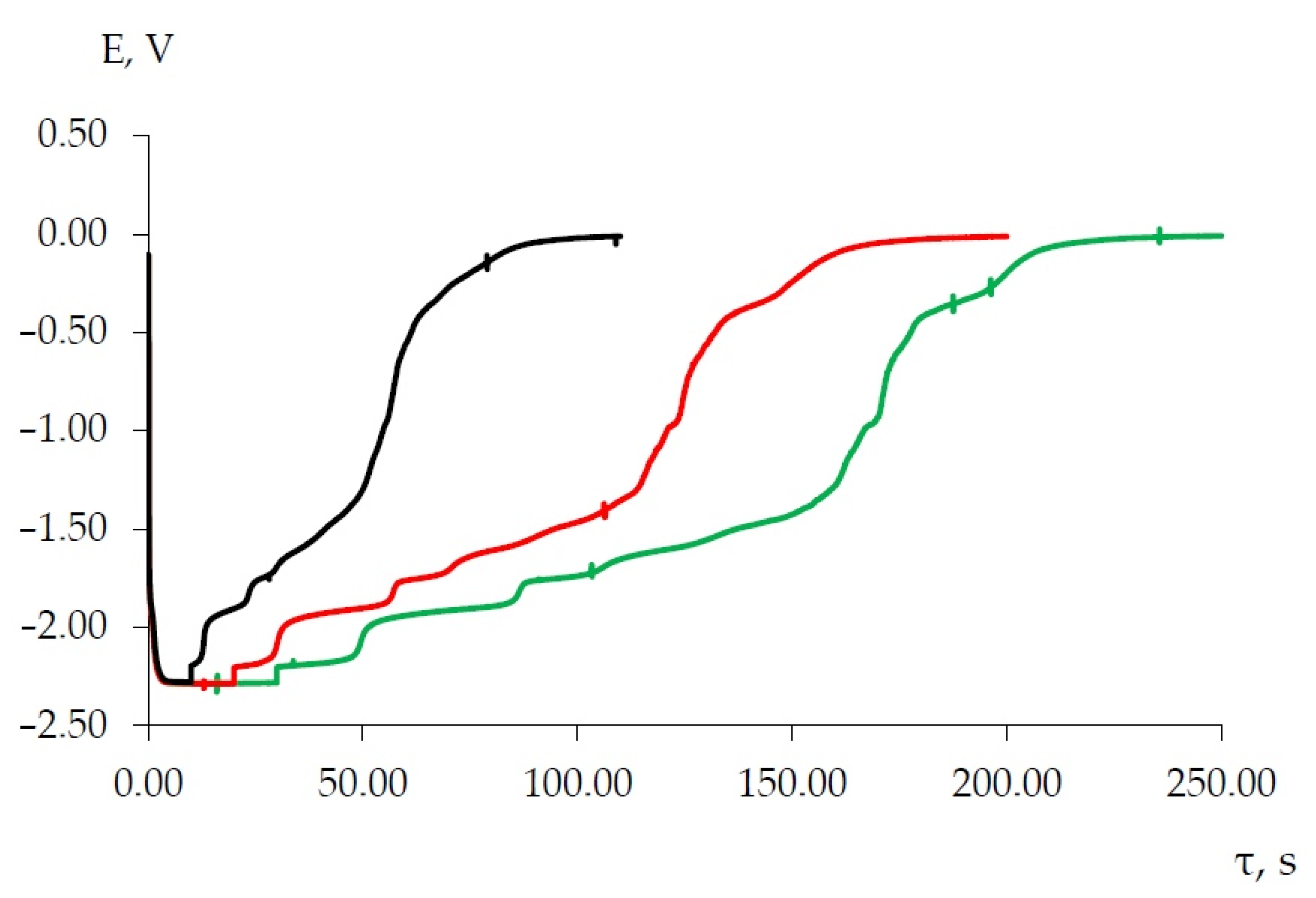
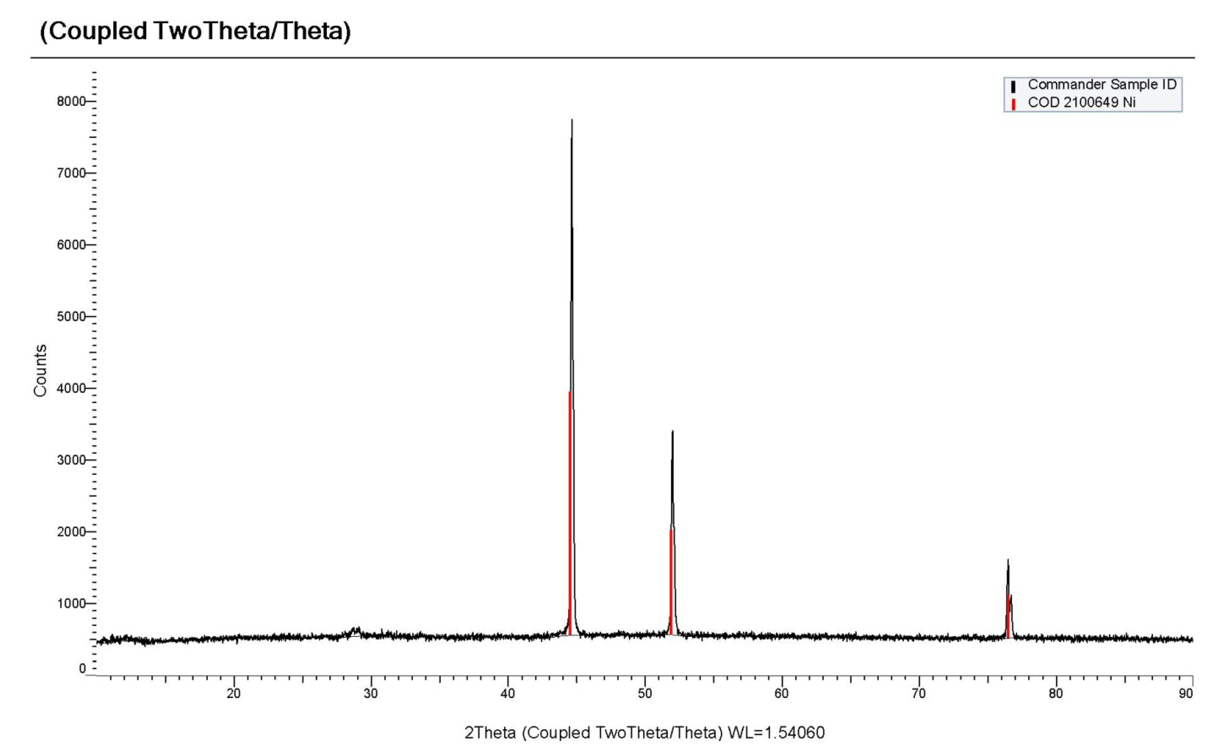
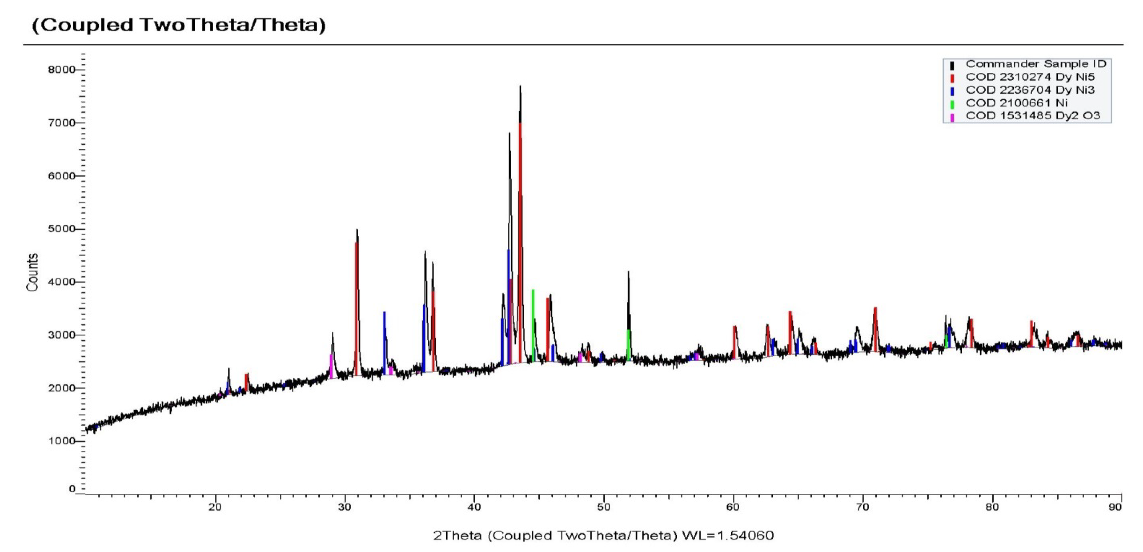
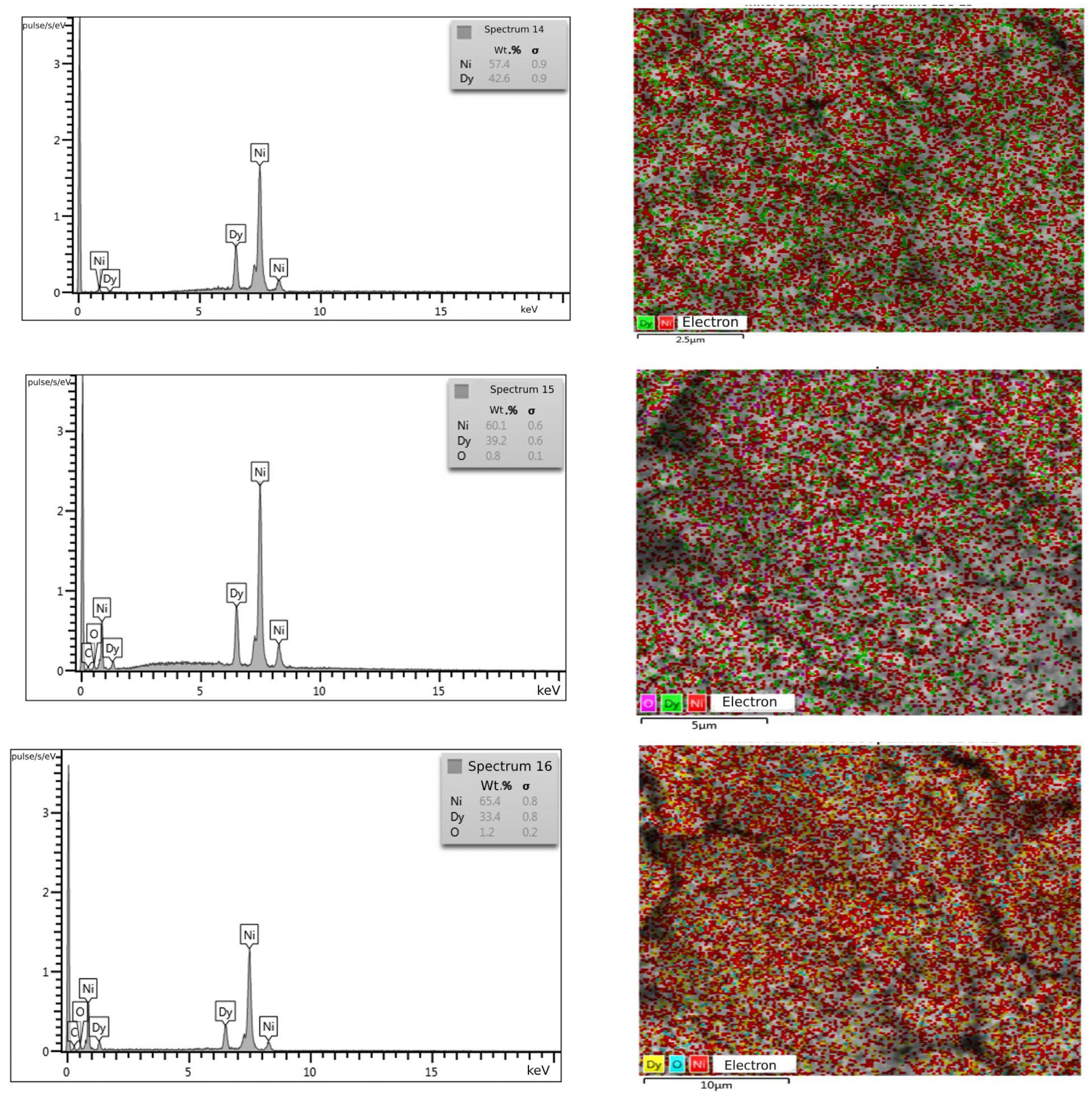
Potentiostatic Electrolysis and Deposit Characterization

According to the phase diagram of the Dy–Ni binary metal system [27,28], dysprosium and nickel form a series of intermetallic compounds Dy3Ni, Dy3Ni2, DyNi, DyNi2, DyNi3, Dy2Ni7, DyNi4, Dy4Ni17, DyNi5 and Dy2Ni17. Among all the phases, DyNi5 and DyNi are congruently melting compounds. The remaining phases are incongruently melting compounds formed by a peritectic reaction. Electrochemical formation of the intermetallic phases DyNi2, DyNi3, Dy2Ni7 and DyNi5 in the molten KCl-NaCl-DyCl3 (0.5 mol.%) system at 973 K and the LiCl-KCl-DyCl3 (0.5 mol.%) system at 673–773 K was confirmed by the authors [9,12,14] using scanning electron microscopy and X-ray diffraction measurements. From the EMF measurements of the intermetallic compounds in the Dy/Ni system, the authors of [29] calculated the standard Gibbs free energies of formation for DyNi2, DyNi3, Dy2Ni7 and DyNi5 in the temperature range of 673–773 K.
Based on the results of cyclic voltammetry, square-wave voltammetry and open circuit chronopotentiometry, potentiostatic electrolysis was carried out at the temperatures of 823–973 K on tungsten and nickel electrodes in the molten KCl-NaCl-CsCl-DyCl3-NiCl2 system via potentiostatic electrolysis at potentials up to −0.8 V relative to the silver chloride reference electrode for 2 h. According to the X-ray phase analysis, the electrolysis product is pure metallic nickel (Figure 14) with a face-centered cubic structure (Fm-3 m) (PDF in the XRD database: 04–0850). For the electrochemical synthesis of the DyxNiy intermetallic compounds, potentiostatic electrolysis was carried out at more negative potentials, −1.7 V, −1.9 V and −2.1 V, on tungsten and nickel electrodes at temperatures ranging from 823 to 973 K for 2 h in the KCl-NaCl-CsCl-DyCl3 (3.0 × 10⁻⁴ mol/cm3)-NiCl2 (0.3–0.5) × 10–10−4 mol/cm3) melt. As a result of the electrolysis on the tungsten electrode (d = 1.0 mm) and on a nickel plate, volumetric deposits were obtained in the form of a metal-salt “pear”.
According to the X-ray phase analysis, the electrolysis product at the potential of −1.7 V consisted mainly of the DyNi5 phase, a small amount of metallic nickel and the DyNi3 phase (Figure 15). The SEM and EDS analysis of the cathode deposit (Figure 16) shows that the Dy element is well dispersed in the intermetallic phase. The results of the quantitative EDS analysis (spectra 14, 15 and 16) sampled at different zones show that the deposits are composed of the Ni and Dy elements. The average content of Ni and Dy atoms (wt.%) in the sample is shown in the EDS spectra. The compositions obtained by EDS differ from the composition of DyNi5 found by XRD. To study the distribution of Dy and Ni elements in Dy–Ni alloys, an element mapping analysis was used.
The EDS-mapping analysis (Figure 16) of the elements shows that Dy is well dispersed in the Dy–Ni alloy.
With electrolysis at a more negative potential of −1.9 V, as can be seen from X-ray patterns (Figure 17), the cathode deposit consisted mainly of the DyNi3 and DyNi2 phases. Electrolysis at a potential of −2.1 V led to the formation of a phase richer in dysprosium content, the DyNi2 phase and the containment of a small amount of DyOCl and Dy2O3 (Figure 18). The formation of DyOCl and Dy2O3 is explained by the incorporation of DyCl3 into the intermetallic pores. When the cathode deposit is leached, DyCl3 is easily hydrolyzed to form oxychloride and oxide. A similar phenomenon in the preparation of Ce-Al alloys was previously discovered by Liu et al. [30] and Castrillejo et al. [31,32] in the preparation of Gd-Al and Sm-Al alloys. Intermetallic compounds DyNi3 and DyNi2 were obtained both with a cubic body-centered Fd-3 m structure and a hexagonal lattice (PDF in the XRD database: 65–5536).
Therefore, based on the results of the cyclic voltammetry, square-wave voltammetry and open circuit chronopotentiometry as well as potentiostatic electrolysis, the potentials of metallic nickel and dysprosium extraction on the inert tungsten and active nickel electrodes in the KCl-NaCl-CsCl-DyCl3-NiCl2 molten system differ by 1.5 V. This is why the electrochemical synthesis of the nickel and dysprosium intermetallic compounds is possible in the kinetic regime [6,7,8]. Under such conditions, the composition of the cathode deposit will depend on the electrolyte composition, current density and electrolysis potential. At the electrolysis current densities below the limiting diffusion current of nickel ion electroreduction or at potentials more positive than 1.2 V, the electroreduction of nickel takes place. At potentials more negative than −1.5 V and at current densities exceeding the limiting diffusion current of nickel ion electroreduction, DyxNiy intermetallic compounds will be formed on the nickel electrode or on the preliminary deposited on the tungsten electrode metallic nickel due to the Dy3+ ion electroreduction depolarization. The intermetallic compounds are formed according to the reaction diffusion of dysprosium atoms in the metallic nickel structure. In addition, the DyNi5 phase with a high concentration of nickel forms first, as the free Gibbs energy of formation of this phase has a smaller value among the intermetallic phases in the Dy–Ni system.
Dy3+ + 5 Ni + 3e = DyNi5
As the electrolysis potential or the electrolysis current density increases in the cathode area, the partial current of metallic dysprosium extraction increases and the phases of intermetallic compounds with a high concentration of metallic dysprosium appear.
7/3 DyNi5 + Dy3+ + 3e = 5/3 Dy2Ni7
3 Dy2Ni7 + Dy3+ + 3e = 7 DyNi3
2 DyNi3 + Dy3+ + 3e = 3 DyNi2
The summarized reaction is described by Equation (4).
The number of observed plateaus in the open circuit chronopotentiogram is less than the number of phases in the Dy–Ni state diagram. The formation reactions of some phases are kinetically retarded, and, therefore, the potential plateau corresponding to the formation of these alloys is not clearly observed. So, on the curves of the open circuit chronopotentiometry (Figure 8, Figure 9, Figure 12 and Figure 13), there is a potential plateau at −2.187 ± 0.010 V, corresponding to the Di3+/Dy equilibrium, and a number of other potential plateaus (1)–(4), corresponding to the equilibrium of two phases for (DyNi2/DyNi3), (DyNi3/Dy2Ni7), (Dy2Ni7/DyNi5) and (DyNi5/Ni), respectively (Figure 13). If the plateau potential (1)–(4) is expressed depending on the potential of Dy3+/Dy, then this potential directly corresponds to the EMF value of each two-phase coexisting state. To confirm the reproducibility of the experiment, the same measurements were repeated several times in each two-phase region. Table 2 presents the transformation reactions and the EMF values obtained for two-phase coexisting states from several independent measurements of the EMF at 823 K in a KCl-NaCl-CsCl-DyCl3-NiCl2 melt.
Based on the results of cyclic and square-wave voltammetry whereby dysprosium exists in the chloride melt in the form of ions with an oxidation state of +3 and according to the values of EMF (E (V, vs. Dy3+/Dy), the relative partial molar Gibbs energies and Dy activities in the intermetallic compounds DyxNiy (Table 3), using the following equations, are calculated:
Δ G ¯ Dy   Dy x Ni y = 3 FE
a Dy Dy x Ni y = exp Δ G ¯ Dy   Dy x Ni y RT  
where Δ G ¯ Dy is a relative partial free molar Gibbs energy for the Dy component and a Dy   is the Dy component activity.
The relative partial molar Gibbs free energies and Dy activities in DyxNiy intermetallic compounds obtained in this work were compared with the literature data [31]. The existing discrepancies in the values of the relative partial molar free energy of Gibbs and the activity of dysprosium are associated with a temperature higher by 50–150 K in the eutectic molten system KCl-NaCl-CsCl compared to the eutectic KCl-LiCl.

4. Conclusions

The methods of cyclic and square-wave voltammetry, chronopotentiometry, chronovoltammetry and open-circuit chronopotentiometry were used to study the electrochemical behavior of dysprosium ions and their co-electroreduction with nickel ions on an inert tungsten and active nickel electrodes in a eutectic KCl-NaCl-CsCl melt at a temperature of 823 K. The electroreduction of Dy3+ ions in the eutectic KCl-NaCl-CsCl melt at a temperature of 823 K proceeds reversibly in a single three-electron stage up to polarization rates of 0.1 V/s. At higher polarization rates, the charge transfer stage is slower.
The open circuit chronopotentiograms allowed for the determination of the electrode potential E(Dy3+/Dy) = −(2.098–2.130) V in the KCl-NaCl-CsCl eutectic melt at a temperature of 823 K. The waves of the Dy3+ and Ni2+ ion co-electroreduction with the formation of corresponding intermetallic phases were recorded by the cyclic and square-wave voltammograms and open circuit chronopotentiograms in the eutectic KCl-NaCl-CsCl melt containing Dy3+ and Ni2+ ions at a temperature of 823 K on an inert tungsten and active nickel electrodes. The DyxNiy intermetallic compounds were synthesized by the potentiostatic electrolysis of the KCl-NaCl-CsCl melt, containing various concentrations of DyCl3 and NiCl2 at the potentials of −1.7 V, −1.9 V and −2.1 V on the tungsten and nickel electrodes at 823–973 K. XRD and SEM-EDS analyses of the cathode deposits show the formation of DyNi5, DyNi3 and DyNi2 phases, respectively. It has been established that the more negative electrolysis potential results in the formation of the cathode deposit containing more intermetallic phases with a high content of dysprosium. EMF was measured for the DyxNiy intermetallic compounds in two-phase coexisting states at the temperature of 823 K. The relative partial free molar Gibbs energy and dysprosium activity in the DyxNiy intermetallic compounds were calculated from the EMF values.

Author Contributions

Conceptualization, K.B.K.; methodology, K.B.K.; validation, K.B.K.; formal analysis, Z.Z.A., Z.A.Z. and A.S.K.; investigation, Z.Z.A., V.A.K. (Vadim A. Kvashin), Z.A.Z. and A.S.K.; resources, K.B.K., V.A.K. (Vadim A. Kvashin), Z.A.Z. and D.P.M.; data curation, Z.Z.A., V.A.K. (Vadim A. Kvashin) and A.A.M.; writing—original draft preparation, K.B.K., Z.A.Z., V.A.K. (Vadim A. Kvashin) and A.S.K.; writing—review and editing, K.B.K., D.P.M. and A.S.K.; visualization, A.S.K. and V.A.K. (Vadim A. Kovrov); supervision, K.B.K.; project administration, A.A.K. and A.A.M.; funding acquisition, K.B.K. and A.A.K. All authors have read and agreed to the published version of the manuscript.

Funding

This research was funded by the Russian Science Foundation (grant number No. 23-23-00360).

Data Availability Statement

Not applicable.

Conflicts of Interest

The authors declare no conflict of interest.

References

  1. Itin, V.I.; Naiborodenko, Y.S. Vysokotemperaturnyi Elecktrokhimicheskiy Sintez Intermetallicheskik Soedineniy (High Temperature Synthesis of Intermetallic Compounds); Tomsk University: Tomsk, Russia, 1989; p. 214. [Google Scholar]
  2. Martin, D.L.; Elnora, N.Y. Nickel-Lanthanum Alloy Produced by a Reduction-Diffusion Process. U.S. Patent 3918933, 24 July 1974. [Google Scholar]
  3. Martin, D.L.; Elnora, N.Y. Nickel-Lanthanum Alloy Produced by a Reduction-Diffusion Process. U.S. Patent 3883346, 25 April 1974. [Google Scholar]
  4. Kamarzin, A.A.; Osadchaja, L.I.; Podojnitsyn, S.V.; Stonoga, Y.A.; Zelenin, Y.M.; Bondin, V.V. Method of Preparing Composition for Hydrogen Accumulation. RU Patent 2113400, 10 April 1997. [Google Scholar]
  5. Kasimtsev, A.V. Method for Making Reversible Hydrogen-Sorbing Alloy Combination. RU Patent 2351534, 29 June 2007. [Google Scholar]
  6. Shapoval, V.I.; Malyshev, V.V.; Novoselova, I.A.; Kushkhov, K.B. Modern problems in the high-temperature electrochemical synthesis of the compounds of Group IV–VI transition metals. Russ. Chem. Rev. 1995, 64, 125–132. [Google Scholar] [CrossRef]
  7. Kushkhov, K.B.; Tlenkopachev, M.R. Electrochemical Synthesis of Intermetallic and Refractory Compounds Based on Rare-Earth Metals in Ionic Melts: Achievements and Prospects. Russ. J. Gen. Chem. 2011, 91, 251–272. [Google Scholar] [CrossRef]
  8. Kushkhov, K.B.; Tlenkopachev, M.R. Electrochemical synthesis of intermetallic and refractory compounds based on rare-earth metals in ionic melts: Achievements and prospects. Curr. Top. Electrochem. 2020, 22, 57–77. [Google Scholar] [CrossRef]
  9. Konishi, H.; Nohira, T.; Ito, Y. Formation and phase control of Dy alloy films by electrochemical implantation and displantation. J. Electrochem. Soc. 2001, 148, C506. [Google Scholar] [CrossRef]
  10. Konishi, H.; Nohira, T. Morphology control of Dy–Ni alloy films by electrochemical displantation. Electrochem. Solid-State Lett. 2002, 5, 37–39. [Google Scholar] [CrossRef]
  11. Konishi, H.; Nohira, T.; Ito, Y. Kinetics of DyNi2 film growth by electrochemical implantation. Electrochim. Acta 2003, 48, 563–568. [Google Scholar] [CrossRef]
  12. Yasuda, K.; Koboyashi, S.; Nohira, T.; Hagiwara, R. Electrochemical formation of Dy–Ni alloys in molten KCl–NaCl–DyCl3. Electrochem. Acta 2013, 106, 293–300. [Google Scholar] [CrossRef]
  13. Su, L.L.; Liu, K.; Liu, Y.L.; Wang, L.; Yuan, L.Y.; Wang, L.; Li, Z.I.; Zhao, X.L.; Chai, Z.F.; Shi, W.Q. Electrochemical behaviors of Dy(III) and its co–reduction with Al (III) in molten LiCl–KCl salts. Electrochem. Acta 2014, 147, 87. [Google Scholar] [CrossRef]
  14. Kushkhov, K.; Ali, Z.; Khotov, A.; Kholkina, A. Mechanism of Dy3+ and Nd3+ Ions Electrochemical Coreduction with Ni2+, Co2+, and Fe3+ Ions in Chloride Melts. Materials 2021, 14, 7440. [Google Scholar] [CrossRef]
  15. Kushkhov, K.B.; Qahtan, A.M.F.; Uzdenova, A.S.; TIenkopachev, M.R.; Uzdenova, L.A. Electroreduction of dysprosium ions on different electrodes in KCl-NaCl-CsCl melt at T = 823 K. Rasplavy 2014, 4, 60–69. (In Russian) [Google Scholar]
  16. Kushkhov, H.B.; Uzdenova, A.S.; Saleh, M.M.A.; Qahtan, A.M.F.; Uzdenova, L.A. The Electroreduction of Gadolinium and Dysprosium Ions in Equimolar NaCl-KCl Melt. Am. J. Anal. Chem. 2013, 4, 39–46. [Google Scholar] [CrossRef]
  17. Bard, A.J.; Faulkner, L.R. Electrochemical Methods, 2nd ed.; Wiley: New York, NY, USA, 2000. [Google Scholar]
  18. Stolz, F. Electroanalytical Methods. Theory and Practice; Springer: Berlin/Heidelberg, Germany, 2010; 326p. [Google Scholar]
  19. Jaeger, E.; Zalkind, F. Methods of Electrochemistry Measurements; Mir Publishers: Mir, Belarus, 1977; 585p. [Google Scholar]
  20. Castrillejo, Y.; Bermejo, M.R.; Barrado, E.; Pardo, R.; Barrado, E.; Martinez, M. Electrochemical Behavior of Dy in LiCl-KCl Eutectic Melt on W and Al Electrodes. J. Electrochem. Soc. 2005, 50, 2047–2057. [Google Scholar]
  21. Ramaley, L.; Krause, M.S. Theory of square wave voltammetry. Analyt. Chem. 1969, 41, 1362–1365. [Google Scholar] [CrossRef]
  22. Settle, J.L.; Nagy, Z. Metal deposition-dissolution in molten halides-on the question of measurability of fast electrode-reaction rates. J. Electrochem. Soc. 1985, 132, 1619–1627. [Google Scholar] [CrossRef]
  23. Nohira, T.; Kobayashi, S.; Kobayashi, K.; Hagivara, R.; Oishi, T.; Konishi, H. Electrochemical formation of Nd–Ni alloys in molten LiF–CaF2–NdF3. J. Electrochem. Soc. 2011, 158, E142. [Google Scholar]
  24. Kobayashi, K.; Nohira, T.; Kobayashi, S.; Yasuda, K.; Hagivara, R.; Oishi, T.; Konishi, H. Electrochemical formation of Dy–Ni alloys in molten LiF–CaF2–DyF3. J. Electrochem. Soc. 2012, 159, E193. [Google Scholar] [CrossRef]
  25. Nourry, C.; Massot, L.; Camelot, P.; Taxil, P. Formation of Nd–Ni alloys by Nd (III) electrochemical reduction in molten fluoride. J. New Mater. Electrochem. Syst. 2007, 10, 117–122. [Google Scholar]
  26. Iida, T.; Nohira, T.; Ito, Y. Electrochemical of Sm–Ni alloy films in a molten LiCl–KCl–SmCl3 system. Electrochem. Acta 2001, 46, 2537–2544. [Google Scholar] [CrossRef]
  27. Lyakisheva, N.M. Phase Diagrams of Double Metallic Systems: Reference Book (Diagramma Sostoyaniy Dvoinykh Metallicheskihk System: Spravochnik); Mashinostroyeniye: Moskva, Russia, 1999; Volume 3. (In Russian) [Google Scholar]
  28. Massalski, T.B.; Okamoto, H.; Subramanian, P.R.; Kacprzak, L. Binary Alloy Phaze Diagrams, 2nd ed; ASM International: Materials Park: Novelty, OH, USA, 1996. [Google Scholar]
  29. Konishi, H.; Nishikori, T.; Nohira, T.; Ito, J. Thermodynamic properties of Dy/Ni intermetallic compounds. Electrochem. Acta 2003, 48, 1403–1408. [Google Scholar] [CrossRef]
  30. Liu, Y.L.; Yan, Y.D.; Zhang, M.L.; Zheng, J.N.; Zhao, Y.; Wang, P.; Yin, T.Q.; Xue, Y.; Jing, Z.-Y.; Han, W. Electrochemical Syntesis of Sm-Ni Alloy Magnetic Materials by Co-reduction of Sm(III) and Ni(II) in LiCl-KCl-SmCl3-NiCl2 Melt. J. Electr. Soc. 2016, 163, D672–D681. [Google Scholar] [CrossRef]
  31. Castrillejo, Y.; Ernandez, P.; Fernandez, R.; Barrado, E. Electrochemical behavior of terbium in the eutectic LiCl–KCl in Cd liquid electrodes–Evaluation of thermochemical properties of the TbCdx intermetallic compounds. Electrochem. Acta 2014, 147, 743. [Google Scholar] [CrossRef]
  32. Yin, T.Q.; Xue, Y.; Yan, Y.D.; Zheng, Y.; Song, Y.L.; Wang, G.L.; Zhang, M.L.; Qiu, M.; Hu, D.H. Electrochemical synthesis and thermodynamic properties of Pr–Ni intermetllic compounds in a LiCl–KCl–NiCl2–PrCl3 Melt. ChemElectroChem 2019, 6, 876. [Google Scholar] [CrossRef]
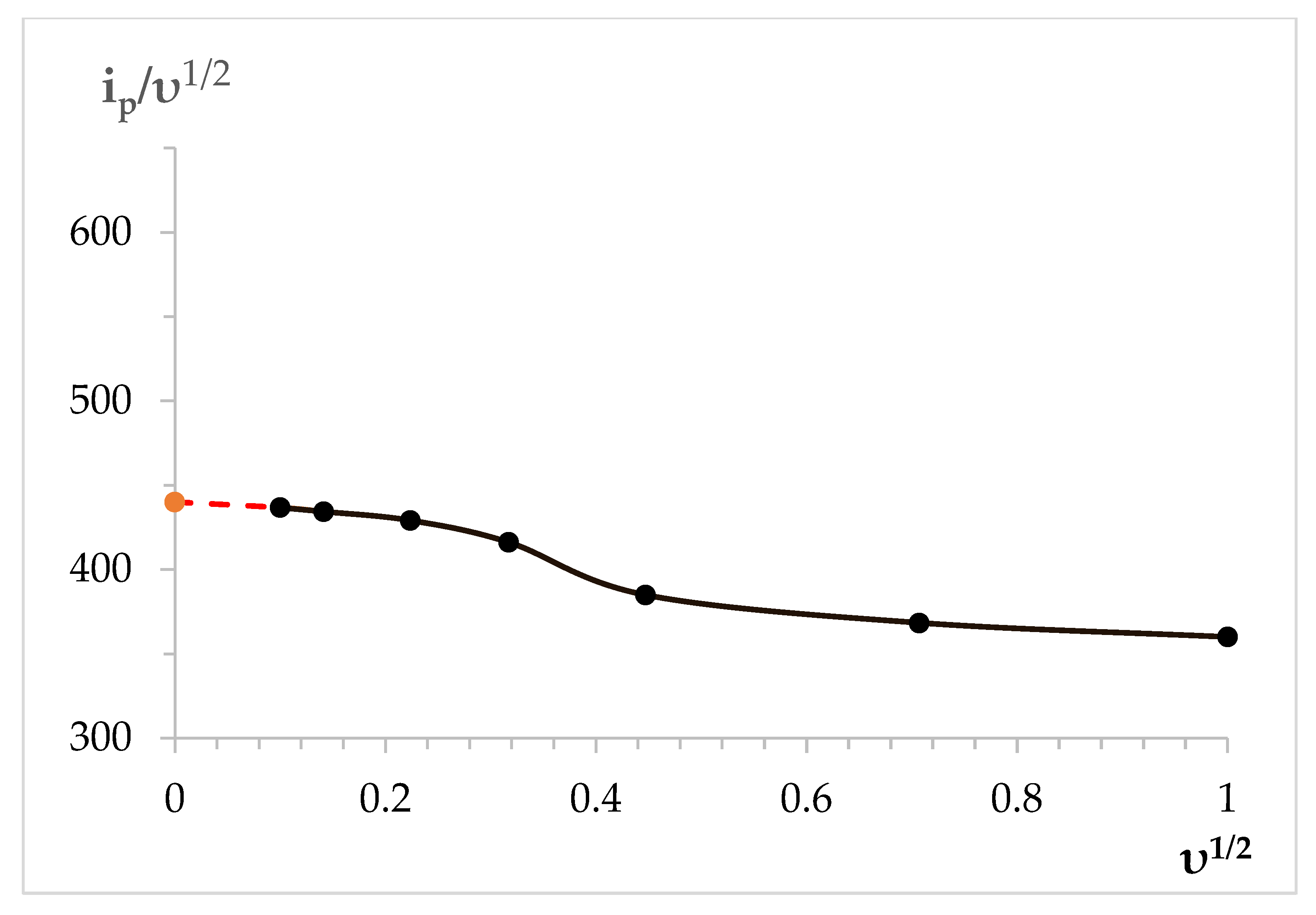
Figure 1. Cyclic chronovoltammogram recorded on the tungsten electrode in the molten KCl-NaCl-CsCl eutectic containing 3.0 × 10⁻⁴ mol/cm3 of DyCl3 at different polarization rates. V/s: 1—0.2 (background electrolyte); 3—0.02; 4—0.05; 5—0.1; 6—0.2, T = 823 K, Scathode = 0.6 cm2.
Processes 11 02818 g001
Figure 2. Dependence of the ip1/2 vs. υ1/2 of dysprosium ion electroreduction on the tungsten electrode in the molten KCl-NaCl-CsCl eutectic containing 3.0 × 10⁻⁴ mol/cm3 DyCl3 at T = 823 K.
Processes 11 02818 g002
Figure 3. Square-wave voltammogram of dysprosium ion electroreduction on the tungsten electrode in the molten KCl-NaCl-CsCl eutectic containing 3.0 × 10⁻⁴ mol/cm3 DyCl3. T = 823 K, ω = 25 Hz, Selectrode = 0.6 cm2.
Processes 11 02818 g003
Figure 4. Open circuit chronopotentiometry recorded at the tungsten electrode in the KCl-NaCl-CsCl melt containing DyCl3 (3.0 × 10⁻⁴ mol/cm3). Polarization current was 0.05 A. Polarization time, s: 1—5.0; 2—7.5. Selectrode = 0.6 cm2, T = 823 K.
Processes 11 02818 g004
Figure 5. Cyclic voltammograms of Dy3+ and Ni2+ ion co-electroreduction on the tungsten electrode in the KCl-NaCl-CsCl melt at 823 K and different reverse potentials: 1—(−2.5 V); 2—(−2.6 V); 3—(−2.45 V); 4—(−2.3 V). Polarization rate (υ) = 0.2 V/s, Scathode = 0.54 cm2, C (DyCl3) = 5.0 × 10⁻⁴ mol/cm3, C (NiCl2) = 0.5 × 10⁻⁴ mol/cm3.
Processes 11 02818 g005
Figure 6. Chronopotentiograms of the KCl-NaCl-CsCl-DyCl3-NiCl2 system recorded on the tungsten electrode at 823 K and different polarization currents: black line—0.05 A; red line—0.1 A; green line—0.15 A; blue line—0.2 A; violet line—0.3 A. Galvanic pulse time—10 s, Scathode = 0.6 cm2, C (DyCl3) = 3.0 × 10⁻⁴ mol/cm3, C (NiCl2) = 0.5 × 10⁻⁴ mol/cm3.
Processes 11 02818 g006
Figure 7. Square-wave voltammetry of the KCl-NaCl-CsCl-DyCl3-NiCl2 system recorded at the tungsten electrode at 823 K and ω = 25 Hz, Scathode = 0.54 cm2, C (DyCl3) = 5.0 × 10⁻⁴ mol/cm3 and C (NiCl2) = 0.5 × 10⁻⁴ mol/cm3.
Processes 11 02818 g007
Figure 8. Open circuit chronopotentiometry recorded at the tungsten electrode in molten KCl-NaCl-CsCl-DyCl3-NiCl2 at 823 K. Polarization current, A: 1—0.05; 2—0.1; 3—0.15; 4—0.2 A. Galvanic pulse time—10 s, Scathode = 0.54 cm2, C (DyCl3) = 5.0 × 10⁻⁴ mol/cm3, C (NiCl2) = 0.5 × 10⁻⁴ mol/cm3.
Processes 11 02818 g008
Figure 9. Open circuit chronopotentiometry recorded at the tungsten electrode in molten KCl-NaCl-CsCl-DyCl3-NiCl2 at 823 K. Polarization current, A: 1—0.05; 2—0.1; 3—0.15; 4—0.2 A. Galvanic pulse time—20 s, Scathode = 0.54 cm2, C (DyCl3) = 5.0 × 10⁻⁴ mol/cm3, C (NiCl2) = 0.5 × 10⁻⁴ mol/cm3.
Processes 11 02818 g009
Figure 10. Cyclic voltammograms of Dy3+ and Ni2+ ion co-electroreduction on the nickel electrode in the molten KCl-NaCl-CsCl-DyCl3-NiCl2 system at 823 K and different reverse potentials: 1—(−2.1 V); 2—(–2.0–). Polarization rate (υ) = 0.2 V/s, Scathode = 0.57 cm2, C (DyCl3) = 3.0 × 10⁻⁴ mol/cm3, C (NiCl2) = 0.5 × 10⁻⁴ mol/cm3.
Processes 11 02818 g010
Figure 11. Square-wave voltammogram of the molten KCl-NaCl-CsCl-DyCl3-NiCl2 system on the nickel electrode at 823 K. Frequency (ω) = 20 Hz, Scathode = 0.57 cm2, C (DyCl3) = 3.0 × 10⁻⁴ mol/cm3, C (NiCl2) = 0.5 × 10⁻⁴ mol/cm3.
Processes 11 02818 g011
Figure 12. Open circuit chronopotentiogram of the molten KCl-NaCl-CsCl- DyCl3-NiCl2 system recorded on the nickel electrode at 823 K. Polarization current, A: 1—0.05 A; 2—0.1; 3—0.15; 4—0.2. Galvanic pulse time was 10 s. Scathode = 0.57 cm2, C (DyCl3) = 3.0 × 10⁻⁴ mol/cm3, C (NiCl2) = 0.5 × 10⁻⁴ mol/cm3.
Processes 11 02818 g012
Figure 13. Open circuit chronopotentiogram of the molten KCl-NaCl-CsCl-DyCl3-NiCl2 system recorded on the nickel electrode at 823 K. Polarization current—0.2 A. Galvanic pulse time, s: black curve—10; red curve—20; green curve—30. Scathode = 0.57 cm2, C (DyCl3) = 3.0 × 10⁻⁴ mol/cm3, C (NiCl2) = 0.5 × 10⁻⁴ mol/cm3.
Processes 11 02818 g013
Figure 14. X-ray phase analysis of the potentiostatic electrolysis product obtained in KCl-NaCl-CsCl-DyCl3 (3.0 × 10⁻⁴ mol/cm3) − NiCl2 (0.5 × 10⁻⁴ mol/cm3). T = 973 K. Electrolysis potential −0.8 V. Electrolysis time was 2 h.
Processes 11 02818 g014
Figure 15. X-ray phase analysis of the potentiostatic electrolysis product obtained in KCl-NaCl-CsCl-DyCl3 (3.0 × 10⁻⁴ mol/cm3) − NiCl2 (0.5 × 10⁻⁴ mol/cm3). T = 973 K. Electrolysis potential −1.7 V. Electrolysis time was 2 h.
Processes 11 02818 g015
Figure 16. SEM-EDX analysis of the Dy–Ni intermetallic compound obtained by the potentiostatic electrolysis of the KCl-NaCl-CsCl-DyCl3 (3.0 × 10⁻⁴ mol/cm3) − NiCl2 (0.5 × 10⁻⁴ mol/cm3) system at 973 K. Electrolysis potential was −1.7 V. Electrolysis time was 2 h.
Processes 11 02818 g016aProcesses 11 02818 g016b
Figure 17. X-ray diffraction pattern on the potentiostatic electrolysis product obtained in the KCl-NaCl-CsCl-DyCl3 (3.0 × 10⁻⁴ mol/cm3) − NiCl2 (0.5 × 10⁻⁴ mol/cm3) system at 973 K. Electrolysis potential was −1.9 V. Electrolysis time was 2 h.
Processes 11 02818 g017
Figure 18. X-ray diffraction pattern on the potentiostatic electrolysis product obtained in the KCl-NaCl-CsCl-DyCl3 (3.0 × 10⁻⁴ mol/cm3) − NiCl2(0.5 × 10⁻⁴ mol/cm3) system at 973 K. Electrolysis potential was −2.1 V. Electrolysis time was 2 h.
Processes 11 02818 g018
Table 1. Values of some parameters of Dy3+ ion electroreduction in the KCl-NaCl-CsCl eutectic melt at a temperature of 823 K. C(DyCl3) = 2.0 × 10⁻⁴ mol/cm3.
υ,
V/s
Ip,
mA/cm2
ip1/2
mA·s1/2/cm2V1/2
Eкp
V
Eкp/2
V
Δ E
V
nnα)
0.0143.8438.7−2.221−2.1670.0542.9
0.0261.4434.3−2.262−2.2100.0523.0
0.0595.95429.11−2.274−2.2210.0532.9
0.1131.6416.1−2.295−2.2420.0532.9
0.2172.1384.4−2.304−2.2410.0632.5
0.5260.5368.4−2.292−2.2200.0722.2
1.0354.1354.1−2.378−2.2940.0841.8
Table 2. Transformation relations and obtained EMF values for the two-phase co-existing states of the DyxNiy intermetallic compounds in the KCl-NaCl-CsCl-DyCl3 (3.0 × 10⁻⁴ mol/cm3) − NiCl2 (3.0 × 10⁻⁵ mol/cm3) melt at 823 K.
Plateau No. (Figure 13)E (V, vs. Dy3+/Dy)Reactions
(1)0.243 ± 0.012 DyNi3 + Dy3+ + 3 e ⇄ 3 DyNi2
(2)0.417 ± 0.013 Dy2Ni7 + Dy3+ + 3e ⇄ 7 DyNi3
(3)0.523 ± 0.0127/3 DyNi5 + Dy3+ + 3e ⇄ 5/3 (Dy2Ni7)
(4)0.712 ± 0.0195 Ni + Dy3+ + 3e ⇄ DyNi5
Table 3. Thermodynamic properties of dysprosium for intermetallic DyxNiy compounds in two-phase co-existing states at 823 K.
Phase EquillibriaE (V, vs. Dy3+/Dy) Δ G ¯ D y ( kJ / mol   Dy ) aDy
Two-phase co-existing state between DyNi2/DyNi30.243 ± 0.01−70.35 ± 2.9(3.43 ± 0.14) × 10−5
Two-phase co-existing state between DyNi3/Dy2Ni70.417 ± 0.01−120.72 ± 2.9(2.18 ± 0.05) × 10−8
Two-phase co-existing state between Dy2Ni7/DyNi50.523 ± 0.012−151.4 ± 3.4(2.47 ± 0.06) × 10−10
Two-phase co-existing state between DyNi5/Ni0.712 ± 0.019−206.12 ± 5.5(8.3 ± 0.22) × 10−14
Disclaimer/Publisher’s Note: The statements, opinions and data contained in all publications are solely those of the individual author(s) and contributor(s) and not of MDPI and/or the editor(s). MDPI and/or the editor(s) disclaim responsibility for any injury to people or property resulting from any ideas, methods, instructions or products referred to in the content.

