Article

Novel Process for Butyl Acetate Production via Membrane Reactor: A Comparative Study with the Conventional and Reactive Distillation Processes

by
Abdulrahman A. Al-Rabiah
*,
Abdullah E. Alqahtani
,
Rayan K. Al Darwish
and
Abdulaziz S. Bin Naqyah
Chemical Engineering Department, College of Engineering, King Saud University, Riyadh 11421, Saudi Arabia
*
Author to whom correspondence should be addressed.
Processes 2022, 10(9), 1801; https://doi.org/10.3390/pr10091801
Submission received: 17 August 2022 / Revised: 1 September 2022 / Accepted: 5 September 2022 / Published: 7 September 2022

Abstract

:
Butyl acetate (BuAc) is widely used as a solvent in many applications, mainly in the food and pharmaceutical industries. The conventional process for BuAc production is both capital and energy intensive. The purification process involves the separation of BuAc from the azeotropic mixture of water and n-butanol, which is difficult to accomplish using a simple distillation unit. In this study, a membrane reactor (MR) for BuAc production via the esterification of n-butanol was investigated. The MR using the Amberlyst-15 catalyst was modeled and validated with previously reported experimental data, and a good agreement was achieved. The ultimate conversion of n-butanol using the MR was 92.0%, compared to 69.8% for the conventional reactor. This study is the first to propose an intensified MR-based process for butyl acetate production. The MR-based process was developed and rigorously simulated using Aspen Plus for an annual plant capacity of 92,500 metric tons of BuAc. The MR-based process is environmentally friendly regarding CO2 emissions, with a reduction of 80% compared to the conventional process. The economic analysis of the MR-based process shows a payback period of 2.7 years and a return on investment (ROI) of 23.1%. The MR-based process for BuAc production is a promising technology that provides similar key benefits as compared to the reactive distillation (RD) process.

Graphical Abstract

1. Introduction

Butyl acetate (BuAc) is commonly used as a solvent across many industries, mostly in the manufacturing of adhesives, lacquers, coatings, and paints [1,2,3,4,5,6]. The pharmaceutical and cosmetic industries use butyl acetate as an extraction agent or solvent. In the food industry, BuAc is used to synthesize fruit flavors [7]. BuAc is produced on an industrial scale by n-butanol esterification with acetic acid. Strong acids are required to catalyze this reversible reaction using solid-acidic catalysts such as ion exchange resins [8,9,10,11].
The membrane reactor (MR) is a catalytic reactor that combines reaction and separation processes to increase the reaction yield when the thermodynamic equilibrium limits the conversion [12,13]. The separation inside the MR is performed through a selective membrane that allows some components to permeate through to the other side. In this way, the thermodynamic is shifted to an upper limit so the reaction can proceed forward to reach a higher conversion. Guangrui Liu et al. experimentally studied the synthesis of BuAc using the esterification of n-butanol through a catalytic membrane reactor (CMR) at 363 K [14]. Liu et al. studied the performance of pervaporation-assisted esterification using a cross-linked polyvinyl alcohol (PVA) membrane [15]. Khajavi et al. studied the esterification reaction in a hydroxy sodalite membrane reactor catalyzed by Amberlyst-15 [16]. Many studies have been published on testing different membrane reactors and water flux through different membranes under various reactive conditions. For instance, Zeolite A, Zeolite T, MOR, and NaA are water-selective membranes that were experimentally tested for the esterification of ethanol with lactic acid [17,18,19]. Although they were tested for different reactions, they showed good results for water flux and selectivity, which could be used for n-butanol esterification.
The conventional process for butyl acetate synthesis was studied by Shen et al., and a continuous stirred-tank reactor (CSTR) and three distillation columns were utilized for the process configuration [20]. The downside of the conventional process is that the esterification reaction is limited by the thermodynamic equilibrium. The conversion is typically low and does not exceed 70% [21]. In addition, the downstream purification process of BuAc using distillation columns is relatively complex and capital-intensive due to the azeotropic behavior of n-butanol and water [8].
Reactive distillation (RD) significantly reduces the energy and capital costs of the process by combining the reaction and separation equipment into one operating unit [22]. Several studies in the literature investigated the utilization of reactive distillation for the production of butyl acetate [2,8,23,24]. The RD technology can be utilized in a conventional multi-unit process to reduce energy and capital costs by five times [25]. However, one major drawback of RD technology is the complexity of the design and operation.
No previous work has been reported in the literature on developing an MR-based process for butyl acetate production via n-butanol esterification. Based on previous experimental studies, the goal of this research is to create a mathematical model to demonstrate the MR performance and validate the model results with the experimental data. The MR model is then utilized to develop a novel MR-based process for butyl acetate production. The new MR-based process is compared with the two well-known technologies: the conventional and the RD-based processes. The three processes are also evaluated based on technical performance, environmental impact, and economic profitability.

2. Reaction Chemical Equilibrium

The esterification reaction of n-butanol (BuOH) with acetic acid (AA) is shown in Equation (1):
BuOH +   AA   BuAC + H 2 O                       Δ H 298 = 29.312   kJ / mol
Due to the non-ideality of the system in the esterification reaction, the non-random two-liquid (NRTL) equation of state has been selected to determine the vapor-liquid-liquid equilibrium (VLLE) [23]. The NRTL model included in Aspen Plus was used to simulate the esterification reaction. The change of equilibrium conversion of n-butanol with the reaction temperature was determined using the equilibrium reactor as shown in Figure 1. It was noticed that the conversion decreases as the temperature increases, which confirms that the n-butanol esterification reaction is exothermic, as shown by Equation (1).
It should be emphasized that the n-butanol and water form an azeotropic mixture, which makes the separation more complicated. Shen et al. used 1,4-butanediol as a solvent to separate n-butanol from water [20]. A residue curve between n-butanol, water, and the solvent (1,4-butanediol) has been created using Aspen Plus, as shown in Figure 2. An azeotrope point is formed at 23.5% butanol and 76.5% water at a temperature of 91.6 °C (364.7 K).

3. Model Development

A mathematical model for the MR was developed based on the experimental data reported [16]. In the experimental work, a hydroxyl sodalite membrane was used in the reactor for the water separation from organic compounds.
The water permeation flux for the membrane reactor model was obtained from Khajavi et al. [16]. The Amberlyst-15 catalyst was used in the membrane reactor. The reaction rate expression using the Amberlyst-15 catalyst reported by Khajavi et al. is described in Equations (2)–(4) [16]:
r a t e   o f   r e a c t i o n   ( r ) = k F ( C A A C B u O H C B u A c C H 2 O k e q )
                                          k F = 0.103 L mol   min
k e q = 3.51
where r is the reaction rate, C i is the concentration of the individual species, k F is the reaction rate constant, and k e q is the equilibrium constant.
The concentration of species i is expressed by:
C i = N i / V
where
V =   N i M i ρ i
N i is the number of moles, V is the reaction volume, M i is the molar mass, and ρ i is the density.
The change in the number of moles over time of species i is expressed as:
d N i d t = r i V J i A
where r i is the formation rate of component i, J i is the membrane flux of component i, A is the effective area of the membrane.
Since there are only traces of n-butanol, butyl acetate, and acetic acid that can permeate through the membrane, these traces are assumed to be negligible. Therefore, the total flux can be assumed to equal the water flux (   J W ), which is calculated by Equation (8).
J W = P W C W
where P W is the permeability coefficient of water.
Equations (9)–(12) were used to solve for the flowrates of the components along the length of the membrane reactor:
1 A c d ( F B u O H ) d ( z ) = k F ( C A A C B u O H C B u A c C H 2 O k e q ) J B u O H A
1 A c d ( F A A ) d ( z ) = k F ( C A A C B u O H C B u A c C H 2 O k e q ) J A A A
1 A c d ( F B u A c ) d ( z ) = k F ( C A A C B u O H C B u A c C H 2 O k e q ) J B u A c A
1 A c d ( F W ) d ( z ) = k F ( C A A C B u O H C B u A c C H 2 O k e q ) J W A
where F i is the flowrate of component i , A c is the cross-sectional area, and   z is the length of the membrane reactor. The model was solved using ODE45, which is based on an explicit Runge–Kutta (4,5) formula embedded in MATLAB software, R2020a (9.8) (Portola Valley, CA, USA).

4. Membrane Reactor Performance

The developed model was validated to accurately simulate the membrane reactor performance. A feed ratio of 1:1 for n-butanol and acetic acid was used in the experimental work. Table 1 lists the parameters used for the mathematical model [16].
Figure 3 illustrates the concentration as a function of time obtained by the model and compares it with the experimental work conducted by Khavaji et al. [16]. The obtained results were in good agreement with the experimental work. Figure 4 illustrates the statistical variation of concentration results of theoretical calculations vs. experimental with the resultant coefficient of determination (R2) of 0.9973. The coefficient of determination indicates a good agreement between the experimental and theoretical results. Table 2 shows the model conversion results in comparison with the experimental data and their relative deviation.
Water is separated from the membrane reactor until it is almost removed as the permeate stream. Figure 5a shows the conversion of n-butanol in the membrane reactor as a function of MR residence time. The conversion achieves 92% at the end of the membrane reactor, which is similar to the previous experimental work [16].
Figure 5b shows n-butanol conversion at different feed ratios of acetic acid to n-butanol. It is evident that the increase in acetic acid to n-butanol feed ratio increases the n-butanol conversion. However, the increase in the feed ratio will eventually cause more problems during product purification. The flowrates of reaction species and n-butanol conversion as a function of reactor length are shown in Figure 6 and Figure 7, respectively.
The results obtained from the MR model were used in Aspen Plus to simulate the membrane reactor process, as described in the next section.

5. Membrane Reactor-Based Process

The membrane reactor-based process for butyl acetate production was developed and simulated using Aspen Plus. Simulation software such as Aspen Plus has built-in models and databases that can be utilized to design, optimize, and control processes [23].
The developed MR-based process flowsheet is shown in Figure 8. A liquid n-butanol (stream 1) and a liquid acetic acid (stream 2) at a temperature of 298 K and a pressure of 111 kPa are mixed with the recycled acetic acid and n-butanol in the vessel, V-101. The feed stream (stream 3) is pumped into the membrane reactor (R-101) at a pressure of 304 kPa and a temperature of 313 K. The MR reactor is operated isothermally at a temperature of 363 K and a pressure of 280 kPa. The design parameters for the membrane reactor (R-101) are shown in Table 3. Butyl acetate and water are formed over the heterogeneous catalyst Amberlyst-15. As the reaction proceeds, water (stream W) is removed from the membrane reactor. Traces of other organic components dissolved in water have been considered. The MR effluent (stream 4) is pumped to a distillation column (T-101) for further purification. Figure 9a shows that the n-butanol and butyl acetate form an azeotropic mixture at atmospheric pressure. Figure 9b illustrates that the separation is possible at 304 kPa, but it requires a large number of stages. Figure 10 shows the liquid-phase molar compositions of n-butanol, acetic acid, and water inside the distillation column T-101 (Figure 8). The unreacted acetic acid and n-butanol are separated at the top of T-101 (stream 5) and recycled to the feed vessel, V-101. The product with a purity of 99.0 mol% (stream 6) leaves the bottom of the distillation column, and it is cooled down in heat exchanger E-101 to be sent to a storage tank (stream 6). The stream results of the process are shown in Table 4. Table 5 shows a summary of the major equipment parameters for the MR process.

6. Alternative Processes

The alternative processes for butyl acetate synthesis are the conventional one, which is based on an isothermal catalytic fixed-bed reactor, and reactive distillation. Both processes are simulated in this study using Aspen Plus software for the same plant capacity and catalyst. The input data sets for each process were obtained from the literature [20,23]. All alternative processes were developed for equal annual plant capacity and the same product purity.

6.1. Conventional Process

The conventional process for the esterification of n-butanol using a fixed bed reactor is shown in Figure 11. The kinetic model used for the n-butanol esterification reaction is based on the commercial Amberlyst-15 catalyst and is represented by Equations (13)–(15) [1]:
r a t e   o f   r e a c t i o n   ( r ) = k F C A A C B u O H k B C B u A c C H 2 O  
k F = exp ( 11.472 6986.3 T )
k B = exp ( 12.482 7937.7 T )
where r is the reaction rate, C i is the concentration, k F , and k B are the forward and backward reaction rate constants, respectively, and T is the reaction temperature (K). Figure 12 illustrates the component flowrate as a function of reactor length using the kinetic model equations, Equations (17)–(19).
The plant was designed to produce 92,500 metric tons of butyl acetate annually. Acetic acid (stream 1) and n-butanol (stream 2) are fed to the process and mixed in vessel V-101. A recycle (stream 12) that contains acetic acid and n-butanol is recycled to mix with the feed in V-101. The fresh feed and recycled stream are pumped by P-101 and enter a fixed-bed reactor, R-101, with a feed ratio of 1:1. Table 6 lists the design parameters and assumptions of reactor R-101. Figure 13 presents the equilibrium and kinetic conversions of n-butanol as a function of reaction temperature. The fixed-bed reactor process was simulated using the kinetic reactor (RPlug) of Aspen Plus. It was noticed that the maximum n-butanol conversion that could be achieved is ~70%. Figure 14 shows the n-butanol conversion as a function of reactor length, and the conversion increases exponentially up to 69.8% for a length of ~2.5 m. The reactor effluent is pumped with a pressure of 304 kPa using P-102 into a distillation column (T-101) to separate the butyl acetate from the other components. Butyl acetate leaves the bottom of the distillation column and is cooled in E-101. The unreacted acetic acid and n-butanol are separated with water at the top of the distillation column (T-101). This distillate stream is sent to an extractive distillation system for the separation of the azeotropic mixture, and 1,4-butanediol is used as a solvent in the extraction process at the top of the second column (T-102). Figure 15 shows the liquid-phase molar compositions of n-butanol, acetic acid, and water inside the extractive distillation column, which consists of 29 stages. Water leaves the extractive distillation process at the top of the column and is sent to a wastewater treatment unit. The solvent and unreacted reactants from the extractive distillation column (stream 11) are sent to a solvent recovery column (T-103), and the recovered solvent is recycled to the extractive distillation column (T-101). Acetic acid and n-butanol released from the top of the recovery column are pumped and recycled to the feed vessel (V-101). The stream information of the conventional process is shown in Table 7.

6.2. Reactive Distillation (RD) Process

The esterification of n-butanol with acetic acid is carried out in a reactive distillation, as demonstrated in Figure 16. The process consists of a reactive distillation column, a decanter, and three heat exchangers. The RD consists of 34 theoretical stages, which include a condenser and a kettle reboiler. The reactive zone starts at the 5th stage and ends at the 24th stage of the column. The acetic acid and n-butanol are fed in a 1:1 ratio, and the achieved conversion is more than 98% in the process. The acetic acid (stream 1) with a flowrate of 100 kmol/h is fed to the RD at the fifth stage, while the n-butanol at a 100 kmol/h flowrate (stream 2) is fed to the RD at the ninth stage. Table 8 lists the design parameters for the RD process.
A decanter is used to separate the distillate into the water and organic phases. Wastewater of 101.6 kmol/h (stream 3) is sent to a wastewater treatment unit while the organic phase of the decanter is sent back to the column. The butyl acetate product is separated at the bottom of the RD with a purity of more than 99%. The product is sent to a cooler (E-101) and reduced to a temperature of 313 K. The stream information of the reactive-based process is shown in Table 9. The liquid-phase compositions and the temperature profile inside the reactive distillation column are shown in Figure 17a,b, respectively.

7. Energy Efficiency and Environmental Analysis

7.1. Energy Efficiency Analysis

An energy efficiency analysis was conducted on MR, RD, and conventional processes. The steam consumption for the butyl acetate production by the MR, RD, and conventional processes was calculated based on the process utility requirements using Aspen Plus. The utilities used for the conventional, MR, and RD processes are cooling water at 293 K, low-pressure steam at 398 K, and medium-pressure steam at 448 K. Table 10 shows the utility requirements for the conventional, RD, and MR process configurations.
Based on the utility requirements of the three processes, it is shown that the conventional process requires more utility than the RD and MR processes. This is due to the requirements of the distillation columns in the conventional process. The MR process consumes less energy than the conventional process since it requires fewer distillation columns for product purification. However, since the RD distillation process has one RD distillation column, it requires lower energy consumption compared to the MR process. The heat duty for the MR and RD processes is 5208 kW and 3298 kW, respectively.

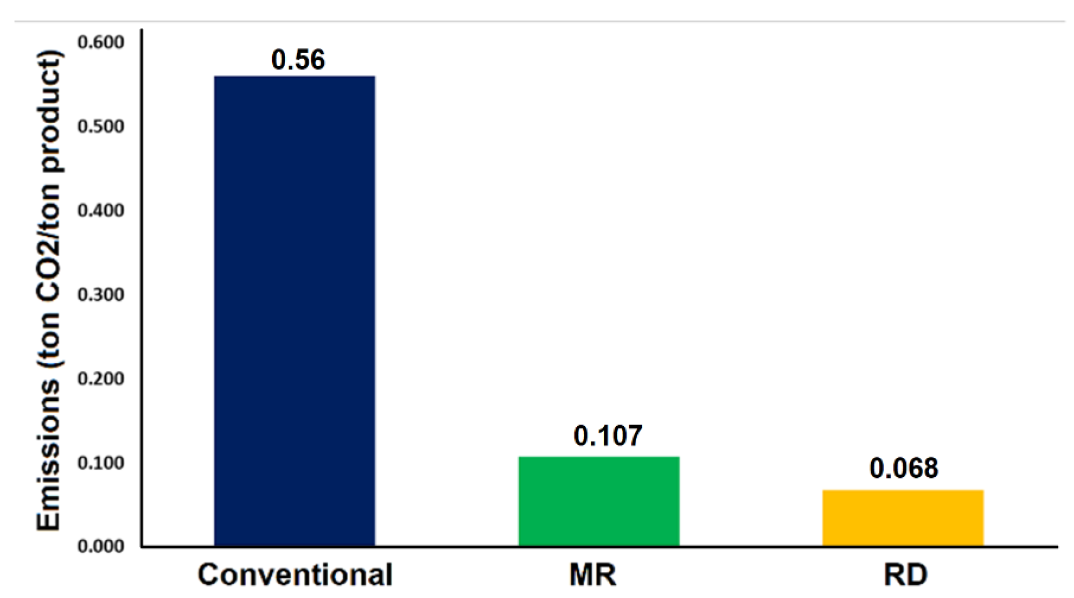
7.2. Environmental Analysis

An environmental assessment was conducted on the three distinct butyl acetate processes. The impact of the butyl acetate processes on the environment was evaluated based on CO2 emissions. It is assumed that steam is generated using natural gas, and the CO2 emitted from the butyl acetate process is mainly produced by the process of steam consumption. The Aspen Plus Environmental Analyzer was used to calculate the amount of CO2 emitted from the three distinctive processes. The Aspen software determines the amount of generated CO2 based on the fuel type. In this study, natural gas (NG) was used for all processes as a source of energy.
Figure 18 shows the emitted CO2 per butyl acetate produced, and the conventional process shows the highest CO2 emission compared to the MR and RD processes. This is due to the high steam required by the conventional process.

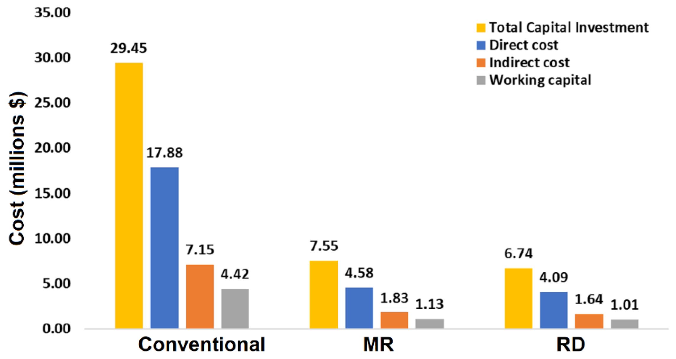
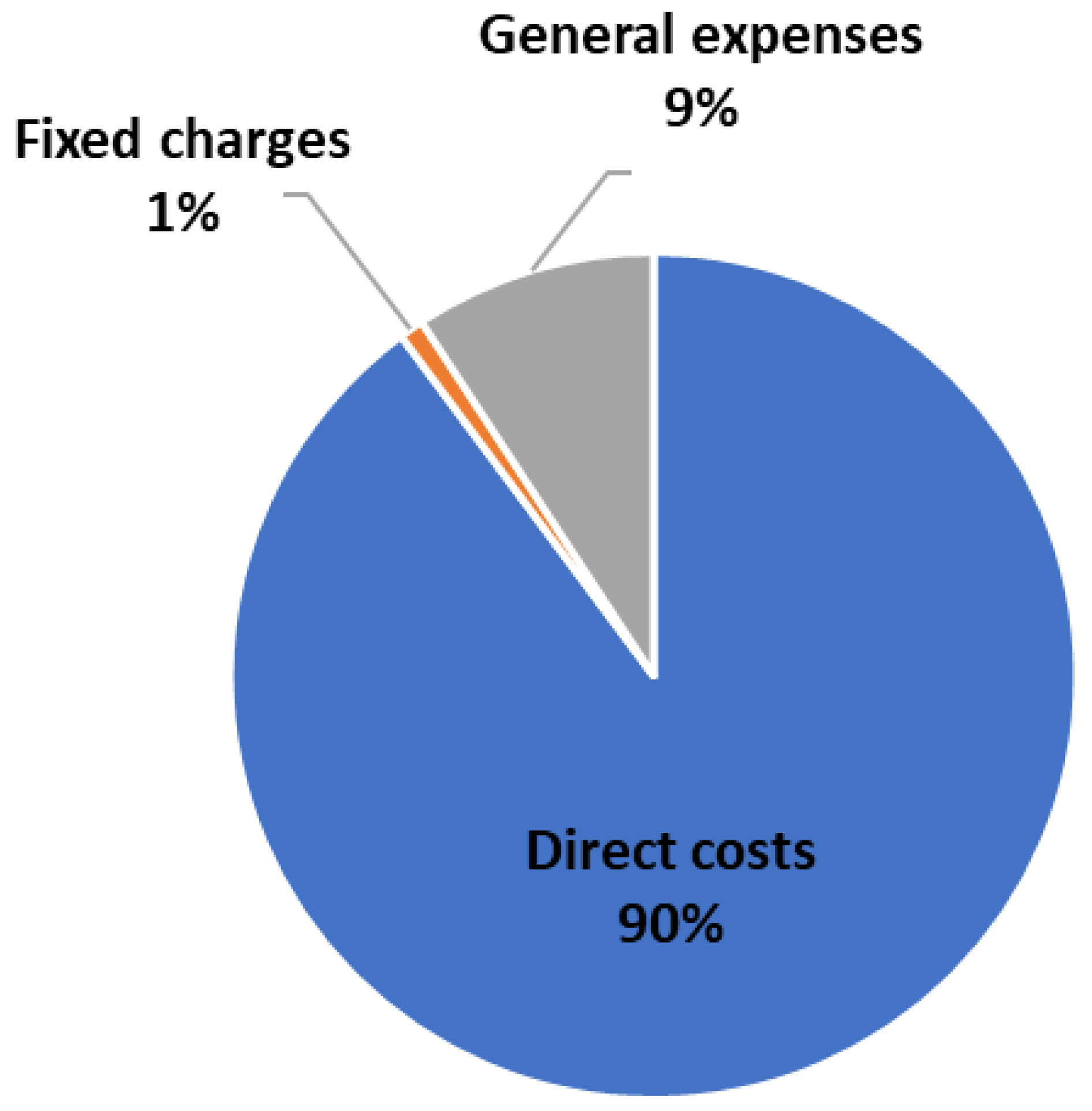
8. Economic Analysis

An economic analysis was conducted for the membrane reactor, conventional and reactive distillation processes. The purchased equipment costs were determined using the Aspen Plus Economic Analyzer, and the Chemical Engineering Plant Cost Index (CEPI) of 2021 was used to update the equipment costs. Table 11 shows the prices of acetic acid, n-butanol, and butyl acetate, along with the prices of other utilities used for the process.
Figure 19 shows a comparison of direct costs, indirect costs, working capital, and total capital investment for the three processes. It was found that the total capital investment of the membrane reactor and reactive distillation processes is much lower compared to the conventional process. The separation of unreacted n-butanol and butyl acetate in the MR-based process is difficult and requires a distillation column with a larger number of stages. This ultimately increased the capital investment and operating costs compared to the RD process.
Table 12 shows an economic comparison between the MR and RD processes for butyl acetate production. The economic indicators show that the MR process has a return on investment (ROI) of 23.1% and a payback period of 2.7 years. However, the MR process is economically less attractive compared to the RD process because of the capital and energy-intensive distillation column used for the separation of n-butanol and acetic acid from the product.
Figure 20 shows the cost distribution of the total production costs (TPC) for the MR-based process. The raw materials are responsible for around 87% of the TPC. Figure 21a,b show that the utility cost distributions of the MR and RD processes are similar.

9. Conclusions

A novel process based on a membrane reactor was designed for butyl acetate production. The membrane reactor was modeled and validated with the experimental data, and a good agreement was found. The MR-based process was developed and designed for an annual capacity of 92,500 metric tons of BuAc. The n-butanol conversion of MR, conventional, and RD processes was 92%, 69.8%, and 98%, respectively. The MR-based process is promising, economically feasible, and has less CO2 emissions than the conventional process. However, the MR-based process is slightly less profitable when compared to the RD process due to the intensive separation that follows the membrane reactor. If the conversion of n-butanol in the membrane reactor increases to more than 95%, the MR process will be more attractive than the RD process. Future research should focus on finding more selective catalysts that can be used with the membrane for butyl acetate production.

Author Contributions

Conceptualization, A.A.A.-R.; methodology, A.A.A.-R. and A.E.A.; software, A.A.A.-R., A.E.A. and R.K.A.D.; validation, A.E.A., R.K.A.D. and A.A.A.-R.; formal analysis, A.A.A.-R., A.E.A., R.K.A.D. and A.S.B.N.; investigation, A.A.A.-R., A.E.A., R.K.A.D. and A.S.B.N.; resources, A.E.A. and A.A.A.-R.; data curation, A.E.A. and A.A.A.-R.; writing—original draft preparation, A.A.A.-R. and A.E.A.; writing—review and editing, A.A.A.-R. and A.E.A.; supervision, A.A.A.-R.; project administration, A.A.A.-R.; funding acquisition, A.A.A.-R. All authors have read and agreed to the published version of the manuscript.

Funding

This project was supported by King Saud University, Deanship of Scientific Research, College of Engineering Research Center.

Institutional Review Board Statement

Not applicable.

Informed Consent Statement

Not applicable.

Data Availability Statement

Not applicable.

Conflicts of Interest

The authors declare no conflict of interest.

References

  1. Arpornwichanop, A.; Koomsup, K.; Assabumrungrat, S. Hybrid Reactive Distillation Systems for N-Butyl Acetate Production from Dilute Acetic Acid. J. Ind. Eng. Chem. 2008, 14, 796–803. [Google Scholar] [CrossRef]
  2. Steinigeweg, S.; Gmehling, J. N-Butyl Acetate Synthesis via Reactive Distillation: Thermodynamic Aspects, Reaction Kinetics, Pilot-Plant Experiments, and Simulation Studies. Ind. Eng. Chem. Res. 2002, 41, 5483–5490. [Google Scholar] [CrossRef]
  3. Tian, H.; Zhao, S.; Zheng, H.; Huang, Z. Optimization of Coproduction of Ethyl Acetate and N-Butyl Acetate by Reactive Distillation. Chin. J. Chem. Eng. 2015, 23, 667–674. [Google Scholar] [CrossRef]
  4. Sato, T.; Nagasawa, H.; Kanezashi, M.; Tsuru, T. Enhanced Production of Butyl Acetate via Methanol-Extracting Transesterification Membrane Reactors Using Organosilica Membrane: Experiment and Modeling. Chem. Eng. J. 2022, 429, 132188. [Google Scholar] [CrossRef]
  5. Fang, D.; Wen, Z.; Lu, M.; Li, A.; Ma, Y.; Tao, Y.; Jin, M. Metabolic and Process Engineering of Clostridium Beijerinckii for Butyl Acetate Production in One Step. J. Agric. Food Chem. 2020, 68, 9475–9487. [Google Scholar] [CrossRef]
  6. Cao, X.; Ren, J.; Xu, C.; Zhang, K.; Zhan, C.; Lan, J. Preparation, Characterization of Dawson-Type Heteropoly Acid Cerium (III) Salt and Its Catalytic Performance on the Synthesis of n-Butyl Acetate. Chin. J. Chem. Eng. 2013, 21, 500–506. [Google Scholar] [CrossRef]
  7. Ben Salah, R.; Ghamghui, H.; Miled, N.; Mejdoub, H.; Gargouri, Y. Production of Butyl Acetate Ester by Lipase from Novel Strain of Rhizopus Oryzae. J. Biosci. Bioeng. 2007, 103, 368–372. [Google Scholar] [CrossRef] [PubMed]
  8. Hanika, J.; Kolena, J.; Smejkal, Q. Butylacetate via Reactive Distillation—Modelling and Experiment. Chem. Eng. Sci. 1999, 54, 5205–5209. [Google Scholar] [CrossRef]
  9. Peters, T.A.; Benes, N.E.; Holmen, A.; Keurentjes, J.T.F. Comparison of Commercial Solid Acid Catalysts for the Esterification of Acetic Acid with Butanol. Appl. Catal. A Gen. 2006, 297, 182–188. [Google Scholar] [CrossRef]
  10. Blagov, S.; Parada, S.; Bailer, O.; Moritz, P.; Lam, D.; Weinand, R.; Hasse, H. Influence of Ion-Exchange Resin Catalysts on Side Reactions of the Esterification of n-Butanol with Acetic Acid. Chem. Eng. Sci. 2006, 61, 753–765. [Google Scholar] [CrossRef]
  11. Gangadwala, J.; Mankar, S.; Mahajani, S.; Kienle, A.; Stein, E. Esterification of Acetic Acid with Butanol in the Presence of Ion-Exchange Resins as Catalysts. Ind. Eng. Chem. Res. 2003, 42, 2146–2155. [Google Scholar] [CrossRef]
  12. Abashar, M.E.E.; Al-Rabiah, A.A. Production of Ethylene and Cyclohexane in a Catalytic Membrane Reactor. Chem. Eng. Process. Process Intensif. 2005, 44, 1188–1196. [Google Scholar] [CrossRef]
  13. Bin Naqyah, A.S.; Al-Rabiah, A.A. Development and Intensification of the Ethylene Process Utilizing a Catalytic Membrane Reactor. ACS Omega 2022, 7, 28445–28458. [Google Scholar] [CrossRef]
  14. Liu, G.; Guo, S.; He, B.; Li, J.; Qian, X. Synthesis of Butyl Acetate in a Membrane Reactor in a Flow-Through Mode. Int. J. Chem. React. Eng. 2016, 14, 579–585. [Google Scholar] [CrossRef]
  15. Liu, Q.; Zhang, Z.; Chen, H. Study on the Coupling of Esterification with Pervaporation. J. Memb. Sci. 2001, 182, 173–181. [Google Scholar] [CrossRef]
  16. Khajavi, S.; Jansen, J.C.; Kapteijn, F. Application of a Sodalite Membrane Reactor in Esterification—Coupling Reaction and Separation. Catal. Today 2010, 156, 132–139. [Google Scholar] [CrossRef]
  17. de la Iglesia, Ó.; Mallada, R.; Menéndez, M.; Coronas, J. Continuous Zeolite Membrane Reactor for Esterification of Ethanol and Acetic Acid. Chem. Eng. J. 2007, 131, 35–39. [Google Scholar] [CrossRef]
  18. Tanaka, K.; Yoshikawa, R.; Ying, C.; Kita, H.; Okamoto, K. Application of Zeolite Membranes to Esterification Reactions. Catal. Today 2001, 67, 121–125. [Google Scholar] [CrossRef]
  19. Jafar, J.J.; Budd, P.M.; Hughes, R. Enhancement of Esterification Reaction Yield Using Zeolite A Vapour Permeation Membrane. J. Memb. Sci. 2002, 199, 117–123. [Google Scholar] [CrossRef]
  20. Shen, Y.; Zhao, F.; Qiu, X.; Zhang, H.; Yao, D.; Wang, S.; Zhu, Z.; Yang, J.; Cui, P.; Wang, Y.; et al. Economic, Thermodynamic, and Environmental Analysis and Comparison of the Synthesis Process of Butyl Acetate. Ind. Eng. Chem. Res. 2020, 59, 21869–21881. [Google Scholar] [CrossRef]
  21. Liu, K.; Tong, Z.; Liu, L.; Feng, X. Separation of Organic Compounds from Water by Pervaporation in the Production of N-Butyl Acetate via Esterification by Reactive Distillation. J. Memb. Sci. 2005, 256, 193–201. [Google Scholar] [CrossRef]
  22. Tian, H.; Huang, Z.; Qiu, T.; Wang, X.; Wu, Y. Reactive Distillation for Producing N-Butyl Acetate: Experiment and Simulation. Chin. J. Chem. Eng. 2012, 20, 980–987. [Google Scholar] [CrossRef]
  23. Luyben, W.L.; Yu, C.C. Reactive Distillation Design and Control; John Wiley & Sons: Hoboken, NJ, USA, 2009. [Google Scholar]
  24. Gangadwala, J.; Kienle, A.; Stein, E.; Mahajani, S. Production of Butyl Acetate by Catalytic Distillation: Process Design Studies. Ind. Eng. Chem. Res. 2004, 43, 136–143. [Google Scholar] [CrossRef]
  25. Taylor, R.; Krishna, R. Modelling Reactive Distillation. Chem. Eng. Sci. 2000, 55, 5183–5229. [Google Scholar] [CrossRef]
  26. Chemanalyst. 2022. Available online: https://www.chemanalyst.com/ (accessed on 2 May 2022).
Figure 1. Equilibrium conversion of n-butanol vs. reaction temperature for the esterification reaction.
Processes 10 01801 g001
Figure 2. Residue curves map of the water-n-butanol-1,4-butanediol mixture at a pressure of 101.3 kPa.
Processes 10 01801 g002
Figure 3. Components concentration as a function of the residence time of the membrane reactor.
Processes 10 01801 g003
Figure 4. Variation of concentration results of mathematical model vs. experimental.
Processes 10 01801 g004
Figure 5. n-Butanol conversion as a function of (a) the residence time of the membrane reactor and (b) acetic acid/n-butanol feed ratio.
Processes 10 01801 g005
Figure 6. Components flow rates as a function of the length of the membrane reactor.
Processes 10 01801 g006
Figure 7. n-Butanol conversion as a function of the length of the membrane reactor.
Processes 10 01801 g007
Figure 8. Process flow diagram (PFD) of butyl acetate production using a membrane reactor.
Processes 10 01801 g008
Figure 9. Equilibrium x-y diagram of n-butanol/butyl acetate mixture at: (a) 101 kPa and (b) 304 kPa.
Processes 10 01801 g009
Figure 10. Liquid-phase molar compositions of components inside the extractive distillation column as a function of stage number.
Processes 10 01801 g010
Figure 11. Conventional process flow diagram (PFD) for n-butanol esterification with acetic acid.
Processes 10 01801 g011
Figure 12. Components flowrates as a function of reactor length using the kinetic model.
Processes 10 01801 g012
Figure 13. n-butanol conversion as a function of temperature for the esterification process.
Processes 10 01801 g013
Figure 14. n-butanol conversion as a function of reactor length.
Processes 10 01801 g014
Figure 15. Liquid-phase molar compositions of components inside the extractive distillation column as a function of stage number.
Processes 10 01801 g015
Figure 16. n-Butanol esterification with acetic acid by reactive distillation process.
Processes 10 01801 g016
Figure 17. (a) The liquid-phase molar compositions of components as a function of stage number. (b) Temperature profile inside the reactive distillation column as a function of stage number.
Processes 10 01801 g017
Figure 18. CO2 emissions per product for the three processes.
Processes 10 01801 g018
Figure 19. Economic comparisons of the three processes for n-butanol esterification with acetic acid.
Processes 10 01801 g019
Figure 20. Cost distribution of the total production costs (TPC) of the process MR-based process.
Processes 10 01801 g020
Figure 21. Annual utilities cost distribution of (a) MR-based process and (b) RD-based process.
Processes 10 01801 g021
Table 1. Membrane reactor model parameters.
MR Model Parameters
BuOH flowrate100 (kmol/h)
AA flowrate100 (kmol/h)
Reactor length8 m
Membrane effective surface area
MR cross sectional area
100 m2
12.5 m2
Permeability coefficient of water (PW)0.00148 (m−2·h−1)
Table 2. Model results and experimental data using MR for BuAc production.
SampleConversion (%)Relative Deviation (%)
Experimental Results [16]Model Results
178.67580.752.637
286.12585.5−0.725
389.12587.875−1.403
490.37589.125−1.383
Table 3. Reactor design specifications for the membrane reactor process.
Membrane Reactor Specification
BuOH to AA feed ratio1:1
Temperature363 K
Reactor pressure284 kPa
Membrane surface area
Catalyst
100 m2
Amberlyst-15
Table 4. Stream information of the MR-based process for n-butanol esterification with acetic acid.
Stream1234
Temperature (K)298.2298.2311362.1
Pressure (kPa)111111304304
Enthalpy (kW)−12,825−9129−24,042−16,529
Molar vapor fraction0000
Mass flow (kg/h)6065741214,82513,010
Component Flowrates in (kmol/h)
Butanol0100108.698.69
Acetic acid1010110.1210.12
Butyl-acetate001.18101.07
Water001.011.01
Stream567W
Temperature (K)422.4444.9313.2362
Pressure (kPa)2843.2132223
Enthalpy (kW)−2090−13,756−14,727−7818
Molar vapor fraction0000
Mass flow (kg/h)134711,66311,6631814
Component Flowrates in (kmol/h)
Butanol8.69000.01
Acetic acid9.12110.01
Butyl-acetate1.1899.8999.890.1
Water1.010099.99
Table 5. Major equipment parameters summary for the MR-based process.
EquipmentParameterSpecifications
Membrane Reactor R-101 Volume
Length
Heat duty
Temperature
Pressure
Acetic acid/n-butanol
100 m3
8 m
−286 kW
363 K
223 kPa
1:1
Distillation column T-101 Number of stages
Feed stage
Reboiler heat duty
Condenser heat duty
Distillate rate
Bottoms rate
42 stages
21
5208 kW
−4526 kW
20 kmol/h
100.9 kmol/h
Heat exchanger E-101 Heat duty
Outlet temperature
Outlet pressure
−970 kW
313 K
132 kPa
P-101 Discharge pressure
Head
Fluid power
304 kPa
11 m
0.92 kW
P-102 Discharge pressure
Head
Fluid power
304 kPa
23 m
0.36 kW
Table 6. Reactor design specifications for the conventional process.
Conventional Reactor Specifications
BuOH-to-AA feed ratio1:1
Temperature363 K
Feed pressure284 kPa
Volume41 m3
CatalystAmberlyst-15
Table 7. Streams information on the conventional process for n-butanol esterification with acetic acid.
Stream1234567
Temperature (K)298.2298.2298.2363.3411.1444.9308.2
Pressure (kPa)111111111304284324132
Enthalpy (kW)−18,158−13,054−31,212−31,138−14,805−13,641−14,639
Molar vapor fraction0000100
Mass flow (kg/h)6059741719,27819,278761011,66811,668
Component Flowrates in (kmol/h)
n-Butanol0.0100.1143.143.243.10.10.1
Acetic acid100.90.0142.742.841.81.01.0
Butyl-acetate0.00.00.9100.80.999.999.9
Water0.00.00.099.999.90.00.0
Solvent0.00.00.00.00.00.00.0
Stream891011121314
Temperature (K)298.2507.0373.1462.6393.6512.2303.2
Pressure (kPa)121121111142132142132
Enthalpy (kW)−54−55,646−7800−65,897−9060−55,592−61,735
Vapor mole fraction0000000
Mass flow (kg/h)3439,687184245,455580239,65339,653
Component Flowrates in (kmol/h)
n-Butanol0.00.00.143.043.00.00.0
Acetic acid0.00.00.041.841.80.00.0
Butyl-acetate0.00.00.00.90.90.00.0
Water0.00.099.90.00.00.00.0
Solvent0.4440.30.4439.90.0439.9439.9
Table 8. Reactor design specifications for the RD process.
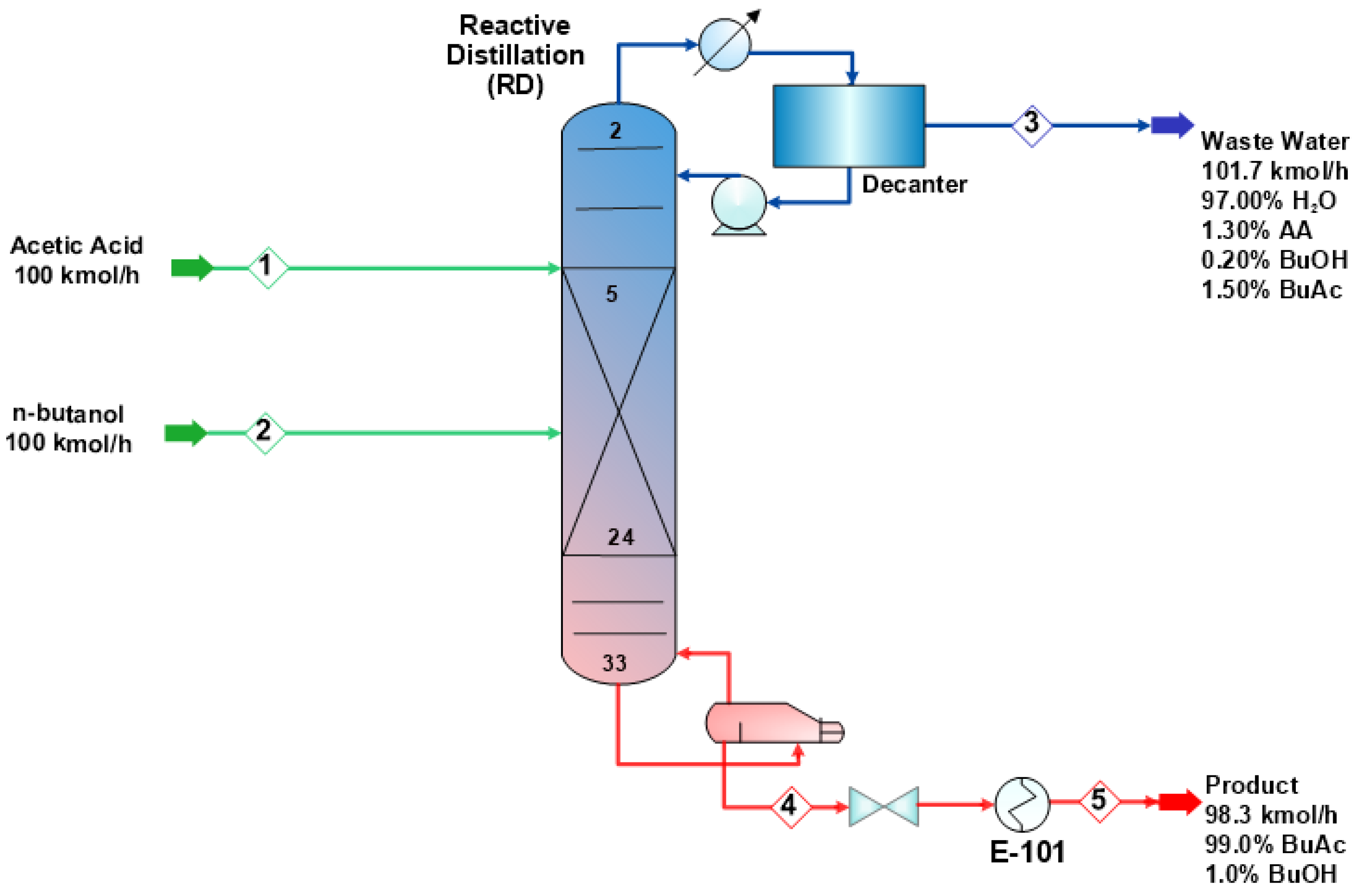
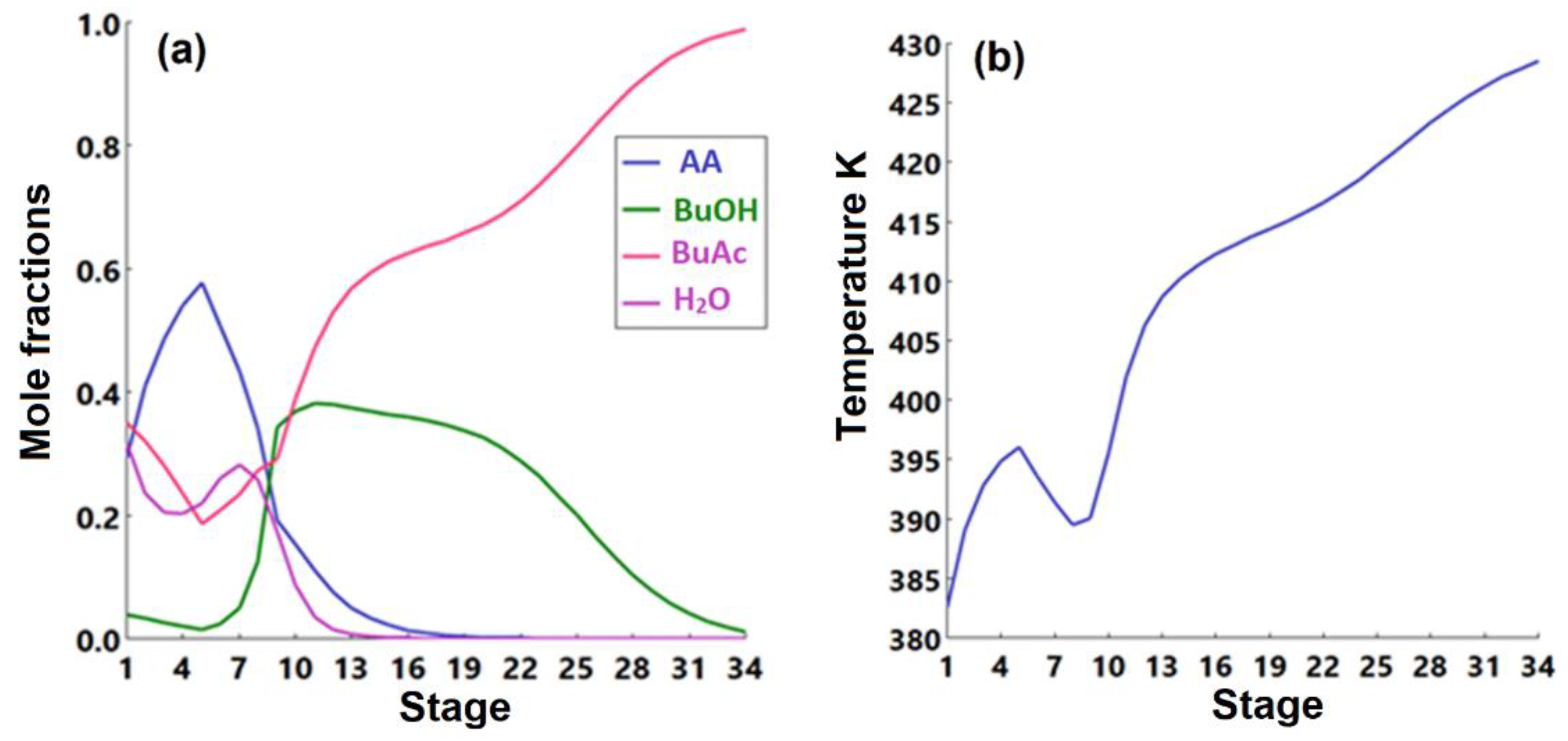
Reactive Distillation Design Specifications
Number of stages34
AA feed stage5
BuOH feed stage9
Reactive zone stages5–24
Reboiler duty3298 kW
Condenser duty−3010 kW
Table 9. Stream information of the reactive distillation-based process for n-butanol esterification with acetic acid.
Stream12345
Temperature (K)298.2298.2382.6428.5313.2
Pressure (kPa)203203152223132
Enthalpy (kW)−12,698−9129−8045−13,493−14,312
Molar vapor fraction00000
Mass flow (kg/h)60057412204011,37711,377
Component Flowrates in (kmol/h)
n-Butanol0.0100.00.21.11.1
Acetic acid100.00.01.30.00.0
Butyl-acetate0.00.01.597.297.2
Water0.00.098.70.00.0
Table 10. Required hot and cold utilities in the three esterification processes.
Utility (MWh/Year)ConventionalRDMR
Steam (mps)218,72926,38841,668
Cooling water215,50430,63843,973
Table 11. Raw materials, products, and utility costs for the esterification process [23,26].
UnitPrice
Acetic Acid (USD/ton)960
n-Butanol (USD/ton)1610
Butyl Acetate (USD/ton)2120
Utilities
Steam (mps) (USD/ton)6
Cooling water (USD/m3)0.53
Wastewater treatment (USD/m3)0.08
Table 12. Economic comparisons between the MR process and RD process for butyl acetate production.
ItemMRRD
Fixed capital costUSD 6,418,000USD 5,730,000
Total capital costUSD 7,552,000USD 6,742,000
Return on investment23.1%31.17%
Payback period2.72.1
Net present valueUSD 13,670,000USD 15,857,000
Publisher’s Note: MDPI stays neutral with regard to jurisdictional claims in published maps and institutional affiliations.

