
The Influence of the Fusion State of the Particles during the Simultaneous Impact on an Oxidized Substrate in the Presence of Asperities


Abstract
:1. Introduction
2. Modeling
2.1. The Continuity Equation
2.2. The Momentum Equation
2.3. Two-Phase Liquid/Solid Modeling
2.4. Thermal Model
2.5. The Thermal Model Used
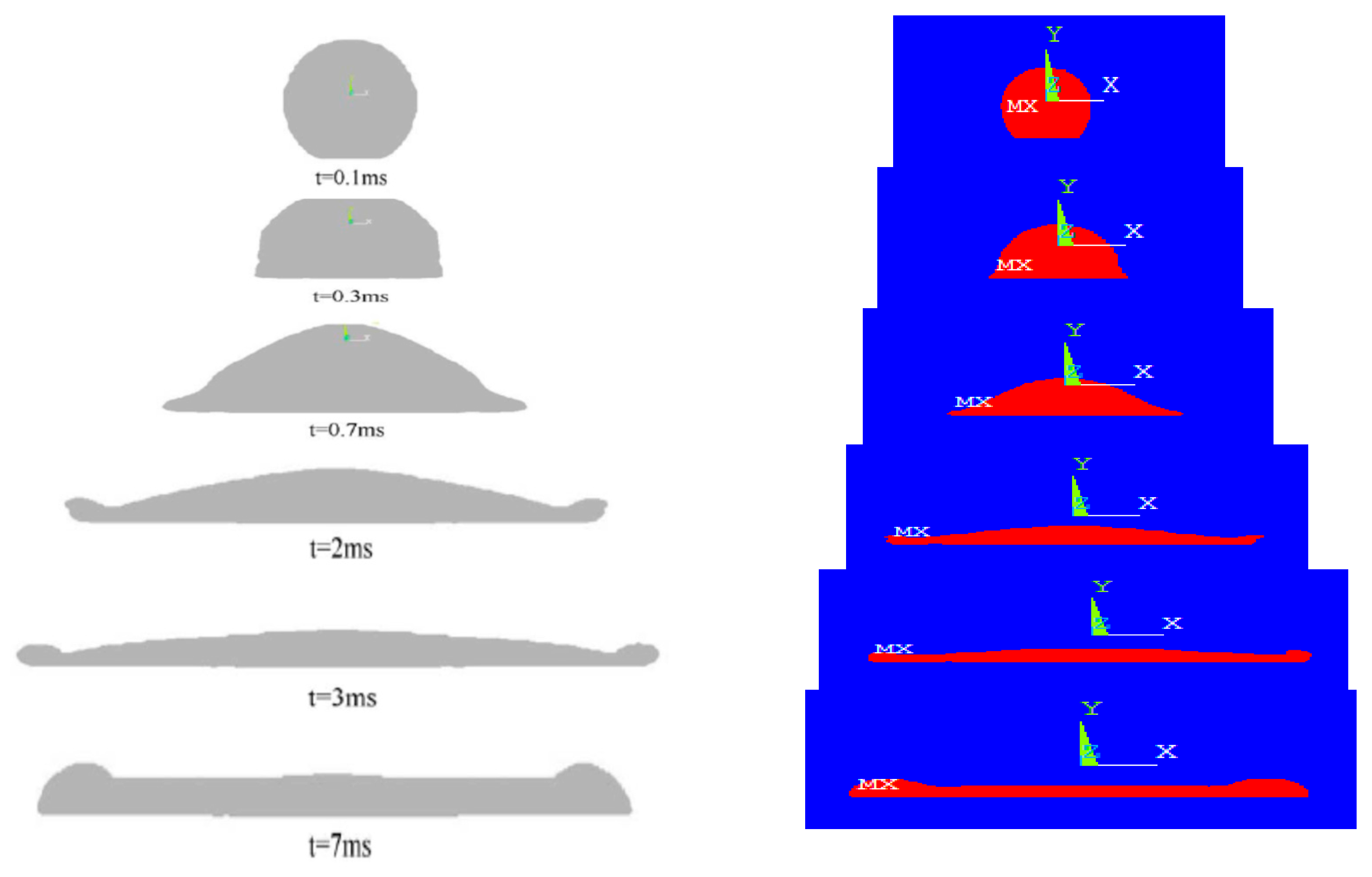
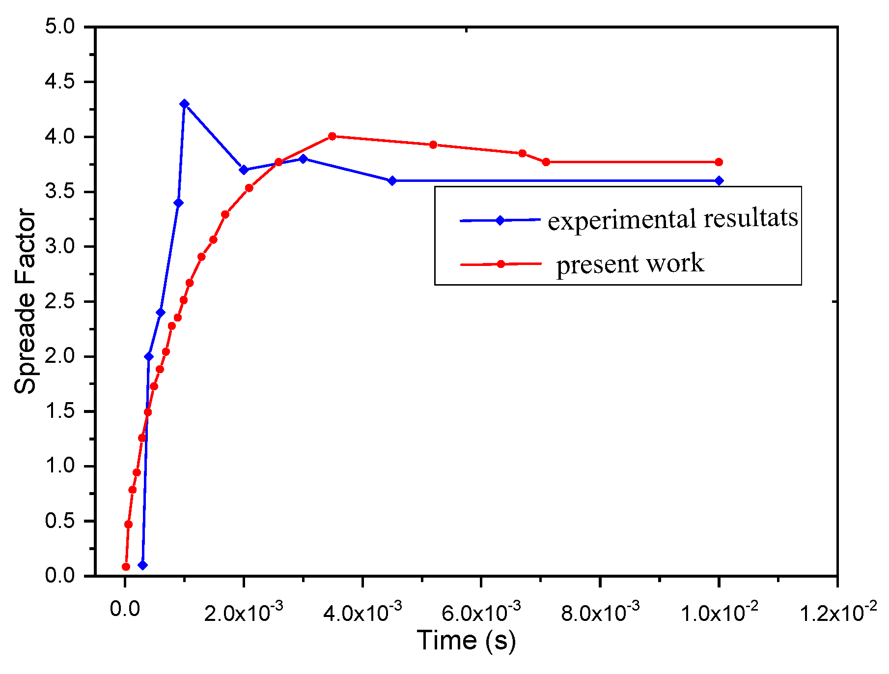
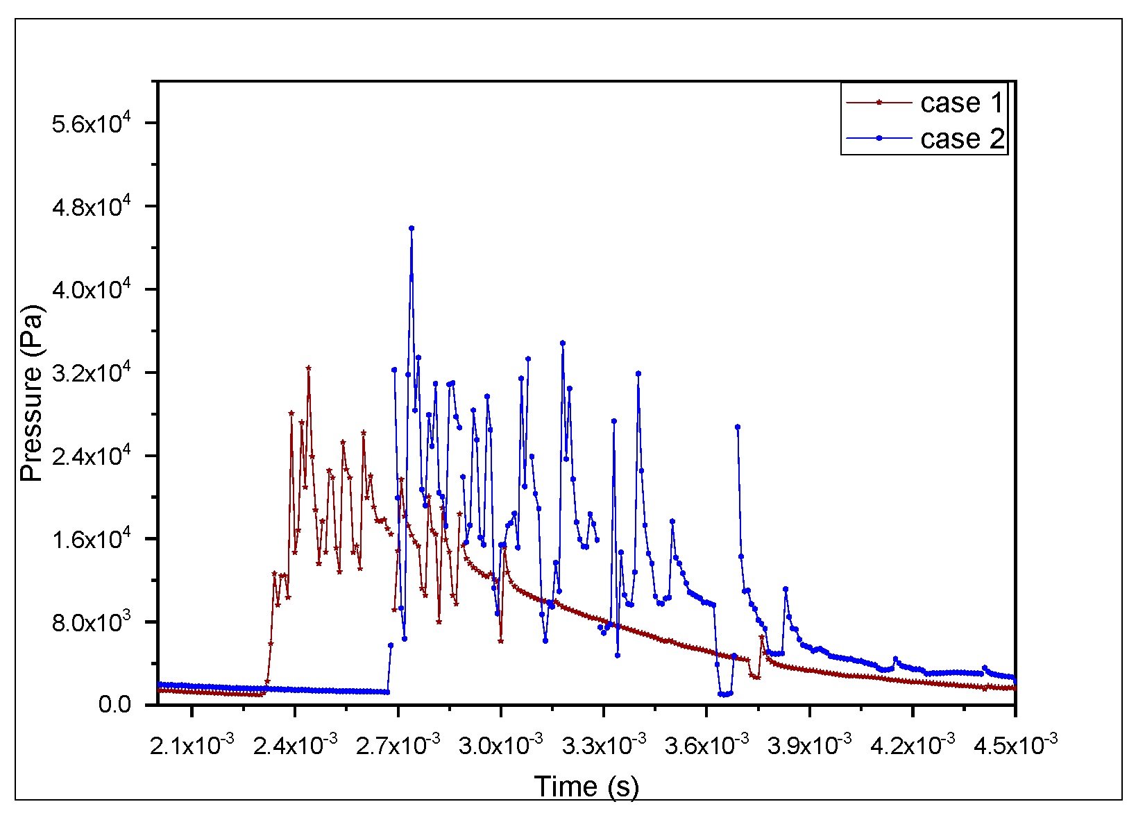
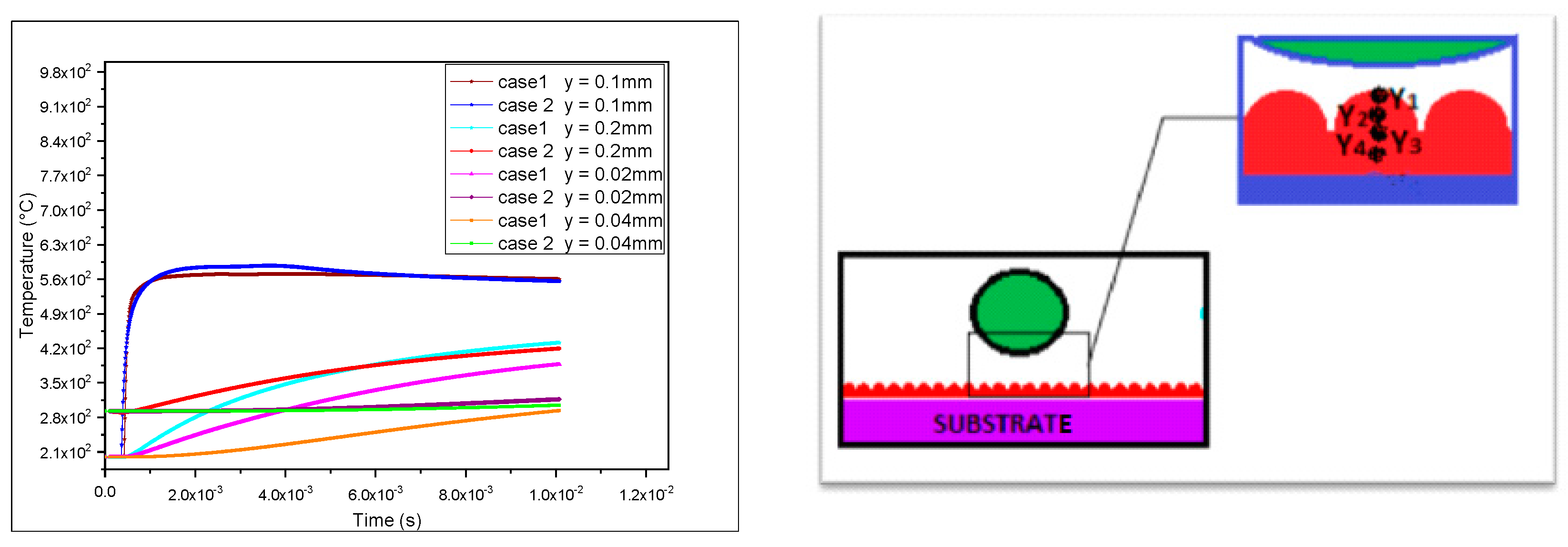
3. Results and Discussions
3.1. Identification
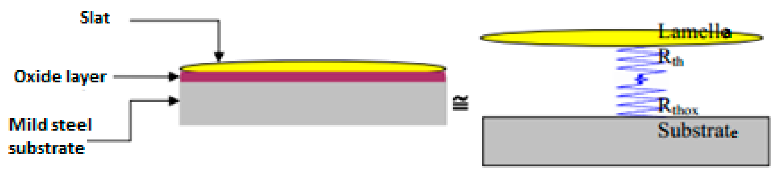
3.2. Oxidation of the Surface of Metal Substrates
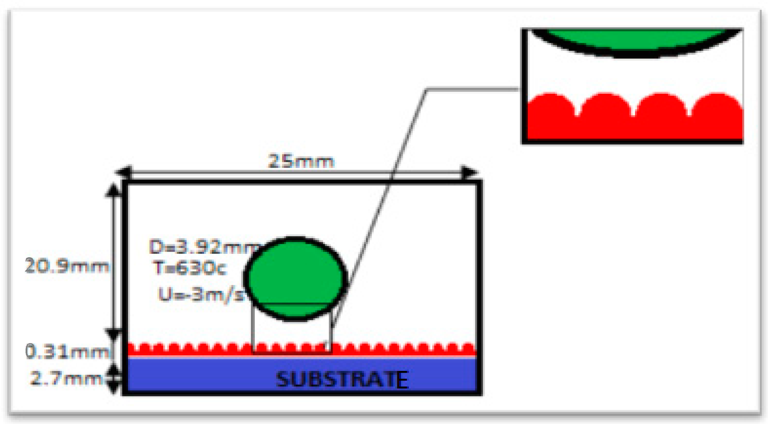
3.2.1. Configuration and Spreading Conditions with an Oxidation Layer
- The initial temperature of the droplet considering an aluminum particle t = 630 °C.
- The initial temperature of the substrate T = 200 °C.
- Speed of the 3 m/s droplet.
3.2.2. Description of the Field of Application
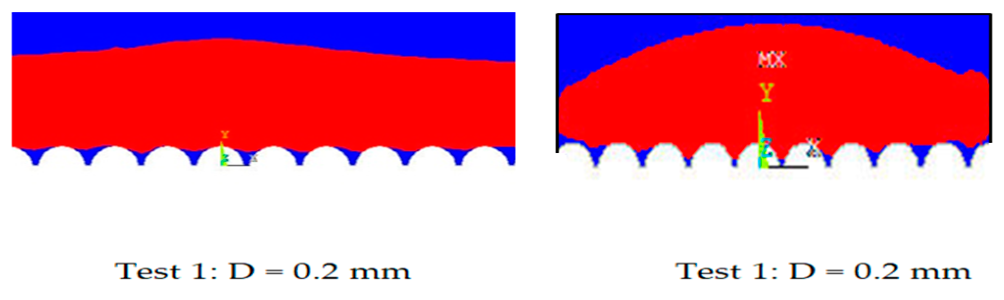
3.2.3. Different Pick Sizes
4. Conclusions
- ➢
- The adherence of the particle to the substrate determined its impact pressure, which was why the pressure that the particles produced was rather high.
- ➢
- There was a larger pressure at the place of impact (under the sipe), which led to good adhesion. The diameter of the peaks had a significant impact on adhesion, which in turn affected the final shape of the lamella formation.
- ➢
- The asperities at the level of the lamella–substrate contact were important, taking into account the oxide layer that formed automatically on the surface of metal substrates during preheating.
Author Contributions
Funding
Institutional Review Board Statement
Informed Consent Statement
Data Availability Statement
Conflicts of Interest
References
- Sobolev, V.V.; Guilemany, J.M. Effect of oxidation on droplet flattening and splat-substrate interaction in thermal spraying. J. Therm. Spray Technol. 1999, 8, 523–530. [Google Scholar] [CrossRef]
- Xue, M.; Heichal, Y.; Chandra, S.; Mostaghimi, J. Modeling the impact of a mol-ten metal droplet on a solid surface using variable interfacial thermal contact resistance. J. Mater. Sci. 2007, 42, 9–18. [Google Scholar] [CrossRef] [Green Version]
- Chandra, S.; Fauchais, P. Formation of solid splats during thermal spray deposition. J. Therm. Spray Technol. 2009, 18, 148–180. [Google Scholar] [CrossRef]
- Ortega-Casanova, J.; Granados-Ortiz, F.J. Numerical simulation of the heat transfer from a heated plate with surface variations to an impinging jet. Int. J. Heat Mass Transf. 2014, 76, 128–143. [Google Scholar] [CrossRef]
- Alavi, S.; Passandideh-Fard, M.; Mostaghimi, J. Simulation of semi-molten particle impacts including heat transfer and phase change. J. Therm. Spray Technol. 2012, 21, 1278–1293. [Google Scholar] [CrossRef]
- Zirari, M.; Abdellah El-Hadj, A.; Bacha, N. Numerical analysis of partially molten splat during thermal spray process using the finite element method. Appl. Surf. Sci. 2010, 256, 3581–3585. [Google Scholar] [CrossRef]
- Tahar, S.; Zirari, M.; Benzerdjeb, A.; Hanini, S. Numerical simulation EF/VOF to study the influence of the surface condition of the formation of the slats of a nickel deposit produced by plasma spraying. Ann. Chim. Sci. Matériaux 2018, 42, 165–180. [Google Scholar]
- Abdellah El-Hadj, A.; Zirari, M.; Bacha, N. Numerical analysis of the effect of the gas temperature on splat formation during thermal spray process. Appl. Surf. Sci. 2011, 257, 1643–1648. [Google Scholar] [CrossRef]
- Zirari, M.; Tahar, S.; Chandra, S.; Bacha, N. Numerical analysis of the dynamics and the rapid solidification on splat formation during thermal spray process using the finite element method. In Proceedings of the 21ème Congrès Français de Mécanique, Bordeaux, France, 26–30 August 2013. [Google Scholar]
- Ghafouri-Azar, R.; Mostaghimi, J.; Chandra, S.; Charmchi, M. A stochastic model to simulate the formation of a thermal spray coating. J. Therm. Spray Technol. 2003, 12, 53–69. [Google Scholar] [CrossRef]
- Voller, V.R. Fast implicit finite-difference method for the analysis of phase change problems. Numer. Heat Transf. 1990, 17, 155–169. [Google Scholar] [CrossRef]
- Shinde, S.S.; Bansode, R.A.; Bhosale, C.H.; Rajpure, K.Y. Physical properties of hematite α-Fe2O3 thin films: Application to photoelectrochemical solar cells. J. Semicond. 2011, 32, 013001. [Google Scholar] [CrossRef]
- Maitre, A.; Denoirjean, A.; Fauchaisb, P.; Lefortb, P. Plasma-jet coating of preoxidized XC38 steel: Influence of the nature of the oxide layer. J. Phys. Chem. Chem. Phys. 2002, 4, 3887–3893. [Google Scholar] [CrossRef]
- Le Bot, C.; Vincent, S.; Meillot, E.; Sarret, F.; Caltagirone, J.P.; Bianchi, L. Numerical simulation of several impacting ceramic droplets with liquid/solid phase change. Surf. Coat. Technol. 2015, 268, 272–277. [Google Scholar] [CrossRef]


| Properties | Particle: Alumina | Substrate: Steel H13 | Fe2O3 Oxide Layer | ||
|---|---|---|---|---|---|
| Density (Kg/m³) | 2570 | 7800 | 5240 | ||
| Viscosity (liquid) (m²/s) | T °C | - | - | ||
| 0 | 105 | ||||
| 700 | 1.0345 × 10⁻³ | ||||
| Thermal conductivity (W/m K) | 70 | 26 | 2.9 | ||
| Liquid specific heat (J/Kg K) | 1000 | - | 670 | ||
| Solid thermal conductivity (W/m K) | T °C | - | - | ||
| 400 | 144 | ||||
| 500 | 147 | ||||
| 630 | 70 | ||||
| Specific heat (J/Kg K) | T °C | T °C | - | ||
| 100 | 400 | ||||
| 300 | 500 | 20 | 460 | ||
| 400 | 800 | 200 | 502 | ||
| 570 | 1050 | 500 | 550 | ||
| 580 | 1038 | ||||
| Case 1: D = 0.2 mm | Case 2: D = 0.4 mm | |||
|---|---|---|---|---|
| Volume Fraction | Temperature | Volume Fraction | Temperature | |
| t = 0.01 ms |  |  | 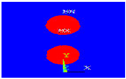 |  |
| t = 1 ms | 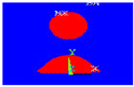 |  |  |  |
| t = 2 ms |  | 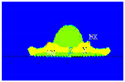 |  |  |
| t = 3 ms | 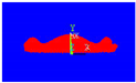 | 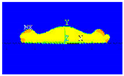 |  | 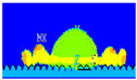 |
| t = 4 ms | 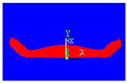 |  | 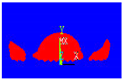 | 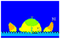 |
| t = 6 ms | 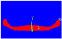 | 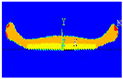 | 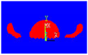 | 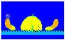 |
| t = 7 ms | 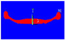 |  | 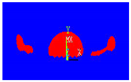 |  |
 | ||||
Publisher’s Note: MDPI stays neutral with regard to jurisdictional claims in published maps and institutional affiliations. |
© 2022 by the authors. Licensee MDPI, Basel, Switzerland. This article is an open access article distributed under the terms and conditions of the Creative Commons Attribution (CC BY) license (https://creativecommons.org/licenses/by/4.0/).
Share and Cite
Tahar, S.; Zirari, M.; Labbadlia, O.; Chiba, Y. The Influence of the Fusion State of the Particles during the Simultaneous Impact on an Oxidized Substrate in the Presence of Asperities. Processes 2022, 10, 1458. https://doi.org/10.3390/pr10081458
Tahar S, Zirari M, Labbadlia O, Chiba Y. The Influence of the Fusion State of the Particles during the Simultaneous Impact on an Oxidized Substrate in the Presence of Asperities. Processes. 2022; 10(8):1458. https://doi.org/10.3390/pr10081458
Chicago/Turabian StyleTahar, Souad, Mounir Zirari, Omar Labbadlia, and Younes Chiba. 2022. "The Influence of the Fusion State of the Particles during the Simultaneous Impact on an Oxidized Substrate in the Presence of Asperities" Processes 10, no. 8: 1458. https://doi.org/10.3390/pr10081458
APA StyleTahar, S., Zirari, M., Labbadlia, O., & Chiba, Y. (2022). The Influence of the Fusion State of the Particles during the Simultaneous Impact on an Oxidized Substrate in the Presence of Asperities. Processes, 10(8), 1458. https://doi.org/10.3390/pr10081458