1. Introduction
With increasing concerns regarding energy saving and greenhouse gas emissions, the process industries require better methods for the cost-effective retrofit of heat exchanger networks. [
1] Current retrofit strategies mainly concentrate on expanding the heat transfer area [
2] and using heat transfer enhancement technologies [
3]. However, energy savings are limited by the geometry of the heat exchangers and the availability of theoretical assets (mathematical models) to explore wider options when retrofitting [
4]. Thus, this research seeks to utilize high efficiency heat transfer equipment in the retrofit of HENs, namely Plate heat exchangers.
Plate heat exchangers, which are one of the most efficient types of heat transfer equipment [
5,
6], are considered in this research to provide an insight in the effect of the use of new heat transfer equipment in the minimization of the retrofit cost (and heat recovery). In comparison with conventional heat transfer equipment (e.g., shell-and-tube heat exchangers), the minimum approach temperature in PHEs is as low as 5 °C [
7], which can significantly enhance energy efficiency and decrease capital cost [
8]. However, there is no robust methodology to exploit effectively and to quantify the benefit of the use of such equipment. Moreover, the difference in minimum approach temperatures caused by the use of different heat transfer equipment poses an optimization problem at the network level. Therefore, to overcome the gaps mentioned above, this work will focus on developing a step-by-step methodology for the inclusion of different heat transfer equipment (namely PHEs and STHXs) in the retrofit of heat exchanger networks, which allows for network structural modifications, such as adding new heat exchangers, along with the splitting and resequencing of streams. The solution of the retrofit problem can be reached by deploying more than once approach. A suitable selection of this approach mainly depends on computational power and the fundamental view of the problem itself (e.g., from a thermodynamic or numerical perspective).
Pinch analysis, optimization and hybrid methods are regarded as the three general conventional methodologies for HEN retrofits [
9]. Pinch analysis was first implemented to retrofit of heat exchanger networks by Tjoe and Linhoff [
10]. The result of this analysis ensures that the heat recovery targets are met during design stages. These results can also be obtained when performing retrofit. To achieve the possible maximum heat recovery, the proposed approach identified those units exchanging heat across the pinch (which is thermodynamically infeasible) and redesigned the network to remove this behavior. A systematic method that eliminates cross-pinch heat transfer and re-locates the heat load based on the pinch analysis was later proposed by Li and Chang [
11]. The limitation of this pinch analysis-based approach was that it relies on an experienced user when it comes to large scale networks, since the methodology fails to point out the specific number of steps for modifications and the exact place for adding heat transfer area.
Optimization can be used to convert the retrofit problem into a mathematical programming model and solve such problem for different objectives [
12]. In the past few years, most of the researchers have been sought to develop stage-wise superstructure for heat exchanger network synthesis [
13]. A HEN synthesis using a stagewise superstructure with non-isothermal mixing was proposed by Huang et al. [
14]. In 2018, Pavão et al. [
15] considered substages, sub-splits and cross flows in the HEN retrofit when developing a stagewise superstructure. This work is further extended by Liu et al. [
16]. The network topology can also be modified by introducing a matrix representation [
17,
18,
19,
20]. Based on the complexity of the retrofit problem, the optimization model can be formulated as linear programming (LP), non-linear programming (NLP), and mixed integer linear programming (MILP) or mixed integer non-linear programming (MINLP). Among these, HEN retrofit is generally handled as a MINLP problem, where this type of approach was first developed by Yee et al. [
21]. This approach provides numerical advantages compared to the single use of pinch analysis; however, how to find a global optimum solution and how to simplify the model to perform fast and accurate estimations are the two main challenges around MINLP models [
22,
23]. Although the retrofit process is fully automated by formulating a mathematical model without relying on expert users, it is still difficult to avoid locally optimal solutions and prolonged computation workload with results that are sensitive to the assumptions.
The network pinch approach, proposed by Asante and Zhu [
24] to retrofit HENs, combines pinch analysis and numerical optimization methods, while keeping the individual advantages of both methods. This approach, which allows user interaction while ensuring a good retrofit design, involves two stages: diagnosis and optimization. The diagnosis stage analyses potential topology changes to achieve minimum energy consumption, subject to a fixed minimum approach temperature through a MILP model. In the second optimization stage, the trade-off between capital cost and energy saving is optimized by developing an NLP model to select the desired modifications. Smith et al. [
25] further modified the network pinch approach and combined topology changes and energy-capital trade-off optimization into a single step. However, this work still fails to identify the underlying reason for why the selected retrofit option is better than others, which may lead to inappropriate decisions.
Although the network pinch approach can be applied widely in retrofit problems, few research attempts have pointed out the reasons why the modifications choices are made. There has not been much investigation into why a modification option is better than another in terms of energy recovery. So far, most of these modification options are centered on resequencing, adding shell and tube heat exchangers and stream splitting. To the authors’ knowledge, no other work has sought utilization of different types of heat transfer equipment in the HENs retrofit problem and quantify the potential benefit in terms of energy savings and economic payback.
Therefore, to fill the gaps mentioned above, this work proposes an automated step-by-step approach to the HEN retrofit, considering the use of different types of heat exchangers. The key significance of this work is to integrate the high efficiency of PHEs into the optimization process, especially when it comes to dealing with different minimum approach temperatures for different heat transfer equipment. To quantify the potential benefit to apply PHEs, the economic cost for retrofit is calculated by employing different retrofit techniques. This work also provides guidelines on how to identify the most suitable retrofit changes, together with where and why to apply these changes under different scenarios in an automated fashion. In addition to current options such as adding new PHEs, resequencing and stream splitting are considered as further modification options for retrofit. The early identification of favorable topology changes provides a more robust result and saves both design and calculation time. The best retrofit design should maximize heat recovery while minimizing the cost, including equipment pipework and civil engineering. To provide adequate basis for applicability-oriented decisions that focuses on profit and energy saving, three case studies are presented to illustrate the effectiveness of the proposed method. To quantify the potential economic and energy benefits of the use of PHEs, the payback is used to compare between a network with only shell-and-tube heat exchangers (e.g., a conventional network), and a network with both types of heat exchangers.
2. Network Pinch
For existing HENs, pinching the network means to identify the possibilities to reduce energy consumption by exploiting the degrees of freedom within the network structure. These degrees of freedom are the utility paths and loops in the HEN. The connection between hot and cold utilities through process exchangers is named a utility path. Those paths that start and finish on the same heat exchanger are called loops. Redistributing the heat load in these loops can increase the driving force in the process exchangers, which reduces the utility consumption through the path [
26].
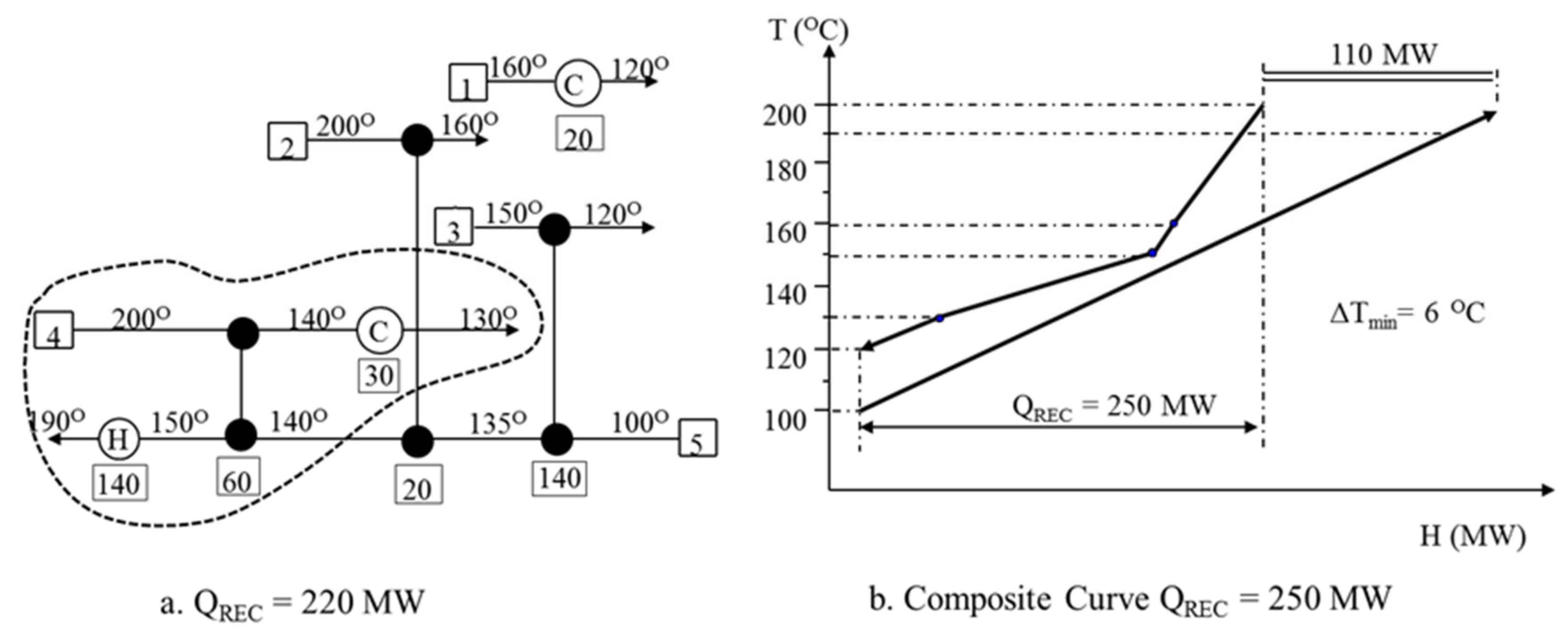
For example,
Figure 1a shows an existing HEN with an energy recovery of 200 MW and a minimum temperature difference (Δ
Tmin) of 20 °C. The corresponding energy recovery based on the Composite Curves is obtained with a Δ
Tmin of 22.5 °C (
Figure 1b).
To reduce the energy consumption while maintaining the network structure, the only way possible is by exploiting the utility paths present in the existing network. The bubble overlaid on the HEN shown in
Figure 1a highlights the only degree of freedom of the existing network. It indicates the connection between the heater (H) and cooler (C) through a process heat exchanger. The matches outside of the bubble are constrained by the heat duties on individual streams. For the sake of illustration, the Δ
Tmin of the existing HEN is set to 0 °C. This corresponds to an increase in the energy recovery of 20 MW as shown in
Figure 2a. We can note that even by maximizing the energy recovery down to 0 °C, the energy performance is worse than the energy target obtained using the Composite Curves shown in
Figure 2b. The difference between both results for maximum energy recovery results from the fact that the existing HEN structure is not appropriate for maximum energy recovery.
From the network structure for maximum energy recovery based on a Δ
Tmin of 0 °C, the exchanger that limits the energy recovery based on the existing network is identified. This heat exchanger is referred to as the pinching match (
Figure 3a), and the point at which this occurs in the existing network is known as the network pinch. Note that this is still based on the minimum temperature difference of 0 °C. In practice, if the network pinch is being identified in the design phase, a practical Δ
Tmin of say 10 °C or 20 °C is used [
26]. The Composite Curves for the same energy recovery are shown in
Figure 3b.
The only way to overcome the network pinch is by performing structural modifications. Therefore, this paper proposes a methodology of HEN retrofit with structural modifications.
4. Retrofit Methodology
The objective of this methodology is to provide a step-by-step guideline for integrating different types of heat transfer equipment into the retrofit of HENs. The method allows for with the handling of different minimum approach temperature caused by the different types of heat transfer devices. The best retrofit strategy is the one that meets the retrofit target with the minimum number of structural modifications and cost. To achieve this, the modifications and technology used should be such that they ensure maximum energy recovery.
The methodology proposed in this work covers: (1) the identification of the best single modification for a given HEN based on energy recovery, (2) the identification of the best series of modifications (i.e., multiple modifications), (3) the use of high efficiency exchangers in place of the conventional shell and tube heat exchanger, and (4) the comparison of different retrofit methods.
4.1. Single Modification
Below is an outline of the proposed step-by-step approach to identify the best single modification for an existing HEN:
Step 1:Pinch the network and identify features restricting energy recovery
Pinching the existing HEN relative for the selected ∆Tmin identifies the HEN features responsible for restricting energy recovery. Through pinching the existing network, pinched exchangers are identified, together with cross-pinch heat exchangers, which are caused by inappropriate use of utilities and process-to-process heat exchangers. By reviewing the network, the locations of these exchangers are identified. By pinching the network, the existing structure is maintained while reducing the utility consumption.
Step 2:Review the identified network features and identify the best type of modification based on energy recovery
Once the network is pinched, the best structural modification can be identified based on the location of the cross-pinch and pinched exchangers. To overcome the network pinch and eliminate cross-pinch heat transfer, the modification options available are resequencing, stream splitting and adding new heat exchanger(s). Depending on the feature of the existing HEN, the best modification can be identified as explained below.
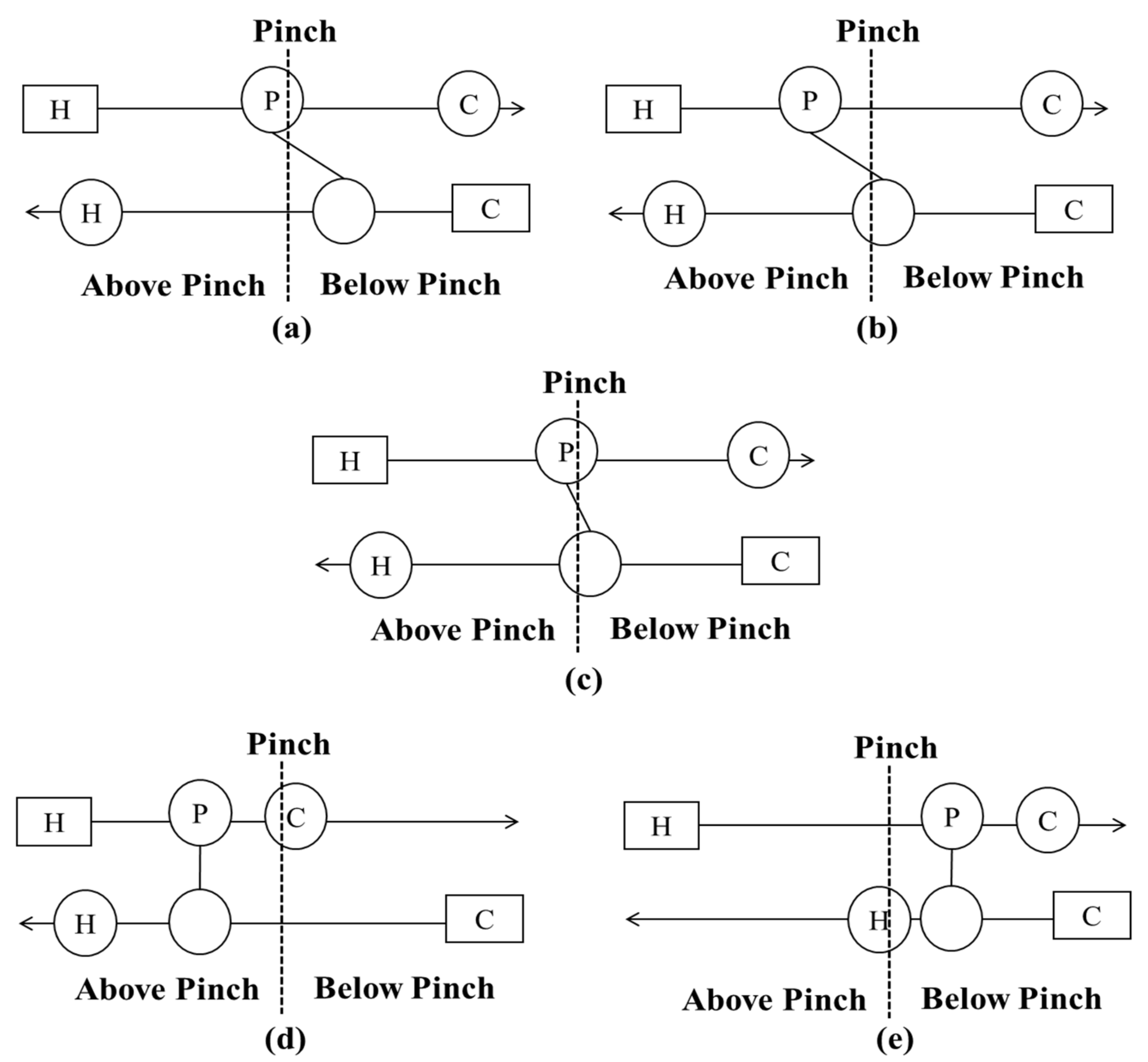
Scenario 1: No pinched exchangers in the network
In this situation, adding a new heat exchanger and creating a utility path is beneficial. The reason for this is that the main restriction to energy recovery is the presence of cross-pinch exchangers.
Therefore, by creating a utility path, the cross-pinch heat transfer can be effectively decreased or eliminated, and energy consumption reduced.
Scenario 2: Process heat exchangers located upstream of pinched exchangers
In this situation, resequencing and adding a new heat exchanger are both beneficial. This is because energy recovery is restricted by the downstream pinched exchanger(s). Therefore, heat load can be moved from the process heat exchangers upstream to relieve the constraint on the pinched exchangers allowing for energy recovery.
If moving the entire heat from the upstream heat exchangers does not violate the temperature driving force, resequencing is recommended. When there are more than one upstream process heat exchangers, the one with highest temperature driving force should be selected to relocate. It should be noted that in the event of more than one exchanger having the same temperature driving force, the one with higher heat duty is preferred.
Adding a new heat exchanger is the most beneficial choice only when moving all load from the upstream heat exchanger across the pinch violates the minimum temperature approach constraints. This way, a new heat exchanger can be added downstream, allowing for some of the heat load to be moved, thereby reducing energy consumption.
Scenario 3: No process heat exchangers located upstream of pinched exchangers
In this scenario, adding a new heat exchanger and stream splitting are considered as the best modifications.
Only when there are more than two pinched heat exchangers adjacent to each other, is introducing stream splitting beneficial. This is because the lower temperature of cold stream and the higher temperature of hot stream ease the driving force constraint of pinched heat exchangers.
Otherwise, adding a new heat exchanger is recommended.
4.2. Multiple Modifications
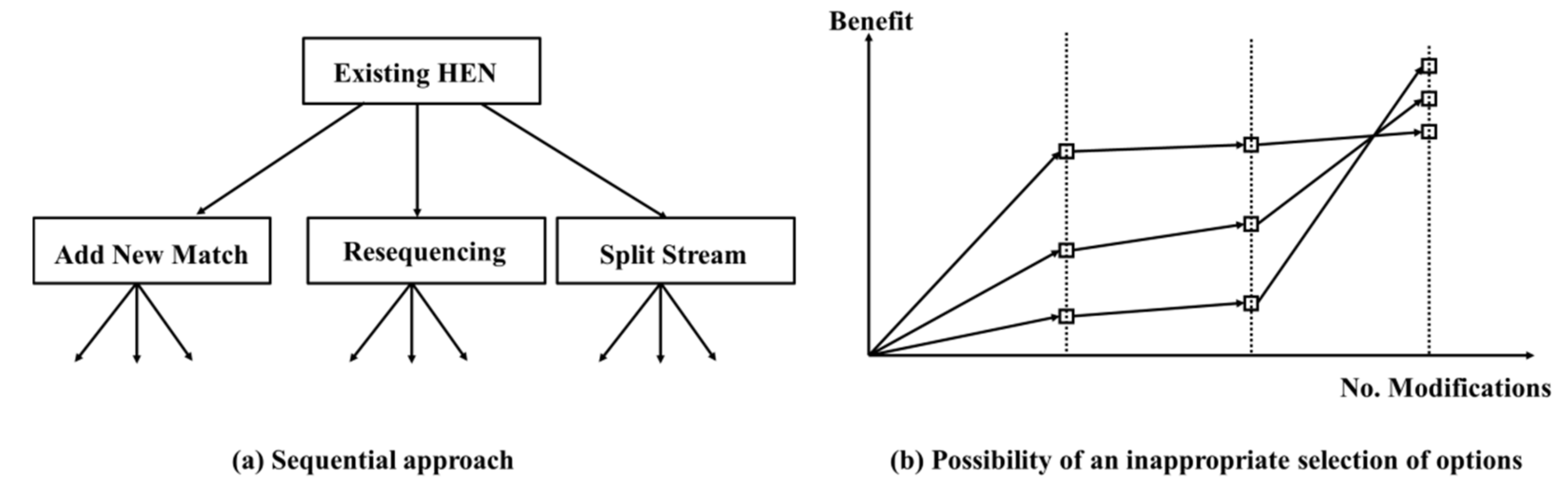
Once the best single modification is identified, further modifications steps need to be obtained, as shown in
Figure 5a. In
Figure 5b, however, it is observed that the sequential repetition of the best single modification does not guarantee an optimal result. As such, the best retrofit strategy is the one that can identify the best series of modifications that ensures the retrofit target, with minimum modification steps and minimum capital cost.
In this work, the step-by-step algorithm shown in
Figure 6 is proposed. The retrofit methodology is repeated, and the network data is updated until the retrofit energy target is met. The best modification at each stage is obtained based on the updated network data and the key features of the new network. Note that the stopping criteria can be different based on the user requirements. The stopping criterion used in this study is the maximum energy recovery.
4.3. Integration of Plate Heat Exchanger into HEN Retrofit
Plate heat exchangers, as one of most efficient types of heat transfer equipment, allow for lower minimum approach temperature (say 5 °C) compared with conventional heat exchangers. Lower approach temperatures make it possible to achieve greater heat recovery and energy saving. The main challenge when integrating PHEs is the handling of different minimum approach temperatures within the same HEN. This work presents a methodology to deal with such challenge. The strategy consists of maintaining the existing Δ
Tmin in the network as a global minimum approach temperature, only for shell-and-tube heat exchangers, whereas a local minimum approach temperature of 5 °C is set for all the new plate heat exchangers. There are three constraints in the optimization process of HENs, as shown in Equations (8)–(10). The first constraint is that the target temperature should be met. The second constraint is that the global minimum approach temperature should be kept as the existing minimum approach temperature in the network. The third constraint is that the local minimum approach temperature for all the new plate heat exchangers should be no smaller than 5 °C. The parameters in this optimization problem are fluid properties for both hot streams and cold streams, which are assumed to be constant in this work.
When integrating plate heat exchangers into existing HENs, the capital cost of PHEs needs to be taken into account, as part of the total retrofit cost. The capital cost of a PHE mainly depends on its area. As such, to obtain the minimum economic installation cost of PHE, the area of PHE needs to be minimized. The heat transfer area for a plate heat exchanger is determined as in Equation (11):
where
Q is the total heat load,
U is the overall heat transfer coefficient,
A is the heat transfer area of the PHE,
and
are the inlet and outlet temperatures of the hot stream, and
and
are the inlet and outlet temperatures of cold streams. Only the overall heat transfer coefficient (
U) is not defined and is possible to be further optimized. The heat transfer coefficient of chevron plate PHEs is dependent on the plate type, flow arrangement, and chevron angle. Among all the variables, the integer variables include the total number of plates in each block, the number of passes for the cold and hot side, plate geometries and chevron angle. There are two constraints. One constraint is that the total heat load transfer should be not less than the required heat load transfer since the area of the plate is an integer. That pressure drop should be maintained in the allowable range is the other constraint. Thus, to minimize the overall heat transfer coefficient, the optimization model can be set up as below in Equation (12).
where
is the number of passes for the hot stream,
is the number of passes for the cold stream,
is the chevron angle, n is the number of plates in each block,
Ptype is the type of plate,
is process heat duty. A mixed-integer non-linear programming (MINLP) model is set up in GAMs with ANTIGONE solver as detailed by Xu et al. [
27]. ANTIGONE is one of the most widely used global solvers for the MINLP optimization problem [
28].
Under some circumstances, even when using plate heat exchangers, the approach temperature of that heat exchanger could be much greater than the minimum allowed owing to the restrictions created by the network structure.
With the use of PHE, the objective of the optimization model is to achieve the maximum heat recovery at the existing minimum approach temperature, with minimum modification steps and capital costs. The stopping criterion is to meet the minimum energy consumption at the specified minimum approach temperature. The reason for the selection of this value over the addition of extra area into the network is to limit the modifications to those that are sufficient to achieve the minimum approach temperature, which in turn provides the maximum heat recovery. To ensure no extra heat recovery is reached, a constraint for heat recovery is required. Equation (13) shows the boundary of hot and cold utility, where
is the hot utility consumption,
is the minimum hot utility consumption at the minimum approach temperature,
is the cold utility consumption and
is the minimum cold utility consumption at the minimum approach temperature.
4.4. Comparison for Different Retrofit Technologies
To quantify the potential benefits of integrating PHEs into the retrofit design of HENs, the retrofit results are compared with those of a network with the same heat recovery, but only using STHXs. The utility cost and retrofit cost data for these two scenarios are shown in
Table 1. The total retrofit cost, utility cost and payback are calculated as shown in Equations (14)–(16).
where
TRC represents the total retrofit cost,
BP is the cost of implementing by-pass,
AA is the cost of adding area,
UC is the total cost of utility saving,
HU is the total cost of hot utility saving,
CU is the total cost of cold utility saving, ε is the payback of the retrofit strategy.
6. Conclusions
A novel step-by-step methodology for the HEN retrofit, which deals with the possibility of designing retrofit strategies considering different minimum approach temperatures for the same HEN via the decoupling of local and global approach temperatures, is proposed. A multi-step retrofit methodology towards the maximum heat recovery at the existing minimum approach temperature is developed on top, to ensure the final solution satisfies all design and operational requirements (e.g., minimum installation cost, maximum heat recovery and minimum number of modifications).
The potential benefits of the proposed methodology are evaluated in three difference case studies. The results in all cases show demonstrate, in order to achieve the same amount of energy recovery, the utilization of plate heat exchangers can significantly reduce the total retrofit cost compared to conventional retrofit strategies, which only consider the use of STHXs. The advantages of PHTs in this context come from the lower minimum approach temperature these units present, which allows for higher heat recovery. The amount of energy saving was only limited by the design of the network (maximum heat recovery). However, the use of PHEs was demonstrated to always be beneficial, due to its low capital cost. Finally, based on the results of the third case study, which is more complex than the previous two, it was demonstrated that the payback time of the proposed methodology is 41% of that for the traditional retrofit method. In addition, the proposed method can be applied on a variety of HEN structures, offering flexibility for a variety of industrial processes.


