Article

Design of a Laboratory Test Equipment for Measuring and Testing Mobile Energy Means with Simulation of Operating Conditions

1
Institute of Agricultural Engineering, Transport and Bioenergetics, Faculty of Engineering, SUA in Nitra, 94976 Nitra, Slovakia
2
Department of Machinery, Faculty of Mechanical Engineering, Politechnika Bydgoska, 85795 Bydgoszcz, Poland
3
Department of Agricultural Engineering, Faculty of Agriculture, University of Novi Sad, 21102 Novi Sad, Serbia
*
Author to whom correspondence should be addressed.
Processes 2022, 10(8), 1435; https://doi.org/10.3390/pr10081435
Submission received: 28 June 2022 / Revised: 19 July 2022 / Accepted: 21 July 2022 / Published: 22 July 2022
(This article belongs to the Section Advanced Digital and Other Processes)

Abstract

:
The presented article deals with the design of equipment for measuring and testing hydrostatic transducers. The presented design of the device is used for measuring and testing hydrostatic transducers in laboratory conditions, especially hydraulic pumps. This shortens the testing time, with a reduction in economic costs for testing the elements of the hydraulic circuit or testing the properties of pumps and hydraulic fluids. By simulating the operating conditions occurring in practice, it is possible to verify and evaluate the parameters of mobile energy means used in hydraulic mechanisms. The designed laboratory equipment is used for measuring and testing hydrostatic transducers and properties of hydraulic fluids. A verification measurement of the flow of the hydrostatic transducer was performed on the proposed laboratory equipment. The output of the measurements is a confirmation of the functionality of the designed equipment. The results of the verification measurement were compared with the data obtained during the simulations in the computer program FluidSIM 5. The output of the measurements is a confirmation of the functionality of the designed equipment. When comparing the results of the verification measurement of the flow on the laboratory equipment with the data given by the manufacturer of the transducer, we recorded a decrease in flow of 5.1% at a speed of 250 rpm in comparison. At 500 rpm we recorded an increase in flow of 2.38% and at 750 rpm there was an increase of 4.15% compared to the data from the manufacturer. The results of the verification measurements were also compared with the simulation in the computer program FluidSIM 5. The flow data obtained by the simulation showed higher values than in the verification measurement. Specifically, at 250 rpm it was an increase of 3.21%, at 500 rpm by 0.39%, and at 750 rpm by 3.14%.

1. Introduction

The use of hydraulic equipment is increasing across all industries, which is mainly due to the advantages and large range of their use. In the presented work, a structural design of a measuring device was created, which was used to determine the functionality and diagnose hydrostatic transducers in laboratory conditions. The presented construction design can simulate the operating load in laboratory conditions, which the hydrostatic transducer is exposed to during its operation in practice. During the measurement itself, the hydrostatic transducer is dismantled from the agricultural machine and installed on a laboratory test device for measurement purposes. The device described in the given work allows the measurement of the parameters of hydrostatic transducers, but it can also measure and test hydraulic energy carriers used in hydraulic devices. The proposed device enables simultaneous testing of two hydrostatic transducers or two types of energy carriers under the same or different conditions; most similar devices allow the testing of one type of hydrostatic transducer or one type of hydraulic fluid. Thus, the described device enables simultaneous testing of several types of liquids or transducers Thanks to the device, we can perform repeated tests of transducers and liquids. The device can monitor the parameters of various types of hydraulic fluids (mineral, ecologically degradable hydraulic fluids). In agricultural machinery, hydrostatic transducers are widely used as part of the hydraulic circuit. These transducers have the main function of supplying the hydraulic circuit with hydraulic fluid, as well as generating pressure energy in the hydraulic circuit. It is therefore necessary to maintain the exact mechanical production of the individual elements of the entire hydraulic circuit, by monitoring the accuracy of CNC machine tools [1,2]. Due to these high demands, especially on hydrostatic transducers used in the agricultural industry, there is a need to test them. It is for these reasons that the design of a laboratory equipment was created, which allows for the testing of the parameters of hydrostatic transducers and hydraulic fluids. Operating fluid is also an important part of hydraulic mechanisms. The author [3] claims that, based on the analysis of the operating fluid, we can determine the technical condition of hydraulic elements located in hydraulic systems. At the same time, it is important to monitor the contamination of the working fluid. According to author [4], the physicochemical properties of hydraulic fluids are also affected by pollution, which results in degradation processes. Oil contamination is the most common and serious source of machine failure [5]. The article also deals on a simulation of the verification measurement in the simulation program, which was compared with the values obtained during the verification measurement at the laboratory equipment.

2. Materials and Methods

According to the author [6], machines which are used in agriculture and forestry are characterized by demanding operational hours and often working in dusty and humid environments. This has negative consequences on the proper functioning of hydraulic systems. Agricultural engineering requires continuous improvement of the service life and reliability of machinery [7]. Laboratory testing devices allow for the simulation of the variable testing conditions of the real conditions under which the hydraulic systems of agricultural wheel tractor operate [8]. The proposed device consists of two hydraulic circuits. One circuit of the measuring chain is primary while the other circuit is secondary, due to the possibility of continuously testing two hydrostatic transducers or two types of hydraulic fluids concurrently under the same or different conditions. Using verification measurements and their results, we demonstrate the suitability of the proposed laboratory test equipment for measuring the parameters of hydrostatic transducers. The importance of monitoring the operating parameters of hydraulic pumps is also confirmed by the authors [9,10], who consider the values of flow and flow efficiency as important indicators of the assessment of hydraulic transducers. Flow and flow efficiency values are used to create dynamic flow models in hydrostatic transducers, using numerical simulation to replicate the environment [11]. We perform flow measurements, from which we determine three critical values, which are compared and evaluated. Subsequently, we simulate in the program FluidSim 5 identical conditions as used when measuring on a laboratory equipment. We compare the values obtained during the measurements. The mathematical relations necessary for the dimensioning of individual elements of the proposed laboratory equipment are as follows:
Hydrostatic transducer flow:
Q = V g · n 1000 · η p r ,   dm 3 · rpm
Power of hydrostatic transducer:
P = V g · n · p 60 · 1000 · η c , W
Inner diameter of the pipe:
d = 4 · Q π · w ,   mm
Torque:
M k = V g ·   P 2 π n ,   N m
Rotation speed of hydraulic motor:
n 1 = Q h m 1 · 1000 · η P V g 1 ,   rpm
n 2 = Q h m 2 · 1000 · η P V g 2 , rpm
Tank volume:
V = Q i ,   dm 3
Pipe volume:
V p = 2 π · r · h ,   dm 3
Cooler performance:
P v = Δ T · C ·   ϱ · V t · 60 ,   W
where: V g volume of hydrostatic transducer, dm3; n speed of rotation hydrostatic transducer, rpm; η p r flow efficiency of the hydrostatic transducer; p pressure, MPa; η c overall effectiveness; w velocity of flow, m·s−1, Q h m 1 , Q h m 2 flow of hydraulic motor, dm3·rpm; i circulation number of the tank, min; r radius, m; h height, m; Δ T temperatur difference, °C; t time, s; ϱ denstiy, km·m3; C specific heat capacit of hydraulic oil, J kg · K [12].
Prior to the actual measurements on the designed laboratory equipment, it is necessary to heat the working fluid in the measuring chain to a temperature of 50 °C based on the SAE J745 standard (Hydraulic Power Pump Test Procedure). The SAE J745 standard deals with test procedures for hydrostatic transducers. PARAMO HM 46 oil is used as the hydraulic charge when measuring the flow of the hydrostatic transducer at the designed laboratory equipment, its parameters are in Table 1. According to authors [13,14], the results of measurements affect the physicochemical properties, pollution, and temperature of the working fluid.
We monitor gear hydrostatic transducer UD-25R, the technical parameters of which are given in Table 2.
Part of hydraulic circuits are the associated sensors, through which we can measure pressure, temperature, and flow. In the proposed laboratory equipment, an associated EVS 3 100 sensor is used to measure physical quantities. Authors [15,16] state in their work that the operating parameters, especially temperature and pressure, have an impact on the measurements as well as the thermophysical properties of the used fluid. We use the HYDAC HMG 3010 unit to record and display quantities from sensors, the maximum inaccuracy of which is ± 1%. The technical data of the mentioned sensor are given in Table 3. Table 4, Table 5, Table 6, Table 7, Table 8, Table 9, Table 10 and Table 11 show the technical parameters of individual elements of the proposed laboratory equipment.

Design of Laboratory Test Equipment

Figure 1 shows the scheme of the designed laboratory equipment. The author [17] dealt with the measurement of the characteristics of hydraulic elements in laboratory conditions.
The equipment consists of two circuits (labeled A and B) due to parallel the simultaneous testing of two hydrostatic transducers or two energy carriers under the same or different operating conditions. The primary circuit is located next to a three-phase asynchronous electric motor EM. In front of the electric motor there is a frequency converter, which is used to set the speed on the electric motor EM. The electric motor supplies mechanical energy to the hydrostatic transducer HP1. Furthermore, there is a pressure valve PV1 in the primary circuit, which performs a safety function. When the set pressure is exceeded, the pressure valve releases the fluid back into the tank, thus protecting the hydraulic circuit from a dangerous condition. The pressure valve is also located in the PV2 secondary circuit. In both circuits of the designed device there are also filters F1 and F2. According to [18], filters and filtration systems affect the operation and technical condition of the machines and equipment of which they are a part. T1 and T2 serve as reservoirs of hydraulic fluid located in both hydraulic circuits. With two tanks, two types of hydraulic fluids may be tested simultaneously under the same or different conditions. In the primary circuit there is a hydraulic motor HM, which is used to convert pressure to mechanical energy. The HM hydraulic motor is connected to the HP2 hydrostatic transducer through a mechanical coupling. HP2 is a hydrostatic transducer UD-25R. We will monitor the change in flow depending on the rotation speed on the mentioned transducer. In the secondary hydraulic circuit, there is a three-way valve TV. The three-way valve has two positions: in the first position the liquid flows into the reducing valve RV, while in the second position the liquid flows through the proportional valve PV. The reducing valve is used to load the elements of the hydraulic circuit and to heat the working fluid. When measuring with the designed device, it is possible to derive a load (pressure) by means of a proportional PV valve, which we use to simulate operating conditions. The proportional valve is located in the secondary circuit. By loading the secondary circuit, we also load the primary circuit, as the given hydraulic circuits are mechanically connected. The proportional valve can be connected to a computer and a set of pressures can be obtained from the operating conditions loaded into it and used to create the required load. Another part of the proposed laboratory equipment is the Hydac HMG 3010 recording unit, which are connected to sensors (Q, p, t).
In Figure 2, laboratory test equipment for testing mobile energy means and working fluids is displayed.
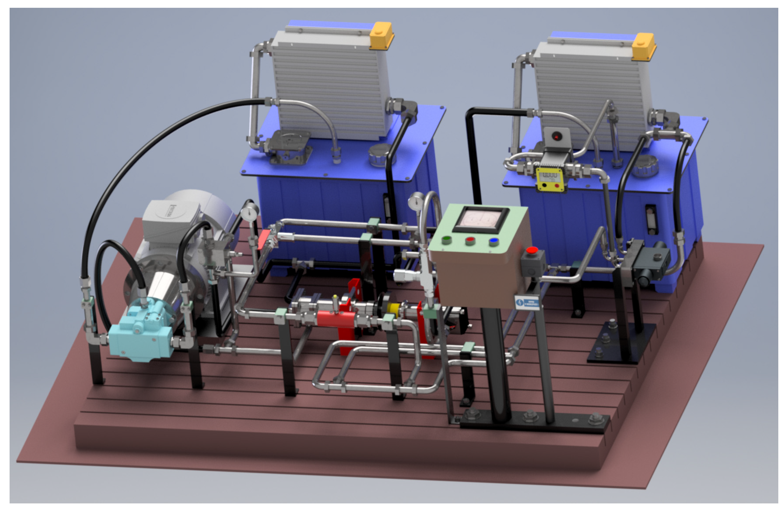
Figure 3 shows a laboratory test equipment for testing mobile energy means and working fluids, drawn in a 3D program.
Table 12 shows the basic dimensions of the laboratory equipment.

3. Results

3.1. Measurement of Hydrostatic Transducer Flow on the Designed Laboratory Test Equipment

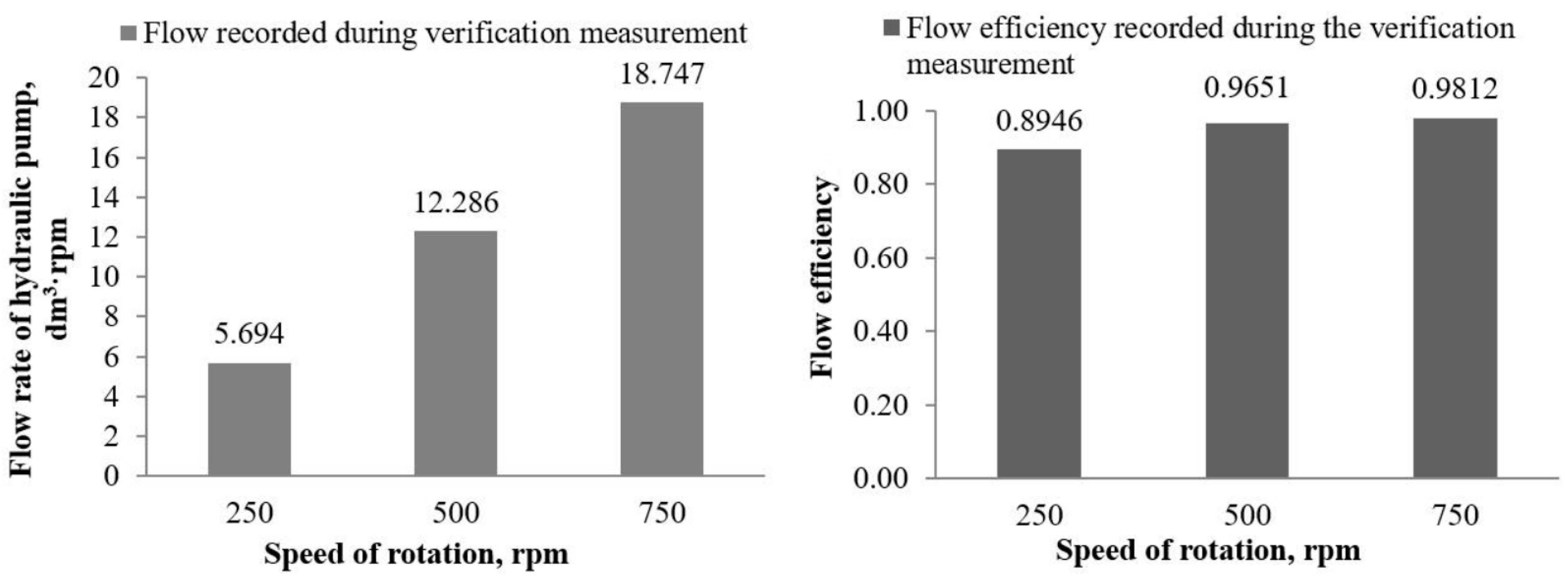
During the verification measurement, we monitored the flow of the hydrostatic transducer UD-25 R. Measurement procedure for measuring the flow of hydrostatic transducer UD-25R is as follows. We set the required rotation speed on the electric motor through the frequency converter. We heated the working fluid to working temperature, which is 50 °C. When measuring the hydraulic pump flow, we set the following rotation speed values: 250, 500 and 750 rpm. At each of the set rotation speeds, the HYDAC HMG 3010 recorded the measured values from the sensors. During measurement, it was necessary to ensure a stable temperature value at 50 °C. The author [17] also stated in her work that it is important to monitor the temperature of the working fluid, due to its influence on the resulting values of measurements. We processed and evaluated the obtained data.
In Figure 4, it is possible to see the flow rate and hydrostatic transducer values recorded during measurements on the designed laboratory equipment.
Table 13 shows the files of descriptive statistics of the values recorded during the verification measurement.
It is the oil flow that is important for the life of the hydraulic system [19].

3.2. Hydrostatic Transducer Flow Measurement—Simulation

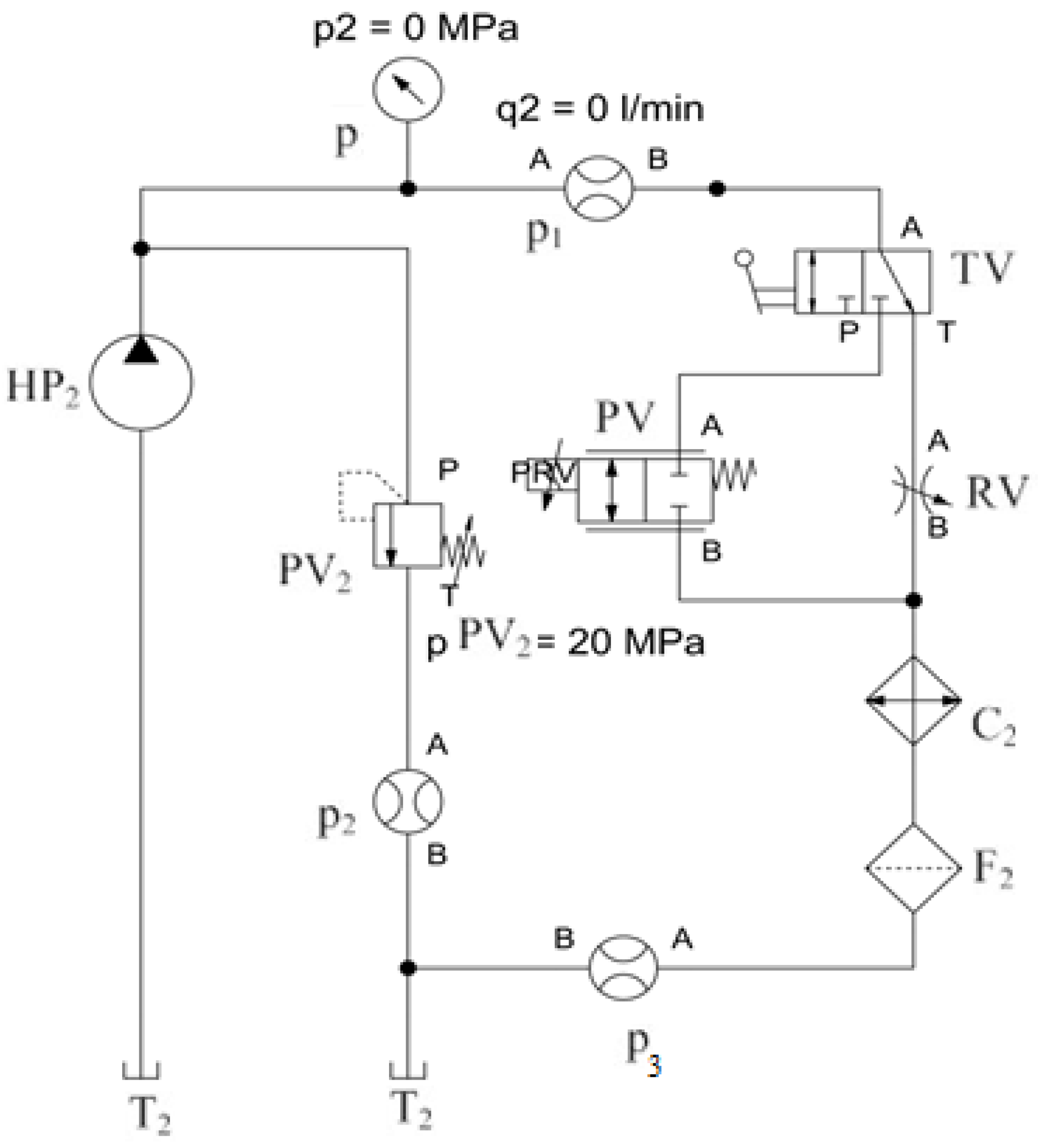
The flow measurement of the UD-25R hydrostatic transducer was performed in the FluidSIM5 computer simulation program. During the simulations, we tried to approach the conditions and technical parameters of individual hydraulic elements, which contain the proposed laboratory equipment.
Figure 5 shows the circuit diagram of the secondary circuit of the laboratory equipment drawn in the FludSim5 program, on which the simulation is performed and then the results obtained are compared with the data measured on the laboratory test equipment.
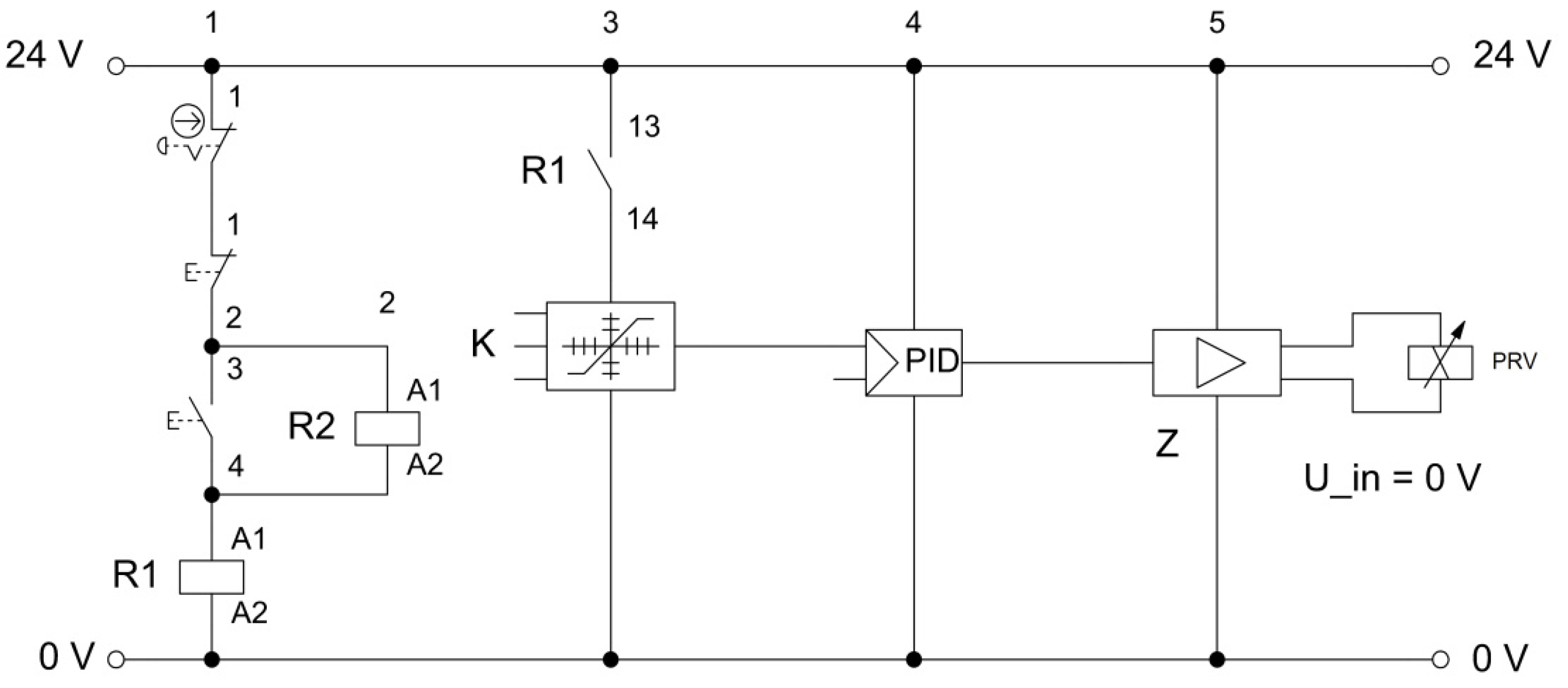
In Figure 6, it is possible to see the electrical circuit used to control the proportional valve, which serves to load the hydraulic circuit and its element.
The values recorded during the simulation (Table 14) showed higher flow as a value recorded during the verification measurement, where the increase of the flow value was by 3.21% at the converter speed n1 = 250 rpm, by 0.39% at the speed n2 = 500 rpm and by 3.14% at the speed n3 = 750 rpm. Differences between the values recorded during the simulation and during the measurements on the designed equipment could be caused by several factors. For example, in the simulations of a given FludSIM5 program, it is not possible to fully simulate the conditions as in the flow measurements of a given hydrostatic transducer. It is possible that during the verification measurement on the laboratory test equipment there were minor leaks or seepages, which are not in the program during the simulations. Another reason for the difference may be the hydraulic fluid itself. During the simulations in the computer program FluidSIM5, only the data on the viscosity of the working fluid specified by the manufacturer at a certain temperature could be set. This viscosity did not change during the simulation when measured by laboratory test equipment, however the viscosity of the working fluid may have changed during the measurement based on the temperature, which would have had a significant effect on the physico-chemical properties of the fluid.

4. Discussion

The proposed laboratory equipment in the article will be used to measure and test mobile energy means with simulation of operating conditions. The proposed device enables simultaneous testing of two hydrostatic converters or two types of energy carriers under the same or different conditions. We declared the suitability of the design by verification measurements on the proposed equipment. Laboratory equipment allows repeatability of measurements in laboratory conditions by simulating operating conditions. Author [20] focused on the design of laboratory equipment for measuring the parameters of mobile energy means. In his work, he stated that there is an increased interest in testing methods in laboratory conditions. Based on the designed laboratory test equipment, it is possible to shorten the testing time of hydrostatic transducers, hydraulic fluids, and hydraulic elements. Thanks to the results obtained in the measurement of the hydrostatic transducer, it is possible to make changes in the design of the subject equipment before their introduction into the production process. It is also possible to test environmentally degradable fluids in the proposed equipment, which according to the author [21] must meet the requirements for the operation of hydraulic equipment in terms of low impact on the wear of hydraulic components. Author [22] states in their work that testing under laboratory conditions is appropriate mainly for reasons of the repeatability of tests and also because of a shortening of testing time.

5. Conclusions

The need to test energy carriers and transducers used in hydraulic mechanisms is increasing due to environmental requirements. The analysis of hydraulic fluids in operating conditions, and its influence on the operating parameters of individual elements of the hydraulic system, has already been dealt with in the work of the authors [23,24]. At the same time, it is important to perform a comprehensive analysis of the effect of fluids and their mixtures, which was dealt with by the author [25] in his work. The results of the presented work result in the following benefits:
  • on the basis of the designed laboratory test equipment, it is possible to shorten the time of operational tests of hydrostatic transducers, hydraulic fluids and hydraulic elements;
  • using the designed laboratory test equipment, we are able to design various types of measuring chains, the task of which will be testing elements of hydraulic circuits or hydraulic fluids;
  • using the designed laboratory test equipment, we can perform repeated tests in laboratory conditions with the same or different operating loads;
  • it is possible to simultaneously test the parameters of two hydrostatic transducers in the laboratory test equipment;
  • on the basis of the acquired knowledge and results of measurements of the hydrostatic transducer, it is possible to make changes in the structures of the devices in question even before they are introduced into the production process.
Based on the above, it can be concluded that the designed laboratory test equipment can be used in social practice, and the equipment is also beneficial for the further development of applied science. Owing to laboratory testing equipment, it is possible to significantly shorten the testing of parameters of hydrostatic transducers, as well as to shorten the testing of the properties of individual types of energy carriers used in hydraulic circuits. The results of articles are used to improve knowledge and experience in the field of testing and testing the parameters of hydrostatic transducers and energy carriers. In the designed device, it is also possible to test ecologically degradable liquids, which nowadays are given more emphasis. The economic benefit is the acceleration of tests of hydrostatic transducers and hydraulic fluids, which significantly shortens the time of testing and which has a positive impact on economic indicators. Thanks to its modularity, the designed laboratory equipment also enables the testing of other types of hydrostatic transducers used in hydraulic mechanisms. In the presented article, a verification measurement and simulation of hydrostatic transducer flow measurements with data comparison is performed. When measuring the flow rate of the hydrostatic transducer, minimal deviations from the data obtained on the proposed device and the data obtained during the simulation in the program were noted.

Author Contributions

Conceptualization, Ľ.H. and J.N.; methodology, S.B.; software, Ľ.H. and J.N.; validation, S.B. and M.T.; formal analysis, M.M.-P. and P.K.; resources, Ľ.H. and J.N.; writing—original draft preparation, M.T. and P.K.; writing—review and editing, J.N. and P.K.; supervision, Ľ.H. and M.M.-P.; project administration, Ľ.H.; funding acquisition, Ľ.H. and J.N. All authors have read and agreed to the published version of the manuscript.

Funding

Slovak University of Agriculture in Nitra.

Institutional Review Board Statement

Not applicable.

Informed Consent Statement

Not applicable.

Data Availability Statement

The possible sources pointing to the results in the form of a link below: https://journals.sagepub.com/doi/full/10.1177/0020294020983385.

Acknowledgments

This publication was supported by the Operational Program Integrated Infrastructure within the project: Demand-driven research for the sustainable and innovative food, Drive4SIFood 313011V336, cofinanced by the European Regional Development Fund.

Conflicts of Interest

The authors declare no conflict of interest.

References

  1. Košinár, M.; Kuric, I. Monitoring of CNC machine tool accuracy. New Product Development in Business to Business Marketing a Relational Perspective. In Proceedings of the 1st International Conference on Quality and Innovation in Engineering and Management, Cluj-Napoca, Romania, 17–19 March 2011; pp. 115–118. [Google Scholar]
  2. Kuric, I.; Zajačko, I.; Císar, M. Analytical Intelligence tools for multicriterial of CNC machines. Adv. Sci. Technol. Res. J. 2016, 10, 59–64. [Google Scholar] [CrossRef] [Green Version]
  3. Kučera, M.; Aleš, Z.; Pexa, M. Detection and Characterization of Wear Particles of Universal Tractor Oil Using of Particles Size Analyser. Agron. Res. 2016, 14, 1351–1360. [Google Scholar]
  4. Zastempowski, M. Test Stands with Energy Recovery System for Machines and Hydraulic Transmission. J. Res. Appl. Agric. Agric. Eng. 2013, 58, 188–191. [Google Scholar]
  5. Kučera, M.; Majdan, R.; Abrahám, R.; Kučera, M.; Hass, P. Analysis of the effect of loading process on tribological system properties. Acta Univ. Agric. Silvic. Mendel. Brun. 2016, 64, 825–833. [Google Scholar]
  6. Simikič, M.; Dedovič, N.; Savin, L.; Tomič, M.; Ponjičan, O. Power delivery efficiency of a wheeled tractor at oblique drawbar force. Soil Tillage Res. 2014, 141, 32–43. [Google Scholar] [CrossRef]
  7. Tóth, F.; Fürstenzeller, A.; Rusnák, J.; Bošanský, M.; Kadnár, M. The possibilities of using ecological liquids in tribological gliding systems with a selected surface created by the radial welding technology. Acta Technol. Agric. 2019, 22, 134–139. [Google Scholar] [CrossRef] [Green Version]
  8. Hujo, Ľ.; Čorňák, Š.; Tkáč, Z.; Jánošová, M. Laboratory Research of Transmission-Hydraulic Fluid, Praha. In Proceedings of the 7th International Conference on Trends in Agricultural Engineering, Prague, Czech Republic, 17–19 September 2019; pp. 17–20. [Google Scholar]
  9. Majdan, R.; Tkáč, Z.; Abrahám, R.; Szabó, M.; Halenár, M.; Rášo, M. Proposal for filtration system for biodegradable lubricants in agricultural tractors. Agron. Res. 2016, 14, 1395–1405. [Google Scholar]
  10. Majdan, R.; Tkáč, Z.; Abrahám, R.; Kollárová, K.; Vitázek, I.; Halenár, M. Filtration systems design for universal oils in agricultural tractors. Tribol. Ind. 2017, 39, 547–558. [Google Scholar] [CrossRef] [Green Version]
  11. Puškár, M.; Brestovič, T.; Jasminská, N. Numerical simulation and experimental analysis of acoustic wave influences on brake mean effective pressure in thrust-ejector inlet pipe of combustion engine. Int. J. Veh. Des. 2015, 67, 63–67. [Google Scholar] [CrossRef]
  12. Hujo, Ľ.; Jablonický, J.; Tkáč, Z. Návrh Inovatívneho Laboratórneho Simulačného Zariadenia na Skúšanie Hydrostatických Prevodníkov a Hydraulických Kvapalín, 1st ed.; SUA: Nitra, Slovakia, 2017; 140p.
  13. Halenár, M.; Kuchar, P. Research of biodegradable fluid during operating test. MendelNet 2017. In Proceedings of the 24th International PhD Students Conference, Brno, Czech Republic, 8–9 November 2017; pp. 784–788. [Google Scholar]
  14. Kumbár, V.; Dostál, P. Oils degradation in agricultural machinery. Acta Univ. Agric. Silvic. Mendel. Brun. 2013, 61, 1297–1303. [Google Scholar] [CrossRef] [Green Version]
  15. Kopiláková, B.; Turza, J.; Hujo, Ľ.; Kosiba, J. Evaluation of Hydraulic Resistance in Various Liquids and Temperature. Tribol. Ind. 2017, 39, 129–135. [Google Scholar] [CrossRef] [Green Version]
  16. Csillag, J.; Petrovič, A.; Vozárová, V.; Bilčík, M.; Božiková, M.; Holota, T. Comparasion of rheological properties of new and used biolubricants. In Proceedings of the 7th International Conference on Trends in Agricultural Engineering, Prague, Czech Republic, 17–19 September 2019; pp. 103–108. [Google Scholar]
  17. Kopiláková, B.; Zápotočný, J.; Eckert, M. Methodology for measuring and assessing static characteristics of liquid elements. Univ. Rev. 2019, 13, 8–15. [Google Scholar]
  18. Kaszkowiak, J.; Borowski, S.; Kaszkowiak, E.; Dulcet, E.; Zastempowski, M.; Hujo, Ľ. Systemy filtrowania spowietrza w ukladach zasilania silników spalinowych maszyn roboczych. Logistyka 2015, 4, 1893–1898. [Google Scholar]
  19. Kosiba, J.; Čorňák, Š.; Glos, J.; Jablonický, J.; Vozárová, V.; Petrovič, A.; Csillag, J. Monitoring Oil Degradation During Operating Tests. Agron. Res. 2016, 14, 1626–1634. [Google Scholar]
  20. Tkáč, Z.; Drabant, Š.; Majdan, R.; Cvíčela, P. Testing stands for laboratory tests of hydrostatic pump of agricultural machinery. Res. Agric. Eng. 2008, 54, 127–141. [Google Scholar] [CrossRef] [Green Version]
  21. Tkáč, Z.; Čorňák, Š.; Cviklovič, V.; Kosiba, J.; Glos, J.; Jablonický, J.; Bernát, R. Research of biodegradable fluid impacts on operation of tractor hydraulic system. Acta Technol. Agric. 2017, 20, 42–45. [Google Scholar] [CrossRef] [Green Version]
  22. Hujo, Ľ.; Nosian, J.; Zastempowski, M.; Kosiba, J.; Kaszkowiak, J.; Michalides, M. Laboratory Test of the Hydraulic Pump Operating Load with Monitoring of Changes in the Physical Properties. Meas. Control 2021, 54, 243–251. [Google Scholar] [CrossRef]
  23. Čorňák, Š. Identification of Operating Fluids with Fingerprint Method Utilization. In Proceedings of the 17th International Scientific Conference Engineering for Rural Development, Jelgava, Latvia, 23–25 May 2018; pp. 2048–2053. [Google Scholar]
  24. Kučera, M.; Aleš, Z.; Ivandič, Z.; Hujo, Ľ. Possibility of Hydraulic Fluids with a Low Environmental Impact Application in Agricultural and Transport Machinery. J. Cent. Eur. Agric. 2013, 14, 1592–1601. [Google Scholar] [CrossRef]
  25. Puškár, M.; Jahnátek, A.; Kuric, I.; Kádárová, J.; Kopas, M.; Šoltésová, M. Complex analysis focused on influence of biodiesel and its mixture on regulated and unregulated emissions of motor vehicles with the aim to protect air quality and environment. Air Qual. Atmos. Health 2019, 12, 855–864. [Google Scholar] [CrossRef]
Figure 1. Laboratory equipment for measuring the parameters of hydrostatic transducers. Legend: (A)—primary hydraulic circuit (left side on figure); (B)—secondary hydraulic circuit (right side of figure); EM—electromotor; HP1—regulatory hydrostatic transducer; PV1, PV2—pressure valve; HM—regulatory hydraulic motor; HP2—tested hydrostatic transducer; C1, C2—cooler; t—temperature sensor for tanks; T1, T2—tanks; F1, F2—filters; p—pressure gauge; RV—reducing valve; TV—three-way valve; PV—proportional reducing valve; MC—mechanical coupling, n—rpm sensor, t1, t2—temperature sensors, Q1, Q2—flow rate sensors, p1, p2—pressure sensors, HMG 3010—recording unit.
Processes 10 01435 g001
Figure 2. Laboratory equipment for measuring the parameters of hydrostatic transducers.
Processes 10 01435 g002
Figure 3. Test equipment for measuring the parameters of hydrostatic transducers.
Processes 10 01435 g003
Figure 4. Hydrostatic transducer flow and flow efficiency values recorded during the measurements.
Processes 10 01435 g004
Figure 5. Scheme of the secondary hydraulic circuit of laboratory test equipment. Legend: HP2—hydrostatic transducer UD-25R; p—pressure gauge; p1, p2, p3—flow rate sensors; PV2—pressure valve; F2—filter; C2—cooler; RV—reducing valve; TV—three-way valve; PV—proportional reducing valve.
Processes 10 01435 g005
Figure 6. Electric circuit for controlling the electro-hydraulic proportional valve.
Processes 10 01435 g006
Table 1. Basic characteristics of PARAMO HM 46 oil.
ParameterUnitPARAMO HM 46
Point of fluidity°C−27
Flash point°COver 190
InflammabilityIV. hazard class
Vapor pressure at 20 °CPa<10
Relative density at 15 °C kg · m 3 865
Solubility-Insoluble in water
Auto-ignition temperature °COver 320
Kinematic viscosity at 40 °C mm 2 · s 1 41.4–50.6
Explosive propertiesIt is not explosive
Oxidizing propertiesIt is not oxidizing
Table 2. Technical parameters of hydrostatic transducer UD–25 R.
ParameterUnitValue
Rated rotation rpm 1500
Maximum rotation3200
Minimum rotation450
Maximal pressure at the inlet MPa 0.05
Minimum inlet pressure0.03
Nominal outlet pressure MPa 20
Maximum outlet pressure23
Geometric volume dm 3 0.02546
Maximum oil viscosity mm 2 · s 1 1200
Minimum oil viscosity10
Maximum oil temperature°C80
Minimum oil temperature−20
Table 3. Technical data of the sensor HYDAC EVS 3 100.
Input Data
Measuring range, dm3·min−1Operating pressure, MPa
1.2–2040
6.0–6040
15.0–30040
40.0–60031.5
Input Data
Output signal, allowed load resistance4–20 mA, RLmax = (UB − 10 V/20 mA, Kω)
Accuracy 2% real value
Additional Data
Compensated temperature range−20 until + 70 + °C
Operating temperature range−20 until + 70 + °C
Fluid temperature range−20 until + 90 + °C
Protection classIP 65
Supply voltage10–32 V
Residual ripple of the supply voltage 5%
Viscosity range1–100 mm2·s−1
Calibration viscosity30 mm2·s−1
Table 4. Technical parameters of an asynchronous electric motor (EM).
ParameterUnitValue
Protection class-IP 55
Rated power kW 11
Rated voltage V Δ   380 420 /   Y   660 720
Rated current A Δ   21.6 / Y   12.5
Nominal speed rpm Δ   1450 / Y   1740
Table 5. Technical parameters of the axial piston hydraulic pump P22-A3-F-R-01 (HP1).
Volume, dm 3 No-Load Flow, dm 3 · rpm Maximum PressureSpeed of Rotation, rpm Weight, kg
0.022 1000   rpm 1200   rpm 1500   rpm 1800   rpm 25.5 MPaMin.Max.
22.026.433.039.6300200013
Table 6. Technical parameters of the pressure valve VMP 3/4 (PV1, PV2).
ParameterUnitValue
Pressure rangeMPa5–25
Weightkg1.470
Flowdm3·rpm90
Maximum pressureMPa35
Table 7. Technical parameters of the Hydromotor AC-K-16-7 (HM).
ParameterUnitValue
Nominal pressureMPa25
Maximum pressureMPa35
Geometric volumedm30.0285
Rated speed of rotationrpm2700
Maximum rotation speedrpm4800
Nominal flow ratedm3·rpm52.8
Maximum flowdm3·rpm128.4
Weightkg12.5
Table 8. Technical parameters of the filter SOFIMA RFM 040 (F1, F2).
ParameterUnitValue
Filtrationµ25
Filter material-cellulose
Maximum flowdm3·rpm110
Maximum working pressureMPa0.3
Burst pressureMPa1
Bypass valve pressureMPa0.15
Filter cartridge symbol-CRE050CV1
Table 9. Technical parameters of the cooler EMMEGI (C1, C2).
ParameterUnitValue
Typ-2024 K 230–400 60–49 ASP
TensionV230/400
PowerkW0.105/0.145
Protection class -IP 44
Thermal protection-no
Rotation speed of fanrpm2500/2650
Maximum oil pressure in the system, operating pressureMPa2
Weightkg11
Table 10. Technical parameters of the throttle valve VRB 90 (RV).
ParameterUnitValue
Maximum flowdm3·rpm80
Weightkg1.080
Maximum pressureMPa28
Table 11. Technical parameters of the proportional valve DKZOR-A (PV).
ParameterUnitValue
Pressure limitsMPaPorts P, A, B = 31.5
T = 21
Maximum flow at Δp = 1 MPadm3·rpmPorts P, A, B = 45
T = 60
Maximum flow at Δp = 3 MPadm3·rpmPorts P, A, B = 80
T = 105
Maximum flow at Δp = 7 MPadm3·rpmPorts P, A, B = 120
T = 160
Response timems<40
Hysteresis % 5%
Repeatability- ± 1%
Ambient temperature°C−20 until + 70
Recommended viscosity at 40 °Cmm2·s−115–100
Oil temperature°C−20 until + 80
Maximum Solenoid Current at 3.8–4.1 ΩA2.6
Maximum Solenoid Current at 2.2–2.4 ΩA3.25
Maximum Solenoid Current at 12–12.5 ΩA1.2
Table 12. Basic dimensions of the proposed device.
Maximum Length (Base), mmMaximum Width (Base), mmMaximum Height, mm
19301130830
Table 13. Results of descriptive statistics from the set of flow values at the specified values of rotation of speed.
ParameterRotation Speed n, rpm
250500750
Arithmetic mean5.69412.28618.747
Standard error0.17650.06130.0055
Median5.7612.318.76
Modus5.8512.318.76
Standard deviation0.10.10.1
Selection variance0.0310.0030.003
Pointiness−1.255−0.023−0.041
Skewness−0.532−0.0080.20
Range0.600.350.34
Minimum5.312.1318.59
Maximum5.912.3918.85
Confidence limit (90.0%)0.0080.0030.002
Table 14. Recorded values of the hydrostatic transducer flow during the simulation.
Rotation Speed, n, rpmArithmetic Mean Flow Rate, Q, dm3·rpmFlow Efficiency η,
2505.8770.9233
50012.3340.9688
75018.8060.9848
Publisher’s Note: MDPI stays neutral with regard to jurisdictional claims in published maps and institutional affiliations.