Abstract
The non-uniform inflow caused by the elbow inlet is one of the main reasons for the low actual operation performance of a centrifugal pump. Orthogonal experiment and GA_PSO algorithm are used to improve the head and efficiency of a centrifugal pump with an elbow inlet based on the method combining numerical simulation and prototype experiment in this paper. The effects of the design parameters, including elbow inlet radius ratio, blade inlet angle, blade number, blade wrap angle, blade outlet angle, impeller outlet diameter, blade outlet width and flow area ratio, on the pump head and efficiency are studied in the orthogonal experiment. The blade inlet angle is the major factor to match the non-uniform inflow and reduce the flow loss in the impeller inlet to contribute to enhancing the pump performance and cavitation characteristics. The particle swarm optimization (PSO) algorithm is optimized by integrating the genetic algorithm (GA), which ensures that the PSO-calculation result avoids falling into the local optimization and the global optimal solution is obtained as quickly as possible. The centrifugal pump with an elbow inlet is optimally designed by the GA_PSO algorithm. According to the performance test results, the efficiency of the optimized pump is 4.7% higher than that of the original pump.
1. Introduction
The elbow inlet is usually mounted in front of the centrifugal pump due to limited installation space or a special inlet environment, which causes the non-uniform inflow at the pump inlet. The non-uniform inflow velocity distribution will not only affect the hydraulic performance and cavitation performance of centrifugal pump, but also excite some large pressure pulsations, causing pump vibration.
Mitsukiyo [1] tested the performance characteristics of the centrifugal pump with an elbow inlet and found that the inlet flow structure of the pump impeller was non-uniform. After the fluid passes through the elbow, because of the action of centrifugal force, the pressure near the outside of elbow inlet increases, while the pressure close to the inside decreases, this phenomenon forms secondary flow structure in the pipe cross section [2,3,4]. The secondary flow caused by the elbow is superimposed with the rotating flow caused by the impeller, which induces some energy losses in the inflow of the pump.
The energy loss caused by the non-uniform inflow includes the hydraulic loss of the elbow inlet and the power loss of the pump impeller. Under the operation condition of the water-jet pump, the energy loss of the elbow inlet is about 7–9% [5,6]. The design of the centrifugal pump is generally based on the uniform inflow. The velocity of each fluid particle in the inlet section of the impeller is approximately the average velocity on the flow surface, while the direction is perpendicular to the outlet section of the suction chamber [7,8,9]. Under this ideal environment, the blade design makes the impeller achieve the best work. However, the inflow velocity distribution is non-uniform, in fact, that is, the velocity of each fluid particle in the inlet section is far from the average velocity and in different ways. In the design of blade inlet edge is difficult to ensure that the circumferential position matches the inflow angle. Most of the inflow works at the large attack angle or negative attack angle, which increases the impact loss to lower the head and pump efficiency. Guo [10] and Mark [11] analyzed the flow rate distribution and velocity distribution in the pump inlet under the elbow inflow condition, and found that the reasonable design of the elbow radius ratio contributed to improving the non-uniformity of the inflow. Meanwhile, the non-uniform inflow causes the increase of the critical cavitation allowance [12,13], and then an obvious asymmetry structure of the cavitation area appeared in the impeller to reduce the cavitation performance of centrifugal pump.
The non-uniform distribution of pump inflow speed and the position of inflow impact, induce an uneven load distribution on the blade [14,15,16]. The unbalanced torque is generated to act on the impeller, and then to form the unstable force, resulting in the pump vibration and noise, which affect the stable operation of the pump unit. Bulten [17] found that the non-uniform inflow has little effect on the stator–rotor interaction between impeller and volute, but the additional radial force is produced by the non-equilibrium torque impacting on the impeller. The greater the non-uniformity of the pump inflow, the higher the magnitude of the radial force, which increases the bearing load to cause the pump vibration.
The non-uniform elbow inflow lowers the performance characteristics of centrifugal pump. In this paper, the effects of main design parameters of the centrifugal pump with an elbow inlet on the pump performance are studied by using the orthogonal experiment. The method of combining a model experiment with computational fluid dynamics (CFD) is applied to obtain the orthogonal experiment results. The GA_PSO algorithm is used to optimally design the pump with an elbow inlet based on the orthogonal results. This work provides some evidence in analyzing the effects of non-uniform elbow inflow on the pump performance.
2. Materials and Methods
2.1. Centrifugal Pump Specifications
The main focus of this research is to understand the key parameters affecting the performance characteristics of centrifugal pumps with 90° elbow inlets and to optimize the pump. The design operating condition and major parameters of model pump are exhibited in Table 1 and Table 2, respectively. The 90° elbow inlet is processed by the organic glass material, while the impeller is rapidly prototyped by the ABS resin material. The pump volute is designed as a conventional single volute spiral type and processed by the cast iron, as shown in Figure 1.

Table 1.
Design requirement of centrifugal pump.
Table 2.
Design parameters of centrifugal pump.
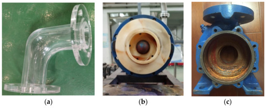
Figure 1.
Centrifugal pump model. (a) elbow inlet. (b) impeller. (c) volute.
2.2. Experimental Measurements
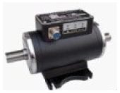
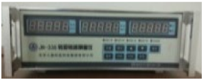
The experiment device and the measuring system are designed for centrifugal pumps with 90° elbow inlets and used for the performance test and cavitation test of a model pump. The suction system is applied to the pump test, which is composed of a model pump, torque speed sensor, pressure sensor, electromagnetic flowmeter, open-type tank, etc. (see Figure 2). The water is sucked out from the open-type tank, and then enters the pump suction pipe through the electric butterfly valve. Pressure sensors are installed on the inlet and outlet pipelines of the model pump, and the pressure measuring positions are respectively arranged at the locations which are twice of the pipe diameter. Four pressure tapping holes are evenly arranged on the circumference of the pressure measuring position, and the pressure is taken by the pressure equalizing water ring. The electromagnetic flowmeter is installed on the pump outlet pipeline, and the length of its upstream and downstream pipelines is greater than 10 times of the pipe diameter, as Figure 3 shows. The accuracy of the experiment device is synthesized by the square root of the measuring instrument accuracy based on Equation (1). According to the accuracies of the instrument and equipment configurations in Table 3, the accuracy of the pump experiment device is e = ±0.63%.
where e is the accuracy of the experiment device, %. ei is the accuracy of each instrument, %.
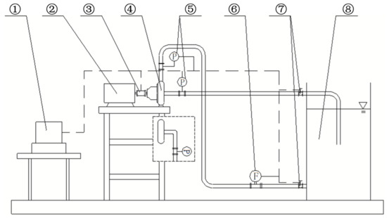
Figure 2.
Schematic diagram of experimental apparatus. ①—Measuring system, ②—Motor, ③—Torque speed sensor, ④—Centrifugal pump model, ⑤—Pressure sensor, ⑥—Electromagnetic flowmeter, ⑦—Electric butterfly valve, ⑧—Open-type tank.
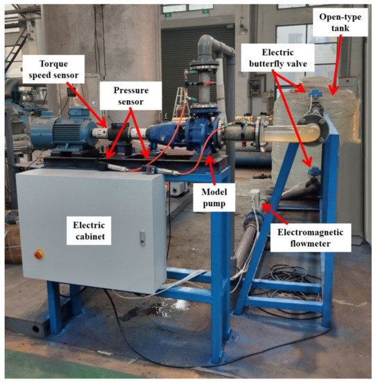
Figure 3.
Centrifugal pump performance test unit.
Table 3.
Configurations of instrument and equipment.
Figure 4 demonstrates the comparison performance characteristics of model pumps with an elbow inlet and straight pipe. Based on the straight pipe inlet, the head is 18.2 m, pump efficiency is 61.4%, and the necessary cavitation allowance is 2.52 m under the rated flow (25 m3/h). Moreover, under the 25 m3/h condition, the head of the model pump with an elbow inlet is 16 m, the efficiency is 53.2%, and the necessary cavitation allowance is 3.32 m. It can be seen that the elbow inlet causes the pump head to decrease by about 10%, the efficiency to decrease by 8%, and the necessary cavitation allowance to increase by more than 0.8 m. The test results show that the non-uniform inflow has an obvious impact on the performance characteristics of the centrifugal pump.
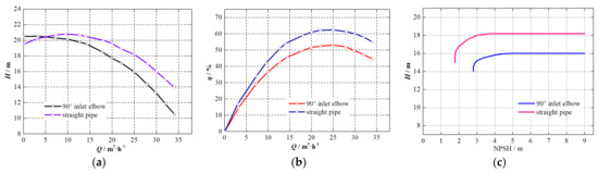
Figure 4.
Comparison performance characteristics of model pumps with elbow inlet and straight pipe. (a) H-Q curve. (b) η-Q curve. (c) cavitation curve.
2.3. CFD Methodology
The numerical simulations for centrifugal pumps are applied to obtain the pump performance in the orthogonal experiment. The entire computational domain of centrifugal pumps is shown in Figure 5a, including impeller passage, volute, and the extension of inlet and outlet. The hexahedral mesh is generated for each independent domain as shown in Figure 5b,c. The mesh density is also studied to verify the independent of element number for the solution. Figure 6 exhibits that the solution independent of the mesh with significant computational saving is provided by the meshes with 1.1 million grid points according to the pump head at the rated condition. The grid cell size meets the requirements of the large eddy simulation [18].
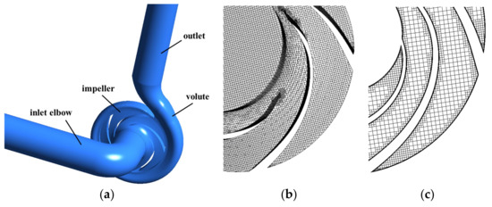
Figure 5.
Computational domain. (a) domain composition. (b) volume grids. (c) surface grid.
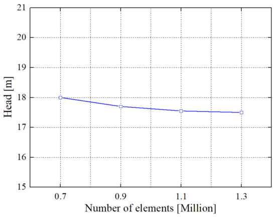
Figure 6.
Mesh independence analysis.
Based on the OpenFOAM platform, the large eddy simulation approach is used to simulate the pump performance characteristics in the paper. The inlet boundary condition is set to “velocity” with the accurate velocity component on the basis of the pump operation condition. The outlet boundary condition is set to “outflow”. Figure 7 reveals simulated pump performance characteristics compared with tested results by the experiment system of 2.2. The simulated head is 17.5 m, and the efficiency is 57%. The simulated head is 1.5 m higher than the test result, while the efficiency is 3.8% higher, as shown in Table 4. There is a little error between the simulation results and the tested data, which is caused by the processing and installation of the prototype pump.
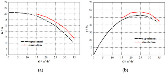
Figure 7.
Comparison between simulated and tested performance characteristics of model pump. (a) H-Q curve. (b) η-Q curve.
Table 4.
Absolute errors between experiment and simulation.
3. Parametric Orthogonal Analysis
3.1. Orthogonal Experimental Design
The orthogonal experimental design is used to study the primary and secondary order of geometric parameters of the centrifugal pump under non-uniform elbow inflow, to judge the significance of each factor on the pump efficiency, and to prepare sample points for further GA_PSO optimization. Eight dimensionless factors for the centrifugal pump are selected in the orthogonal experiment, and their specific definitions are shown in the following entry (1)–entry (8). Each factor contains three levels as shown in Table 5.
Table 5.
Orthogonal factor levels.
(1) radius ratio of elbow inlet x1.
The elbow inflow characteristics depend on the pipe parameter. The 90° elbow inlet shape is mainly determined by pipe diameter D0 and elbow curvature radius R.
(2) blade inlet angle factor x2.
For the centrifugal pump under non-uniform elbow inflow, the blade inlet angle β1 is the most important geometric parameter of the pump impeller. The reasonable blade inlet angle is able to reduce the inflow impact loss and ensure the pump cavitation performance. The x2 is defined to evaluate the blade inlet angle without affecting the direct cognition of the engineering designer to the blade inlet angle.
(3) blade number factor x3.
An impeller blade is the key component of a centrifugal pump to increase the fluid energy. Generally, the increase of blade number can improve the flow structure and appropriately increase the pump head. However, the increase of the blade number will reduce the flow passage area and increase the blade friction loss, which will not only reduce the pump efficiency, but also worsen the impeller cavitation performance.
where Z is the blade number.
(4) blade wrap angle factor x4.
The blade wrap angle φ is the included angle from the connecting line between the inlet edge and the circle center to the connecting line between the outlet edge and the circle center. When the wrap angle is appropriately increased, the blade profile is closer to the flow streamline shape to reduce the hydraulic loss in the blade passage and increase the pump head.
(5) blade outlet angle factor x5.
The larger the blade outlet angle β2 is, the bigger the circumferential component of impeller outlet velocity is, so that the pump head is raised.
(6) impeller outlet diameter factor x6.
The impeller outlet diameter d2 determines the pump head under the pump-shut condition, and has a certain impact on the impeller work capacity and shaft power.
where D1 is the volute base circle diameter.
(7) blade outlet width factor x7.
The blade outlet width b2 has a certain influence on the shape of the pump head-flowrate curve, and its decrease will eliminate the pump head hump or increase the curve slope.
where b3 is the volute inlet width.
(8) flow area ratio x8.
The flow area ratio of a centrifugal pump refers to the ratio of the flow area at the impeller outlet to the volute throat area. It is found that the flow, head, efficiency and shaft power of centrifugal pumps are closely related to the flow area ratio which is an important basis for the matching degree of the impeller and volute [19].
where Ft is the volute throat area. δ2 is the circumferential length at the blade outlet, , S2 is the blade thickness at the impeller outlet.
The interaction between factors is not considered in the orthogonal array, which will cause some random errors. The vacant column with no contributing factors is arranged for the error analysis, and guarantees the reliability of the experimental result. The orthogonal array of L27(313) is selected in this study, based on the orthogonal experimental requirements of 8 factors and 3 levels. The whole experimental arrangement, including 27 times, is presented in Table 6. The 3D models for the experimental objects in Table 5 are shown in Figure 8.
Table 6.
Orthogonal experiment schemes.
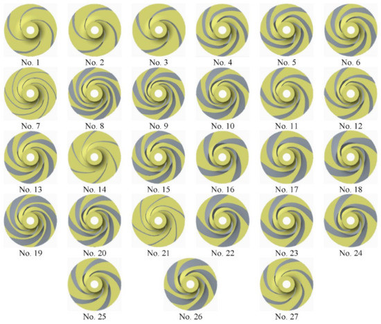
Figure 8.
3D models of 27 impellers from the orthogonal test.
3.2. Orthogonal Experiment Result Analysis
The orthogonal experiment results for the centrifugal pump with an elbow inlet are obtained by numerical simulation, the pump simulated head and efficiency of prototype pump are taken as the optimization targets. The scheme with better performance is preliminarily explored by simulated performance comparison, and then simulated results of typical scheme are verified by some entity tests.
The pump simulated heads and efficiencies of 27 schemes under the rated condition are shown in Table 7. The pump head of scheme 9 is the highest, while that of scheme 10 is the lowest. The biggest increase of the head is 8.7 m. The scheme 16 has the highest pump efficiency, while the efficiency of scheme 10 is the lowest. The maximum variable of the pump efficiency in the orthogonal experiment is 11.2%.
Table 7.
Simulated performances of pump orthogonal schemes.
The average value of pump efficiencies under each factor is calculated to obtain the influence of various factors and levels on the efficiency. Km is defined as the sum of test targets (pump efficiency values) at the mth level for a certain factor, and then km is defined as the mean value of Km. The value of km indicates that the mth level for a certain factor is either a superior level or an inferior level. R is defined as the range for the certain factor in Equation (10), which reveals the fluctuation amplitude of test target (pump efficiency) with the level variation of this factor. The bigger the value of R is, the greater the effect of this factor on the target, that is, the decreasing order of the R values is the primary and secondary order for factors.
The range analysis for the calculation results of the orthogonal schemes are shown in Table 8. I is the vacant column, and the range of vacant column is the error limit. If the range of a factor is greater than that of the vacant column, which indicates that this factor has an impact on the test target. Table 9 demonstrates the effects of factors on the pump efficiency from major to minor sequences. The blade inlet angle is the major factor, which is the most important parameter to match the non-uniform inflow. The impeller outlet diameter is the key parameter to improve the work ability of the impeller. The flow area ratio is composed of impeller outlet diameter, blade number, blade outlet width, volute throat area, and blade thickness, which indicates the matching relationship of impeller and volute. The radius ratio of the elbow inlet determines the flow structure of non-uniform inlet flow, and its variation has a certain impact on the pump efficiency based on the orthogonal result. The relations between pump efficiencies and factors are shown in Figure 9. It clearly presents the effects of factors on the pump efficiency and the trend of efficiency variation with three levels of the factor. To take factor A, for example, the efficiency of level A2 is the highest, while that of level A3 is the lowest. The efficiency of level A1 is slightly higher than that of level A3. The efficiency variations by factor B, factor F and factor H are the largest, while that by factor C and factor G are the smallest.
Table 8.
Range analyses of simulated results.
Table 9.
Sequence among factors affecting pump efficiency.
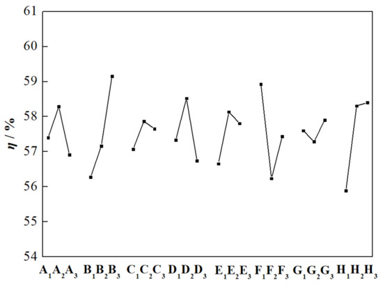
Figure 9.
Relation between factor and efficiency.
3.3. Flow Characteristics of Typical Scheme Pump
The blade inlet angle is the major factor which affects the performance characteristics of centrifugal pumps under non-uniform elbow inflow. In order to further analyze the effects of factor B in the orthogonal experiment, the inner flow features of centrifugal pumps at different levels are contrastively studied. Considering the impeller structure with different blade numbers, the pump schemes with B factors of level 1 and level 3 are chosen as the research objects based on the impeller with four blades, the impeller with five blades and the impeller with six blades, respectively, as shown in Table 10.
Table 10.
Schemes with factor B.
Obvious high pressure area and low pressure area are existed at the inlet of the blade passage, the area number is consistent with pump blade number, as exhibited in Figure 10, Figure 11 and Figure 12. This phenomenon illustrates that flow structure in the blade passage is mainly determined by pump blade feature. When the fluid enters the blade passage from the round pipe, the flow is divided by the inlet edge of the blade. The blade inlet angle is difficult to fully match the inflow angle at the different radial sections of the pump impeller, which results in flow hysteresis. The pressure of the fluid entering the blade passage in advance increases, while the fluid delayed in entering the passage forms the low-pressure area. However, flow characteristics in the blade passage of the pump with the factor B level changing are semblable as shown in Figure 13, Figure 14 and Figure 15.
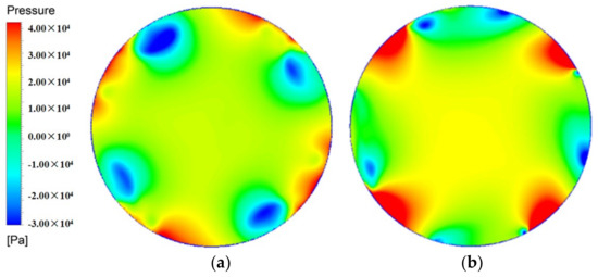
Figure 10.
Blade inlet section of 4-blades pump of (a) scheme 2 and (b) scheme 16.
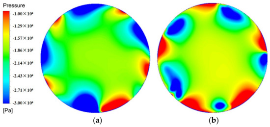
Figure 11.
Blade inlet section of 5-blades pump of (a) scheme 11 and (b) scheme 25.
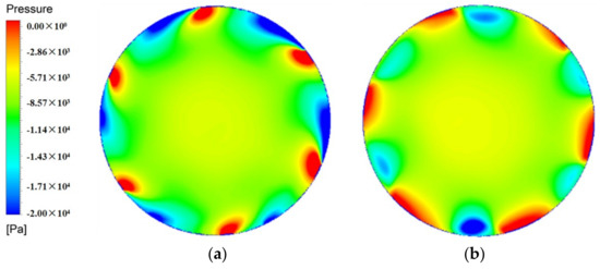
Figure 12.
Blade inlet section of 6-blades pump of (a) scheme 20 and (b) scheme 7.
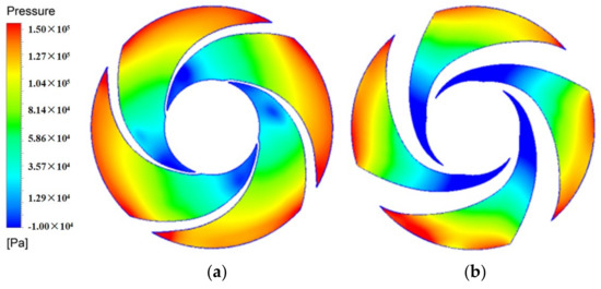
Figure 13.
Impeller meridian plane of 4-blades pump of (a) scheme 2 and (b) scheme 16.
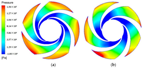
Figure 14.
Impeller meridian plane of 5-blades pump of (a) scheme 11 and (b) scheme 25.
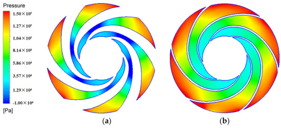
Figure 15.
Impeller meridian plane of 6-blades pump of (a) scheme 20 and (b) scheme 7.
3.4. Performance Test of Typical Scheme Pump
In the orthogonal experiment, the scheme 16 pump has the highest efficiency and the scheme 9 pump has the highest head. The scheme 16 impeller has four blades and the scheme 9 impeller has six blades. The efficiency of the scheme 24 pump is the lowest in the four-blades schemes and the efficiency of the scheme 19 pump is the lowest in the six-blades schemes. Comparing with scheme 24 and scheme 19, the blade inlet angle of scheme 16 and scheme 9 are bigger. The flow area ratio and the blade outlet width are also a little bigger as illustrated in Table 11.
Table 11.
Main geometric parameters of typical impellers.
In order to verify the accuracy of numerical simulation, scheme 9 pump and scheme 16 pump are physically processed to test the performance characteristics and pump cavitation. The entities of two impellers are processed by the rapid prototyping technology using ABS resin material, as shown in Figure 16. Pump tested performances of scheme 9 and scheme 16 at the rated condition of 25 m3/h are presented in Table 12. According to Figure 17 and Figure 18, the tested head of the scheme 9 pump is 2.5 m lower than the simulated one and the tested efficiency is 4.1% lower than the simulated one. Meanwhile, the tested head of the scheme 16 pump is 2.6 m lower than the simulated one and the tested efficiency is 3.6% lower than the simulated one. The error between the tested performance and the simulated one is acceptable, which illustrates that the simulated performance characteristics of the orthogonal scheme pumps is reliable. Figure 19 shows the comparison of cavitation tested results among the scheme 9 pump, scheme 16 pump and original pump. The cavitation performance of the scheme 9 pump or scheme 16 pump is better than that of the original pump, this is because of the adoption of the blade inlet angle with level 3. The phenomenon shows that the blade inlet angle is appropriately increased to improve the cavitation performance of centrifugal pump with elbow inlet.
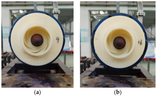
Figure 16.
Rapid prototyping impellers of (a) scheme 9 and (b) scheme 16.
Table 12.
Tested performances of scheme 9 pump and scheme 16 pump under the condition of 25 m3/h.
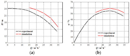
Figure 17.
Scheme 9 pump performance. (a) H-Q curve. (b) η-Q curve.
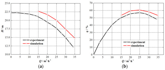
Figure 18.
Scheme 16 pump performance. (a) H-Q curve. (b) η-Q curve.
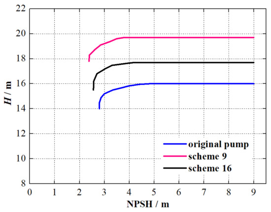
Figure 19.
Cavitation performances of scheme 9 pump and scheme 16 pump.
4. GA_PSO Optimization Design
4.1. GA_PSO Algorithm
The mechanical learning algorithm is often used in the optimization design of the mechanical structure [20]. In the mathematical model of the particle swarm optimization (PSO) algorithm, the total number of particles in a space is set as S, the flight speed of the ith particle is set as Vi, and the position of the ith particle is set as Xi. The individual optimal solution Pbesti is found by each particle and the group optimal solution Gbest is gained by the group at the time of t, which is obtained by comparing the fitness value fi at the historical time. Then, the velocity and position of the particle are updated by respectively particle velocity update equation and position update equation as shown in Equations (11) and (12). However, the particle easily falls into the local optimal solution, and the convergence speed of the simulation is slow in the later stage.
where ω is the inertia weight. c1 or c2 is the learning factor, which is used to adjust the maximum step size. r1 or r2 is a random number uniformly distributing in [0, 1].
When the intelligent optimization algorithm is used to solve the engineering problem, it is necessary to consider global optimization and local optimization, meanwhile, the global optimal solution is obtained as quickly as possible. In order to ensure that the PSO-calculation result avoids falling into the local optimization, genetic algorithm (GA) is applied to optimize the PSO algorithm. A series of genetic operations, such as selection, crossover and mutation in genetic algorithm, are introduced into the PSO algorithm. In the iterative process, a specified number of particles are selected as the parent particles according to the hybridization probability pc. The parent particles are hybridized in pairs to generate offspring particles, and the newly generated offspring particles continue to replace the parent particles, so as to make the particles trapping in the local optimization jump out. The position and velocity update equations of offspring particles are presented in Equations (13) and (14).
where child(V) and child(X) represent the velocity and position of the offspring particle respectively, parent(V) and parent (X) represent the velocity and position of the parent particle respectively, pc is a random number in [0, 1].
4.2. Optimal Design for Centrifugal Pump under Non-Uniform Elbow Inflow
The original pump is optimized by the GA_PSO algorithm based on the orthogonal experiment results. The pump efficiency was taken as the optimization objective, and the eight main parameters of centrifugal pump in the chapter of 3.1 were served as the optimization factors. The GA_PSO algorithm was used to seek the optimal parameter combination on the basis of the database in Table 7. Figure 20 exhibits the fitness iteration curve of the optimization process. It is seen that the fitness basically remains unchanged after the evolution to 20 generations. The optimization system tends to be stable and has good iterative convergence. The main parameters of the optimized pump with elbow inlet are shown in Table 13.
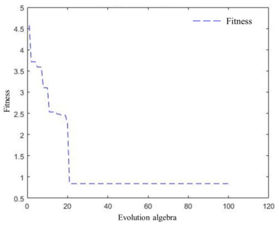
Figure 20.
GA_PSO fitness curve.
Table 13.
Optimized parameters of centrifugal pump with elbow.
The optimized impeller is processed by the rapid prototyping technology using ABS resin material, as Figure 21 shows. The performance characteristics of the optimized pump are tested, and then compared with that of the original pump (see Figure 22). Under the rated flow (25 m3/h), the head and the efficiency of the optimized pump are 18 m and 57.9%, respectively. The efficiency of the optimized pump is 4.7% higher than that of the original pump. Moreover, the necessary cavitation allowance of the optimized pump is 2.69 m and reduces by 0.63 m compared with the original pump. The performance tests demonstrate that the performance of the optimized pump with an elbow inlet is significantly improved. Based on the orthogonal experimental design and GA_PSO optimal design, the accuracy and feasibility of the optimization method for centrifugal pump with elbow inlet are proved.
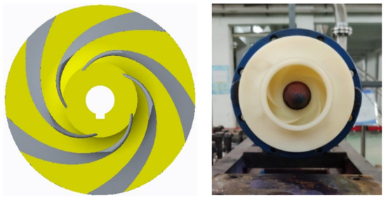
Figure 21.
Optimized impeller.
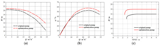
Figure 22.
Tested performance comparison between pumps before and after GA_PSO optimization. (a) H-Q curve. (b) η-Q curve. (c) cavitation curve.
5. Conclusions
The orthogonal experiment and the GA_PSO algorithm were used to improve the head and efficiency of a centrifugal pump with an elbow inlet based on the method combining numerical simulation and prototype experiment in this paper. The research results are as follows:
- (1)
- The pump performance experiment shows that the elbow inlet causes the pump head to decrease by about 10% and the efficiency to decrease by 8%, compared with the centrifugal pump with a straight pipe inlet.
- (2)
- The blade inlet angle is the major factor in matching the non-uniform inflow and reducing the flow loss in the impeller inlet to contribute to enhancing the pump performance and cavitation characteristics by the orthogonal experiment. The impeller outlet diameter is the key parameter to improving the work ability of the impeller. The flow area ratio indicates the matching relationship between impeller and volute.
- (3)
- The PSO algorithm is optimized by integrating GA, which ensures that the PSO calculation result avoids falling into the local optimization and the global optimal solution is obtained as quickly as possible. The centrifugal pump with an elbow inlet is optimally designed by the GA_PSO algorithm. The radius ratio of elbow inlet is 1.4, and the blade inlet angle is 25°. According to the performance test results, the efficiency of the optimized pump is 4.7% higher than that of the original pump, meanwhile, the necessary cavitation allowance reduces by 0.63 m compared with original pump.
Author Contributions
Data curation, Y.Y. and L.T.; Funding acquisition, Y.Y.; Investigation, R.J. and Y.L.; Methodology, L.T.; Project administration, Y.Y.; Writing-original draft, Y.Y. and L.T. All authors have read and agreed to the published version of the manuscript.
Funding
This research was funded by the Natural Science Foundation of Jiangsu Province of China for Young Scholars (Grant No. BK20210883).
Conflicts of Interest
The authors declare no conflict of interest.
References
- Mitsukiyo, M.; Naomichi, H. Swirling flow in suction pipe of centrifugal pumps (1st report, distribution of velocity and energy). Bull. JSME 1966, 9, 328–337. [Google Scholar]
- Noorani, A.; Khoury, G.K.E.; Schlatter, P. Evolution of turbulence characteristics from straight to curved pipes. Int. J. Heat Fluid Flow 2013, 41, 16–26. [Google Scholar] [CrossRef]
- Oyelade, A.O.; Ikhile, O.G.; Oyediran, A.A. Stability and dynamics of a slightly curved viscoelastic pipe resting on linear and nonlinear viscoelastic foundation. Iran. J. Sci. Technol. Trans. Civ. Eng. 2022, 46, 1329–1343. [Google Scholar] [CrossRef]
- Alvarado-Rodríguez, C.E.; Sigalotti, L.D.G.; Klapp, J.; Fierro-Santillán, C.R.; Aragón, F.; Uribe-Ramírez, A.R. Smoothed particle hydrodynamics simulations of turbulent flow in curved pipes with different geometries: A comparison with experiments. J. Fluids Eng. 2021, 9, 091503. [Google Scholar] [CrossRef]
- Van Esch, B.P.M. Performance and radial loading of a mixed—Flow pump under non—Uniform suction flow. J. Fluids Eng. 2009, 131, 051101. [Google Scholar] [CrossRef]
- Hu, P.X.; Zangeneh, M. CFD calculation of the flow through a water—Jet pump. In International Conference on Waterjet Propulsion III; RINA: Gothenburg, Sweden, 2001; pp. 1–10. [Google Scholar]
- Jaiswal, A.K.; Siddique, M.H.; Paul, A.R.; Samad, A. Surrogate-based design optimization of a centrifugal pump impeller. In Engineering Optimization; Taylor & Francis: Oxfordshire, UK, 2021. [Google Scholar]
- Alawadhi, K.; Alzuwayer, B.; Mohammad, T.A.; Buhemdi, M.H. Design and optimization of a centrifugal pump for slurry transport using the response surface method. Machines 2021, 9, 60. [Google Scholar] [CrossRef]
- Yuan, Y.; Yuan, S.Q.; Tang, L.D. Investigation on the effect of complex impeller on vibration characteristics for a high-speed centrifugal pump. Proc. Inst. Mech. Eng. Part A J. Power Energy 2020, 234, 611–624. [Google Scholar] [CrossRef]
- Guo, S.; Yao, C. Non-uniform distribution of water-jet inlet flow field. In Proceedings of the 2010 IEEE International Conference on Information and Automation, Harbin, China, 20–23 June 2010; pp. 1452–1456. [Google Scholar]
- Mark, E.A.; David, E.W.; Charles, C.A. An evaluation of reducing elbow characteristics versus velocity distribution at the pump inlet. In World Environmental and Water Resources Congress 2014: Water without Borders; ASCE: Reston, VA, USA, 2014; pp. 1207–1215. [Google Scholar]
- Huang, R.F.; Wang, Y.W.; Du, T.Z.; Luo, X.W.; Zhang, W.; Dai, Y.X. Mechanism analyses of the unsteady vortical cavitation behaviors for a waterjet pump in a non-uniform inflow. Ocean. Eng. 2021, 233, 108798. [Google Scholar] [CrossRef]
- Hajnayeb, A. Cavitation analysis in centrifugal pumps based on vibration bispectrum and transfer learning. Shock. Vib. 2021, 2021, 6988949. [Google Scholar] [CrossRef]
- Duerr, P.; Ellenrieder, K.D.V. Scaling and numerical analysis of non-uniform waterjet pump inflows. IEEE J. Ocean. Eng. 2015, 40, 701–709. [Google Scholar] [CrossRef]
- Motley, M.R.; Savander, B.R.; Young, Y.L. Influence of spatially varying flow on the dynamic response of a waterjet inside an SES. Int. J. Rotating Mach. 2014, 2014, 275916. [Google Scholar] [CrossRef] [Green Version]
- Yuan, Y.; Yuan, S.Q.; Tang, L.D. Numerical investigation on the mechanism of double-volute balancing radial hydraulic force on the centrifugal pump. Processes 2019, 7, 689. [Google Scholar] [CrossRef] [Green Version]
- Bulten, N.W.H.; Van Esch, B.P.M. Fully transient CFD analyses of waterjet pumps. Mar. Technol. 2007, 44, 185–193. [Google Scholar] [CrossRef]
- Cui, B.L.; Zhang, Y.B.; Huang, Y.K. Analysis of the pressure pulsation and vibration in a low-specific-speed centrifugal pump. J. Fluids Eng. 2021, 143, 021201. [Google Scholar] [CrossRef]
- Yuan, S.Q. Low Specific Speed Centrifugal Pump Theory and Design; Machine Press: Beijing, China, 1997. [Google Scholar]
- Das, A.; Das, S.R.; Panda, J.P.; Dey, A.; Gajrani, K.K.; Somani, N.; Gupta, N.K. Machine learning based modelling and optimization in hard turning of AISI D6 steel with newly developed AlTiSiN coated carbide tool. arXiv 2022, arXiv:2202.00596. [Google Scholar]
Publisher’s Note: MDPI stays neutral with regard to jurisdictional claims in published maps and institutional affiliations. |
© 2022 by the authors. Licensee MDPI, Basel, Switzerland. This article is an open access article distributed under the terms and conditions of the Creative Commons Attribution (CC BY) license (https://creativecommons.org/licenses/by/4.0/).