Review

A Review of the Preparation, Machining Performance, and Application of Fe-Based Amorphous Alloys

1
Shenzhen Key Laboratory of High Performance Nontraditional Manufacturing, College of Mechatronics and Control Engineering, Shenzhen University, Nanhai Ave 3688, Shenzhen 518060, China
2
Guangdong Provincial Key Laboratory of Electromagnetic Control and Intelligent Robots, College of Mechatronics and Control Engineering, Shenzhen University, Nanhai Ave 3688, Shenzhen 518060, China
3
School of Mechanical and Electrical Engineering, Shenzhen Polytechnic, Shenzhen 518055, China
*
Author to whom correspondence should be addressed.
Processes 2022, 10(6), 1203; https://doi.org/10.3390/pr10061203
Submission received: 10 May 2022 / Revised: 27 May 2022 / Accepted: 7 June 2022 / Published: 16 June 2022

Abstract

:
Amorphous alloy is an emerging metal material, and its unique atomic arrangement brings it the excellent properties of high strength and high hardness, and, therefore, have attracted extensive attention in the fields of electronic information and cutting-edge products. Their applications involve machining and forming, make the machining performance of amorphous alloys being a research hotspot. However, the present research on amorphous alloys and their machining performance is widely focused, especially for Fe-based amorphous alloys, and there lacks a systematic review. Therefore, in the present research, based on the properties of amorphous alloys and Fe-based amorphous alloys, the fundamental reason and improvement method of the difficult-to-machine properties of Fe-based amorphous alloys are reviewed and analyzed. Firstly, the properties of amorphous alloys are summarized, and it is found that crystallization and high temperature in machining are the main reasons for difficult-to-machine properties. Then, the unique properties, preparation and application of Fe-based amorphous alloys are reviewed. The review found that the machining of Fe-based amorphous alloys is also deteriorated by extremely high hardness and chemical tool wear. Tool-assisted machining, low-temperature lubrication assisted machining, and magnetic field-assisted machining can effectively improve the machining performance of Fe-based amorphous alloys. The combination of assisted machining methods is the development trend in machining Fe-based amorphous alloys, and even amorphous alloys in the future. The present research provides a systematic summary for the machining of Fe-based amorphous alloys, which would serve as a reference for relevant research.

1. Introduction

Amorphous alloy is a functional material emerging in the 21st century, also known as metallic glass (MG), which has a unique internal structure with long-range disorder and short-range order in the arrangement of atoms in the 3D space [1], which does not have the grain boundaries in ordinary metallic materials and has the properties of both metal and glass. The arrangement of amorphous alloys can be divided into short-range with regular clusters, medium-range, and long-range with irregular arrangement of clusters, as shown in Figure 1. Amorphous alloys have no fixed melting and boiling points and are isotropic [2], which is distinctly different from crystalline materials. The special atomic structure results in amorphous alloys having excellent properties, such as lower density, high strength, high hardness, and high resistivity, as well as excellent friction resistance, corrosion resistance, and soft magnetic properties, thus, amorphous alloys have received widespread attention.
For a long time, the low glass-forming ability (GFA) limited the preparation of amorphous alloys until Greer [5] was the first to propose the famous confusion principle, which showed that more components could increase the GFA of amorphous alloys. The confusion principle has helped the emergence of numerous amorphous alloys. Amorphous alloys can be divided into different types according to the main forming elements, such as Fe-based, Pd-based, Zr-based, etc. Each type of amorphous alloy has unique properties. Among the many amorphous alloys, Fe-based amorphous alloys have received a lot of attention from researchers because of their excellent soft magnetic properties, high corrosion resistance, high strength and hardness, and high wear resistance [6]. Fe-based amorphous alloys have an elastic modulus similar to conventional stainless steel, yet are 3–4 times stronger and harder than ultra-high-strength steels [7], as shown in Figure 2. The high strength and high hardness of Fe-based amorphous alloys bring many benefits. Meanwhile, it also limits the machining and forming of Fe-based amorphous alloys. General machining methods cannot make Fe-based amorphous alloys obtain ideal machining performance. Therefore, a machining technology with good machining ability is needed to solve the machining and preparation of Fe-based amorphous alloys. In the field of machining, ultra-precision machining technology occupies a very important position in the manufacture of cutting-edge products and modern weapons. As an important ultra-precision machining method, single-point diamond turning (SPDT) can machine some brittle or difficult-to-machine materials into high-hardness workpieces with optical surface quality in the case of assisted machining [8,9]. Machining Fe-based amorphous alloys with SPDT technology is a good choice. However, chemical wear due to the chemical affinity between diamond tools and Fe-based amorphous alloys cannot be ignored.
With its excellent soft magnetic properties, Fe-based amorphous alloys have been widely used in various electrical components, and it would be of great importance to use SPDT to achieve good machining performance. Numerous researchers have used many methods to study Fe-based amorphous alloys in an attempt to explore suitable machining methods for Fe-based amorphous alloys. For machining difficult-to-machine materials like Fe-based amorphous alloys, several non-traditional assisted machining methods have demonstrated the ability to improve their machining performance [10]. Although there is much research on Fe-based amorphous alloys, the research on machining Fe-based amorphous alloys is rather scattered, and a systematic review is needed to distill current research progress and future research directions. In the present research, the causes of difficult-to-machine Fe-based amorphous alloys and methods to improve their machining performance are reviewed to guide the subsequent research on the machining of Fe-based amorphous alloys.

2. Preparation and Properties of Amorphous Alloys

2.1. Amorphous Alloys versus Crystalline Materials

Amorphous alloys are glassy substances that are very different from crystals at the atomic level. At the macro level, amorphous alloys are also quite different from crystal metals, which is an important factor affecting the machining performance of amorphous alloys.
Firstly, amorphous alloys are sub-stable, when the temperature or pressure reaches a certain value, the amorphous state crystallizes into a crystalline state. The transition from the amorphous state to the crystalline state has a distinct crystallization peak, which can be measured with a differential thermal analyzer such as differential scanning calorimetric (DSC) [11]. In addition to DSC measurements, X-ray diffraction (XRD) analysis of amorphous alloys can also determine whether the material is in an amorphous state. The diffraction curves of amorphous alloys usually show scattered diffraction peaks (please see Figure 3e), while crystalline alloys show sharp diffraction peaks with different intensities on the diffraction curves (please see Figure 3f) [12]. Amorphous alloys crystallize during machining, which will cause some properties of amorphous alloys to be lost. However, there is a special case, the formation of nanocrystalline or amorphous/nanocrystalline composites by nano-crystallization of amorphous alloys may improve some properties of amorphous alloys [13].
Secondly, amorphous alloys are isotropic in physical properties, while crystal metals are anisotropic. Although amorphous alloys are isotropic, amorphous alloys are structurally and kinetically inhomogeneous [14,15,16]. Observation of AFM can find that the amorphous alloy has a phase shift on the nanometer scale (please see Figure 3a–c). After ultrasonic treatment, soft and hard regions appear in the amorphous alloy due to crystallization (please see Figure 3d). These are manifestations of the inhomogeneous structure of amorphous alloys. Meanwhile, amorphous alloys do not have a definite melting point [14], while crystal metals have a definite melting point at room temperature and atmospheric pressure. For example, plastics and glass, as amorphous materials, are heated to gradually soften and eventually become liquid. And amorphous alloys have a glass transition temperature point (Tg), while crystal metals do not [17].
Thirdly, when shear bands appear in the atomic structure of amorphous alloys, it will lead to fatal failure of the material, which is a fatal defect of amorphous alloys compared to crystal metal structures [18]. Therefore, the number of shear bands in amorphous alloys is also considered to be a good indicator of the intrinsic plasticity and fracture toughness of amorphous alloys [19,20,21]. In machining amorphous alloys, we need to pay attention to shear band changes. Wang et al. [22] found that the bending shear bands of amorphous alloys exhibited asymmetric orientations on the tensile and compressive sides (please see Figure 4a). Gao et al. [23] showed that radial shear bands are the result of the in-plane stress components (please see Figure 4b), while the semicircular shear bands are an artifact of stress relaxation due to the bonded interface (please see Figure 4c). The shear band of amorphous alloys can be simulated using molecular dynamics (MD). Sopu et al. [24] found through MD simulation that the shear band starts at the stress concentration at the root of the notch and extends along the plane of maximum shear stress (please see Figure 4d).

2.2. Preparation of Amorphous Alloys

In 1959, Klement et al. [25] jointly produced the first amorphous alloy Au75Si25 at Caltech. In 1969, Chen and Turnbull [26] fabricated Pd−based amorphous spheres at a critical cooling rate of 100–1000 °C s−1. Then in the 1980s, Inoue [27] and his colleagues at Tohoku University made a breakthrough in bulk metallic glass (BMG), and discovered a multi-component amorphous alloy with strong GFA. The breakthrough eliminated the need to add noble metal elements to amorphous alloys to enhance its GFA, thus, greatly enhancing the application of amorphous alloys. In 1992, Johnson and Peker [28] discovered the first commercial amorphous alloy Vit1 in some new aerospace materials. A summary of the research progress of amorphous alloys is shown in Table 1.
Amorphous alloys develop an amorphous structure by cooling the metal from the melt at a critical cooling rate below the glass transition zone. In addition to the amorphous structure obtained by rapid cooling of the liquid, it is also possible to form ordered crystalline structures and plastic crystals in the liquid cooling (please see Figure 5a). To ensure that a completely amorphous state is obtained during the preparation, a very high cooling rate (106 K/S) is required, as shown in Figure 5b. Thus, limiting the amorphous alloys to often prepare only low dimensional size alloy samples, such as powders and thin strips, and it is difficult to form BMGs with larger critical dimensions, which is the so-called poor GFA of amorphous alloys, Johnson expressed the GFA by the critical cooling rate Rc [46]:
R C = d T d t ( K / s ) = 10 D 2 ( c m )
where D is the critical size. The GFA is mainly related to two factors: the liquid phase stability of the supercooled liquid and the crystallization resistance. The supercooled liquid is stable or has a high resistance to crystallization, it tends to form glass and has a higher GFA [47]. At the same time, Turnbull [26] proposed that a decrease in the reduction of glass transition temperature Trg (the ratio of Tg to the temperature of the liquid phase line of the alloy Tl) is a good indicator of GFA. Amorphous alloys have superplastic deformability in the supercooled liquid region (between the glass transition temperature Tg and the crystallization onset temperature Tx) (please see Figure 5c), which means that viscous flow occurs when the machining temperature of the amorphous alloy exceeds the subcooled liquid region [48].
Compared with the singleness of the theoretical methods of amorphous formation, the forming methods of amorphous alloys are diverse. The classical methods for their main forming are: end-casting in copper molds, die forging, etc. [28]. Research has shown that heating amorphous alloys in a magnetic field to a softened state is a good method for forming amorphous alloys. The millisecond heating method newly studied by Johnson et al. [50] can easily make the heating rate reach 106 K/s. The supercooled liquid can pass the melting point into equilibrium at any temperature above the glass transition (please see Figure 5d), which can intervene well in the crystallization of the supercooled liquid. This forming method may become a promising method for the fabrication of strong metals [50,51]. However, this forming method is not mature at present, and machining is still an unavoidable and important forming method for amorphous alloys. Amorphous alloys are difficult to machine because of their characteristics, and various machining problems need to be solved to obtain better machining performance.

2.3. Properties of Amorphous Alloys

When amorphous alloys were first studied, researchers were drawn to them by their excellent properties, such as strength and hardness. The tensile strength of the Mg80Cu10Y10 amorphous alloy produced by Inoue et al. [52] was as high as 630 MPa at room temperature. Subsequently, Co-based amorphous alloy was found to reach a fracture strength as high as 6.0 GPa [53], which is the highest strength in metallic materials to date. Fe-based amorphous alloys have also been reported to have fracture strengths up to 3.6 GPa, which is several times higher than typical structural steel [54]. The fracture strength of Fe-based amorphous alloys is even higher than that of most materials (please see Figure 6a).
As the research on amorphous alloys progressed, more outstanding properties of amorphous alloys began to be discovered. Based on previous studies, Johnson [56] studied in 2011 to obtain Pd-based amorphous alloys with fracture toughness up to 200 MPa m1/2, which is the highest fracture toughness value of the material so far. After research, Fe-based MG has also been clearly shown to successfully remove organic matter from wastewater [57]. Fe-based amorphous alloys are known for its high corrosion resistance, and Fe-based amorphous alloys not only exhibited high corrosion resistance in conventional environments, Pratap et al. [58] further demonstrated that Fe-based amorphous alloys can still have excellent corrosion resistance under simulated body fluids. Although the surface of the Fe-based amorphous alloy is corroded in the simulated body fluids, the surface morphology does not change much (Figure 7). In addition to the excellent properties mentioned above, Fe-based amorphous alloys exhibit excellent soft magnetic properties. Yi [59] even stated that “Fe-(Al, Ga)-(Si-P-B-C) and Fe-Cu-Nb-Si-B amorphous alloy are recognized worldwide as the best comprehensive soft magnetic material”.
Obviously, amorphous alloys have many excellent properties. Amorphous alloys have some record-breaking excellent physical and chemical properties, such as strength, toughness, hardness, and modulus, which break the record for metallic materials [54,56,57,58,59,60,61,62], almost every type of amorphous alloy reaches several times the strength of the crystalline material of the same alloy family. Some amorphous alloys also have excellent soft magnetic properties, catalytic properties, and good wear resistance and are widely used in various applications [63,64]. Fe-based nano-amorphous alloys have outstanding magnetization strength and permeability (please see Figure 6b), even better than the comprehensive soft magnetic properties of silicon steel, which is an indispensable soft magnetic material in the power, electronics, and military industries. Different structural configurations exist for amorphous alloys of the same composition [65]. Therefore, the physical properties of amorphous alloys can be regulated by time and process conditions. Meanwhile, amorphous alloys have a wide range of forming compositions [66], and their structure and properties can be modulated by composition. And even amorphous alloys within the same system can possess different properties depending on their composition. For example, there are Fe-based amorphous alloys that can reach a maximum critical size of 16 mm, while there are Fe-based amorphous alloys that have poor GFA but possess excellent soft magnetic properties [67,68].
Conversely, amorphous alloys still have their own unique defects. Although in 1995 Inoue [69] reviewed the gradual appearance of amorphous alloys with great GFA in that era, the critical size of 72 mm for Pd40Cu30Ni10P20 prepared in 1997 [70] is still the largest example of the critical size in amorphous alloys today. The poor GFA of amorphous alloys have largely limited the industrial applications of amorphous alloys. Also limiting the industrial applications of amorphous alloys are their record-breaking strength and hardness, which makes most amorphous alloys have very poor macroscopic room temperature plastic deformation [54,71], making it difficult to obtain the designed shape by conventional methods in applications.

2.4. Machining Performance of Amorphous Alloys

The improved mechanical properties of amorphous alloys compared to crystal metals bring challenges in machining, such as tool wear, high machining temperature, and crystallization on the material surface [72]. Numerous experimental studies and modeling have been performed for the machining of crystalline materials to investigate the chip splitting mechanism during the cutting and machining of crystalline materials [73,74]. The study of these mechanisms plays an important role in the processing of crystal metals. However, the chip splitting mechanism of amorphous alloys is different from that of crystal metals [75], and the systematic knowledge of the machining theory of crystal metals cannot be applied to the machining process of amorphous alloys. Zhu and Fang [76] found that the amorphous alloys removal during the nano-cutting process was achieved by extrusion rather than shear. Some theoretical knowledge of the machining process of amorphous alloys are bound to help improve the machining performance of amorphous alloys. Therefore, there is an urgent need to systematically review the research on a large number of amorphous alloys.
Amorphous alloys are difficult to machine due to their hard-brittleness and sub-stable structure during machining, this does not mean that amorphous alloys cannot be machined to obtain good surface quality. Chong et al. [77] obtained a surface Ra of 6.3 nm when cutting La-based amorphous alloy. What’s more, Xiong et al. [78] obtained optical mirror surfaces during SPDT Pd-based BMG. The center area of the machined surface was relatively clean and had no irregular micro/nanostructure exists, as shown in Figure 8a. It can be determined that the Pd-based BMG remains in the amorphous state after turning (please see Figure 8b). This means that amorphous alloys can be machined without causing crystallization of the machined surface by SPDT. Xiong et al. [78] proved that amorphous alloys have the potential to obtain optical mirror surfaces through SPDT, and they also revealed that the high cutting temperature during the machining of amorphous alloys is an important factor for their difficult-to-machine qualities. In contrast, the machined surface quality of Fe-based amorphous alloys is particularly poor [79], as shown in Figure 9.
Xiong et al. [78] further showed that when the temperature of the cutting area exceeds Tg, viscous flow occurs in the cutting area, resulting in additional friction between the tool and the workpiece, and aggravating the temperature rise in the cutting area. If the temperature of the cutting area is higher than Tg for a long time, a surface oxide was generated. Meanwhile, as mentioned above, when the temperature exceeds Tg, the amorphous alloy will crystallize, thus affect the machining. Therefore, the change in temperature of amorphous alloys undercutting and whether the material undergoes crystallization have become the focus of many studies. For example, Maroju and Jin [72] found that the cutting temperature is lower than the crystallization temperature in the cutting experiment of Zr-based BMG. However, such satisfactory results were not obtained under all conditions. Bakkal et al. [80] found that at low turning speeds, the machined surface and chips did not crystallize. At high turning speeds, the BMG of the outer layer is oxidized, and the chips appears to be crystallized to different degrees, as shown in Figure 8c–f. As mentioned in Section 2.1, the formation of nanocrystalline or nanocrystalline/amorphous composites can lead to improvements in material properties. Fu et al. [81] found that high-energy ion milling can make BMG form nanocrystalline phases. When crystallization cannot be avoided in the machining of amorphous alloys, the formation of nanocrystalline phases may be a good choice.
The cutting temperature in the machining of amorphous alloys also affects the machining performance of amorphous alloys in terms of the shear band. Zhang et al. [82] expressed that the deformation of BMG after turning was at least partly caused by the adiabatic shear temperature rise. Increased shear speed leads to significant melting of the workpiece surface due to temperature rise in the shear zone. The melting phenomenon caused by the high temperature in the shear zone is also manifested in the chips, and the melting of the chip surface is more serious at higher shear rates, as shown in Figure 10. Although it is confirmed that the temperature rise in the shear zone affects the machining performance of amorphous alloys, in some cases the temperature rise can actually improve the properties of amorphous alloys. Basak and Zhang [83] found that the surface temperature rise of amorphous alloys caused by contact sliding friction heat increases the hardness of MG.

3. Preparation, Machining, and Application of Fe-Based Amorphous Alloys

Among the many studies on amorphous alloys mentioned above, it is not difficult to find a special presence among the many amorphous alloy systems, Fe-based amorphous alloy. Fe-based amorphous alloys have far superior chemical properties [84,85], physical and mechanical properties [86,87] than ordinary crystalline alloys, such as high strength, high hardness, low elastic modulus, corrosion resistance, and excellent soft magnetic performance [88], and also has the advantages of low production cost [89], aroused great interest of people [47,90]. However, it is more difficult to obtain ideal surface quality than other amorphous alloys. It is necessary to explore more suitable machining methods for Fe-based amorphous alloys based on the machining of amorphous alloys.

3.1. Preparation and Application of Fe-Based Amorphous Alloys

In 1988, Yoshizawa et al. [91] added a small amount of Cu and Nb to Fe-Si-B amorphous alloy and obtained Fe-Si-B-Nb-C Fe-based nanocrystalline soft magnetic alloy after crystallization and annealing, which has excellent soft magnetic properties and gained wide attention. In late 1989, Prof. A. Inoue [92] proposed the principles contributed greatly to the emergence of many Fe-based amorphous alloys that followed. In 1995, Inoue [93] and coworkers synthesized the first Fe-based BMG with a diameter of 1 mm in the Fe-Al-Ga-P-C-B alloy system by using the copper casting technique. Since the 21st century, research on amorphous alloys has developed rapidly, and Fe-based amorphous alloys have gained a lot of breakthroughs along with the development trend. Although the domestic-related research started late, also made certain achievements, the most representative one is Chen et al. [67] developed Fe41Co7Cr15Mo14C15B6Y2 amorphous alloy with a critical size of 16 mm.
Although under the guidance of Inoue’s numerous research achievements, the critical size of Fe-based amorphous alloys have been gradually broken through, and the disadvantage of poor GFA has been alleviated in some applications, there is still a serious problem in the research of Fe-based amorphous alloys, which is room temperature embrittlement [94]. Fe-based amorphous alloys are widely used due to their many excellent properties. For example, Fe-based amorphous strips [95] are used in transformers and cores for motors because of their excellent electromagnetic properties; Fe-based amorphous coatings [96] are widely used in the protection of equipment in the petroleum and electric power industries for their excellent corrosion resistance, wear, and high temperature; Fe-based BMG [67] has been widely used as a special structural material in the military industry and other fields because of its high strength and high hardness mechanical properties; compared to Zr-based and Pd-based BMGs, Fe-based BMGs have superior overall performance, and their high thermal stability and low thermal conductivity can be used in building structures, refrigeration, insulation devices in liquefied petroleum engineering technologies, and highly sensitive precision micro-components [97]. The thermal conductivity of Zr-based amorphous alloys and Pd-based amorphous alloys is already lower than that of most materials (Figure 11). Although the extremely low thermal conductivity of Fe-based amorphous alloys makes it advantageous in some fields, it also makes it difficult to dissipate the machining heat of Fe-based amorphous alloys.
Figure 12 shows some applications cases of Fe-based amorphous alloy. With excellent soft magnetic properties, powder cores made of Fe-based amorphous alloys with higher efficiency and less heat generation are used for power inductors in laptops (please see Figure 12a). Combined with the excellent soft magnetic properties and extremely high fracture strength of Fe-based amorphous alloys, they are applied as torsion bars to help achieve larger scanning angles (please see Figure 12b). In addition to having extremely high fracture strength, Fe-based amorphous alloys have excellent mechanical properties and can be used in a variety of wires (please see Figure 12d) [93]. Fe-based amorphous alloys also have good catalytic performance and can be used for various wastewater purification applications (please see Figure 12c) [98]. It can be seen that Fe-based amorphous alloys have a very wide range of industrial applications and good prospects for development.

3.2. Machining of Fe-Based Amorphous Alloys

Machining is an important forming method for Fe-based amorphous alloys. Turning and milling are the most common machining methods, and the machining of Fe-based amorphous alloys is often inseparable from these two machining methods. Fang [79] performed two-dimensional cutting of Fe-Si-B amorphous alloy and concluded that the development of shear bands leads to the formation of macroscopic dislocations and cracks in the workpiece, and a work-hardening layer appears in the bottom layer after cutting, making its magnetic properties significantly degraded. Wang [100] conducted cutting experiments on Fe-Al-Cr-B-Si-Nb amorphous alloy and found that the crystallization of chips was up to 52.5% with serious crystallization after increasing the cutting speed and depth of cut. In the above-mentioned cutting experiments on Fe-based amorphous alloys, it was found that the properties of Fe-based amorphous alloys deteriorated after cutting. However, in some experiments of milling, Fe-based amorphous alloys performed well after milling. Fan et al. [101] performed experiments on Fe80B20 by mechanical milling and found that milling induced magnetic anisotropy in the workpiece, which may be attributed to a relief of the induced stresses after bulk crystallization has occurred. Nakao and Fang [102] used their previous experience in milling Fe-Si-B amorphous alloy to take advantage of the brittleness of nanoscale grains in the transition zone for high-speed milling and successfully obtained a better-milled surface. Nakao and Fang found that after increasing the milling speed, the maximum grain and area fraction increased with the rapid growth of nanocrystals as the cutting temperature increased, as shown in Figure 13a. Nakao’s case of using the properties of nanocrystals in the transition zone to help to machine and thus obtaining a better-machined surface also confirms the feasibility of obtaining a better-machined surface by removing the surface crystallized material.
Although some basic machining methods such as turning and milling are sufficient for most machining needs, in practice, some materials require special machining to meet the requirements. Since the invention of the first laser by C.K.N. Patel in 1964, laser machining has received a lot of attention a long time and is now widely used as a special machining technology in various fields such as micromachining, marking, cutting, and welding. Quintana et al. [104] performed laser machining of Fe81B13.5Si3.5C2 amorphous alloy and the experimental results showed that short-pulse laser machining and long-pulse laser machining are promising techniques for micromachining amorphous alloys. Because they can make amorphous alloys avoid crystallization during machining, thereby ensuring the characteristics of amorphous alloys. Comparing the SEM image of the Fe-based amorphous alloy after laser processing with the SEM image of the polycrystalline Ni-based alloy after laser processing, after testing, it is confirmed that the Fe-based amorphous alloy has no crystallization phenomenon after laser machining. EDM is also a typical special machining technology, which uses thermal energy to remove materials, and its machining ability is not affected by the hardness and strength of the material. The disadvantage of EDM is the poor quality of the machined surface. Tsui et al. [103] used ultrasonic vibration-assisted EDM and added conductive aluminum powder to machine Fe-based amorphous alloys, and the workpiece did not crystallize after machining, as shown in Figure 13c,d. Although there are craters on the machined surface (please see Figure 13c), no crystallization occurred (please see Figure 13d). However, many machining methods cannot make amorphous alloys avoid crystallization during machining like laser machining and EDM. He et al. [105] showed that compression machining of Fe93P10C7 amorphous alloy accelerates its crystallization. Some researchers take advantage of this accelerated crystallization phenomenon.
Nanocrystalline is a special form of amorphous alloy. Mechanical ball milling has been confirmed to make Fe-based amorphous alloys nano-crystallized, thereby improving the properties of Fe-based amorphous alloys. Ramasamy et al. [106] induced the generation of nanocrystalline α-Fe(Nb) after ball milling of Fe80Nb10B10 amorphous alloy. And they showed that the magnetic properties of mechanically induced nanocrystalline α-Fe composites were superior to those of amorphous alloys. The Fe-based amorphous alloy samples hot-pressed at 903 K (please see Figure 14b) have lower porosity and better bonding properties than those hot-pressed at 703 K (please see Figure 14a), which can reflect the good performance of nanocrystals at high temperature. For the two hot-pressed samples, only α-Fe peaks were observed, indicating that α-Fe is stable at temperatures of 703 K and 903 K, as shown in Figure 14c. The saturation magnetization of the samples under hot pressing at 703 and 903 K were 90 and 125 Am2/kg, respectively, reflecting the excellent magnetic properties of nanocrystals, as shown in Figure 14d. After high-energy ball milling of the Fe-Mo-Si-B amorphous alloy by Guo and Lu [107], the amorphous alloy was also found to generate the nanocrystalline α-Fe. Guo and Lu also showed that α-Fe has remarkable thermal stability at high temperatures. It can be seen that the nanocrystals formed during the machining of Fe-based amorphous alloys can provide some strengthening of their properties.
In most cases, Fe-based amorphous alloy will be crystallized after machining, and some scholars have studied how the crystallization affects them. Lv and Chen [108], in their study of the Fe45Cr15Mo14C15B6Y2Ni3 amorphous alloy, found that the key factor affecting the thermal conductivity of Fe-based BMG was the size and number of nanocrystals, and the thermal conductivity increased significantly after crystallization. In Section 2.4, it is mentioned that cutting temperature is an important factor affecting the machining performance of amorphous alloys. The thermal conductivity can directly affect the cutting temperature. Therefore, it may be possible to reduce the cutting temperature through the crystallization of Fe-based amorphous alloy.
SPDT is expected to achieve good machining of iron-based amorphous alloys. It is not convenient to study the cutting mechanism of amorphous alloys because Fe in Fe-based amorphous alloys can cause graphitization of diamond tools, Han et al. [109] investigated the effects of spindle speed, feed rate, and depth of cut on the machined surface of Zr-based BMGs (Table 2), as shown in Figure 15. The chip morphology at different cutting parameters showed a typical flow pattern, and the cutting morphology changed significantly in sample D with the spindle speed of 500 r/min. Experimental results by Han et al. showed that spindle speed has a greater effect on the BMG machined surface than feed rate and depth of cut, and the larger the spindle speed, the less ductile the surface. In ultra-precision turning, both diamond tools and boron nitride tools are very good and widely used tools. The use of boron nitride tools can effectively avoid chemical wear between diamond tools and Fe-based amorphous alloys. Chen et al. [110] explored the micro-machinability of amorphous alloys by ultra-precision machining of Zr-based amorphous alloys with diamond tools and boron nitride tools. They found that the BMG materials under SPDT could be removed by a ductile mode like metals rather than brittle materials. This mechanism has important implications for the use of SPDT Fe-based amorphous alloy. Fe-based amorphous alloys are machined by SPDT, which is not conducive to direct study of the mechanism, so there is little related research. However, the conclusions drawn by the above-mentioned scholars using other amorphous alloys under SPDT research can provide good help for the ultra-precision machining of Fe-based amorphous alloys.

3.3. Difficult-to-Machine Property of Fe-Based Amorphous Alloys

The difficult-to-machine property of Fe-based amorphous alloy limits its application, and study is needed of the suppression methods aimed at the causes of its being difficult to machine. Based on the characteristics of Fe-based amorphous alloys, excessive cutting forces, and high cutting temperatures occur during machining. When the cutting temperature exceeds 352 °C, the amorphous alloy will crystallize, which will have a certain negative impact on the machining process [111]. Wang [100] found that the chips eventually crystallized when cutting Fe-based amorphous alloys using cemented carbide tools. Whether it is the Fe-based amorphous alloy itself or the chips at each cutting speed, there is an obvious reduction in the area of the crystallization exothermic peak, which is a signal of crystallization, indicating that the workpiece is crystallized seriously in the machining, as shown in Figure 16. During the cutting process of Fe-based amorphous alloys, the chip temperature rises sharply along with the increase in cutting speed, the chip microstructure undergoes dynamic crystallization. When the machined surface crystallizes, the properties of Fe-based amorphous alloys change, which undoubtedly leads to instability in the machining process, which negatively affects the machining results. However, there is a special case where the nanocrystals produced during crystallization can enhance the properties of Fe-based amorphous alloys [112]. This nano-crystallization phenomenon may be an effective way to solve the problem of crystallization occurring during the machining of Fe-based amorphous alloys.
Zhu et al. [48] used MD to demonstrate that the nanoscale cutting temperature of amorphous alloy can reach 600–700 K. Although the actual temperature is difficult to measure, it is also likely that the actual cutting temperature will reach or exceed Tg, which will lead to viscous flow of the workpiece. The temperature in the cutting region is high as shown in Figure 17. Because of the poor heat conductivity of amorphous alloy, the rise of the temperature in the cutting region softens the amorphous alloy. In the experiment of cutting Fe-based amorphous alloy, Wang [100] observed obvious viscous flow caused by high cutting temperature through the SEM images of the cutting surface, as shown in Figure 18a. This indicates that the high cutting temperature will seriously affect its machined surface quality. However, due to the excellent mechanical properties and the low thermal conductivity of Fe-based amorphous alloys, high cutting temperature is inevitably generated during machining, which increases the machining difficulty of Fe-based amorphous alloys. And excessive cutting temperature not only leads to viscous flow in amorphous alloys. Wang et al. [113] found that during cutting experiments on Fe-based amorphous alloys using cemented carbide tools, pyro luminescence phenomenon occurs during machining in some cutting parameters (please see Figure 18b), and the results show burns on the workpiece surface. A similar pyro luminescence phenomenon occurred during the machining of Zr-based amorphous alloy by Ding et al. [114], which led to severe oxidation and crystallization of their machined chips, seriously deteriorate the machined surface quality, as shown in Figure 18c,d. This pyro luminescence phenomenon can cause negative effects such as burns, severe oxidation, and severe crystallization of the workpiece, which is more damaging to the machined surface than viscous flow.
As a brittle material, the machining of Fe-based amorphous alloys under SPDT is still a difficult research area. Brittle fractures must be avoided in ultra-precision machining [115,116,117], and machining brittle materials in a ductile mode are essential to achieve a mirror finish in ultra-precision machining [118]. When the feed rate or depth of cut during ultra-precision machining exceeds a critical value, the workpiece will change from definite ductility to indefinite brittleness, and the removal of this brittleness will cause several different cracks in the workpiece [119,120,121], seriously affecting the machined surface quality. This also causes the problem that Fe-based amorphous alloys are difficult to machine despite under SPDT. The key to solving this problem is that the surface layer of the workpiece cannot be removed by brittle removal, but by plastic removal. Monocrystalline silicon is a typical brittle material, and Ayomoh and Abou-El-Hossein [122] used SPDT monocrystalline silicon to achieve plastic cutting on the surface of monocrystalline silicon under the parameters of a feed rate of 2 μm/rev and depth of cut of 45 μm. The surface roughness Ra of the workpiece after machining was only 4.5 nm. This experiment demonstrates that even hard-brittle materials can be machined by SPDT to produce a surface of excellent quality. It is also proved that SPDT may be an important machining method to solve the problem of difficult-to-machine Fe-based amorphous alloys.
In actual production, there are other problems in the machining of hard-brittle materials, such as surface damage, short tool life, and low machining efficiency. Since Fe-based amorphous alloys are ferrous metals, their Fe elements have a chemical affinity with the C elements in diamond tools. When SPDT Fe-based amorphous alloys, diamond tools will also experience graphitic wear similar to that when cutting iron, which seriously damages the life of diamond tools and affects the surface quality. Guo et al. [123] explored the mechanism of diamond graphitization through MD simulations and demonstrated the catalytic effect of Fe-based metals on diamond graphitization, as shown in Figure 19. This also increases the difficulty of machining Fe-based amorphous alloys under SPDT. Although mastering the theoretical knowledge of plastic removal is helpful for machining Fe-based amorphous alloys, as mentioned above, machining Fe-based amorphous alloys still faces various difficulties. The most prominent among them are crystallization during machining, excessive cutting temperature, and severe tool wear. Therefore, it is also necessary to explore efficient assisted machining methods to help solve the difficulties encountered in the machining of Fe-based amorphous alloys and improve the machining performance of Fe-based amorphous alloys.

4. Assisted Machining Methods

The latest research results on the cutting of difficult-to-machine materials abroad show that the improvement of surface quality of parts made of difficult-to-machine materials by optimizing cutting parameters for a given machine tool and tool is very limited [125]. Therefore, the use of assisted machining methods to improve the surface quality of difficult materials is a good option, and SPDT with the use of assisted techniques can also reduce machining time and increase machining efficiency compared to purely mechanical SPDT processes [10]. The introduction of various assisted machining methods will also be expected to improve the machining performance of Fe-based amorphous alloys.

4.1. Tool-Assisted Machining

4.1.1. Ultrasonic Vibration-Assisted Machining

In ultra-precision machining, researchers often use tool-assisted machining to achieve the desired machined surface. Tool-assisted machining mainly apply vibration to the machine tool or workpiece. The vibration systems are divided into two main categories: high-frequency vibration with ultrasonic vibration and low-frequency vibration with tool servo [126].
The high-frequency vibration of ultrasonic vibration is achieved through an ultrasonic vibration system that uses a transducer to convert high-frequency electrical energy into vibration in a mechanical system to drive the diamond tool to produce vibration, usually at frequencies up to 20 kHz. In ultrasonic vibration-assisted SPDT, the ultrasonic vibration system is not affected by the electrical conductivity of the machined workpiece because it affects the formation of the machined surface through high-frequency vibration rather than a thermal process. Therefore, it has a wide range of applications. According to the above, the high cutting temperature in the machining of Fe-based amorphous alloys is a machining challenge that needs to be solved urgently. While Huang et al. [127] used ultrasonic elliptical vibration-assisted SPDT ferrous metals and successfully reduced the cutting temperature of the tool. Because the ultrasonic elliptical vibrator drives the diamond tool and makes the tool achieve periodic intermittent cutting, which can effectively reduce the cutting temperature of the tool and thus reduce the wear of the tool, as shown in Figure 20a–c. Comparing the tool wear diagram of ordinary turning (please see Figure 20a) with the tool wear diagram of ultrasonic elliptical vibration-assisted turning (please see Figure 20b), it can be seen that the tool wear assisted by ultrasonic elliptical vibration is significantly lower than that of ordinary turning. The surface roughness of the workpiece with the aid of ultrasonic elliptical vibration is significantly lower than that of ordinary turning, as shown in Figure 20c. Titanium alloy is a typical difficult-to-machine material, and its thermal conductivity is extremely poor, even resulting in a higher cutting temperature than that of Fe-based amorphous alloys during machining. Zhang et al. [128] introduced ultrasonic vibration assistance when using SPDT titanium alloys, which can significantly improve the surface quality of titanium alloy workpieces by increasing the vibration frequency and amplitude within a certain range. These experimental results show that ultrasonic vibration-assisted machining can improve machining scenarios with excessive cutting temperatures, while reducing tool wear to a certain extent. However, not all application scenarios of ultrasonic vibration-assisted machining can improve this problem. Wang et al. [129] studied ultrasonic vibration-assisted diamond wire saw single crystal silicon, showing that ultrasonic vibration assistance does not significantly change the sawing temperature of diamond wire sawed single crystalline silicon.
In addition to effectively improving tool wear and cutting high temperature, ultrasonic vibration-assisted machining has also been proved to be effective in assisting the machining of hard-brittle materials. Xing et al. [130] used ultrasonic vibration-assisted SPDT single-crystal silicon, and the surface roughness Ra of the workpiece edge could reach 1.739 nm and the surface roughness Ra of the workpiece center could reach 5.506 nm, which can obtain a very good machined surface quality, as shown in Figure 20d,e. This result indicates that ultrasonic vibration-assisted machining has the potential to improve the machining performance of hard-brittle materials under SPDT. Shen et al. [131] used ultrasonic vibration-assisted diamond grinding wheels to grind ceramics and found that the grinding force did not increase significantly and remained stable as the volume of material removed increased. This indicates that ultrasonic vibration-assisted machining can also reduce cutting force and improve tool wear when assisted machining of hard-brittle materials. In addition, some researches have shown that the use of ultrasonic vibration-assisted SPDT technology can improve the machinability of materials and reduce the wear of diamond tools [132,133,134]. Most importantly, Tsui et al. [103] successfully used ultrasonic vibration-assisted machining of Fe-based amorphous alloys to obtain the desired machining purpose.
Ultrasonic vibration-assisted machining can improve high cutting temperatures and tool wear. The machining of hard-brittle materials can also be of great help. Therefore, this assisted machining technology is expected to improve the problem of difficult-to-machine Fe-based amorphous alloys. In fact, the application of ultrasonic vibration-assisted technology in SPDT has achieved many remarkable results, such as the improvement of diamond tool life, the generation of optical surfaces, the improvement of tool wear, and cutting force [135,136,137,138]. However, ultrasonic vibration-assisted machining has low machining efficiency and is not suitable for large-sized workpieces.

4.1.2. Tool Servo-Assisted Machining

The low-frequency vibration of the tool servo is further divided into fast tool servo (FTS) and slow tool servo (STS). With its high-frequency response and high rigidity [139,140], the fast tool servo is not only considered one of the most promising techniques for machining optical free-form surfaces [141], but also suitable for assisting in cutting some brittle materials [142]. SPDT under the action of a fast tool servo enables high-speed tool motion and high positioning accuracy, while increasing efficiency without compromising machining fidelity and surface integrity [143,144]. FTS-assisted machining has achieved certain success in machining hard-brittle materials. Chen et al. [145] successfully cut micro-grooves in BK7 glass lenses using FTS, showing that the use of FST can effectively assist in machining difficult-to-machine glass materials. Yu et al. [146] used FTS-assisted SPDT MgF2 glass, successfully realized the plastic machining of the entire curved surface. The above experimental results demonstrate that FTS-assisted machining may be an effective way to help achieve plasticity removal in Fe-based amorphous alloys under SPDT.
STS is also often applied to assist SPDT machining and have been reported to be quite effective in machining free-form surfaces and geometries [147]. Nagayama and Yan [148] successfully prepared two-dimensional sine wave grids on typical brittle material monocrystalline silicon in a single cut with a shape accuracy of 8 nm PV and surface roughness less than 1 nm Sa using STS-assisted SPDT, as shown in Figure 21a–c. The SEM image of the cutting chips is shown in Figure 21d. Continuous chips were generated during the machining process, indicating that ductile material removal was realized in this study. Therefore, it is a good choice to use STS-assisted SPDT Fe-based amorphous alloys to achieve ductility removal to improve their machining performance.
Although no researchers have visually demonstrated the usefulness of tool-assisted machining Fe-based amorphous alloys. Based on the results achieved by tool-assisted machining ferrous materials and typical hard-brittle materials, it is reasonable to believe that tool-assisted machining will also have good results in the application of Fe-based amorphous alloys.

4.2. Low-Temperature Lubrication Assisted Machining

Difficult-to-machine materials are generally characterized by poor thermal conductivity and high cutting temperatures. The higher cutting temperature generated when cutting difficult-to-machine materials can lead to machining defects such as poor surface quality and severe tool wear [149]. In order to avoid the high cutting temperature and the effect of crystallization on the machining of Fe-based amorphous alloys, it is necessary to use a good coolant to reduce the cutting temperature.

4.2.1. Fe-Based Amorphous Alloys at Low Temperature

Temperature is one of the important factors affecting the way metal materials and engineering structures fracture, some metal materials in low temperature impact absorption work significantly decreased, the material from a ductile state into a brittle state, this phenomenon is called low temperature brittleness. However, amorphous alloys behave exceptionally differently at low temperatures. Maaß et al. [150] showed that at low temperatures, BMG can withstand higher plastic strains than at room temperature. This is especially true for Fe-based amorphous alloys. Daniil et al. [151] found that Fe-Si-Al-Nb-B-Cu nanostructured alloys can still maintain good performance at low temperatures, with a saturation magnetization of 99.3 A m2/kg, the coercivity is 0.45 A/m, indicating that the soft magnetic properties are not affected. Table 3 shows the parameters of the soft magnetic properties of the Fe-based nanocrystalline alloys at low temperatures. Even some researchers have specifically used low temperature treatment to improve the performance of Fe-based amorphous alloys. Jin et al. [152] concluded that proper deep cooling treatment of Fe-based amorphous alloy coatings can reduce the porosity, and the wear resistance of Fe-based amorphous alloy coatings gradually increases with longer deep cooling treatment time. Based on the excellent properties exhibited by amorphous alloys at low temperatures, Fan et al. [153] investigated in more depth which amorphous alloys can be benefited by low temperatures and which amorphous alloys are not. They showed that at low temperatures, although the structure of amorphous alloys does not change, amorphous alloys exhibit different mechanical behavior, and in contrast to crystalline materials, the strength and ductility of some amorphous alloys increase significantly with decreasing temperatures in the low-temperature range, such as Ni- and Ni-Fe-based amorphous ribbons. Fe-based amorphous alloys in ribbon forms show ductile to brittle transition, when tested at cryogenic temperatures, as shown in Figure 22a. In this case, the low temperature has a bad effect on the Fe-based amorphous alloy.
In cryogenic-assisted machining, cooling the workpiece with cryogenic gas (CG) is a very common means. In its cooling process, the cooling medium usually uses liquid nitrogen (LN2) and the workpiece will be under the atmosphere of nitrogen. Salahinejad et al. [154] studied the tissue evolution of Fe-18Cr-8Mn-xN amorphous alloy under a nitrogen atmosphere. They found the number and stability of amorphous phases increased with the increase of nitrogen content. In the study by Fan et al. [153] mentioned above, the microhardness of the Fe-based amorphous alloy decreases with increasing nitrogen content, as shown in Figure 22b. Therefore, reducing the surface hardness of Fe-based amorphous alloys through a nitrogen atmosphere and enhancing the stability of its amorphous phase is helpful for diamond tools to better machine the surface layer of workpieces with reduced hardness. This is beneficial to improving the machining performance of Fe-based amorphous alloys under SPDT. Based on the above effects of low temperature as well as nitrogen atmosphere on Fe-based amorphous alloys, CG-assisted machining might have unexpected effects on the machining of Fe-based amorphous alloys.

4.2.2. Advantages of Low-Temperature Lubrication Assisted Machining

In the cutting process of Fe-based amorphous alloy, the phenomenon appears that the cutting force is large, the temperature of the cutting area is too high, and even produces pyro luminescence phenomenon to burn the workpiece. These phenomena can largely impair the quality of Fe-based amorphous alloy machining, while increasing tool wear. Evans and Bryan [155] concluded that any wear of the diamond tool would increase the force of the tool and thus increase the temperature, which, in turn, would increase the rate of dissolution, diffusion, and catalytic graphitization, then increase the wear of the tool. At low temperatures, both diffusion and catalytic graphitization will slow down. Meanwhile, the high cutting temperature will also lead to the crystallization of Fe-based amorphous alloy, which is not conducive to the study of the machining mechanism of Fe-based amorphous alloy and the tool wear mechanism. In conclusion, effective cooling and lubrication means are urgently needed for SPDT of Fe-based amorphous alloys.
In traditional machining, people mostly use coolant and cutting fluid to achieve the purpose of cooling and lubrication. Although it can play a certain role in most cases, the use of coolant and cutting fluid is not a panacea. In a study by An [156], it was shown that increasing the amount of conventional coolant was not effective in improving the machining performance of difficult-to-machine materials. On the contrary, because there is very little cutting fluid that can effectively penetrate the machining area at room temperature and pressure, it will cause greater waste of resources. Aramcharoen [157] also further proposed that conventional emulsified cutting fluids are actually difficult to penetrate the high temperature cutting area at the tooltip, with limited actual cooling and lubrication, low productivity, and high machining costs. This shows that although the traditional cutting fluid can alleviate a certain cooling and lubricating effect, it is not enough to improve the machining of difficult-to-machine materials such as Fe-based amorphous alloy. In addition, a study by Bordin et al. [158] reported that the use of conventional emulsified cutting fluids can be hazardous to the health of machinists. Therefore, it is urgent to find a cooling and lubricating means to replace cutting fluid and coolant. Bordin et al. also compared the effects of cryogenic turning, dry turning, and wet turning on machining, as shown in Figure 23. The surface roughness under cryogenic turning is generally better than dry turning and wet turning (please see Figure 23a). Frequent chip entanglements occurred during dry turning because the chip breaker exerted no breaking action due to the low depth of cut (please see Figure 23c). In wet turning, the chip radius drastically increased, which damaging both the cutting tool and the machined surface, as shown in Figure 23d. And the chip morphology under cryogenic turning is better, as shown in Figure 23b. In summary, the cryogenic machining process is a good means of cooling and lubrication, and can be a good substitute for cutting fluids and coolants.
LN2 [159] and carbon dioxide (CO2) [160] are the most commonly used cooling media in cryogenic machining, and liquid nitrogen is more efficient for cooling at lower temperatures [161]. Both in terms of tool wear and cutting forces, LN2 assisted machining is better than CO2 assisted machining and dry machining, as shown in Figure 24. While the tool showed significant wear and built-up-layer (BUL) formation after dry machining (please see Figure 24a) and CO2 assisted machining (please see Figure 24b), the tool surface after LN2 assisted machining was smoother and had no BUL formation (please see Figure 24c). At feed rates of 0.1 mm/rev and 0.15 mm/rev, the average flank wear and main cutting force of LN2 assisted machining were lower than those of dry machining and CO2 assisted machining, as shown in Figure 24d,e. Experiments by Hong and Ding [162] demonstrated that under the use of LN2, machining of titanium alloy can effectively reduce the temperature in the cutting area and can effectively replace the cutting fluid to improve the surface quality and improve the tool life. Huang et al. [163] used the combination of CG and minimum quantity lubrication (MQL) to the assisted cutting of titanium alloys when using SPDT titanium alloys, which effectively improved the machining performance of titanium alloys. This shows that this cooling method can effectively replace the traditional cooling cutting fluid at high cutting temperature. The cutting temperature of titanium alloys under SPDT is even higher than that of Fe-based amorphous alloys. CG+MQL can effectively cool down and lubricate the machining of titanium alloy, it is reasonable to believe that the use of CG+MQL assisted SPDT Fe-based amorphous alloy will also achieve good results.
In addition to having better cooling and lubricating effects than traditional cooling cutting fluids, CG assisted machining also performs better in environmental protection. The use of LN2 as a cooling medium has the advantages of being non-toxic, harmless, and environmentally friendly. Compared with cutting fluid as a cooling medium, using LN2 as a low-temperature cooling medium for cutting is a sustainable green machining method [164]. The use of LN2 is now gaining new focus in the machining industry due to environmental concerns and disposal costs incurred by the use of conventional coolants. The experimental results of Aramcharoen [157] show that the wear resistance of the tool is improved and the cooling efficiency is higher when liquid nitrogen is used as the cryogenic cooling medium compared with the oil-based coolant. Numerous studies have shown that the use of CG as a means of replacing traditional cutting fluids is better than ever, both in terms of effectiveness, safety, and economy.
MQL is a technique that injects a minimal amount of lubricant into the cutting area to provide effective lubricity and improve the machinability of the material [165]. Its disadvantage is that only a small amount of cooling lubricant is used, resulting in unsatisfactory cooling efficiency. The mist lubrication used in MQL has proven to be a good alternative to cutting fluids, the higher pressure of mist lubrication allows the mixture of air and cutting fluid to act effectively on the cutting area [166]. The benefit of MQL over conventional cutting fluids is that it meets the requirements of green machining by optimally spraying a mixture of compressed air and cutting fluid instead of cooling with water injection, from minimizing the use of coolant. MQL has numerous other advantages: its application can reduces cutting forces, cutting zone temperature, tool wear, and friction coefficient compared to dry and wet machining [165]. Kamata and Obikawa [167] found that for different coated tools, the surface finish and tool life obtained with MQL was superior to wet and dry machining. Hadad and Sadeghi [168] observed that MQL improved the turning performance with the flexibility of process parameters, such as nozzle position and orientation. They also found that turning operations using MQL technology required the least cutting forces when compared to dry and wet turning for the entire turning depth. Kishawy et al. [169] explored the cooling effect of MQL and observed that the ability of MQL to improve surface roughness, tool wear, and cutting forces was comparable to that of wet machining. In summary, MQL is effective in reducing cutting forces, lowering cutting temperatures, improving tool wear, and enhancing machined surface quality.
CG and MQL are also flawed separately. The cooling efficiency of CG is high, but the lubricating performance is poor. MQL is just the opposite, with good lubrication performance and insufficient cooling efficiency. The combination of CG and MQL will not affect each other’s role, even make up for each other’s shortcomings. MQL assisted machining achieved less chip adhesion and severe tool wear, CG assisted machining achieved more chip adhesion and less tool wear, while MQL + CG assisted machining achieved moderate chip adhesion and moderate tool wear, as shown in Table 4. The use of CG + MQL hybrid-assisted machining will be a very promising cooling and lubrication process.

4.2.3. Device for Low-Temperature Lubrication Assisted Machining

There are three CG schemes according to how the cold source acts on the workpiece: Scheme 1, using the nitrogen evolved from liquid nitrogen to form an ultra-low temperature environment in which the material is placed so as to achieve a deep cooling treatment [170]; Scheme 2, Immerse the material in LN2 at a temperature of −196 °C for deep cooling treatment; and Scheme 3, LN2 is used to enter the machining area under the action of injection pressure, and the cutting temperature is reduced by heat exchange such as heat conduction and heat convection [171]. The volatile nitrogen used in Scheme 1 is not safe enough and it is difficult to control the experimental variables, which affects the meticulousness of the study; Scheme 2 is pretreatment, which does not facilitate the continuous cooling during the machining process; and Scheme 3 is more ideal, while it is more flexible in its use, and can also be divided into liquid nitrogen jets and internal cooling of the turning tool. Gan et al. [164] concluded in their experiments that internal cooling of the turning tool has higher cooling efficiency compared to liquid nitrogen jets, which can effectively reduce surface defects such as material adhesion and pits on the machined surface. However, liquid nitrogen jets also have their outstanding features, and Dhar et al. [172] observed that chip formation was facilitated and cutting forces were significantly reduced when turning was assisted by liquid nitrogen jets. Another advantage of liquid nitrogen jets over internal cooling is flexibility. The cooling area of internal cooling is fixed (please see Figure 25a,b), while liquid nitrogen jets is realized by using external nozzles, and the cooling area can be controlled by artificially changing the position of the nozzles. The experimental results of Khan et al. [173] clearly show that the position of the liquid nitrogen jet nozzle affects tool wear and machined surface quality. According to this situation, the most suitable nozzle position can be experimentally tested according to the specific machining material when using liquid nitrogen jets.
MQL is also an assisted machining method that uses nozzles to lubricate the machining area. When the cooling scheme of CG is achieved by liquid nitrogen jet, then MQL can be combined with CG to create various cooling and lubrication solutions depending on the nozzle position. MQL technology is delivered internally through specially designed single/dual channels, where air and lubricant then mix with each other in the nozzle and are finally injected into the machining area. The internal channel system of MQL is shown in Figure 25c. As mentioned in Section 4.2.2, the mixed machining of CG + MQL can give full play to the advantages of CG and MQL. Figure 25d shows the liquid nitrogen jets device of Huang et al. [163] using CG and MQL.

4.3. Magnetic Field-Assisted Machining

Magneto-crystallization phenomenon exists in Fe-based amorphous alloys [13], that is, a method of treating Fe-based amorphous alloys with a pulsed magnetic field of a certain frequency to make them undergo nano-crystallization (nano-crystallization of amorphous alloys is a spontaneous process of energy reduction). The magneto-crystallization method is a promising method that can effectively control the amount of amorphous nano-crystallization by controlling the machining conditions. Meanwhile, studies have shown that magnetic field-assisted machining can effectively reduce tool wear of ferromagnetic materials. Therefore, the introduction of magnetic field assistance is not only aimed at improving the machining of Fe-based amorphous alloys by using the magneto-crystallization phenomenon, but also hopes to reduce the tool wear during machining through the magnetic field.

4.3.1. Application of Magnetic Field on SPDT

Gavili et al. [175,176,177,178,179] showed that the thermal conductivity of ferromagnetic metals and ferromagnetic fluids containing ferromagnetic particles can be increased in the presence of a magnetic field. Meanwhile, Gonnet et al. [180,181,182] found that the thermal conductivity of nanocomposites containing ferrous metals or ferromagnetic fluids can be well improved in the presence of a magnetic field. The basic principle and root cause of using a magnetic field to improve the thermal conductivity of Fe-containing materials can be attributed to the alignment of Fe particles inside nanofluids and nanocomposites under the action of an external magnetic field [183].In the presence of a magnetic field, the magnetic dipole energy is sufficient to exceed the thermal energy, and the Fe particles inside the nanofluid or nanocomposite tend to align along the direction of the applied magnetic field for a positive magnetization of the Fe particles. The well-aligned magnetic particles act as linear chains, which are highly conductive paths for heat transfer, facilitating fast heat transfer in the fluid carrier path [184,185]. Fe-based amorphous alloys suffer from high cutting temperatures under SPDT, resulting in difficult-to-machine. Using the action of the magnetic field to improve the thermal conductivity of the Fe-based amorphous alloy, it is possible to effectively reduce the cutting temperature during machining, thereby improving the machining performance of the Fe-based amorphous alloy. In the application of SPDT, magnetic field as an applied field energy assisted machining has long been of interest to researchers and has achieved some success in many machining scenarios. Yip and To [183] successfully improved the machining performance of titanium alloys under SPDT by increasing the thermal conductivity of titanium alloys through the addition of a magnetic field. The feasibility of improving the high cutting temperature by increasing the thermal conductivity of the workpiece by the magnetic field is effectively confirmed. In another study by Yip and To [186], in SPDT titanium alloy, the addition of a magnetic field caused an eddy current damping effect to occur in the workpiece, which led to a significant reduction in tool wear through the action of the eddy current damping effect. Sodano and Bae [187] reviewed the mechanism of eddy current damping effect generation and concluded that the process of generating vortices and dissipating vibration energy suppresses the vibration in the structure. Sodano et al. [188] built a theoretical model of the eddy current damping system and demonstrated that the eddy current damping system can effectively suppress the vibration of the crossbeam. Bae et al. [189] compared experimental and theoretical models of eddy current dampers using the eddy current damping effect to demonstrate the damping effect of the motion system. These experimental results show that overall turning vibration and tool vibration can be effectively suppressed under the effect of eddy current damping generated by the magnetic field, thus reducing tool wear and improving the machining performance of the workpiece under SPDT. As mentioned in Section 3.3, severe tool wear is an important factor that deteriorates the machining performance of Fe-based amorphous alloys. The eddy current damping effect generated by the magnetic field can reduce the wear of the tool during the SPDT process and effectively improve the machining performance of the Fe-based amorphous alloy. Khalil et al. [190] conducted experiments on magnetic field-assisted SPDT machining of Ti6Al4 and showed that in the process of machining, the magnetic field is conducive to the collection of chips, avoiding edge buildup of chips on the tool and cut instead of the tool cutting edge. Since the chips are easier to discharge, the heat in the chips is prevented from accumulating in the cutting area and affecting the machining process. The chip morphology was also compared in the experiments of Khalil et al. [190] under the applied magnetic field and without the applied magnetic field, as shown in Figure 26. Chips formed when cutting without a magnetic field are serrated, meaning lower cutting performance, as shown in Figure 26a. When 0.01 T and 0.02 T magnetic fields are applied, respectively, the chips formed by cutting are not serrated as before and are long and continuous, implying a relatively high cutting performance, as shown in Figure 26b,c. Fe-based amorphous alloys are used as Fe-containing materials, and the effect of chip discharge will be more obvious.
Another major advantage of the magnetic field-assisted machining method is that the field energy of the magnetic field can be provided by a simple permanent magnet only, ensuring the economy of the experiment, as shown in Figure 27a–d. In the above experiments where a magnetic field was applied during SPDT, the experimental results obtained many favorable improvements such as increasing the thermal conductivity of the material, effectively reducing tool wear by reducing turning vibration, facilitating cutting collection, and improving cutting performance due to the addition of the magnetic field, respectively. Although there is no systematic theory for the application of magnetic field-assisted machining of difficult-to-machine materials and more areas for optimization, it is well worthwhile to use this method in machining Fe-based amorphous alloy to better improve their machining performance based on the numerous benefits of magnetic field-assisted above.

4.3.2. Application of Magnetic Field on Fe-Based Amorphous Alloys

So far, magnetic field, as a very common applied field energy, has been applied in various fields with certain success, and it is no exception in the case of Fe-based amorphous alloys. Numerous researchers have added magnetic field to their studies on Fe-based amorphous alloys and recorded the changes on Fe-based amorphous alloys after adding magnetic field.
Chao and Zhang [191] optimized the performance of Fe78Si9B13 amorphous strip by treating it with low-frequency pulsed magnetic fields. Their method of treating Fe-based amorphous alloys is the magneto-crystallization method, because the nano-crystallization of amorphous alloys is a spontaneous process with reduced energy, and the magnetic field provides the energy for the transition from the amorphous state to the crystalline state. As mentioned in Section 3.3, nano-crystallization may enable the desired unique properties of Fe-based amorphous alloys and can therefore be used to optimize their performance. Jin et al. [192] also used a pulsed magnetic field of certain intensity to treat Fe52Co34Hf7B6Cu1 samples. Wang [13] also adopted the same method, and investigated how the crystallization and nano-crystallization of Fe-based amorphous alloys would be affected if the intensity of the magnetic field was increased under the applied magnetic field. After treating the Fe-based amorphous alloy with a magnetic field, Wang used transmission electron microscopy to discover nanocrystals, which are about 10 nm in size as shown in Figure 28a,b. And Wang, finally, concluded that the crystallization of the Fe-based amorphous alloy increases monotonically with increasing magnetic field strength. The nature of this magneto-crystallization phenomenon has been studied. Among them, Guo et al. [193] derived from the theory of phase transition kinetics that when a pulsed magnetic field acts on an amorphous alloy, in order to satisfy the minimum free energy, the amorphous alloy will undergo linear magneto-striction. Macroscopically, the workpiece changes in the length direction, and the magneto-striction strengthens the vibration of the internal atomic cycle, provides a driving force for nucleation, and promotes the crystallization of amorphous alloys to produce nanocrystalline. Both Yoshizawa [91] and Suzuki [194] considered this nano-crystallization phenomenon as an effective machining method to improve the soft magnetic properties of Fe-based amorphous alloys.
In many cases, nano-crystallization of amorphous alloys results in the strengthening of the workpiece itself. For example, Souza [195] investigated the properties of two Fe-based amorphous alloys, Fe73Nb3Si15.5B7.5Cu1 and Fe73.5Cu1Nb3Si15.5B7.5, after nano-crystallization and found that when they underwent nano-crystallization, their corrosion resistance was somewhat improved, as shown in Figure 28c. Although there is evidence that the formation of nanocrystals enhances the performance of Fe-based amorphous alloys, contrary opinions have been presented. Gostin et al. [196] found that when the matrix precipitation phase of Fe-based amorphous alloys is α-Fe, Fe carbide, and Fe boride or their mixtures, nano-crystallization of Fe-based amorphous alloys will reduce their corrosion resistance. The results show that the addition of a magnetic field can promote the nano-crystallization of Fe-based amorphous alloys, and the intensity of the magnetic field can affect the degree of nano-crystallization. Therefore, magnetic field-assisted machining can make good use of this phenomenon to improve the machining performance of Fe-based amorphous alloys.

4.4. Other Assisted Machining Methods

Amorphous alloys are considered as ideal materials for wear and corrosion resistant coatings due to their excellent properties [197], especially Fe-based amorphous alloys with high strength, high hardness, and excellent wear and corrosion resistance. The protection mechanism of this coating may also be a good way to improve the machining performance of Fe-based amorphous alloys, as coating technology has been an important way to improve tool wear resistance in the machining field [198]. Chemical wear of Fe and C deteriorates the machining performance of Fe-based amorphous alloys under SPDT. Brinksmeier and Glabe [199] demonstrated the potential of TIC and TIN coatings on diamond tools to eliminate chemical wear. Xiao [200] et al. showed that the nano-SiC/Ni composite coating can further protect the diamond from graphitization and can result in higher bending strength and wear resistance of the diamond turning tool bit. It can be seen that coating-assisted technology has the potential to improve the machining performance of Fe-based amorphous alloys under SPDT. However, the hardness of the coating is often lower than that of diamond, and the machined surface quality is not ideal. Therefore, the application of coating technology to improve the surface quality of Fe-based amorphous alloys and other difficult-to-machine materials still has a lot of room for development.
Diamond tools used in SPDT are the hardest known material and are widely used in ultra-precision machining, but diamond suffers from severe tool wear affecting the surface quality when machining Fe and other transition metal alloys. Implanting the near-surface of diamond with ion implantation of other elements to modify its surface mechanical and chemical behavior is considered as a promising assisted method to address this wear [201]. Already in 1999, Klocke and Krieg [198] suggested applying a protective coating to diamond tools to create a diffusion barrier. As an Fe-based amorphous alloy with Fe as the main element, it is also promising to improve the machining performance of Fe-based amorphous alloy under SPDT with the aid of ion implanted modified diamond technology. Wear occurrences are compared between ion implanted diamond and unmodified diamond by Lee et al. [202], as shown in Figure 29. The cutting tool is considered to be worn when it is incapable of achieving the desired surface finish of the work material. After machining a distance of 350 m with the ion implanted tool, a clear reflection of the emblem can still be observed, signifying that the ion implanted tool can operate at a further distance in comparison to the unmodified tool (please see Figure 29c). Correspondingly, the surface roughness measurements showed a similar magnitude of 2.6 times increase in Ra and Rq for the surface produced by the unmodified cutting tool (please see Figure 29b). However, there are still obstacles that must be overcome in the technique of diamond ion implantation such as the removal of radiation damage after ion implantation without causing graphitization of the diamond [203]. These obstacles also greatly affect the widespread application of ion implantation modified diamond tools as an assisted technology.
In addition to the above−mentioned diamond tool coating techniques and ion implantation diamond modification techniques. Inert gas-assisted machining methods and electric field-assisted machining methods [204] are also favored by researchers often applied to improve the machining performance of difficult-to-machine materials.

5. Summary and Outlook

This paper systematically reviews the properties and machining performance of amorphous alloys. As a special case of amorphous alloy, the preparation, application and machining of Fe-based amorphous alloy are systematically summarized in this review. It is found that single-point diamond turning (SPDT) is a promising machining method to overcome the extremely high hardness of Fe-based amorphous alloys. However, under SPDT, the problems of high machining temperature, machining crystallization and chemical wear still greatly deteriorate the machining performance of Fe-based amorphous alloys. Assisted machining methods such as tool-assisted machining, low-temperature lubrication assisted machining and magnetic field assisted machining et al. are found effective improving the machining performance of Fe-based amorphous alloys.
Ultrasonic vibration assisted machining is expected to reduce the high cutting temperature of Fe-based amorphous alloys through periodic intermittent machining, thereby reducing the impact of high cutting temperatures on the crystallization and oxidation. Meanwhile, ultrasonic vibration assisted machining can effectively reduce tool wear and cutting force, whereby effectively improve the machining performance of Fe-based amorphous alloys. However, the machining efficiency of ultrasonic vibration assisted machining is low. In addition, fast tool servo (FTS) and slow tool servo (STS) are expected to help Fe-based amorphous alloys to achieve ductile removal, and they can effectively assist machining of the microstructure of Fe-based amorphous alloys.
Low-temperature lubrication assisted machining can greatly reduce the cutting temperature of Fe-based amorphous alloys. It is expected to control the cutting temperature of Fe-based amorphous alloys not to exceed glass transition temperature point (Tg) through low-temperature lubrication assisted machining, thereby eliminating the effects of crystallization and high-temperature oxidation on machining. Meanwhile, the nitrogen atmosphere can effectively reduce the surface hardness of the Fe-based amorphous alloys, which is helpful for better machining. The form of cryogenic gas (CG)+minimum quantity lubrication (MQL) has good flexibility and can effectively adapt to various cooling and lubrication requirements in the machining of Fe-based amorphous alloys. However, surface rebound of the workpiece caused by temperature changes has enormous deteriorated the finish machining accuracy.
The presence of magneto-crystallization in Fe-based amorphous alloys has shown promise for improving machining performance by promoting nano-crystallization on workpiece surfaces through magnetic fields. The magnetic field promotes the thermal conductivity of Fe-containing materials and improves the excessive machining temperature of Fe-based amorphous alloys caused by low thermal conductivity, and also facilitates the collection of chips from magnetic materials. The eddy current damping effect caused by the magnetic field at the workpiece can effectively suppress overall machining vibration and tool vibration. Magnetic field-assisted machining has achieved good results in the machining of many ferromagnetic materials because the implementation of simple equipment also has good economic benefits. Unfortunately, magnetic field-assisted machining has not yet formed a systematic theory, and the experimental process is not easy to control.
In addition to the above three highlighted assisted machining methods, traditional coating protection methods and novel ion implantation modified diamond tools are also effective ways of improving the machining performance of Fe-based amorphous alloys. The use of coating protection can alleviate tool wear to a certain extent. However, since the hardness of the coating is not high enough, the effect is often not ideal when machining high hardness materials such as Fe-based amorphous alloys. Direct machining with diamond tools can well overcome the problem that the tool hardness is not high enough. However, the chemical affinity of diamond and Fe-based amorphous alloys can cause chemical wear and aggravate tool wear. Ion-injected diamond modification can form a wear-resistant and inert barrier layer for the cutting edge of the tool, which helps to improve the wear of this tool and improve the surface quality. However, the ion implantation technology is not mature enough and can radiate damage to the diamond.
The combination of SPDT and assisted machining methods is a promising method for machining Fe-based amorphous alloys. However, assisted machining methods also cannot fully provide favorable factors, combined with the machining process problems, a reasonable combination of different assisted machining technology may be able to achieve better results. For example, instead of degrading the effect, the combined use of CG and MQL can compensate each other. Therefore, when machining Fe-based amorphous alloys or even amorphous alloys, it is advisable to improve their machining performance more often in the form of combinations based on assisted machining methods. The critical dimension of Fe48Cr15Mo14C15B6Er2 is 12 mm, and the critical dimension of Fe41Co7Cr15Mo14C15B6Y2 is the largest 16 mm. In the study of the machining of Fe−based amorphous alloys, it is suggested that these two samples can be used to facilitate the analysis of the machining mechanism. Meanwhile, Fe77.5Si17.5B15 has been proved that its glass removal not only reduces the magnitude of internal stress, but also significantly reduces the magnetostriction, which is suitable as an object for machining.

Author Contributions

Z.H.: Writing-Original Draft, Writing-Review and Editing, Conceptualization. G.Z.: Supervision, Writing—Review and Editing, Funding acquisition. J.H.: Methodology, Software. J.W.: Investigation, Supervision. S.M.: Data Curation, Resources. H.W.: Funding acquisition. All authors have read and agreed to the published version of the manuscript.

Funding

The work described in this paper was supported by the National Natural Science Foundation of China (Grant No. U2013603, 51827901), the Shenzhen Natural Science Foundation University Stability Support Project (Grant No. 20200826160002001, 20200821110721002), and the Postgraduate Innovation Development Fund Project of Shenzhen University (Grant No. 315-0000470813).

Institutional Review Board Statement

Not applicable.

Informed Consent Statement

Not applicable.

Data Availability Statement

Not applicable.

Conflicts of Interest

No conflict of interest exists in this submitted manuscript, and the manuscript is approved by all authors for publication. I would like to declare on behalf of my co-authors that the work described was original research that has not been published previously, and not under consideration for publication elsewhere, in whole, or in part.

References

  1. Shen, G.D.; Li, J.P.; Zhou, C.W.; Yang, F. Fe-based Amorphous Soft Magnetic Alloy and Its Crystallization. J. Nanjing Univ. Sci. Technol. 1998, 22, 544–547. (In Chinese) [Google Scholar] [CrossRef]
  2. Pei, Y.; Zhou, G.; Luan, N.; Zong, B.; Qiao, M.; Tao, F.F. Synthesis and catalysis of chemically reduced metal–metalloid amorphous alloys. Chem. Soc. Rev. 2012, 41, 8140–8162. [Google Scholar] [CrossRef] [PubMed] [Green Version]
  3. Miracle, D.B.; Lord, E.A.; Ranganathan, S. Candidate atomic cluster configurations in metallic glass structures. Mater. Trans. 2006, 47, 1737–1742. [Google Scholar] [CrossRef] [Green Version]
  4. Cheng, Y.; Ma, E. Atomic-level structure and structure–property relationship in metallic glasses. Prog. Mater. Sci. 2011, 56, 379–473. [Google Scholar] [CrossRef]
  5. Greer, A.L. Confusion by design. Nature 1993, 366, 303–304. [Google Scholar] [CrossRef]
  6. Souza, C.; Ribeiro, D.; Kiminami, C. Corrosion resistance of Fe-Cr-based amorphous alloys: An overview. J. Non-Cryst. Solids 2016, 442, 56–66. [Google Scholar] [CrossRef]
  7. Inoue, A. Stabilization of metallic supercooled liquid and bulk amorphous alloys. Acta Mater. 2000, 48, 279–306. [Google Scholar] [CrossRef]
  8. Jain, V.K. Nanofinishing Science and Technology: Basic and Advanced Finishing and Polishing Processes; CRC Press: Boca Raton, FL, USA, 2016. [Google Scholar]
  9. Li, R.T. Fundamental Study on the Ultra-Precision Machining of Brittle Material and Construction of Micro-Cutting System; Tianjin University: Tianjin, China, 2018; (In Chinese). [Google Scholar] [CrossRef]
  10. Hatefi, S.; Abou-El-Hossein, K. Review of non-conventional technologies for assisting ultra-precision single-point diamond turning. Int. J. Adv. Manuf. Technol. 2020, 111, 2667–2685. [Google Scholar] [CrossRef]
  11. Wang, W.H.; Dong, C.; Shek, C. Bulk metallic glasses. Mater. Sci. Eng. R Rep. 2004, 44, 45–89. [Google Scholar] [CrossRef]
  12. Jalali, A.; Malekan, M.; Park, E.S.; Rashidi, R.; Bahmani, A.; Yoo, G.H. Thermal behavior of newly developed Zr33Hf8Ti6Cu32Ni10Co5Al6 high-entropy bulk metallic glass. J. Alloys Compd. 2022, 892, 162220. [Google Scholar] [CrossRef]
  13. Wang, L. The Research on Preparation and Properties of Fe-Based Amorphous Alloys; Northeastern University: Shenyang, China, 2014. (In Chinese) [Google Scholar]
  14. Liu, Y.; Wang, D.; Nakajima, K.; Zhang, W.; Hirata, A.; Nishi, T.; Inoue, A.; Chen, M. Characterization of nanoscale mechanical heterogeneity in a metallic glass by dynamic force microscopy. Phys. Rev. Lett. 2011, 106, 125504. [Google Scholar] [CrossRef] [PubMed] [Green Version]
  15. Ichitsubo, T.; Matsubara, E.; Yamamoto, T.; Chen, H.; Nishiyama, N.; Saida, J.; Anazawa, K. Microstructure of fragile metallic glasses inferred from ultrasound-accelerated crystallization in Pd-based metallic glasses. Phys. Rev. Lett. 2005, 95, 245501. [Google Scholar] [CrossRef] [PubMed] [Green Version]
  16. Wagner, H.; Bedorf, D.; Kuechemann, S.; Schwabe, M.; Zhang, B.; Arnold, W.; Samwer, K. Local elastic properties of a metallic glass. Nat. Mater. 2011, 10, 439–442. [Google Scholar] [CrossRef] [PubMed]
  17. Wang, W.H. The nature and properties of amorphous matter. Prog. Phys. 2013, 33, 177–351. (In Chinese) [Google Scholar]
  18. Park, E.S. Understanding of the shear bands in amorphous metals. Appl. Microsc. 2015, 45, 63–73. [Google Scholar] [CrossRef]
  19. Lewandowski, J.; Shazly, M.; Nouri, A.S. Intrinsic and extrinsic toughening of metallic glasses. Scr. Mater. 2006, 54, 337–341. [Google Scholar] [CrossRef]
  20. Liu, Y.H.; Wang, G.; Wang, R.J.; Zhao, D.Q.; Pan, M.X.; Wang, W.H. Super plastic bulk metallic glasses at room temperature. Science 2007, 315, 1385–1388. [Google Scholar] [CrossRef]
  21. Conner, R.; Li, Y.; Nix, W.; Johnson, W. Shear band spacing under bending of Zr-based metallic glass plates. Acta Mater. 2004, 52, 2429–2434. [Google Scholar] [CrossRef]
  22. Wang, L.; Bei, H.; Gao, Y.; Lu, Z.P.; Nieh, T. Effect of residual stresses on the hardness of bulk metallic glasses. Acta Mater. 2011, 59, 2858–2864. [Google Scholar] [CrossRef]
  23. Gao, Y.; Wang, L.; Bei, H.; Nieh, T.-G. On the shear-band direction in metallic glasses. Acta Mater. 2011, 59, 4159–4167. [Google Scholar] [CrossRef]
  24. Şopu, D.; Stukowski, A.; Stoica, M.; Scudino, S. Atomic-level processes of shear band nucleation in metallic glasses. Phys. Rev. Lett. 2017, 119, 195503. [Google Scholar] [CrossRef] [PubMed]
  25. Klement, W.; Willens, R.; Duwez, P. Non-crystalline structure in solidified gold–silicon alloys. Nature 1960, 187, 869–870. [Google Scholar] [CrossRef]
  26. Turnbull, D. Under what conditions can a glass be formed? Contemp. Phys. 1969, 10, 473–488. [Google Scholar] [CrossRef]
  27. Inoue, A.; Zhang, T.; Masumoto, T. Zr–Al–Ni amorphous alloys with high glass transition temperature and significant supercooled liquid region. Mater. Trans. JIM 1990, 31, 177–183. [Google Scholar] [CrossRef] [Green Version]
  28. Axinte, E.; Bofu, A.; Wang, Y.; Abdul-Rani, A.M.; Aliyu, A.A.A. An overview on the conventional and nonconventional methods for manufacturing the metallic glasses. MATEC Web Conf. 2017, 112, 03003. [Google Scholar] [CrossRef] [Green Version]
  29. Chen, M. A brief overview of bulk metallic glasses. NPG Asia Mater. 2011, 3, 82–90. [Google Scholar] [CrossRef] [Green Version]
  30. Ruhl, R.C. Cooling rates in splat cooling. Mater. Sci. Eng. 1967, 1, 313–320. [Google Scholar] [CrossRef]
  31. Chen, H.S.; Turnbull, D. Formation, stability and structure of palladium-silicon based alloy glasses. Acta Metall. 1969, 17, 1021–1031. [Google Scholar] [CrossRef]
  32. Spaepen, F. A microscopic mechanism for steady state inhomogeneous flow in metallic glasses. Acta Metall. 1977, 25, 407–415. [Google Scholar] [CrossRef]
  33. Argon, A.S. Plastic deformation in metallic glasses. Acta Metall. 1979, 27, 47–58. [Google Scholar] [CrossRef]
  34. Huang, R.; Suo, Z.; Prevost, J.H.; Nix, W.D. Inhomogeneous deformation in metallic glasses. J. Mech. Phys. Solids 2002, 50, 1011–1027. [Google Scholar] [CrossRef]
  35. Tan, H.; Zhang, Y.; Ma, D.; Feng, Y.; Li, Y. Optimum glass formation at off-eutectic composition and its relation to skewed eutectic coupled zone in the La based La–Al–(Cu, Ni) pseudo ternary system. Acta Mater. 2003, 51, 4551–4561. [Google Scholar] [CrossRef]
  36. Ekambaram, R.; Thamburaja, P.; Nikabdullah, N. On the evolution of free volume during the deformation of metallic glasses at high homologous temperatures. Mech. Mater. 2008, 40, 487–506. [Google Scholar] [CrossRef]
  37. Inoue, A.; Takeuchi, A. Recent development and application products of bulk glassy alloys. Acta Mater. 2011, 59, 2243–2267. [Google Scholar] [CrossRef]
  38. Xingchao, Z.; Yong, Z.; Hao, T.; Yong, L.; Xiaohua, C.; Guoliang, C. Micro-electro-discharge machining of bulk metallic glasses. In Proceedings of the 2007 International Symposium on High Density packaging and Microsystem Integration, Shanghai, China, 26–28 June 2007; pp. 1–4. [Google Scholar] [CrossRef]
  39. Rizzi, P.; Habib, A.; Castellero, A.; Battezzati, L. Ductility and toughness of cold-rolled metallic glasses. Intermetallics 2013, 33, 38–43. [Google Scholar] [CrossRef]
  40. Li, J.B.; Lin, H.C.; Jang, J.S.C.; Kuo, C.N.; Huang, J.C. Novel open-cell bulk metallic glass foams with promising characteristics. Mater. Lett. 2013, 105, 140–143. [Google Scholar] [CrossRef]
  41. Li, X.; Kang, C.; Huang, H.; Sercombe, T. The role of a low-energy–density re-scan in fabricating crack-free Al85Ni5Y6Co2Fe2 bulk metallic glass composites via selective laser melting. Mater. Des. 2014, 63, 407–411. [Google Scholar] [CrossRef] [Green Version]
  42. Liu, Z.; Chen, W.; Carstensen, J.; Ketkaew, J.; Ojeda Mota, R.M.; Guest, J.K.; Schroers, J. 3D metallic glass cellular structures. Acta Mater. 2016, 105, 35–43. [Google Scholar] [CrossRef] [Green Version]
  43. Perim, E.; Lee, D.; Liu, Y.; Toher, C.; Gong, P.; Li, Y.; Simmons, W.N.; Levy, O.; Vlassak, J.J.; Schroers, J. Spectral descriptors for bulk metallic glasses based on the thermodynamics of competing crystalline phases. Nat. Commun. 2016, 7, 12315. [Google Scholar] [CrossRef] [PubMed]
  44. Yang, C.; Zhang, C.; Xing, W.; Liu, L. 3D printing of Zr-based bulk metallic glasses with complex geometries and enhanced catalytic properties. Intermetallics 2018, 94, 22–28. [Google Scholar] [CrossRef]
  45. Mohr, M.; Wunderlich, R.K.; Zweiacker, K.; Prades-Rödel, S.; Sauget, R.; Blatter, A.; Logé, R.; Dommann, A.; Neels, A.; Johnson, W.L. Surface tension and viscosity of liquid Pd43Cu27Ni10P20 measured in a levitation device under microgravity. Npj Microgravity 2019, 5, 4. [Google Scholar] [CrossRef] [PubMed] [Green Version]
  46. Lin, X.; Johnson, W. Formation of Ti–Zr–Cu–Ni bulk metallic glasses. J. Appl. Phys. 1995, 78, 6514–6519. [Google Scholar] [CrossRef] [Green Version]
  47. Li, H.; Lu, Z.; Wang, S.; Wu, Y.; Lu, Z. Fe-based bulk metallic glasses: Glass formation, fabrication, properties and applications. Prog. Mater. Sci. 2019, 103, 235–318. [Google Scholar] [CrossRef]
  48. Zhu, P.-Z.; Qiu, C.; Fang, F.-Z.; Yuan, D.-D.; Shen, X.-C. Molecular dynamics simulations of nanometric cutting mechanisms of amorphous alloy. Appl. Surf. Sci. 2014, 317, 432–442. [Google Scholar] [CrossRef]
  49. Cao, T.F. Studies of Relationship between Melting Entropy and Melting Point Viscosity of Zr2ni-Ti2ni Alloys; Yanshan University: Qinhuangdao, China, 2019. (In Chinese) [Google Scholar] [CrossRef]
  50. Johnson, W.L.; Kaltenboeck, G.; Demetriou, M.D.; Schramm, J.P.; Liu, X.; Samwer, K.; Kim, C.P.; Hofmann, D.C. Beating crystallization in glass-forming metals by millisecond heating and processing. Science 2011, 332, 828–833. [Google Scholar] [CrossRef] [PubMed]
  51. Kaltenboeck, G.; Harris, T.; Sun, K.; Tran, T.; Chang, G.; Schramm, J.P.; Demetriou, M.D.; Johnson, W.L. Accessing thermoplastic processing windows in metallic glasses using rapid capacitive discharge. Sci. Rep. 2014, 4, 6441. [Google Scholar] [CrossRef] [Green Version]
  52. Inoue, A.; Nakamura, T.; Nishiyama, N.; Masumoto, T. Mg–Cu–Y bulk amorphous alloys with high tensile strength produced by a high-pressure die casting method. Mater. Trans. JIM 1992, 33, 937–945. [Google Scholar] [CrossRef] [Green Version]
  53. Wang, J.; Li, R.; Hua, N.; Zhang, T. Co-based ternary bulk metallic glasses with ultrahigh strength and plasticity. J. Mater. Res. 2011, 26, 2072–2079. [Google Scholar] [CrossRef]
  54. Wang, W.H. The elastic properties, elastic models and elastic perspectives of metallic glasses. Prog. Mater. Sci. 2012, 57, 487–656. [Google Scholar] [CrossRef]
  55. Makino, A.; Inoue, A.; Masumoto, T. Nanocrystalline soft magnetic Fe–M–B (M = Zr, Hf, Nb) alloys produced by crystallization of amorphous phase (overview). Mater. Trans. JIM 1995, 36, 924–938. [Google Scholar] [CrossRef] [Green Version]
  56. Demetriou, M.D.; Launey, M.E.; Garrett, G.; Schramm, J.P.; Hofmann, D.C.; Johnson, W.L.; Ritchie, R.O. A damage-tolerant glass. Nat. Mater. 2011, 10, 123–128. [Google Scholar] [CrossRef] [PubMed]
  57. Lin, B.; Bian, X.; Wang, P.; Luo, G. Application of Fe-based metallic glasses in wastewater treatment. Mater. Sci. Eng. B 2012, 177, 92–95. [Google Scholar] [CrossRef]
  58. Pratap, A.; Kasyap, S.; Prajapati, S.; Upadhyay, D. Bio-corrosion studies of Fe-based metallic glasses. Mater. Today Proc. 2021, 42, 1669–1672. [Google Scholar] [CrossRef]
  59. Yi, H.Q. Research of the Fe76al4p12b4si4 Fe-Based Amorphous Alloy; Shanghai Jiao Tong University: Shanghai, China, 2009. (In Chinese) [Google Scholar]
  60. Gong, P.; Deng, L.; Jin, J.; Wang, S.; Wang, X.; Yao, K. Review on the research and development of Ti-based bulk metallic glasses. Metals 2016, 6, 264. [Google Scholar] [CrossRef] [Green Version]
  61. Li, F.; Zhang, T.; Guan, S.; Shen, N. A novel dual-amorphous-phased bulk metallic glass with soft magnetic properties. Mater. Lett. 2005, 59, 1453–1457. [Google Scholar] [CrossRef]
  62. Schroers, J. Bulk metallic glasses. Phys. Today 2013, 66, 32. [Google Scholar] [CrossRef]
  63. Parisi, G.; Sciortino, F. Flying to the bottom. Nat. Mater. 2013, 12, 94–95. [Google Scholar] [CrossRef]
  64. Suryanarayana, C. Mechanical behavior of emerging materials. Mater. Today 2012, 15, 486–498. [Google Scholar] [CrossRef]
  65. Wang, W. Bulk metallic glasses with functional physical properties. Adv. Mater. 2009, 21, 4524–4544. [Google Scholar] [CrossRef]
  66. Highmore, R.; Greer, A. Eutectics and the formation of amorphous alloys. Nature 1989, 339, 363–365. [Google Scholar] [CrossRef]
  67. Shen, J.; Chen, Q.; Sun, J.; Fan, H.; Wang, G. Exceptionally high glass-forming ability of an FeCoCrMoCBY alloy. Appl. Phys. Lett. 2005, 86, 151907. [Google Scholar] [CrossRef]
  68. Inoue, A.; Shinohara, Y.; Gook, J.S. Thermal and magnetic properties of bulk Fe-based glassy alloys prepared by copper mold casting. Mater. Trans. JIM 1995, 36, 1427–1433. [Google Scholar] [CrossRef] [Green Version]
  69. Inoue, A. High strength bulk amorphous alloys with low critical cooling rates (overview). Mater. Trans. JIM 1995, 36, 866–875. [Google Scholar] [CrossRef] [Green Version]
  70. Inoue, A.; Nishiyama, N.; Kimura, H. Preparation and thermal stability of bulk amorphous Pd40Cu30Ni10P20 alloy cylinder of 72 mm in diameter. Mater. Trans. JIM 1997, 38, 179–183. [Google Scholar] [CrossRef] [Green Version]
  71. Chen, M. Mechanical behavior of metallic glasses: Microscopic understanding of strength and ductility. Annu. Rev. Mater. Res. 2008, 38, 445–469. [Google Scholar] [CrossRef]
  72. Maroju, N.K.; Jin, X. Mechanism of chip segmentation in orthogonal cutting of Zr-based bulk metallic glass. J. Manuf. Sci. Eng. 2019, 141, 081003. [Google Scholar] [CrossRef]
  73. Komanduri, R.; Schroeder, T.; Hazra, J.; Von Turkovich, B.; Flom, D. On the catastrophic shear instability in high-speed machining of an AISI 4340 steel. J. Eng. Ind. May 1982, 102, 121–131. [Google Scholar] [CrossRef]
  74. Molinari, A.; Musquar, C.; Sutter, G. Adiabatic shear banding in high speed machining of Ti–6Al–4V: Experiments and modeling. Int. J. Plast. 2002, 18, 443–459. [Google Scholar] [CrossRef]
  75. Zhang, L.; Huang, H. Micro machining of bulk metallic glasses: A review. Int. J. Adv. Manuf. Tech. 2019, 100, 637–661. [Google Scholar] [CrossRef]
  76. Zhu, P.; Fang, F. On the mechanism of material removal in nanometric cutting of metallic glass. Appl. Phys. A 2014, 116, 605–610. [Google Scholar] [CrossRef]
  77. Chong, F.; To, S.; Chan, K.C. Cutting characteristics of lanthanum base metallic glass in single point diamond turning. In Key Engineering Materials; Trans Tech Publ.: Zurich, Switzerland, 2012. [Google Scholar] [CrossRef]
  78. Xiong, J.; Wang, H.; Zhang, G.; Chen, Y.; Ma, J.; Mo, R. Machinability and surface generation of Pd40Ni10Cu30P20 bulk metallic glass in single-point diamond turning. Micromachines 2020, 11, 4. [Google Scholar] [CrossRef] [PubMed] [Green Version]
  79. Fang, Z.; Nagato, K.; Liu, S.; Sugita, N.; Nakao, M. Investigation into surface integrity and magnetic property of FeSiB metallic glass in two-dimensional cutting. J. Manuf. Process 2021, 64, 1098–1104. [Google Scholar] [CrossRef]
  80. Bakkal, M.; Liu, C.T.; Watkins, T.R.; Scattergood, R.O.; Shih, A.J. Oxidation and crystallization of Zr-based bulk metallic glass due to machining. Intermetallics 2004, 12, 195–204. [Google Scholar] [CrossRef]
  81. Fu, E.; Carter, J.; Martin, M.; Xie, G.; Zhang, X.; Wang, Y.; Littleton, R.; McDeavitt, S.; Shao, L. Ar-ion-milling-induced structural changes of Cu50Zr45Ti5 metallic glass. Nucl. Instrum. Meth. B 2010, 268, 545–549. [Google Scholar] [CrossRef]
  82. Zhang, W.; Ma, M.; Song, A.; Liang, S.; Hao, Q.; Tan, C.; Jing, Q.; Liu, R. Temperature rise and flow of Zr-based bulk metallic glasses under high shearing stress. Sci. China Phys. Mech. 2011, 54, 1972–1976. [Google Scholar] [CrossRef]
  83. Basak, A.; Zhang, L. Deformation of Ti-Based bulk metallic glass under a cutting tip. Tribol. Lett. 2018, 66, 1–8. [Google Scholar] [CrossRef]
  84. Wang, J.Q.; Liu, Y.H.; Chen, M.W.; Xie, G.Q.; Louzguine-Luzgin, D.V.; Inoue, A.; Perepezko, J.H. Rapid degradation of azo dye by Fe-based metallic glass powder. Adv. Funct. Mater. 2012, 22, 2567–2570. [Google Scholar] [CrossRef]
  85. Sun, H.; Zheng, H.; Yang, X. Efficient degradation of orange II dye using Fe-based metallic glass powders prepared by commercial raw materials. Intermetallics 2021, 129, 107030. [Google Scholar] [CrossRef]
  86. Zhou, J.; Di, S.-Y.; Sun, B.-A.; Zhao, R.; Zeng, Q.-S.; Wang, J.-G.; Sun, Z.-Z.; Wang, W.-H.; Shen, B.-L. Pronounced β-relaxation in plastic FeNi-based bulk metallic glasses and its structural origin. Intermetallics 2021, 136, 107234. [Google Scholar] [CrossRef]
  87. Cheng, Y.; Hao, Q.; Pelletier, J.; Pineda, E.; Qiao, J. Modelling and physical analysis of the high-temperature rheological behavior of a metallic glass. Int. J. Plast. 2021, 146, 103107. [Google Scholar] [CrossRef]
  88. Yang, W.; Liu, H.; Xue, L.; Li, J.; Dun, C.; Zhang, J.; Zhao, Y.; Shen, B. Magnetic properties of (Fe1− xNix) 72B20Si4Nb4 (x= 0.0–0.5) bulk metallic glasses. J. Magn. Magn. Mater. 2013, 335, 172–176. [Google Scholar] [CrossRef]
  89. Gao, J.; Chen, Z.; Du, Q.; Li, H.; Wu, Y.; Wang, H.; Liu, X.; Lu, Z. Fe-based bulk metallic glass composites without any metalloid elements. Acta Mater. 2013, 61, 3214–3223. [Google Scholar] [CrossRef]
  90. Lu, Z.; Liu, C.; Thompson, J.; Porter, W. Structural amorphous steels. Phys. Rev. Lett. 2004, 92, 245503. [Google Scholar] [CrossRef] [PubMed]
  91. Yoshizawa, Y.a.; Oguma, S.; Yamauchi, K. New Fe-based soft magnetic alloys composed of ultrafine grain structure. J. Appl. Phys. 1988, 64, 6044–6046. [Google Scholar] [CrossRef]
  92. Inoue, A.; Nishiyama, N.; Amiya, K.; Zhang, T.; Masumoto, T. Ti-based amorphous alloys with a wide supercooled liquid region. Mater. Lett. 1994, 19, 131–135. [Google Scholar] [CrossRef]
  93. Suryanarayana, C.; Inoue, A. Iron-based bulk metallic glasses. Int. Mater. Rev. 2013, 58, 131–166. [Google Scholar] [CrossRef]
  94. Zhao, Y.Y. Molecular Dynamic Simulation of Fe-Based Amorphous Alloys; Shijiazhuang Tiedao University: Shijiazhuang, China, 2014. (In Chinese) [Google Scholar]
  95. Wang, W.M.; Gebert, A.; Roth, S.; Kuehn, U.; Schultz, L. Effect of Si on the glass-forming ability, thermal stability and magnetic properties of Fe–Co–Zr–Mo–W–B alloys. J. Alloys Compd. 2008, 459, 203–208. [Google Scholar] [CrossRef]
  96. Huang, Y.; Guo, Y.; Fan, H.; Shen, J. Synthesis of Fe–Cr–Mo–C–B amorphous coating with high corrosion resistance. Mater. Lett. 2012, 89, 229–232. [Google Scholar] [CrossRef]
  97. Lenain, A.; Blandin, J.; Kapelski, G.; Volpi, F.; Gravier, S. Hf-rich bulk metallic glasses as potential insulating structural material. Mater. Des. 2018, 139, 467–472. [Google Scholar] [CrossRef]
  98. Zhang, C.; Zhang, H.; Lv, M.; Hu, Z. Decolorization of azo dye solution by Fe–Mo–Si–B amorphous alloy. J. Non-Cryst Solids 2010, 356, 1703–1706. [Google Scholar] [CrossRef]
  99. Ou, C.-H.; Lin, Y.-C.; Keikoin, Y.; Ono, T.; Esashi, M.; Tsai, Y.-C. Two-dimensional MEMS Fe-based metallic glass micromirror driven by an electromagnetic actuator. Jpn. J. Appl. Phys. 2019, 58, SDDL01. [Google Scholar] [CrossRef]
  100. Wang, M. Experimental Study on Machineability of Fe-based Amorphous Alloy. Mach. Tool Hydraul. 2019, 47, 112–115. [Google Scholar] [CrossRef]
  101. Fan, G.; Quan, M.; Hu, Z. Induced magnetic anisotropy in Fe80B20 metallic glass by mechanical milling. Appl. Phys. Lett. 1996, 68, 1159–1161. [Google Scholar] [CrossRef]
  102. Fang, Z.; Nakao, M. Local magnetic deterioration on work-hardening layer of FeSiB metallic glass by milling. CIRP Ann. 2020, 69, 501–504. [Google Scholar] [CrossRef]
  103. Tsui, H.-P.; Lee, P.-H.; Yeh, C.-C.; Hung, J.-C. Ultrasonic vibration-assisted electrical discharge machining on Fe-based metallic glass by adding conductive powder. Procedia CIRP 2020, 95, 425–430. [Google Scholar] [CrossRef]
  104. Quintana, I.; Dobrev, T.; Aranzabe, A.; Lalev, G. Laser micromachining of metallic glasses: Investigation of the material response to machining with micro-second and pico-second lasers. In Laser Applications in Microelectronic and Optoelectronic Manufacturing XV; International Society for Optics and Photonics: Washington, DC, USA, 2010. [Google Scholar] [CrossRef]
  105. He, Y.; Shiflet, G.; Poon, S. Ball milling-induced nanocrystal formation in aluminum-based metallic glasses. Acta Metal. Mater. 1995, 43, 83–91. [Google Scholar] [CrossRef]
  106. Ramasamy, P.; Shahid, R.N.; Scudino, S.; Eckert, J.; Stoica, M. Influencing the crystallization of Fe80Nb10B10 metallic glass by ball milling. J. Alloys Compd. 2017, 725, 227–236. [Google Scholar] [CrossRef]
  107. Guo, F.; Lu, K. Ball-milling-induced crystallization and ball-milling effect on thermal crystallization kinetics in an amorphous FeMoSiB alloy. Metall. Mater. Trans. A 1997, 28, 1123–1131. [Google Scholar] [CrossRef]
  108. Lv, Y.; Chen, Q. Internal friction behavior and thermal conductivity of Fe-based bulk metallic glasses with different crystallization. Thermochim. Acta 2018, 666, 36–40. [Google Scholar] [CrossRef]
  109. Han, D.; Wang, G.; Li, J.; Chan, K.C.; To, S.; Wu, F.; Gao, Y.; Zhai, Q. Cutting characteristics of Zr-based bulk metallic glass. J. Mater. Sci. Technol. 2015, 31, 153–158. [Google Scholar] [CrossRef]
  110. Chen, X.; Xiao, J.; Zhu, Y.; Tian, R.; Shu, X.; Xu, J. Micro-machinability of bulk metallic glass in ultra-precision cutting. Mater. Des. 2017, 136, 1–12. [Google Scholar] [CrossRef]
  111. Wang, D.D. Experomental and Simulation Study on Ultrasonic Torsional Vibration Assisted Milling of Amorphous Alloys; Yanshan University: Qinhuangdao, China, 2019. (In Chinese) [Google Scholar] [CrossRef]
  112. Zhou, S.X.; Lu, Z.C.; Chen, J.C. Amorphous state physics and the manufacture of soft magnetic materials. Physical 2002, 31, 430–436. (In Chinese) [Google Scholar]
  113. Wang, M.; Xu, B.; Dong, S.; Zhang, J.; Wei, S. Experimental investigations of cutting parameters influence on cutting forces in turning of Fe-based amorphous overlay for remanufacture. Int. J. Adv. Manuf. Technol. 2013, 65, 735–743. [Google Scholar] [CrossRef]
  114. Ding, F.; Wang, C.; Zhang, T.; Zheng, L.; Zhu, X. High performance cutting of Zr-based bulk metallic glass: A review of chip formation. Procedia Cirp. 2018, 77, 421–424. [Google Scholar] [CrossRef]
  115. Komanduri, R.; Lucca, D.; Tani, Y. Technological advances in fine abrasive processes. CIRP Ann. 1997, 46, 545–596. [Google Scholar] [CrossRef]
  116. Venkatesh, V.; Inasaki, I.; Toenshof, H.; Nakagawa, T.; Marinescu, I. Observations on polishing and ultraprecision machining of semiconductor substrate materials. CIRP Ann. 1995, 44, 611–618. [Google Scholar] [CrossRef]
  117. Gee, A.E.; Spragg, R.; Puttick, K.E.; Rudman, M. Single-point diamond form-finishing of glasses and other macroscopically brittle materials. Commer. Appl. Precis. Manuf. Sub-Micron Level 1992, 1573, 39–48. [Google Scholar] [CrossRef]
  118. Fang, F.; Chen, L. Ultra-precision cutting for ZKN7 glass. CIRP Ann. 2000, 49, 17–20. [Google Scholar] [CrossRef]
  119. Fang, F.; Venkatesh, V. Diamond cutting of silicon with nanometric finish. CIRP Ann. 1998, 47, 45–49. [Google Scholar] [CrossRef]
  120. Shimada, S.; Ikawa, N.; Inamura, T.; Takezawa, N.; Ohmori, H.; Sata, T. Brittle-ductile transition phenomena in microindentation and micromachining. CIRP Ann. 1995, 44, 523–526. [Google Scholar] [CrossRef]
  121. Lucca, D.; Brinksmeier, E.; Goch, G. Progress in assessing surface and subsurface integrity. CIRP Ann. 1998, 47, 669–693. [Google Scholar] [CrossRef]
  122. Ayomoh, M.; Abou-El-Hossein, K. Surface finish in ultra-precision diamond turning of single-crystal silicon. In Optifab 2015; International Society for Optics and Photonics: Washington, DC, USA, 2015. [Google Scholar] [CrossRef]
  123. Guo, X.; Zhai, C.; Jin, Z.; Guo, D. The study of diamond graphitization under the action of iron-based catalyst. Chin. J. Mech. Eng. 2015, 51, 162–168. [Google Scholar] [CrossRef]
  124. Zou, L.; Yin, J.; Huang, Y.; Zhou, M. Essential causes for tool wear of single crystal diamond in ultra-precision cutting of ferrous metals. Diamond Relat. Mater. 2018, 86, 29–40. [Google Scholar] [CrossRef]
  125. Biček, M.; Dumont, F.; Courbon, C.; Pušavec, F.; Rech, J.; Kopač, J. Cryogenic machining as an alternative turning process of normalized and hardened AISI 52100 bearing steel. J. Mater. Process. Technol. 2012, 212, 2609–2618. [Google Scholar] [CrossRef]
  126. Hatefi, S.; Abou-El-Hossein, K. Review of single-point diamond turning process in terms of ultra-precision optical surface roughness. Int. J. Adv. Manuf. Tech. 2020, 106, 2167–2187. [Google Scholar] [CrossRef]
  127. Huang, S.; Liu, X.; Chen, F.; Zheng, H.; Yang, X.; Wu, L.; Song, J.; Xu, W. Diamond-cutting ferrous metals assisted by cold plasma and ultrasonic elliptical vibration. Int. J. Adv. Manuf. Tech. 2016, 85, 673–681. [Google Scholar] [CrossRef]
  128. Zhang, Y.; Zhou, Z.; Wang, J.; Li, X. Diamond tool wear in precision turning of titanium alloy. Mater. Manuf. Process. 2013, 28, 1061–1064. [Google Scholar] [CrossRef]
  129. Wang, Y.; Song, L.-X.; Liu, J.-G.; Wang, R.; Zhao, B.-C. Investigation on the sawing temperature in ultrasonic vibration assisted diamond wire sawing monocrystalline silicon. Mater. Sci. Semicond Process. 2021, 135, 106070. [Google Scholar] [CrossRef]
  130. Xing, Y.; Liu, Y.; Li, C.; Yang, C.; Xue, C. Ductile-brittle coupled cutting of a single-crystal silicon by ultrasonic assisted diamond turning. Opt. Express 2021, 29, 23847–23863. [Google Scholar] [CrossRef]
  131. Shen, J.; Wang, J.; Jiang, B.; Xu, X. Study on wear of diamond wheel in ultrasonic vibration-assisted grinding ceramic. Wear 2015, 332, 788–793. [Google Scholar] [CrossRef]
  132. Zhong, Z.; Lin, G. Diamond turning of a metal matrix composite with ultrasonic vibrations. Mater. Manuf. Process. 2005, 20, 727–735. [Google Scholar] [CrossRef]
  133. Zhong, Z.; Lin, G. Ultrasonic assisted turning of an aluminium-based metal matrix composite reinforced with SiC particles. Int. J. Adv. Manuf. Technol. 2006, 27, 1077–1081. [Google Scholar] [CrossRef]
  134. Zhong, Z.; Hung, N.P. Diamond turning and grinding of aluminum-based metal matrix composites. Mater. Manuf. Process. 2000, 15, 853–865. [Google Scholar] [CrossRef]
  135. Kumar, J. Ultrasonic machining—A comprehensive review. Mach. Sci. Technol. 2013, 17, 325–379. [Google Scholar] [CrossRef]
  136. Singh, R.; Khamba, J. Ultrasonic machining of titanium and its alloys: A review. J. Mater. Process Technol. 2006, 173, 125–135. [Google Scholar] [CrossRef]
  137. Koshimizu, S. Ultrasonic vibration-assisted cutting of titanium alloy. In Key Engineering Materials; Trans Tech Publ.: Zurich, Switzerland, 2009. [Google Scholar] [CrossRef]
  138. Zhu, Z.; To, S.; Xiao, G.; Ehmann, K.F.; Zhang, G. Rotary spatial vibration-assisted diamond cutting of brittle materials. Precis. Eng. 2016, 44, 211–219. [Google Scholar] [CrossRef]
  139. Tian, F.; Yin, Z.; Li, S. A novel long range fast tool servo for diamond turning. Int. J. Adv. Manuf. Technol. 2016, 86, 1227–1234. [Google Scholar] [CrossRef]
  140. Feng, H.; Xia, R.; Li, Y.; Chen, J.; Yuan, Y.; Zhu, D.; Chen, S.; Chen, H. Fabrication of freeform progressive addition lenses using a self-developed long stroke fast tool servo. Int. J. Adv. Manuf. Technol. 2017, 91, 3799–3806. [Google Scholar] [CrossRef]
  141. Fang, F.; Zhang, X.; Weckenmann, A.; Zhang, G.; Evans, C. Manufacturing and measurement of freeform optics. CIRP Ann. 2013, 62, 823–846. [Google Scholar] [CrossRef]
  142. Zhu, L.; Li, Z.; Fang, F.; Huang, S.; Zhang, X. Review on fast tool servo machining of optical freeform surfaces. Int. J. Adv. Manuf. Technol. 2018, 95, 2071–2092. [Google Scholar] [CrossRef]
  143. Liu, Q.; Zhou, X.; Xu, P. A new tool path for optical freeform surface fast tool servo diamond turning. Proc. Inst. Mech. Eng. Pt. B J. Eng. Manuf. 2014, 228, 1721–1726. [Google Scholar] [CrossRef]
  144. Yuan, J.; Lyu, B.; Hang, W.; Deng, Q. Review on the progress of ultra-precision machining technologies. Front. Mech. Eng. 2017, 12, 158–180. [Google Scholar] [CrossRef]
  145. Chen, Y.-L.; Cai, Y.; Tohyama, K.; Shimizu, Y.; Ito, S.; Gao, W. Auto-tracking single point diamond cutting on non-planar brittle material substrates by a high-rigidity force controlled fast tool servo. Precis. Eng. 2017, 49, 253–261. [Google Scholar] [CrossRef]
  146. Yu, D.P.; Wong, Y.S.; Hong, G.S. Ductile-regime machining for fast tool servo diamond turning of micro-structured surfaces on brittle materials. In Advanced Materials Research; Trans Tech Publ.: Zurich, Switzerland, 2012. [Google Scholar] [CrossRef]
  147. Yin, Z.; Dai, Y.; Li, S.; Guan, C.; Tie, G. Fabrication of off-axis aspheric surfaces using a slow tool servo. Int. J. Mach. Tool Manuf. 2011, 51, 404–410. [Google Scholar] [CrossRef]
  148. Nagayama, K.; Yan, J. Deterministic error compensation for slow tool servo-driven diamond turning of freeform surface with nanometric form accuracy. J. Manuf. Process. 2021, 64, 45–57. [Google Scholar] [CrossRef]
  149. Singh, R.; Dureja, J.; Dogra, M.; Gupta, M.K.; Jamil, M.; Mia, M. Evaluating the sustainability pillars of energy and environment considering carbon emissions under machining ofTi-3Al-2.5 V. Sustain. Energy Technol. 2020, 42, 100806. [Google Scholar] [CrossRef]
  150. Maaß, R.; Klaumünzer, D.; Preiß, E.; Derlet, P.; Löffler, J.F. Single shear-band plasticity in a bulk metallic glass at cryogenic temperatures. Scr. Mater. 2012, 66, 231–234. [Google Scholar] [CrossRef]
  151. Daniil, M.; Osofsky, M.S.; Gubser, D.U.; Willard, M.A. (Fe, Si, Al)-based nanocrystalline soft magnetic alloys for cryogenic applications. Appl. Phys. Lett. 2010, 96, 162504. [Google Scholar] [CrossRef]
  152. Jin, X.J.; Zhu, X.B.; Xue, W.C.; Wang, G. Effect of Cryogenic Treatment on Microstructure and Properties of Fe -Based Amorphous Alloy Coating. Mater. Prot. 2019, 52, 90–93. [Google Scholar] [CrossRef]
  153. Fan, C.; Liu, C.; Yan, H. Mechanical properties of bulk metallic glasses at cryogenic temperatures. Mod. Phys. Lett. B 2009, 23, 2703–2722. [Google Scholar] [CrossRef]
  154. Salahinejad, E.; Amini, R.; Marasi, M.; Sritharan, T.; Hadianfard, M. The effect of nitrogen on the glass-forming ability and micro-hardness of Fe–Cr–Mn–N amorphous alloys prepared by mechanical alloying. Mater. Chem. Phys. 2009, 118, 71–75. [Google Scholar] [CrossRef]
  155. Evans, C.; Bryan, J. Cryogenic diamond turning of stainless steel. CIRP Ann. 1991, 40, 571–575. [Google Scholar] [CrossRef]
  156. An, Q.L. Cryogenic Mist Jet Impinging Cooling and Its Application in Machining of Titanium Alloy; Nanjing University of Aeronautics Astronautics: Nanjing, China, 2006. (In Chinese) [Google Scholar]
  157. Aramcharoen, A. Influence of cryogenic cooling on tool wear and chip formation in turning of titanium alloy. Procedia CIRP. 2016, 46, 83–86. [Google Scholar] [CrossRef] [Green Version]
  158. Bordin, A.; Sartori, S.; Bruschi, S.; Ghiotti, A. Experimental investigation on the feasibility of dry and cryogenic machining as sustainable strategies when turning Ti6Al4V produced by Additive Manufacturing. J. Clean. Prod. 2017, 142, 4142–4151. [Google Scholar] [CrossRef]
  159. Khanna, N.; Agrawal, C.; Gupta, M.K.; Song, Q. Tool wear and hole quality evaluation in cryogenic Drilling of Inconel 718 superalloy. Tribol. Int. 2020, 143, 106084. [Google Scholar] [CrossRef]
  160. Pereira, O.; Celaya, A.; Urbikaín, G.; Rodríguez, A.; Fernández-Valdivielso, A.; de Lacalle, L.N.L. CO2 cryogenic milling of Inconel 718: Cutting forces and tool wear. J. Mater. Res. Technol. 2020, 9, 8459–8468. [Google Scholar] [CrossRef]
  161. Gupta, M.K.; Song, Q.; Liu, Z.; Sarikaya, M.; Mia, M.; Jamil, M.; Singla, A.K.; Bansal, A.; Pimenov, D.Y.; Kuntoğlu, M. Tribological performance based machinability investigations in cryogenic cooling assisted turning of α-β titanium alloy. Tribol. Int. 2021, 160, 107032. [Google Scholar] [CrossRef]
  162. Hong, S.Y.; Ding, Y. Cooling approaches and cutting temperatures in cryogenic machining of Ti-6Al-4V. Int. J. Mach. Tool Manuf. 2001, 41, 1417–1437. [Google Scholar] [CrossRef]
  163. Huang, P.; Li, H.; Zhu, W.-L.; Wang, H.; Zhang, G.; Wu, X.; To, S.; Zhu, Z. Effects of eco-friendly cooling strategy on machining performance in micro-scale diamond turning of Ti–6Al–4V. J. Clean. Prod. 2020, 243, 118526. [Google Scholar] [CrossRef]
  164. Gan, Y.; Wang, Y.; Liu, K.; Wang, S.; Yu, Q.; Che, C.; Liu, H. The development and experimental research of a cryogenic internal cooling turning tool. J. Clean. Prod. 2021, 319, 128787. [Google Scholar] [CrossRef]
  165. Sharma, A.K.; Tiwari, A.K.; Dixit, A.R. Effects of Minimum Quantity Lubrication (MQL) in machining processes using conventional and nanofluid based cutting fluids: A comprehensive review. J. Clean. Prod. 2016, 127, 1–18. [Google Scholar] [CrossRef]
  166. Sharma, V.S.; Singh, G.; Sørby, K. A Review on Minimum Quantity Lubrication for Machining Processes. Mater. Manuf. Process. 2015, 30, 935–953. [Google Scholar] [CrossRef]
  167. Kamata, Y.; Obikawa, T. High speed MQL finish-turning of Inconel 718 with different coated tools. J. Mater. Process. Technol. 2007, 192, 281–286. [Google Scholar] [CrossRef]
  168. Hadad, M.; Sadeghi, B. Minimum quantity lubrication-MQL turning of AISI 4140 steel alloy. J. Clean. Prod. 2013, 54, 332–343. [Google Scholar] [CrossRef]
  169. Kishawy, H.; Dumitrescu, M.; Ng, E.-G.; Elbestawi, M. Effect of coolant strategy on tool performance, chip morphology and surface quality during high-speed machining of A356 aluminum alloy. Int. J. Mach. Tool Manu. 2005, 45, 219–227. [Google Scholar] [CrossRef]
  170. Zhou, J.W. Effect of Cryogenic and Magnetic Pulse Treatment on Fe-Based Amorphous Microstructure and Magnetic Properties; Jiangsu University: Zhenjiang, China, 2019. [Google Scholar] [CrossRef]
  171. Wang, Y.; Guo, D.M.; Guo, L.J.; Liu, K.; Ren, F.; Liu, H.B.; Jiang, S.W.; Wang, S.Q. Research Status and Development Trend of Cryogenic Machining Technology. Aerosp. Shanghai (Chin. Engl.) 2020, 37, 11–21. (In Chinese) [Google Scholar] [CrossRef]
  172. Dhar, N.; Kishore, N.S.; Paul, S.; Chattopadhyay, A. The effects of cryogenic cooling on chips and cutting forces in turning AISI 1040 and AISI 4320 steels. Proc. Inst. Mech. Eng. Pt. B J Eng. Manuf. 2002, 216, 713–724. [Google Scholar] [CrossRef]
  173. Khan, A.; Ali, M.Y.; Haque, M. A New Approach of Applying Cryogenic Coolant in Turning AISI 304 Stainless Steel. Int. J. Mech. Mater. Eng. 2010, 5, 171–174. [Google Scholar]
  174. Sen, B.; Mia, M.; Krolczyk, G.; Mandal, U.K.; Mondal, S.P. Eco-friendly cutting fluids in minimum quantity lubrication assisted machining: A review on the perception of sustainable manufacturing. Int. J. Precis. Eng. Manuf.-Green Technol. 2021, 8, 249–280. [Google Scholar] [CrossRef] [Green Version]
  175. Gavili, A.; Zabihi, F.; Isfahani, T.D.; Sabbaghzadeh, J. The thermal conductivity of water base ferrofluids under magnetic field. Exp. Therm. Fluid Sci. 2012, 41, 94–98. [Google Scholar] [CrossRef]
  176. Altan, C.L.; Elkatmis, A.; Yüksel, M.; Aslan, N.; Bucak, S. Enhancement of thermal conductivity upon application of magnetic field to Fe3O4 nanofluids. J. Appl. Phys. 2011, 110, 093917. [Google Scholar] [CrossRef]
  177. Philip, J.; Shima, P.; Raj, B. Enhancement of thermal conductivity in magnetite based nanofluid due to chainlike structures. Appl. Phys. Lett. 2007, 91, 203108. [Google Scholar] [CrossRef]
  178. Younes, H.; Christensen, G.; Luan, X.; Hong, H.; Smith, P. Effects of alignment, p H, surfactant, and solvent on heat transfer nanofluids containing Fe2O3 and CuO nanoparticles. J. Appl. Phys. 2012, 111, 064308. [Google Scholar] [CrossRef]
  179. Sundar, L.S.; Singh, M.K.; Sousa, A.C. Investigation of thermal conductivity and viscosity of Fe3O4 nanofluid for heat transfer applications. Int. Commun. Heat Mass 2013, 44, 7–14. [Google Scholar] [CrossRef]
  180. Gonnet, P.; Liang, Z.; Choi, E.S.; Kadambala, R.S.; Zhang, C.; Brooks, J.S.; Wang, B.; Kramer, L. Thermal conductivity of magnetically aligned carbon nanotube buckypapers and nanocomposites. Curr. Appl. Phys. 2006, 6, 119–122. [Google Scholar] [CrossRef]
  181. Han, Z.; Fina, A. Thermal conductivity of carbon nanotubes and their polymer nanocomposites: A review. Prog. Polym. Sci. 2011, 36, 914–944. [Google Scholar] [CrossRef] [Green Version]
  182. Horton, M.; Hong, H.; Li, C.; Shi, B.; Peterson, G.; Jin, S. Magnetic alignment of Ni-coated single wall carbon nanotubes in heat transfer nanofluids. J. Appl. Phys. 2010, 107, 104320. [Google Scholar] [CrossRef]
  183. Yip, W.; To, S. Reduction of material swelling and recovery of titanium alloys in diamond cutting by magnetic field assistance. J. Alloys Compd. 2017, 722, 525–531. [Google Scholar] [CrossRef]
  184. Philip, J.; Shima, P.; Raj, B. Evidence for enhanced thermal conduction through percolating structures in nanofluids. Nanotechnology 2008, 19, 305706. [Google Scholar] [CrossRef]
  185. Nkurikiyimfura, I.; Wang, Y.; Pan, Z. Effect of chain-like magnetite nanoparticle aggregates on thermal conductivity of magnetic nanofluid in magnetic field. Exp. Therm. Fluid. Sci. 2013, 44, 607–612. [Google Scholar] [CrossRef]
  186. Yip, W.; To, S. Tool life enhancement in dry diamond turning of titanium alloys using an eddy current damping and a magnetic field for sustainable manufacturing. J. Clean. Prod. 2017, 168, 929–939. [Google Scholar] [CrossRef]
  187. Sodano, H.A.; Bae, J.-S. Eddy current damping in structures. Shock. Vib. Dig. 2004, 36, 469. [Google Scholar] [CrossRef] [Green Version]
  188. Sodano, H.A.; Bae, J.-S.; Inman, D.J.; Belvin, W.K. Improved concept and model of eddy current damper. J. Vib. Acoust. Jun 2006, 128, 294–302. [Google Scholar] [CrossRef]
  189. Bae, J.S.; Kwak, M.K.; Inman, D.J. Vibration suppression of a cantilever beam using eddy current damper. J. Sound Vib. 2005, 284, 805–824. [Google Scholar] [CrossRef]
  190. Khalil, A.K.; Yip, W.; To, S. Theoretical and experimental investigations of magnetic field assisted ultra-precision machining of titanium alloys. J. Mater. Process Technol. 2022, 300, 117429. [Google Scholar] [CrossRef]
  191. Zhang, Y.H.; Chao, Y.S. Nano-Crystallization of Amorphous Alloy Fe78Si9B13 by Treatment of Low-Frequency Pulsating Magnetic Field. J. Northeast. Univ. (Nat. Sci.) 2003, 24, 1018–1020. (In Chinese) [Google Scholar]
  192. Jin, Y.; Chao, Y.; Liu, F.; Wang, J.; Sun, M. Nanocrystallization and magnetostriction coefficient of Fe52Co34Hf7B6Cu1 amorphous alloy treated by medium-frequency magnetic pulse. J. Magn. Magn. Mater. 2018, 468, 181–184. [Google Scholar] [CrossRef]
  193. Guo, H.; Chao, Y.S.; Zhang, l. Nano-Crystallization of Amorphous Alloy by Magnetic Pulsing and Optimization of Soft Magnetic Properties. Rare Met. Mater. Eng. 2013, 42, 1236–1240. (In Chinese) [Google Scholar]
  194. Suzuki, K.; Makino, A.; Kataoka, N.; Inoue, A.; Masumoto, T. High saturation magnetization and soft magnetic properties of bcc Fe–Zr–B and Fe–Zr–B–M (M= transition metal) alloys with nanoscale grain size. Mater. Trans. JIM 1991, 32, 93–102. [Google Scholar] [CrossRef] [Green Version]
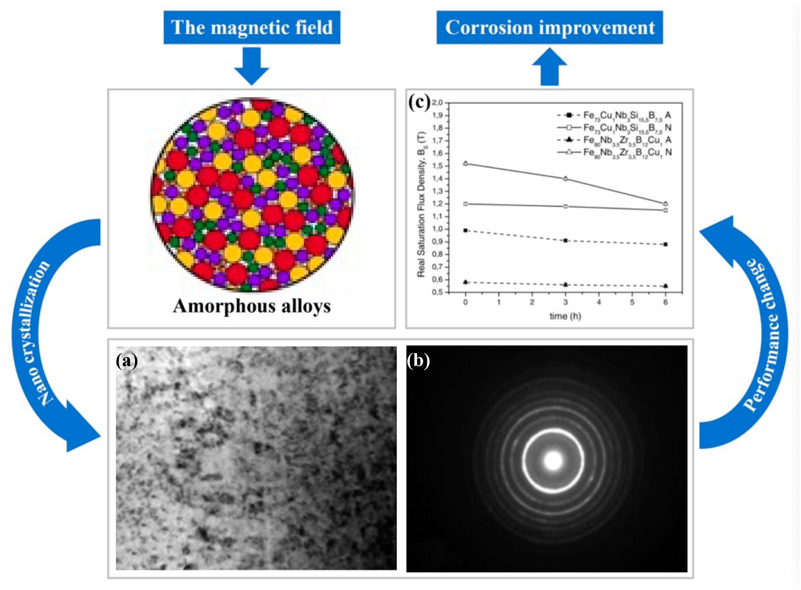
  195. Souza, C.; May, J.; Carlos, I.; de Oliveira, M.; Kuri, S.; Kiminami, C. Influence of the corrosion on the saturation magnetic density of amorphous and nanocrystalline Fe73Nb3Si15. 5B7. 5Cu1 and Fe80Zr3. 5Nb3. 5B12Cu1 alloys. J. Non-Cryst. Solids 2002, 304, 210–216. [Google Scholar] [CrossRef]
  196. Gostin, P.; Gebert, A.; Schultz, L. Comparison of the corrosion of bulk amorphous steel with conventional steel. Corros Sci. 2010, 52, 273–281. [Google Scholar] [CrossRef]
  197. Guo, R.; Zhang, C.; Chen, Q.e.; Yang, Y.; Li, N.; Liu, L. Study of structure and corrosion resistance of Fe-based amorphous coatings prepared by HVAF and HVOF. Corros Sci 2011, 53, 2351–2356. [Google Scholar] [CrossRef]
  198. Klocke, F.; Krieg, T. Coated tools for metal cutting–features and applications. CIRP Ann. 1999, 48, 515–525. [Google Scholar] [CrossRef]
  199. Brinksmeier, E.; Gläbe, R. Advances in precision machining of steel. CIRP Ann. 2001, 50, 385–388. [Google Scholar] [CrossRef]
  200. Xiao, C. Properties of nano-SiC/Ni composite coating on diamond surfaces. Surf. Eng. 2018, 34, 832–837. [Google Scholar] [CrossRef]
  201. Stock, H.-R.; Schlett, V.; Kohlscheen, J.; Mayr, P. Characterization and mechanical properties of ion-implanted diamond surfaces. Surf. Coat. Technol. 2001, 146, 425–429. [Google Scholar] [CrossRef]
  202. Lee, Y.J.; Hao, L.; Lüder, J.; Chaudhari, A.; Wang, S.; Manzhos, S.; Wang, H. Micromachining of ferrous metal with an ion implanted diamond cutting tool. Carbon 2019, 152, 598–608. [Google Scholar] [CrossRef]
  203. Prawer, S. Ion implantation of diamond and diamond films. Diamond Relat. Mater. 1995, 4, 862–872. [Google Scholar] [CrossRef]
  204. Zhang, G. Method for Extending Diamond Tool Life in Diamond Machining of Materials that Chemically React with Diamond. U.S. Patent 7198043B1, 3 April 2007. [Google Scholar]
Figure 1. (a) The short-range atomic arrangements of amorphous alloys are composed of different kinds of clusters [3]. (b) The black line identifies the short-range order characteristic of amorphous alloys. (c) The medium-range atomic arrangement of amorphous alloys is randomly distributed by several clusters, adapted with permission from Ref. [4] 2011, Elsevier. (d) The long-range atomic arrangement of amorphous alloys becomes disordered.
Processes 10 01203 g001
Figure 2. The (a) Vickers hardness and (b) tensile strength of Fe-based amorphous alloys are much higher than other materials, reprinted with permission from Ref. [7] 2000, Elsevier.
Processes 10 01203 g002
Figure 3. (a) The height image with rms roughness of ~0.3 nm and (b) phase shift image. (c) Height and phase shift profiles taken from the same region (The blue line refers to the phase shift, while the red line refers to the height), adapted with permission from Ref. [14] 2000, APS. (d) Amorphous alloys after ultrasonic vibration treatment show the appearance of soft and hard regions, adapted with permission from Ref. [15] 2005, APS. (e) XRD pattern of amorphous alloy. (f) XRD pattern of the crystalline amorphous alloy, adapted with permission from Ref. [12] 2022, Elsevier.
Processes 10 01203 g003
Figure 4. (a) Bending shear band, adapted with permission from Ref. [22] 2011, Elsevier. (b) Radial shear band. (c) Semicircular shear band, adapted with permission from Ref. [23] 2011, Elsevier. (d) The shear band of amorphous alloys starts at the stress concentration at the root of the notch and extends along the plane of maximum shear stress, adapted with permission from Ref. [24] 2017, APS.
Processes 10 01203 g004
Figure 5. (a) Schematic diagram of the structural evolution of the different states of matter obtained by liquid cooling, adapted with permission from Ref. [49] 2019, Wang et al. (b) The rapid cooling process of amorphous matter, adapted with permission from Ref. [37] 2017, APS. (c) The DSC curve of BMG, the left red line is Tg, the middle of the red lines is the supercooled liquid region, and the right red line is Tx, adapted with permission from Ref. [29] 2011, nature. (d) The critical heating rate to completely bypass crystallization on heating from the glass through the liquid is about 200 K/s. Using the millisecond heating method, which enables heating rates on the order of 106 K/s, the undercooled liquid is accessible at any temperature above the glass transition, through the melting point and beyond, where the liquid enters the equilibrium state (upper left quadrant in the diagram), adapted with permission from Ref. [50] 2005, science.
Processes 10 01203 g005
Figure 6. (a) Fracture strength of amorphous alloys, adapted with permission from Ref. [7] 2000, Elsevier. (b) Comparison of magnetization strength Bs and permeability μc of amorphous alloys with various soft magnetic materials (1 kHz) [55].
Processes 10 01203 g006
Figure 7. (a) Surface corrosion of Fe32Ni36Cr14P12B6 amorphous alloy under artificial saliva. (b) Surface corrosion of Fe67Co18B14Si1 amorphous alloy under artificial plasma, reprinted with permission from Ref. [58] 2021, Elsevier. Fe-based amorphous alloys were corroded, but the surface morphology changed little.
Processes 10 01203 g007
Figure 8. (a) The SEM image of the surface of BMG after SPDT. (b) XRD pattern of BMG before and after machining, no crystallization was shown [78]. (c) Initial crystallization near the oxide layer. (d) Region of no crystallization on the right and crystallization on the left. (e) Increasing dendritic pattern with increased crystallization. (f) Region of complete crystallization of BMG, adapted with permission from Ref. [80] 2004, Elsevier. The red mark is the crystalline region.
Processes 10 01203 g008
Figure 9. (a,b) Compared with the excellent machined surface of La-based amorphous alloy, the machined surface of Fe-based amorphous alloy performs extremely poorly, reprinted with permission from Ref. [79] 2021, Elsevier.
Processes 10 01203 g009
Figure 10. SEM micrographs of the underside of BMGs chips at different shear speeds: (a) 1.06 m/s, (b) 0.50 m/s and (c) 0.25 m/s, reprinted with permission from Ref. [82] 2011, Springer. The red mark is the degree of melting of the chip surface.
Processes 10 01203 g010
Figure 11. Compressive strength versus room temperature thermal conductivity of metallic glasses, metals, and alloys in Ashby’s material space. Conventional crystalline alloys are shaded while other amorphous alloys are in orange and red, reprinted with permission from Ref. [97] 2018, Elsevier.
Processes 10 01203 g011
Figure 12. (a) Powder cores made of Fe-TM-P-C-B-Si amorphous alloy with high efficiency and low heat generation are used in inductors for laptops, adapted with permission from Ref. [93] 2013, Taylor & Francis. (b) A two-dimensional Fe76Si9B10P5 MG microscope was made by Ou, adapted with permission from Ref. [99] 2019, iopscience. (c) (Fe0.99Mo0.01)76Si9B13 catalytic purification of wastewater, adapted with permission from Ref. [98] 2010, Elsevier. (d) Fe-based amorphous alloy wire.
Processes 10 01203 g012
Figure 13. (a) The number of nanocrystals increases as the milling speed increases, adapted with permission from Ref. [102]. 2020, Elsevier. (b) Changes in microhardness from the machined surface to the inside of the workpiece after two−dimensional cutting of Fe−Si−B by Fang et al., adapted with permission from Ref. [79]. 2021, Elsevier. (c) The surface after EDM of the Fe−based BMG. (d) The XDR pattern of the Fe−based BMG after EDM [103]. Although there are many pits on the EDM machined surface, the test shows that the Fe-based amorphous alloy does not crystallize.
Processes 10 01203 g013
Figure 14. SEM micrographs of the 60−h milled Fe80Nb10B10 metallic glass hot−pressed at (a) 703 K with 880 MPa and (b) 903 K with 640 MPa. The red mark is the crack on the surface of the material after hot pressing. (c) XRD patterns of the 60 h milled samples after hot pressing at 723 K and 903 K. α−Fe is stable at temperatures of 703 K and 903 K. (d) Hysteresis loops for the 60 h milled samples hot-pressed at 723 K and 903 K. The saturation magnetization of the samples hot pressed at 703 and 903 K are 90 and 125 Am2/kg, respectively, reprinted with permission from Ref. [106] 2017, Elsevier.
Processes 10 01203 g014
Figure 15. Chip morphologies. (a) Overview of chip morphology of sample C. (b) Enlarged morphology of the area enclosed in the red rectangle in (a). A dark arrow points to the fold line. Distance between neighboring fold lines is also marked. (c) Overview of chip morphology of sample A. (d) Enlarged morphology of the area enclosed in the red rectangle in (c). Distance between neighboring fold lines is also marked. (e) Overview of chip morphology of sample B. (f) Enlarged morphology of the area enclosed in the red rectangle in (e). Distance between neighboring fold lines is also marked. (g) Overview of chips’ morphology of sample D. (h) Enlarged morphology of the area enclosed in the red rectangle in (g). Distance between neighboring fold lines is also marked, reprinted with permission from Ref. [109] 2015, Elsevier.
Processes 10 01203 g015
Figure 16. (a) DSC curves for Fe-Al-Cr-B-Si-Nb amorphous alloy. (b) DSC curves for chips with vc = 60 m/min, f = 0.09 mm/r, ap = 0.1 mm. (c) DSC curves for chips with vc = 70 m/min, f = 0.09 mm/r, ap = 0.2 mm. (d) DSC curves for chips with vc = 80 m/min, f = 0.09 mm/r, ap = 0.3 mm DSC curve of chips [100]. There is an obvious reduction in the area of the crystallization exothermic peak.
Processes 10 01203 g016
Figure 17. The cutting regional temperature variation diagram of the workpiece during the nanometric cutting process, (ac) are cross-section views of x–z plane (the first row) and vertical views (the second row), showing the cutting regional temperature variation at cutting distances of 4, 8, and 14 nm, respectively, reprinted with permission from Ref. [48] 2014, Elsevier.
Processes 10 01203 g017
Figure 18. (a) Viscous flow on the surface of the chips produced after Fe−Si−B was cut in two dimensions [100]. (b) Pyro luminescence phenomenon during cutting of Zr-based BMG. (c,d) SEM image of the Zr−based BMG after the pyro luminescence, where severe oxidation and crystallization of the BMG can be observed [114].
Processes 10 01203 g018
Figure 19. Diffusion process of carbon atoms in cutting ferrous material, reprinted with permission from Ref. [124] 2018, Elsevier. (a) Interstitial diffusion of diamond graphitization. (b) The direction of diffusion of diamond graphitization to the workpiece.
Processes 10 01203 g019
Figure 20. (a) Tool wear diagram under normal cutting. (b) Tool wear diagram under ultrasonic elliptical vibration assistance. The red mark is the main wear amount of the cutting edge. (c) The line graph of the surface roughness under different cutting speeds in ordinary cutting and cutting with the aid of ultrasonic elliptical vibration, adapted with permission from Ref. [127] 2016, Springer. (d) The edge roughness of SPDT single crystal silicon with the aid of ultrasonic vibration. (e) The center roughness of SPDT single crystal silicon with the aid of ultrasonic vibration [130].
Processes 10 01203 g020
Figure 21. (a) STS tuning of the freeform surface. (b) 3D image of machined nanometer scaled sine wave grid on single−crystal silicon. (c) Microscope image of the machined 2D sine wave grid on single−crystal silicon. (d) SEM image of ductile−cut chips, reprinted with permission from Ref. [148] 2021, Elsevier.
Processes 10 01203 g021
Figure 22. (a) Tensile fracture stresses of Ni72P18B7Al3(A), Ni49Fe29P14B6Al2(B), and Fe76P16C4Si2Al2(C) (specimens of 0.025 mm thickness). (b) Variation of microhardness values of Fe-18Cr-4Mn-xN amorphous alloy with respect to nitrogen concentration, adapted with permission from Ref. [154] 2009, Elsevier.
Processes 10 01203 g022
Figure 23. (a) Effect of the cooling strategies on the mean surface roughness Ra after 8 min of turning. (bd) Chip morphology under cryogenic, dry, and wet turning conditions after 8 min of cutting and for a cutting speed of 80 m/min, adapted with permission from Ref. [158] 2017, Elsevier. Frequent chip entanglements occurred during dry turning. In wet cutting, long tubular chips appear, which damage the tool and workpiece. The chip morphology under cryogenic turning is better.
Processes 10 01203 g023
Figure 24. SEM analysis of tool wear under different cooling strategies: (a) dry machining. (b) CO2. (c) LN2. The built-up-edge (BUE) and chipping appear on the dry cutting tool surface. CO2-assisted machining eliminates the formation of BUE, and some sticking in the form of BUL occurs on the rake face. The tool surface under LN2-assisted machining is relatively smooth, with a small amount of BUL. (d) Average flank wear and main cutting forces at feed rate of 0.1 mm/rev. (e) Average flank wear and main cutting forces at feed rate of 0.15 mm/rev, adapted with permission from Ref. [161] 2021, Elsevier. The average flank wear and main cutting force were the lowest with LN2-assisted machining.
Processes 10 01203 g024
Figure 25. (a) 3D modeling picture of the internal cooling device of the turning tool. (b) Physical picture of the internal cooling device of the turning tool, adapted with permission from Ref. [164] 2021, Elsevier. (c) Internal transfer system of MQL [174]. (d) Layout of the CG + MQL assisted SPDT device build, adapted with permission from Ref. [163] 2017, Elsevier.
Processes 10 01203 g025
Figure 26. (a) Formation of serrated chips when no magnetic field is applied. (b) Formation of flat, long and continuous chips when a magnetic field of 0.01 T is applied. (c) Formation of flat, long and continuous chips when a magnetic field of 0.02 T is applied, reprinted with permission from Ref. [190] 2022, Elsevier.
Processes 10 01203 g026
Figure 27. (a) Modeling of the machine layout when Khalil et al. [190] use magnetic field assist. (b) Modeling of the machine layout when Yip and To use magnetic field assistance. (c) Schematic of the distribution of permanent magnet and workpiece positions when using magnetic field assist, adapted with permission from Ref. [190] 2022, Elsevier. (d) Actual machine layout when Yip and To use magnetic field assist, adapted with permission from Ref. [186] 2017, Elsevier.
Processes 10 01203 g027
Figure 28. Images of Fe52Co34Hf7B6Cu1 after pulsed magnetic field treatment with nano-crystallization of the workpiece, adapted with permission from Ref. [192] 2006, Elsevier. (a) TEM micrograph of Fe52Co34Hf7B6Cu1. (b) Distinct diffraction rings are generated. It can be determined that the samples are nano-crystallized after the pulsed magnetic field treatment. (c) The values of saturation magnetic flux density, Bs, as function of the immersion time in corrosive environment (0.1 M of H2SO4 solution) for amorphous (A) and nanocrystalline (N) samples, adapted with permission from Ref. [195] 2002, Elsevier. Corrosion enhancement was obtained for both Fe73Nb3Si15.5B7.5Cu1 and Fe73.5Cu1Nb3Si15.5B7.5 after nano-crystallization.
Processes 10 01203 g028
Figure 29. Images of the machined iron surface quality with the magnified observation using a SEM and the respective surface roughness measurements: (a) standard requirements achieved after machining 50 m, (b) after machining with an unmodified diamond tool over a distance of 350 m, and (c) after machining with a gallium irradiated diamond tool over a distance of 350 m, reprinted with permission from Ref. [202] 2019, Elsevier.
Processes 10 01203 g029
Table 1. Summary of Amorphous Research Progress.
TimeEventsReferences
1959First MG from Cal. Tech. using splat quenching (Au-Si)[29]
1966Splat cooling additional findings (MIT)[30]
1969MG formation, stability, structure (Pd-Si) (Harvard)[31]
1977MG constitutive model[32,33]
1990Multi component MG formers using Copper cast (Tohoku University)[29]
2002MG tension, compression studies[34]
2003MG research with La-Al-Cu-Ni (GFA)[35]
2004Application in MEMS, biomedical, sporting goods, and electronics[36]
2005MG corrosion wear resistance[37]
2007Drilling, machining studies on MG[38]
2008MG model into ABAQUS FEA program[36]
2012MG cold rolling studies[39]
2013MG foam reduce osteopenia in biomedical[40]
2013MG by 3D SLM started[41]
2015Honeycomb MG[42]
2016MG descriptor on GFA best element combination (AFLOW framework)[43]
2017MG using 3D SLM with crack-free, complex geometry[44]
2019MG measured in a levitation device under microgravity[45]
Table 2. BMG machining conditions [109].
Sample
ID
Feed
Rate (mm/min)
DOC
(μm)
Spindle
Rate
(r/min)
Groove Depth
(nm)
Distance
between Fold Lines (μm)
Tool
Moving Speed (μm/s)
A101200070.357
B2032000141.0816
C1032000200.268
D1035002001.7818
Table 3. Magnetic parameters and resistivity of Fe-based nanocrystalline alloys at 77 and 300 K [151].
CompositionMS (300 K)
(A m2/kg)
MS (77 K)
(A m2/kg)
HC (300 K) (A/m)HC (300 K) (A/m)
Fe73.5Si13.5Nb3B9Cu1139.5151.90.520.81
Fe68Si15.5Al3.5Nb3B9Cu1113.3127.60.351.26
Fe65.5Si16.5Al5Nb3B9Cu198.398.30.500.58
Fe63Si17.5Al6Nb3B9Cu180.480.41.120.45
Fe62Si18Al7Nb3B9Cu164.164.11.481.45
Table 4. Tool wear and chip adhesion to the cutting tools under the various cooling condition: MQL; CG; and MQL + CG, adapted with permission from Ref. [163]. 2017, Elsevier.
Cooling
Conditions
MQLCGMQL + CG
Tool wear Processes 10 01203 i001 Processes 10 01203 i002 Processes 10 01203 i003
Chip adhesion Processes 10 01203 i004 Processes 10 01203 i005 Processes 10 01203 i006
Publisher’s Note: MDPI stays neutral with regard to jurisdictional claims in published maps and institutional affiliations.

