Abstract
Compliant foil gas seal is a non-contact and high-efficiency sealing technology. The dynamic performance of compliant foil gas seal with different structure parameters was analyzed in this paper. These parameters include the seal diameter, gas film thickness and the ratio of groove. Compared with the rigid film, the advantage of compliant film is analyzed. The stability performance and dynamic performance with the different structures are obtained. The results show that the larger diameter is a disadvantage for the stability performance. However, the increase of seal length can decrease the leakage. Otherwise, the increase of gas thickness improves the dynamic characteristics with the leakage rising and gas force dramatically decreasing. While the groove length ratio is around 0.6, the seal performance and dynamic characteristics are best. The compliant structure benefits the improvement of the sealing performance.
1. Introduction
To improve the aero-turbine efficiency of turbomachinery, advanced sealing technology is regarded as one of the important technical methods. This can achieve the goal of high performance turbomachinery with lower consumption under intricate operation conditions [1,2]. As an advanced sealing technology, cylindrical gas film seal technology is one of the important research fields of fluid sealing technology. The proposal and development of cylindrical gas film seal is mainly to solve the problem of an insufficient end face gas film adaptive structure. The major direction includes geometric structure, groove structure, compliant support and orifice static ring. Tae carried out a computational fluid dynamics simulation analysis on the annular cylindrical gas film seal technology, and predicted the change of the dynamic coefficient of the annular seal [3]; Childs increased the sealing efficiency of cylindrical gas film by opening holes on the stationary ring [4]; Ma carried out numerical research on a cylindrical gas film seal. This is based on the traditional dynamic pressure structure of spiral groove, and they explored the sealing efficiency and dynamic performance of a cylindrical gas film seal [5,6,7,8]. Su studied the performance of a cylindrical gas film seal. The groove type is the bidirectional characteristics of T-groove. However, the stiffness and damping coefficient was not analyzed [9]. Lu analyzed the gas film models of a slotted groove and a spiral groove with the numerical analysis method, especially in the single groove [10,11]. Jiang analyzed the fluid–structure interaction of annular seals with transient turbulent methods. However, the effect of groove on the seal performance was ignored [4,12]. These scholars did not analyze the specific compliant structures. The main challenge is how to deal with the relationship between millimeter level compliant structures and micro gas film. This is a multi-scale analysis. The compliant foil gas seal is one of the compliant structures of cylindrical gas film seal technology. The compliant structure was proposed by Mohsen. The high temperature and turbulence performance of the compliant foil gas seal during differential pressure and structure parameters was discussed [13,14,15]. These studies show that the compliant structure has an advantage over the rigid film. This structure is based on hydrodynamic air bearing from the late 1990s. However, the research does not analyze microstructures such as surface grooves or texture.
As a non-contact radial cylindrical gas film seal technology, compliant foil gas seal can meet the technical requirements of modern high-end turbomachinery with low power consumption, low wear and high effective sealing efficiency. Its compliant foil structure can maintain the stability of system dynamic characteristics while the sealing interface is subjected to external loading and thermal deformation. At the same time, the compliant foil gas seal can decrease the influence of vibration suppression and anti-excitation on the rotor system. Moreover, it can also ensure the stability of the sealing system and improve the efficiency of turbine machinery. These can meet the performance requirements of advanced aero-turbine machinery.
Combined with the sealing characteristics of compliant foil gas seal, this paper establishes the T-groove structure model and numerically analyzes the sealing characteristics and dynamic performance under different geometric parameters. In addition, the pressure distribution of a compliant structure with the rigid structure was compared in this paper.
2. Geometric Model
The model of compliant foil gas seal is shown in Figure 1. The compliant foil gas seal is composed of seal cavity, bump foil, top foil, and rotor and shaft sleeve. While the rotor eccentrically runs, the gas film between shaft sleeve and top foil forms a dynamic pressure distribution. This can reduce gas leakage. The main difference between compliant foil seal and hydrodynamic air bearing focuses on the design of the top foil. The top foil on the high-pressure side of the compliant foil seal is formed by bending and slip foil, as shown in Figure 1b and the top foil is fixed on the sealing cavity by the clamping bolt. The deformation of the compliant foil will occur to reduce the leakage as the clearance changes due to the thermal and vibration. The structural parameters of compliant foil gas seal include seal diameter, gas film thickness and groove length ratio in this paper. The sealing parameters of compliant foil are shown in Table 1. The T groove is shown in Figure 1c.
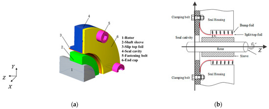
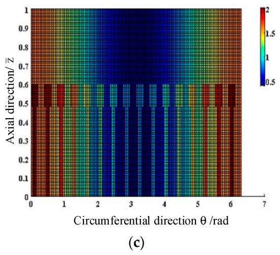
Figure 1.
The analysis model of compliant foil gas seal. (a) The three-dimensional model of compliant foil gas seal; (b) The schematic of compliant foil gas seal; (c) The T groove layout of compliant foil seal.

Table 1.
The parameters of compliant foil gas seal.
2.1. Flow Pattern
In this paper, the flow factor is used to judge the flow pattern Equation (1) [16]:
is Couette Reynolds number and is Poiseuille Reynolds number. It is turbulent as . It is laminar as . The flow factor in Equation (1) is the Reynolds number. It is affected by shear flow and differential pressure flow. This can be calculated by Equations (2) and (3):
In Equation (3), is the axial average velocity. This is determined by Equation (4). In this paper, it is deduced through the pressure flow integration under the micro gap:
The structural parameters used in this paper are variable values, so the Reynolds number and the estimated axial velocity are the maximum values. After numerical calculation, the maximum axial velocity is . The and was obtained. The value is lower than 900/1600. Therefore, the gas film–structure model belongs to the scope of the laminar flow regime in this paper.
2.2. Analysis Method
In this paper, the variation of film pressure in the Y direction is ignored because the film thickness in this direction is small and the film scale relative to axial and circumferential directions can be ignored. Therefore, transient Reynolds Equation (5) used in program analysis in this paper [17]:
In Equation (5), variables , , and represent dimensionless pressure, film thickness, axial length and circumferential angle respectively. The represents compression number. This is expressed by Equation (6):
In this paper, the finite difference method discrete Equation (5) is used to solve the sealing performance, including gas leakage, gas force, gas film stiffness and gas film damping. The changes of inertial force and temperature field are ignored in this paper. The film thickness is expressed by Equation (7):
The is the structure constant of the foil structure. It depends on the material. The material is beryllium bronze. The difference scheme of pressure is expressed by Equation (8):
The leakage and force are expressed by:
and represent the force of circumferential and axial direction.
The and of Equation (14) represent the perturbation term. The rotor dynamic coefficients include direct stiffness (Kxx, Kyy), cross coupled stiffness (Kxy, Kyx), direct damping (Cxx, Cyy) and cross coupled damping (Cxy, Cyx). Direct coefficients are important for the stability of the seal system. However, cross coupled coefficients have a negative influence on the stability of the rotor-seal system.
3. Results and Discussions
3.1. Numerical Analysis for Reliability
Figure 2 shows that the leakage changes with different film thicknesses and pressure distribution changes with the circumferential position. In Figure 2a, compared with the calculated results in reference [9,10], the leakage of this paper with the film thickness is basically consistent with the results. These results are the same order of magnitude. This verifies the correctness of the calculated leakage in this paper.
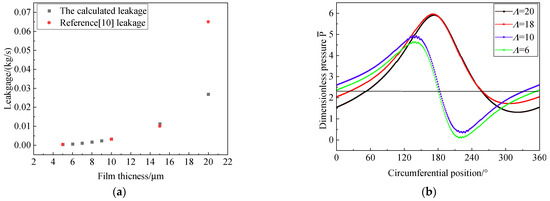
Figure 2.
The verification of calculated results. (a) Calculated leakage with Ref. [10]; (b) The pressure distribution with different Λ.
Figure 2b shows the pressure distribution along different axial positions with different . The pressure distribution is similar to the trend of the grooved structure in reference [18]. With the increase of the compression number, the position of the highest pressure moves from 140° to the center position near 180°. As the same time, the pressure peak of the gas film rises. However, the pressure wave trough gradually disappears with the increase of compression number. This is caused by the improvement of the dynamic pressure effect while the speed increases. The compression number only depends on the speed while the structure parameters and other operation conditions are ensured. This can also verify the accuracy of the calculated results in this paper.
3.2. The Pressure Distribution with Compliant Structure
In this paper, the compliant structure is analyzed. Figure 3 shows the pressure distribution of the compliant foil gas film and rigid gas film. The curve in Figure 4 represents the pressure distribution of the compliant gas film and the rigid gas film along the axial length.
Figure 3.
The effect of compliant structure on pressure distribution of the axial direction.
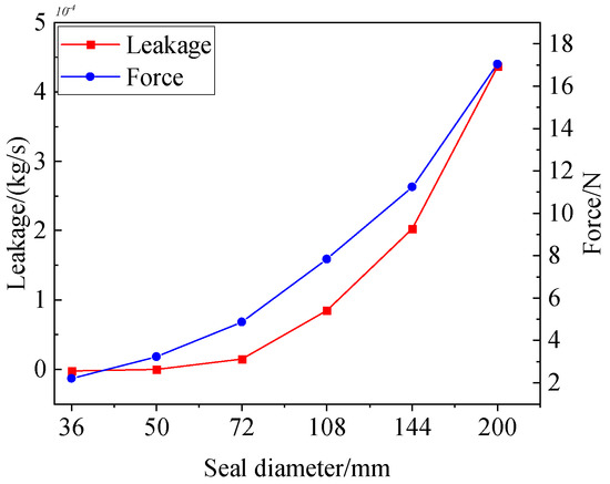
Figure 4.
The effect of seal diameter on leakage and force.
As we can see from Figure 3, the influence of compliant foil on the pressure distribution of gas film is obvious. The increase of compliant coefficient results in the increase of the pressure dynamic. This is possible to decrease the leakage of gas film and improves the seal performance of gas film. Otherwise, this is also one of the reasons for designing a compliant structure. Therefore, the influence of the compliant structure on the seal characteristics on gas film should be considered in multiscale analysis.
3.3. The Effect of Seal Diameter on Seal Performance
Considering the initial condition, the equation of leakage, gas force and rotodynamic coefficients are numerically solved in the multi-scale model. The model includes micro gas film and millimeter compliant foil.
Figure 4 shows the effect of seal diameter on steady performance. The speed is 10,000 r/min and the eccentricity is 0.5. As we can see in Figure 4, the leakage and gas force show an increasing trend as the seal diameter increases. The variation of leakage is more obvious than the gas force. It can be seen from Figure 4 that the leakage gradually increases exponentially while the seal diameter rises to 72 mm. However, the changing trend of leakage is not obvious while the seal diameter is small. This means that the seal performance is relatively good. The gas force increases gradually with the increment of seal diameter, but the magnitude of gas force varies little. The multiscale analysis shows that the effect of the seal diameter on dynamic pressure is obvious with the same speed and eccentricity. Therefore, the linear velocity of compliant gas film obviously rises with the increase of seal diameter. This results in the increase of dynamic pressure and gas force. Therefore, the seal clearance and seal width should be adjusted appropriately to ensure the seal effectiveness while the seal diameter is large.
Table 2 shows that the changes of leakage in different seal diameters and widths. It can be seen from Table 2 that the leakage is almost the same after increasing the seal width with different seal diameters. This means that the same seal diameter to seal width ratio presents almost the same dynamic pressure effect.
Table 2.
The leakage with different seal diameter and width.
Figure 5 presents the effect of seal diameter on the rotodynamic coefficients. Figure 5a shows the variation in the relationship between the gas stiffness and the seal diameter. It can be seen from Figure 5 that the direct stiffness coefficient and cross coupled stiffness increase with the raise of the seal diameter. The cross stiffness is lower than the direct stiffness. However, the increment of the cross stiffness is significantly higher than the direct stiffness. The sharp increase of the cross stiffness coefficient is negative for the stability of the compliant foil gas seal during operation. The influence of cross stiffness should be minimized during the operation of the seal system. Therefore, the increase of seal diameter is not positive for the stability of the compliant foil gas seal system as the operation conditions are same. Moreover, the direct stiffness Kxx and Kyy is symmetry about Y = 1,000,000 N/m as the seal diameter is larger than 108 mm and the cross coupled stiffness Kxy and Kyx is symmetry about Y = 0 N/m.
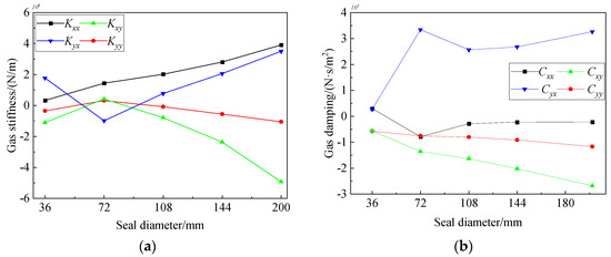
Figure 5.
The effect of seal diameter on the rotodynamic coefficients. (a) The effect of seal diameter on gas stiffness; (b) The effect of seal diameter on gas damping.
Figure 5 shows the variation in the relationship between gas damping and seal diameter. It can also be seen from Figure 5b that the direct damping and cross coupled damping increase with the increase of seal diameter. The changing trend of the direct damping with the increase of the seal diameter gradually weakens. The increasing trend is significantly lower than that of the cross damping. This increases the instability of the seal system. It is a benefit for the seal system to control the seal diameter. As we can see from Figure 5, the rotodynamic coefficients are positive for the stability of the seal system as the seal diameter is around 108 mm.
3.4. The Effect of Film Thickness on Seal Performance
Figure 6 shows the effect of film thickness on steady performance. The leakage increases dramatically with the increase of film thickness. The increase rate shows an accelerating trend. On the contrary, the gas force decreases and then gradually tends to be flat with the increase of gas film thickness. It is considered that the reason is that the increase of gas film thickness increases the seal clearance. The seal clearance makes the dynamic pressure effect and the pressure distribution decrease. This leads to a decrease of the gas force. Similarly, this causes the increase of the gas leakage.
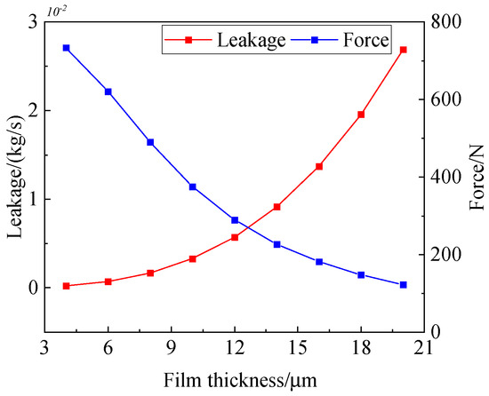
Figure 6.
The effect of gas film thickness on leakage and force.
Figure 7 presents the variation in the relationship of rotodynamic coefficients with gas film thickness, respectively. It can be seen from Figure 7 that gas film stiffness and gas film damping gradually weaken and trend to zero with the increase of gas film thickness. This is caused by the increase of leakage and the decrease of the gas force. This leads to the weakening of the dynamic pressure effect. The decrease of the pressure distribution of gas film means a lack of the conditions necessary for the increase of the dynamic characteristic coefficient. The direct stiffness Kxx and Kyy is symmetry about zero.
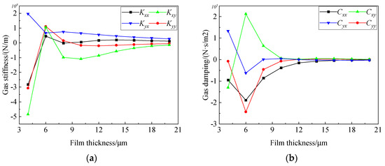
Figure 7.
The effect of film thickness on the rotodynamic coefficients. (a) The effect of film thickness on gas stiffness; (b) The effect of film thickness on gas damping.
At the same time, it can be seen from Figure 7a that the rotodynamic coefficient fluctuates greatly as the gas film thickness is relatively smaller than 10 μm. The cross coupled stiffness is significantly lower than the direct stiffness while the gas film thickness is lower than 10 μm. However, the cross coupled damping is significantly higher than the direct damping from Figure 7b. On the one hand, it may be possible that the dynamic pressure effect is intense while the gas film thickness is too small. This causes the non-uniformity pressure distribution of compliant gas film and the instability of the seal system. On the other hand, it may be possible that it results in fluid discontinuity as the gas film thickness is too small. Comprehensively, the seal performance and stability of the sealing system are best while the gas film thickness is about 10 μm.
3.5. The Effect of Groove Length Ratio on Seal Performance
Figure 8 is the effect of the groove length ratio on steady performance. It can be expressed in equation:
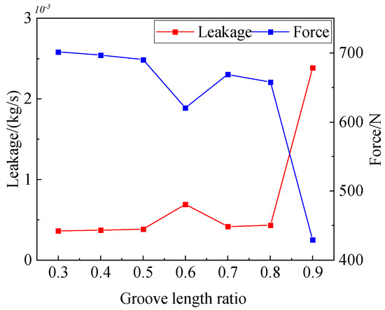
Figure 8.
The effect of groove length ratio on leakage and force.
Figure 8 shows that the leakage increases significantly while the groove length ratio is greater than 0.8. The exponential change of gas leakage occurs. Moreover, the gas force decreases sharply. These are caused by the rises of the leakage channel with the increase of groove length. The leakage channel has an influence on the differential pressure flow. The differential pressure flow has a negative effect on the dynamic pressure effect caused by the shear flow. As a result, the gas force decreases and the leakage increases.
Figure 9 shows the effect of groove length ratio on the rotodynamic coefficients. As we can see from Figure 9, the cross coupled stiffness and the cross coupled damping are lower than the direct stiffness and direct damping as the groove length ratio is lower than 0.6. This benefits the stability of the seal system.
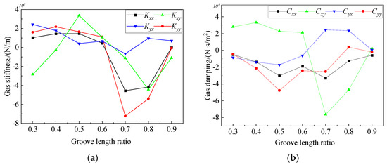
Figure 9.
The effect of groove length ratio on the rotodynamic coefficients. (a) The effect of groove length ratio on gas stiffness; (b) The effect of groove length ratio on gas damping.
4. Conclusions
In this paper, the main structure parameters of compliant foil gas seal are studied while the compliant structures are subjected to multiscale analysis, including seal diameter, gas film thickness and groove length ratio. The compliant gas film and rigid gas film are compared with the pressure distribution. The numerical results are compared with the reference. This verifies the accuracy of the multiscale analysis in this paper. The following are concluded:
- (1)
- Compared with the rigid gas film, the compliant foil improves the seal performance of the gas seal. The pressure distribution of the compliant gas film is obviously higher than that of rigid gas film. Therefore, the influence of compliant foil structure on seal performance should be considered in numerical analysis;
- (2)
- With the increase of seal diameter and gas film thickness, the leakage and cross coupled coefficients of the gas film seal dramatically increase. The cross coupled stiffness and damping are negative for the stability of the seal system. Therefore, the seal performance is improved as the seal diameter is lower than 108 mm and the gas film thickness is around 10μm. With the variation of the seal diameter and gas film thickness groove length ratio, the direct stiffness Kxx and Kyy is around the Y = 1,000,000 N/m and zero respectively;
- (3)
- Moreover, the cross stiffness and cross damping are lower than the direct coefficients as the groove length ratio is around 0.6. It benefits the stability of the seal system. The variation of the gas force is more obvious and decreases sharply. This means that the dynamic pressure effect is weakened. In sum, the multiscale analysis shows that it is positive for the stability of the seal system by choosing the compliant structure parameters.
Author Contributions
Conceptualization, X.W. and M.L.; methodology, X.W. and M.L.; software, X.W.; validation, X.W.; formal analysis, X.W.; investigation, X.W.; resources, X.W.; data curation, X.W.; writing—original draft preparation, X.W.; writing—review and editing, X.W.; visualization, X.W.; supervision, M.L.; project administration, M.L.; funding acquisition, X.W. All authors have read and agreed to the published version of the manuscript.
Funding
The current research was funded by China Scholarship Council (granted no. 201708740009); The current research has been supported by the Analysis and Testing Foundation of Kunming University of Science and Technology (granted no. 2020P20173103001).
Institutional Review Board Statement
The study was conducted in accordance with the Declaration of Helsinki, and approved by the Institutional Review Board of Faculty of Mechanical and Electrical Engineering, Kunming University of Science and Technology.
Informed Consent Statement
Informed consent was obtained from all subjects involved in the study.
Conflicts of Interest
The authors declare no conflict of interest.
Nomenclature
| L | Seal length, mm |
| ε | eccentricity |
| C | mean thickness, μm |
| N | groove number |
| ρ | density, kg/m3 |
| μ | dynamic viscosity, Pa·s |
| n | speed, rpm |
| E | modulus of elasticity, GPa |
| flow factor | |
| Couette Reynolds number | |
| Poiseuille Reynolds number | |
| differential pressure, Pa | |
| axial average velocity, m/s | |
| dimensionless pressure | |
| film thickness | |
| axial length | |
| circumferential angle | |
| compression number | |
| structure constant of foil structure | |
| Q | leakage, kg/s |
| the force of circumferential direction, N | |
| the force of axial direction, N | |
| , | the perturbation term |
| Kxx, Kyy | direct stiffness, N/m |
| Kxy, Kyx | cross coupled stiffness, N/m |
| Cxx, Cyy | direct damping, N·s/m2 |
| Cxy, Cyx | cross coupled damping, N·s/m2 |
| groove length ratio | |
| groove length |
References
- Ma, G.; Shen, X.M. Development and Analysis of Advanced Gas Film Sealing Technology. Aeronaut. Manuf. Technol. 2009, 3, 58–61. [Google Scholar]
- Wiseman, M.W.; Guo, T. An Investigation of Life Extending Control Techniques for Gas Turbine Engines. In Proceedings of the 2001 American Control Conference, Arlington, VA, USA, 25–27 June 2001. [Google Scholar]
- Ha, T.W.; Choe, B.S. Numerical prediction of rotordynamic coefficients for an annular-type plain-gas seal using 3D CFD analysis. J. Mech. Sci. Technol. 2014, 28, 505–511. [Google Scholar] [CrossRef]
- Dara, W.; Childs, J.W. Rotordynamic Coefficient and Leakage Characteristics for Hole-Pattern-Stator Annular Gas Seals—Measurements versus Predictions. Trans. ASME 2004, 126, 326–333. [Google Scholar]
- Ma, G.; Xu, G.Z.; Shen, X.M. Design and Analysis for Spiral Grooved Cylindrical Gas Seal Structural Parameter. Lubr. Eng. 2007, 32, 127–130. [Google Scholar]
- Ma, G.; He, J.; Li, X.H.; Shen, X. Numerical Calculation of Dynamic Coefficients for Gas Film Cylinder Seal. J. Mech. Eng. 2013, 49, 55–62. [Google Scholar] [CrossRef]
- Ma, G.; Li, X.H.; Shen, X.M.; Hu, G.Y. Analysis of performance and interface structure of cylinder gas film seal. J. Aerosp. Power 2011, 26, 2610–2616. [Google Scholar]
- Ma, G.; Zhao, W.; Shen, X. Analysis of Parameters and Performance for Spiral Grooved Cylindrical Gas Film Seal. Procedia Eng. 2011, 23, 115–119. [Google Scholar] [CrossRef] [Green Version]
- Su, Z.H. Numerical Simulation and Performance Analysis of Cylinder Gas Film Seal; Kunming University of Science and Technology: Kunming, China, 2016. [Google Scholar]
- Lu, J.J. Study on Dynamic Lubrication Characteristics of a New Floating Cylindrical Groove Gas Film Seal; Lanzhou University of Technology: Lanzhou, China, 2018. [Google Scholar]
- Ding, X.; He, Z.H.; Zhang, W.Z.; Lu, J.; Miao, C. Parameters analysis of steady micro-scale flow of cylindrical spiral groove dry gas seal. CIESC J. 2018, 69, 1537–1546. [Google Scholar]
- Jiang, Q.; Zhai, L.; Wang, L.; Wu, D. Fluid-Structure Interaction Analysis on Turbulent Annular Seals of Centrifugal Pumps during Transient Process. Math. Probl. Eng. 2011, 2011, 929574. [Google Scholar] [CrossRef]
- Salehi, M.; Heshmat, H. On the Fluid Flow and Thermal Analysis of a Compliant Surface Foil Bearing and Seal. Tribol. Trans. 2000, 43, 318–324. [Google Scholar] [CrossRef]
- Salehi, M.; Heshmat, H. Performance of a Complaint Foil Seal in a Small Gas Turbine Engine Simulator Employing a Hybrid Foil/Ball Bearing Support System. Tribol. Trans. 2001, 44, 458–464. [Google Scholar] [CrossRef]
- Salehi, M.; Heshmat, H.; Walton, J. High Temperature Performance Evaluation of a Compliant Foil Seal; NTRS: Huntsville, AL, USA, 2001. [Google Scholar]
- Brunetiere, N.; Tournerie, B.; Frene, J. Influence of Fluid Flow Regime on Performances of Non-Contacting Liquid Face Seals. J. Tribol. 2002, 124, 515–523. [Google Scholar] [CrossRef]
- Wang, X.L.; Liu, M.; Kao-Walter, S.; Hu, X. Numerical Evaluation of Rotordynamic Coefficients for Compliant Foil Gas Seal. Appl. Sci. 2020, 10, 382811. [Google Scholar] [CrossRef]
- Ma, G.; Zhao, W.; Shen, X.M. Three Dimensional Numerical Simulation on the Micro-gap Flow Field of Spiral Groove Gas Film Seal. Lubr. Eng. 2012, 37, 7–11. [Google Scholar]
Publisher’s Note: MDPI stays neutral with regard to jurisdictional claims in published maps and institutional affiliations. |
© 2022 by the authors. Licensee MDPI, Basel, Switzerland. This article is an open access article distributed under the terms and conditions of the Creative Commons Attribution (CC BY) license (https://creativecommons.org/licenses/by/4.0/).