Article

Development of a Mobile Robot for Mine Exploration †

1
Department of Electronic Computing Machines, South Ural State University (National Research University), 454080 Chelyabinsk, Russia
2
Department for Education in Physics and Mathematics, Nizhnevartovsk State University, 628605 Nizhnevartovsk, Russia
3
Department of Informatics and Computer Engineering, Surgut State University, 628403 Surgut, Russia
4
Nizhnevartovsk Department, Industrial University of Tyumen, 628600 Nizhnevartovsk, Russia
*
Author to whom correspondence should be addressed.
This paper is an expanded version of conference paper: “Topolsky, D.V., Topolskaya, I.G., & Plaksina, I.G. Mining explorer robot” published in 2021 International Russian Automation Conference (RusAutoCon), Sochi, Russia, 5–11 September 2021; pp. 480–485, doi:10.1109/RusAutoCon52004.2021.9537550.
Processes 2022, 10(5), 865; https://doi.org/10.3390/pr10050865
Submission received: 30 March 2022 / Revised: 15 April 2022 / Accepted: 25 April 2022 / Published: 27 April 2022
(This article belongs to the Section Energy Systems)

Abstract

:
This study focuses on aspects specific to adaptive mobile robotic systems. These include providing flexibility, high performance, the use of widely available element bases and others. The science intensity and technical level of the development of mobile robots are constantly growing. The element base of robots is constantly updated. In the presented article, the direction of research is related to the problems specific to mining robots. The use of research robots makes it possible to ensure safety of work in hard-to-reach places, monitor the status of active and idle mines, and find new minerals in idle mines, the processing of which was previously impossible. The article discusses the issues of ensuring the versatility of the design, the need to miniaturize robots, reducing the cost of the robot while maintaining high performance, achieving the required level of protection from environmental influences in mines, and compatibility with control systems. Various ways of navigating robots in a limited space are analyzed. The results of the development and testing of a mobile robot prototype are presented. When looking for ways to implement a robot, the emphasis is on an effective combination of hardware and software.

1. Introduction

Robots are increasingly capable of replacing humans in many activities. In many areas, robotics increases labor productivity, and can ensure the safety of activities. At present, we already have ready-made mass solutions for everyday life, and education, but inexpensive adaptive mobile robots for the needs of production and non-production are not yet available.
Solving the urgent tasks of automation of smart enterprises requires serious developments in the field of algorithmization of robot control processes. Along with the simplest robots prevailing today, which operate according to a strict program, robotic systems of a qualitatively different class, with adaptive capabilities and elements of artificial intelligence, should enter into widespread applicability. Adaptive mobile robots, equipped with various sensory systems and capable of easily rearranging their actions in accordance with perceived information about their working environment, are one of the most important components of flexible production systems. It is difficult to imagine the automation of the non-industrial sphere without robots. Robots are increasingly being trusted to carry out various operations in hazardous environments, under water, and in space.
The mining industry is no exception. Robotics is being introduced more and more in this industry [1,2,3]. Applications of robotics in the mining industry include robotic dozing, excavation and transport of ground, and drilling and explosives operations [4]. In addition, there are good arguments for the progress of mining robotics which include more than increasing productivity, safety and reducing costs. Currently, there is a need to meet the demand for products through access to minerals in difficult conditions [5].
Miners, geologists and rescue services often need to explore an area that is not accessible for direct inspection or analysis for various reasons:
  • Narrowness of space;
  • The likelihood of a collapse;
  • Contamination of the place.
Therefore, mining robotics is now acquiring more and more functions. The emergence of a large number of adaptive mobile robots, equipped with sensor systems and able to easily rebuild their program of action based on data received about the working environment, provides many opportunities for modernization of this technology [6]. These kinds of robots should play the role of an explorer of inaccessible places. The mining explorer robot must have good maneuverability. The main requirements for the design and functionality of such a robot include:
  • Small dimensions;
  • The best moving method;
  • Impact resistance;
  • Moisture resistance;
  • Resistance to overturning;
  • Long-term autonomy;
  • Feedback.
To date, there are already research robots [7] that have a number of similar solutions. However, not all of them meet the above requirements for a number of reasons.
  • Ground robotic complex “TurtleRover” [8].
Advantages:
  • The ability to view the area;
  • The ability to scan the area;
  • Low price (about $1400).
Disadvantages:
  • The existing geo-positioning system does not allow the determining of locations underground;
  • Communication distance through obstacles is very low;
  • Low permeability on uneven terrain.
2.
Ground robotic complex “Micro Tactical Grounds Robot (MTGR)” [9].
Advantages:
  • The ability to view the area;
  • Average control distance;
  • The ability to scan the area;
  • The ability to work as a manipulator;
  • High cross-country ability, due to four-tracked chassis.
Disadvantages:
  • The existing geo-positioning system does not allow the determining of locations underground;
  • High price (more than $5000);
  • The ability to work as a manipulator.
3.
Aircraft “Autonomous underground drone” [10].
Advantages:
  • Navigation in confined spaces;
  • The ability to scan the area.
Disadvantages:
  • Big size;
  • High probability of work failure in the case of collision with an obstacle;
  • Lack of a manipulator;
  • High price (more than $7000).
Currently, mining robots that optimally solve such a range of tasks are not represented in mass production. For this reason, finding solutions for the creating of massive universal mobile robots for mining operations is an urgent scientific task. Solving the problems of robotization of mining enterprises requires new developments in the field of algorithms for controlling robots.
The use of available hardware components and software for these purposes will further reduce the cost of mining operations. The use of the modularity principle in the design of mining robots will make it possible, through simple modifications, to adapt them for specific tasks.
The purpose of the study was to create a prototype mining explorer robot. A robot prototype has been created with widely used software and hardware. Free software was used during the development, implementation and operation phases. To ensure the navigation of the robot in a limited space, a local navigation system was used. The robot’s navigation, movement, and mapping tests were successfully completed.

2. Materials and Methods

2.1. Mining Explorer Robot Implementation Methods

Mobile robots are robots that are not tied to one physical place and are able to move in their environment [11,12]. Mobile robots can move both autonomously, without the use of navigation devices in an uncontrolled environment, or along a predetermined route, when using navigation devices in a relatively controlled space.
The main components of a mobile robot are a control device, software for the control device, sensors, a drive, and a set of actuators. The control device is usually a microcontroller, laptop or personal computer [13]. Software of mobile robots can be a low-level language, a high-level language, or special software for real-time systems. The sensors used depend on the functionality of the robot; for example, accurate calculation, tactile and non-contact sounding, triangulation, collision avoidance, positioning and other specific applications.
Vision systems are widely used as a means of perception for mobile robots [14]. This type of robot sensing system makes it possible to generate control signals for controlling the robot based on the perception and processing of video information. Currently, serial production of a wide variety of robot vision systems is expanding worldwide [15,16,17,18]. The issues of creating mobile robots are of interest to many specialists involved in the design, implementation and operation of robotic technological complexes and flexible production systems.
However, the specifics of robotic applications impose a number of requirements on the design of mobile robots, which are not only complex in themselves, but can also conflict with each other. Creating efficient mobile robots is not possible by simply combining hardware and algorithmic software developed independently of each other. When organizing such complex systems as those of mobile robots, it is necessary to take into account the combined influence of these components on the result. In particular, it should be borne in mind that high-performance computing means are not used in the design of mobile robots. Therefore, from the very beginning of the formulation of functional tasks for vision systems, one should strive to simplify them as much as possible.
Thus, to create a mobile robot, it is necessary to solve the problem of a rational choice of equipment and algorithmic support, and then coordinate these components in the robot design.
Mines are hazardous industrial environments and require regular inspections to ensure the safety of mining personnel and the smooth running of mining operations. Modern legislation requires regulatory inspections at active mines. These checks primarily ensure safe ventilation and operation. Reclamation is envisaged at the end of the life of the mines. However, the owners often ignore inspections and routine maintenance related to the restoration of mining workings. Abandoned mines are becoming more and more dangerous for personnel over time. Therefore, using a mining robot explorer to carry out an inspection in such a mine is the safest solution [5].
When inspecting a mine, a robot has to overcome a number of dangers and challenges. These include lack of ventilation, unstable ground support, water inside the mine, the creation of a mesh communication network with the control point, and the need for video transmission to determine the condition of the mine. Therefore, autonomous mobile robots are often used as inspection robots in the mining industry.
Autonomous mobile robots do not need any external guidance, such as cables, magnetic strips or sensors, to move. They can move in dynamic environments with very little external input. Autonomous mobile robots are equipped with sophisticated sensors to detect objects around them. The on-board intelligent system of such robots allows one to explore an area by loading an existing map or building one’s own map. As a result, autonomous mobile robots can operate in virtually any industrial environment. This is necessary for mines because they are inherently dynamic.
By combining a mining robot with LiDAR technology, mobile robots get the most out of their high-resolution 3D and 2D data. The sensors can provide the robot with a 360-degree real-time map so that it can navigate safely and autonomously by detecting and avoiding obstacles. LiDAR sensors are easy to install, have low power consumption, and are easily programmable with a web configuration tool [19,20].
Autonomous mobile robots are good at specialized tasks, but they cannot work outside the parameters of the environment [21]. Self-driving cars, for example, are far from ready precisely because of the complexities associated with many of the parameters that ensure safe driving. In urban conditions, it takes more than just keeping the car on a straight line. In this case, the specificity of the problem requires constant identification of all kinds of risks (cyclists, pedestrians, and other vehicles) and their prevention. The human brain is well adapted to such things and can process them without much difficulty. Nevertheless, getting robots to do this task is still very difficult. However, if the robot works in a section where people cannot venture, then its tasks are simplified [21]. Sufficient administrative and uncomplicated technical restrictions to ensure the absence of people in the dangerous area are necessary. Then, the robot does not need to worry about the possibility of causing harm to anyone. The same principle applies to the physical environment of a mine. A robot in a mine does not need to deal with high speeds, such as when driving on a highway, or tackle complex problems to identify obstacles in a forest or field. While it is difficult for a robot moving on the surface to distinguish a stone or other large obstacle in grass, it is easier for a robot working underground to distinguish between what is an obstacle and what is not. Taking into account these features of the working environment of the mine robot will reduce the financial costs of complex security systems [21]. In addition, the released computing power of the on-board computer can be used to solve other tasks.
To achieve a successful combination of various aspects of the concept under consideration in a specific robot, it is necessary to create a prototype of a mining explorer robot. The tasks to be solved include the creation of a prototype of a robot on a widespread hardware and software base, the choice of the optimal type of robot movement drive, the development of a sensing system, and the development of a communication system by the control point. A separate scientific task will be the choice of a navigation system. The solution of the above tasks will largely depend on the solution of this problem.

2.2. Robot Navigation System Methods

The design of existing navigation systems for mobile robots is based on the solution of three basic tasks:
  • Determination and bypass of various obstacles in the way of movement;
  • Making the necessary changes to the current path in the event of an emergency;
  • Ensuring the most accurate movement on a narrow path or uneven surface.
There are three main types of navigation systems [22]:
  • Global navigation systems are designed for operational navigation of ground moving objects. The use of such systems is limited to the areas of availability of satellite signal, which makes it impossible to determine a robot position inside ground and underground structures, near tall buildings and trees.
  • Personal navigation systems determine the position taking into account nearby objects. They are suitable for positioning a robot in a specific small area. They are used to define the position when the robot moves along cables, lines, or by marks.
  • Local systems use the starting point for positioning. These systems are used over relatively large known areas. Local navigation systems are used when it is necessary to control the movement of a mobile robot along a safe trajectory in confined spaces, or positioning in conditions of inaccessibility of data from external sources.
  • Navigation systems can be passive and active systems. The passive navigation system receives information about its own coordinates and other characteristics of its movement from external sources. An active navigation system is an inertial navigation system that determines positions using only its onboard sensor systems [22].
For mobile robots with a passive local navigation system, artificial beacons are required to determine their location [23]. Beacons are located at fixed points on the route, and the robot loses the ability to avoid obstacles that appear or choose an alternative path of movement. The main disadvantage of passive local systems for use in mines remains the need to maintain artificial beacons on the route. A robot with passive local navigation is able to bind its coordinates to static elements of the environment (tall tree, mountain). In this case, there is a problem with the presence of static key objects in mines when environmental conditions change (for example, the level of illumination). When working in a mine, an autonomous robot is in an environment where landmarks are very few, or they are difficult to distinguish, or are too large and cannot be used as a material point.
Thus, active local navigation systems must be used to position an autonomous robot operating in a mine. In a confined space, there are many different types of interference. Active local navigation systems use various sensors that analyze the external environment; for example, light sensors, rangefinders, and force sensors. The advantage of such systems is high accuracy, as well as being able to work in conditions of high levels of environmental interference or the absence of satellite navigation. The environment introduces imprecision and uncertainty in communication channels. The use of active local navigation systems solves navigation problems in conditions when there are problems with signal reflection, uneven lighting, and difficult terrain [24]. The most accurate solution to the navigation problem can be obtained with the help of technical vision systems, based on video cameras, laser rangefinders and other sensors. Such systems also make it possible to form a description of the area surrounding the robot, to identify potential hazards, and to find landmarks for targets [25].
For the optimal choice of the navigation system in our particular case, we will analyze the existing methods to solving such problems.

2.2.1. SLAM

Today, the most advanced technology on which robot navigation is implemented is SLAM (Simultaneous localization and mapping).
SLAM is a method of mapping in an unknown space, while monitoring current location and the distance traveled [21]. When using this method, the map is built synchronously and the robot’s position is determined. Navigation goes on the map under construction. At the heart of any SLAM method is the ability to measure the distance to objects in the surrounding space, and evaluate change in position relative to them. SLAM is used when:
  • The robot should be autonomous;
  • Nothing is known about the environment;
  • It is not possible to install beacons;
  • It is not possible to use global navigation systems indoors, underground or under water.
In SLAM, the robot builds a map step by step and determines its location on this map as it enlarges and refines. When developing an algorithm, it is necessary to define a way to describe and store an environment map in which the robot will operate. In its pure form, SLAM is limited to small areas, due to poor computational scalability of probabilistic filters. The increase in uncertainty at large distances from the map origin makes the presentation of uncertainty inaccurate. Matching data to relevant items is very difficult with high uncertainty.
Currently, most SLAM algorithms are based on three different approaches: an extended Kalman filter for SLAM, a particle filter SLAM (using the Monte Carlo method), and SLAM based on graphs (Graph-Based SLAM) [26,27].

2.2.2. Extended Kalman Filter for SLAM

This approach is based on a nonlinear Kalman filter. For a long time, the extended Kalman filter was the only method for solving the aforementioned problems. Kalman filter is a recursive filter that calculates the condition of the system k from the state k-1. Kalman’s algorithm works iteratively. At each step, the algorithm receives data from the sensors (with noise and other negative factors), and the state vector from the previous step and, using these data, estimates the condition of the system at the current step. The algorithm keeps track of the probability that the current state vector corresponds to some spread of values for each variable in the vector. In the extended Kalman filter, the state transition and observation models do not have to be linear state functions; they can be differentiable functions. The algorithm complexity is estimated as O (N3), where N is the number of landmarks relative to which a robot position in space is determined. There are methods to reduce the complexity of the algorithm to O (N2) [28].

2.2.3. FastSLAM

The FastSLAM method assumes the use of the Bayes network and particle filters. This algorithm presents one large map as a set of local maps. In this case, there is no dependence between landmarks and the time for reassessing a condition of the system is noticeably reduced [27]. Partial filters are mathematical models that represent a probability distribution as a discrete collection of particles that occupy a state space. The map is stored in the form of a connected graph, in the form of a balanced binary tree, at the vertices of which some condition is stored. The method advantage is that in this algorithm, the SLAM task is divided into (m + 1) tasks, and none of the estimates of the landmark position depend on the others. The complexity of the calculation algorithm is simplified to O (M log N), where M is the number of particles, N is the number of landmarks, relative to which a robot position in space is determined [28]. FastSLAM monitors several possible routes at the same time. FastSLAM can efficiently compute the complete follow-up SLAM. Motion updates, landmark updates, and computation of importance weights can be done in constant time for each particle. FastSLAM can be used to map over a million landmarks using the capabilities of a standard desktop computer. The disadvantages of the algorithm include a potential drop in accuracy associated with ignoring the correlation of errors in estimating the positions of landmarks [29].

2.2.4. DP-SLAM

DP-SLAM is one of the approaches to solving the problem of positioning a mobile robot using the SLAM method, which uses a relatively uncomplicated particle filter over an array of maps and positions of the robot [30]. In the DP-SLAM algorithm, the map is stored as an array, where the elements reflecting the position of obstacles have a value of 1, and all the others—0. The map is stored as a connected graph of the tree type, at the nodes of which there are particles. The computational algorithm DP-SLAM does not use landmarks, allocated in the workspace of the robot. The method disadvantage is the need to process and update significant amounts of information in memory, taking into account hundreds of sections of locally measured terrain maps. The worst-case algorithm has log-square complexity, depending on the number of particles, and linear complexity, depending on the area viewed by the laser sensor [29,31].
The SLAM task can be described as a sparse graph and links between nodes. Graph nodes are robot locations and map elements. The graph-based SLAM method has a constant refresh time of graphs and the required memory is linearly dependent on number of elements. However, the final graph optimization can be computationally expensive if the robot has traveled a long enough distance.
Thus, there are no ready-made, universal SLAM solutions for solving navigation problems. The SLAM algorithm is developed individually for the robot being used, taking into account the environmental conditions. One of the simplest and most efficient SLAM implementations is based on a particle filter. Based on these considerations, the FastSLAM algorithm was applied to control the prototype of the mining explorer robot [32].

2.3. Materials

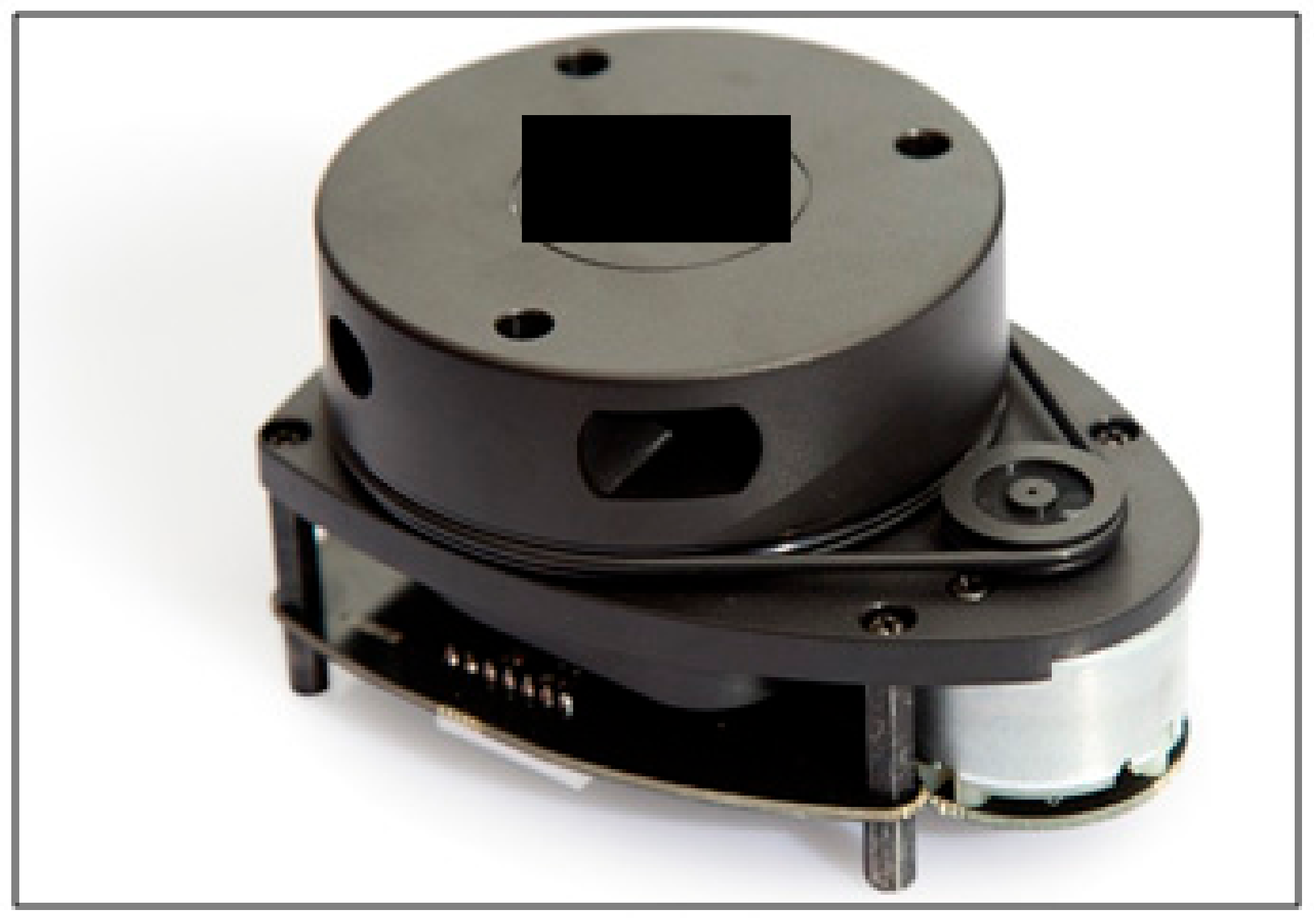
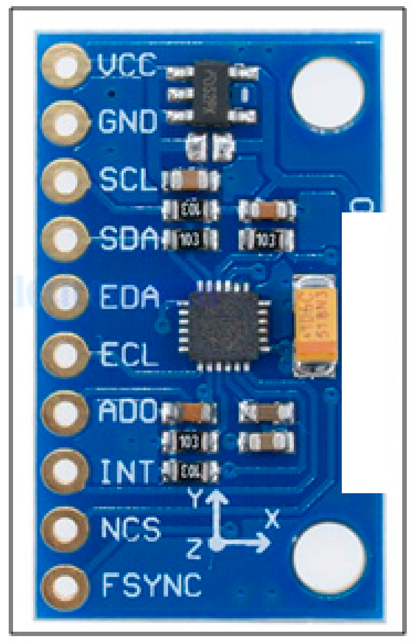
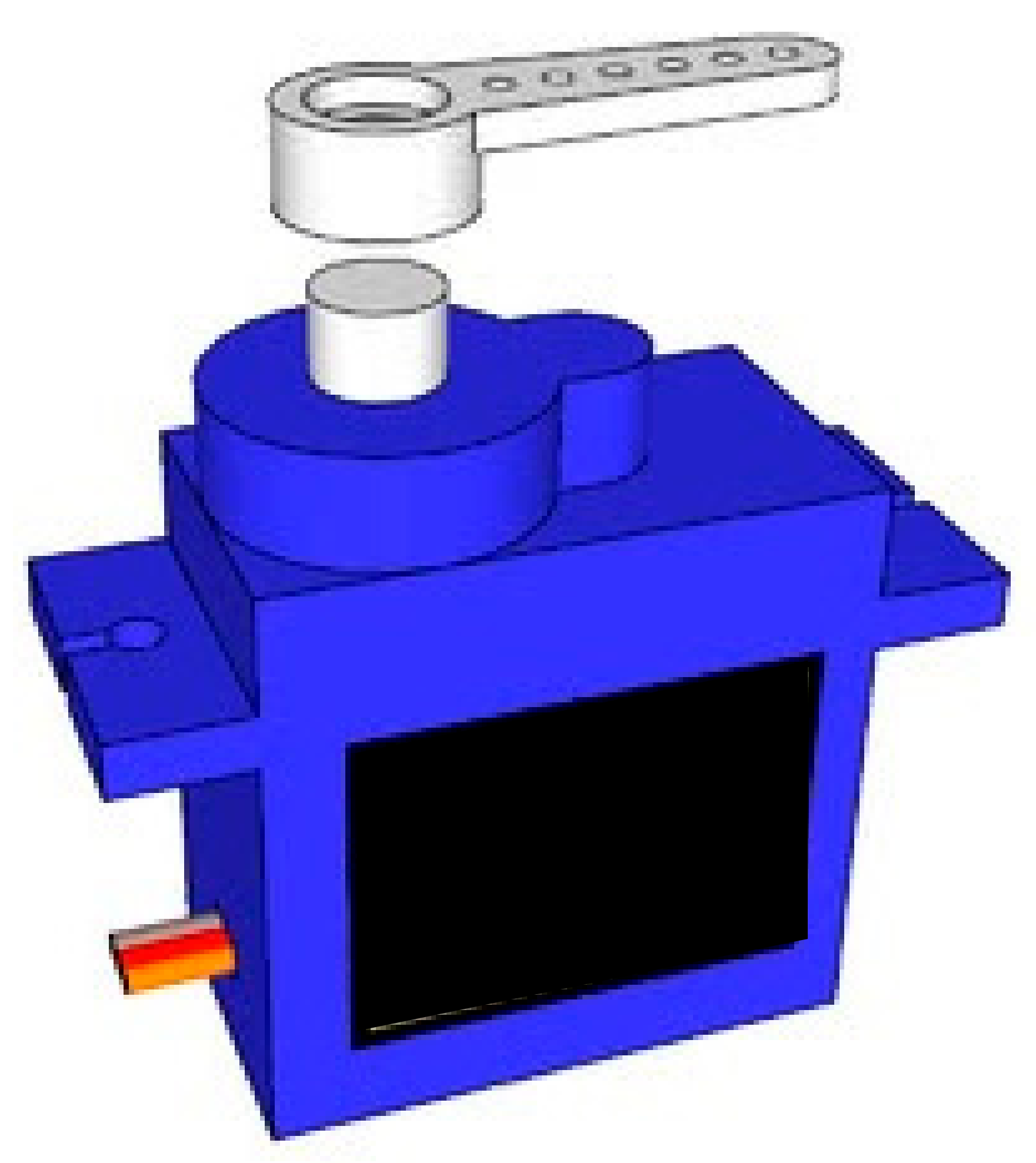
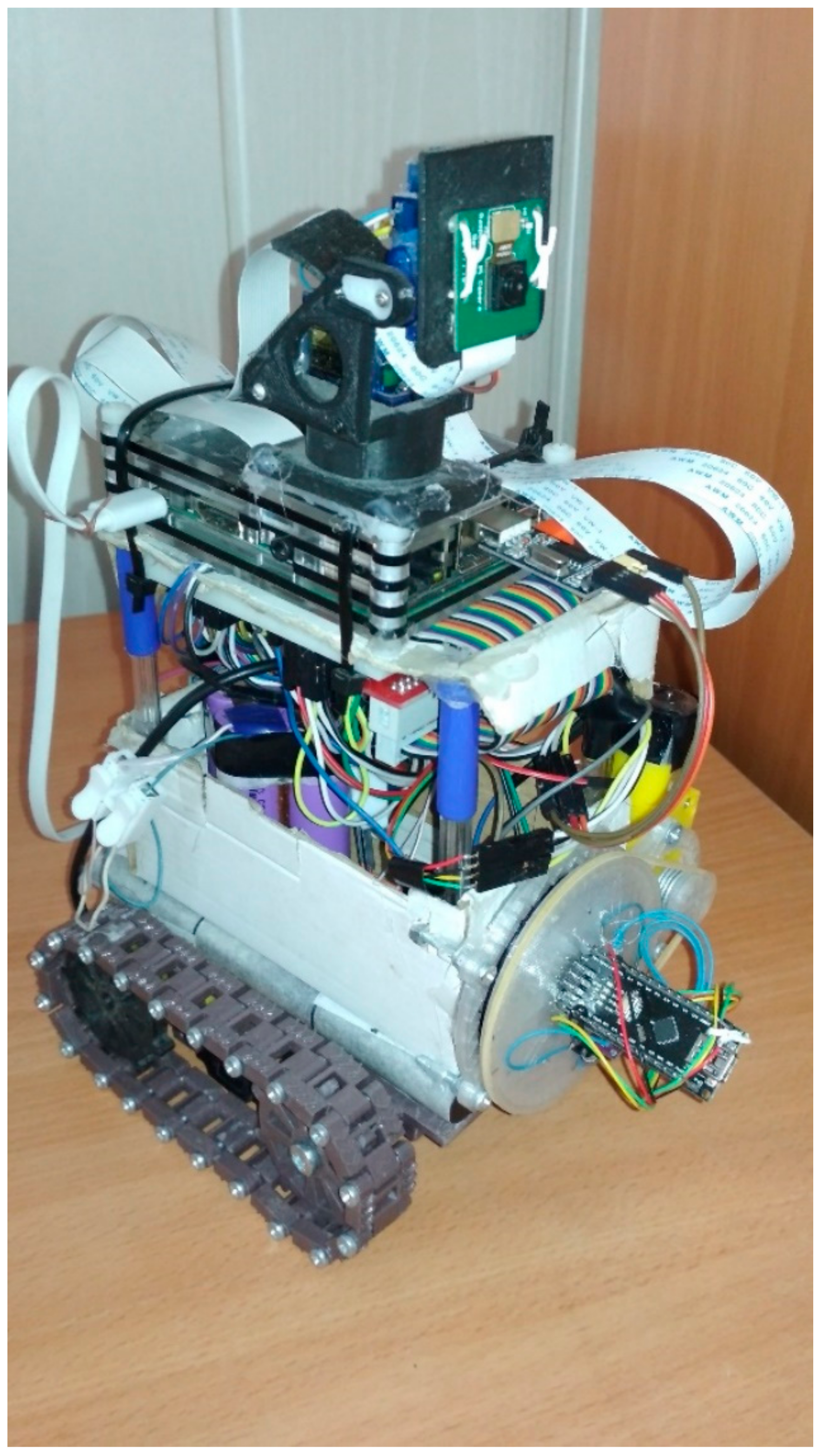
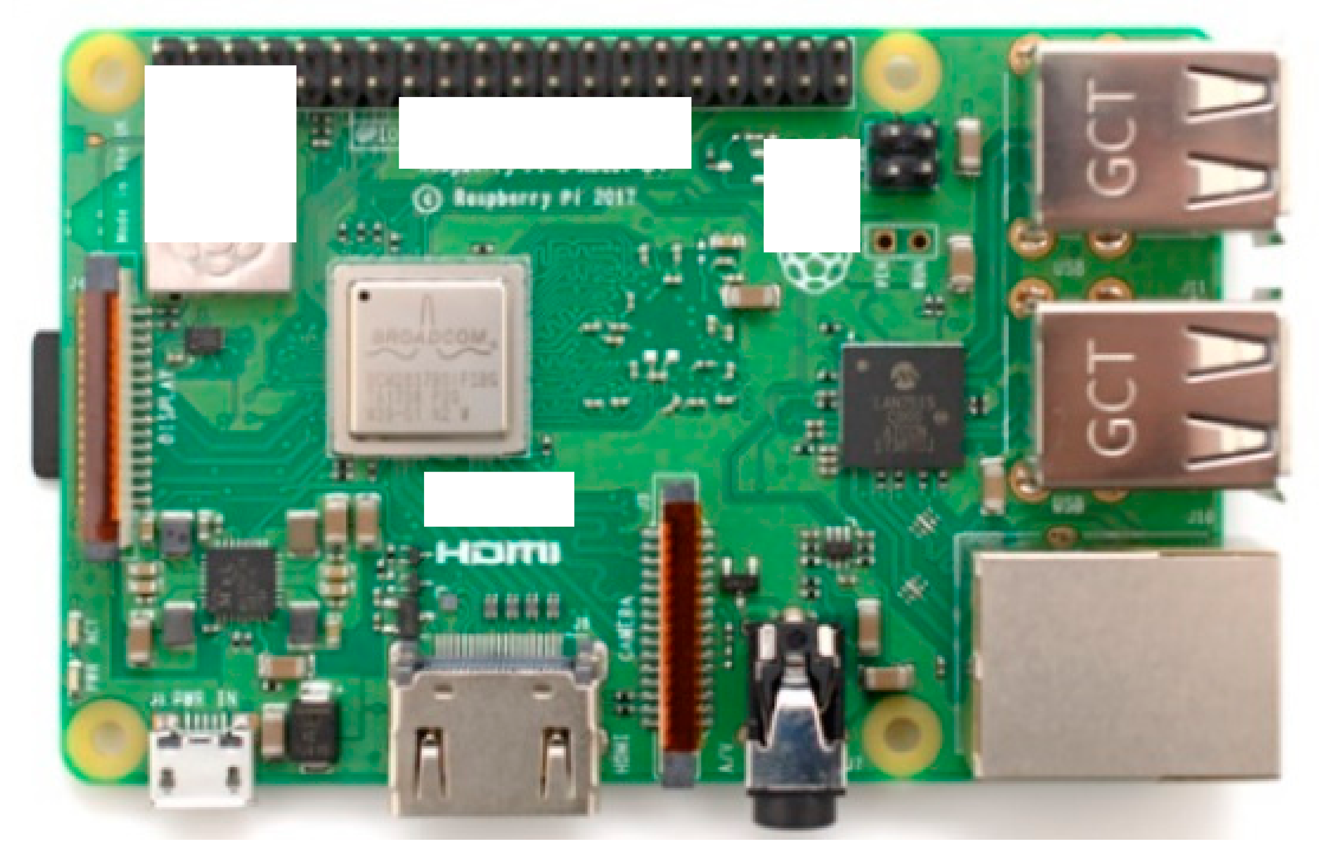
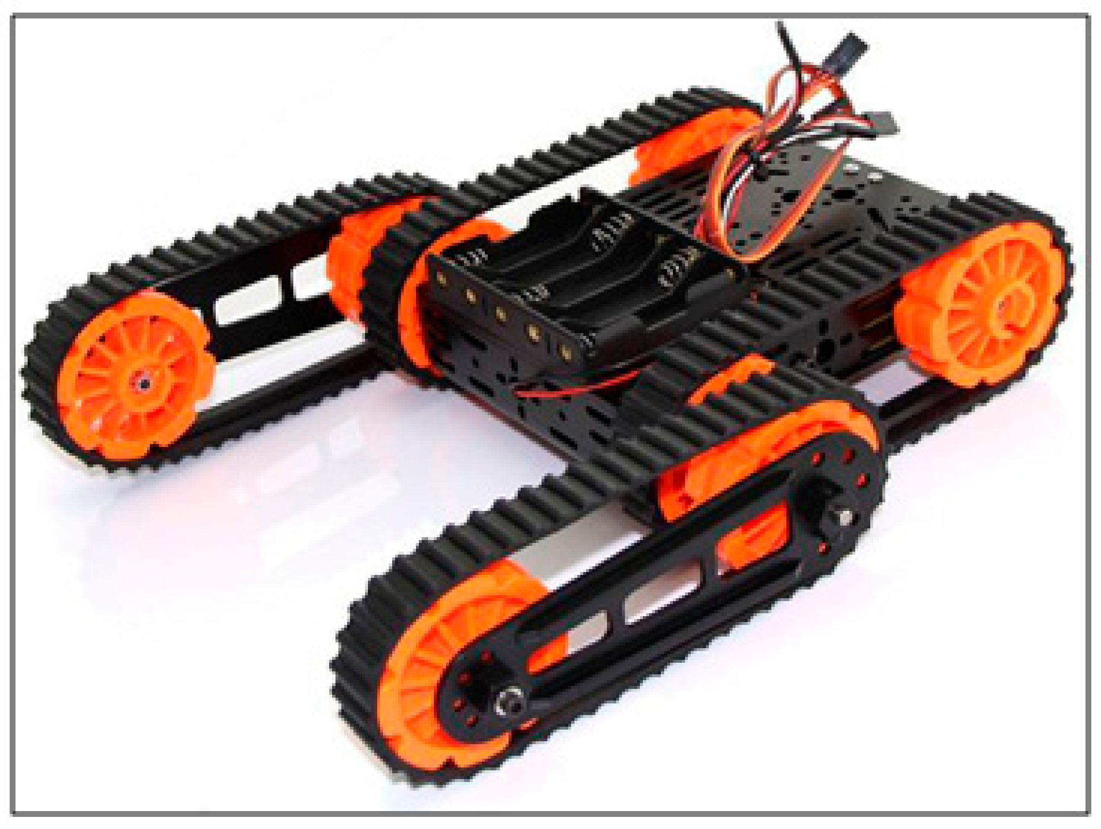
To test in action the concept of implementation and the algorithms of the developed device, it is necessary to mount a mining explorer robot prototype. The implementation was carried out from universal equipment available for mass sale [33,34]. The main components used to create the robot prototype are shown in Figure 1, Figure 2, Figure 3, Figure 4, Figure 5, Figure 6 and Figure 7, and their characteristics in Table 1, Table 2, Table 3, Table 4, Table 5, Table 6, Table 7, respectively.
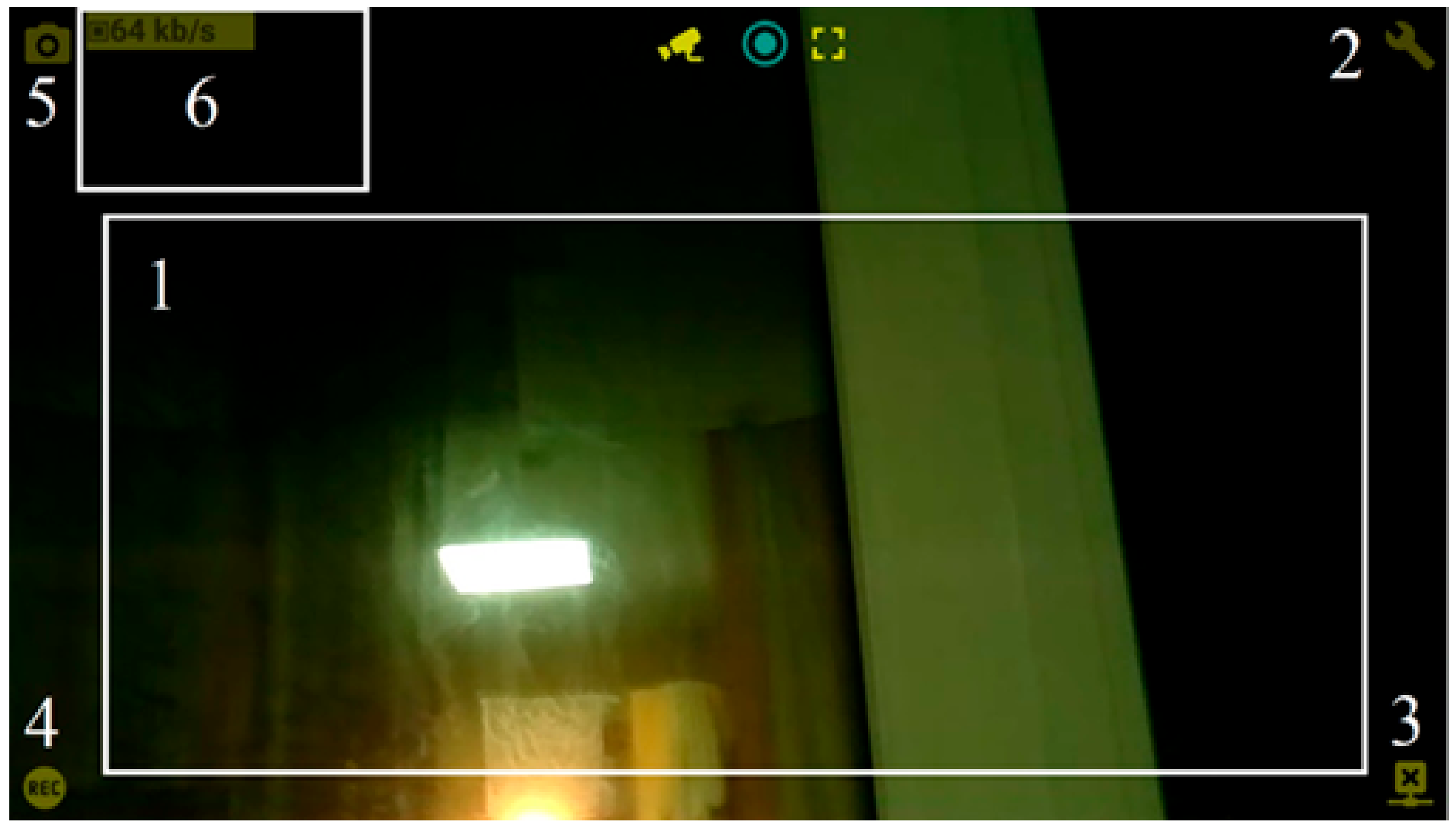
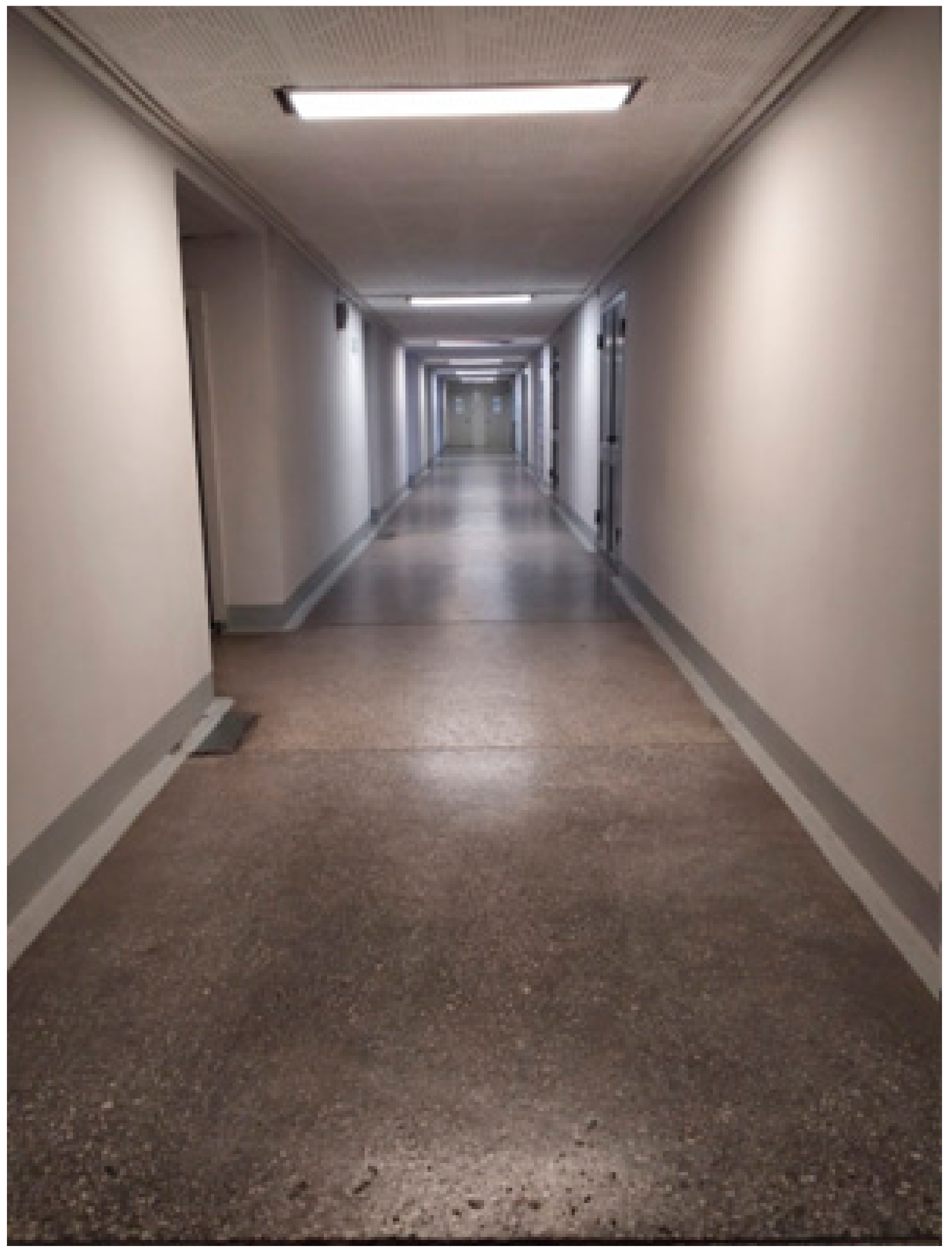
Additionally, in the construction of the prototype robot, the ultrasonic distance sensor, gas sensor, temperature, pressure and humidity sensor, and infrared sensor are used. The video image transmission from the robot’s camera was carried out on an Android smartphone.
When programming, in order to reduce the cost of the robot prototype, free software was used.
To create a mobile application, the popular, freely distributed, integrated development environment, Android Studio, was chosen. For programming a single-board computer, the Python programming language was chosen. This is because Python has many ready-made solutions for working with peripherals through general-purpose input/output ports.
The Socket interface was used to provide communication between processes as part of the study. The interface provides communication between computers using the TCP/IP protocol stack. The robot serves as the server socket, while the laptop and VR headset serve as the client socket.
When developing applications with Python, there is a need to use a GUI (graphical user interface). When creating a robot prototype, the Tkinter tool was used. Tkinter is a cross-platform GUI development library for Python. Tkinter is also free software.
For the laptop, the Linux distribution Ubuntu was chosen as the operating system. This distribution is free. Popular programming languages on Linux distributions are:
  • C;
  • C++;
  • Java;
  • Python;
  • JavaScript;
  • Shell.
For greater compatibility with the robot on the Socket interface, the Python language was chosen.
The Visualization Toolkit (VTK) was chosen as a means of displaying maps on a laptop. This open-source cross-platform library provides developers with a rich set of tools for 3D graphics, imaging and visualization. VTK supports a wide range of visualization algorithms, as well as modern computer simulation methods. The toolkit supports parallel data processing technologies, and also has extensive integration with various types of databases in software tools with a graphical interface, such as Qt and Tk.

3. Results and Discussion

To check the adequacy of results of studies the prototype robot was developed (Figure 8). This robot is equipped with a relatively powerful video camera and computer. It also has increased cross-country ability, thanks to the tracks. When developing it, the results of previous studies on the creation of mobile adaptive robots were taken into account [35,36].
The robot includes a sensor to stabilize the stereo camera and inertial navigation system, a track motion sensor, ultrasonic sensors for the robot’s response to unexpected obstacles, and a battery charge sensor. To scan enclosed spaces, the robot has two laser distance sensors arranged horizontally and vertically to scan the corresponding planes. In order to ensure the communication range of the robot with the control point during movement, signal repeaters will be used. The robot control panel is a portable personal computer. The console communicates with the robot, giving it the commands and data of the virtual reality helmet.
This prototype was created with the aim of developing a mobile system that can be remotely controlled and transmit video and data to build a 3D model of its surrounding area.
The task of ensuring the optimal way of moving the robot is solved thanks to the tracked drive, which includes the following parts:
  • Main track;
  • Auxiliary track;
  • Stepper motor as a tilt adjuster for an auxiliary track;
  • Geared motor.
  • Two pairs of tracks, so that the robot can move on very difficult surfaces.
Restrictions to the working environment of the robot are defined as:
  • Height not less than 300 mm;
  • Width not less than 300 mm;
  • The angle of the plane of movement is 45 degrees;
  • Maximum height of water obstacles 100 mm;
  • Absence of high radioactive background.
The solution to the task of ensuring communication by the control point was carried out using Wi-Fi 2.4 GHz. To increase a robot communication range with a control point, signal repeaters can be employed. These repeaters are placed on the robot in advance in a special container. In addition to the container with repeaters, the robot must be equipped with a manipulator. When the robot moves deeper into the mine, repeaters will be placed along the path of the robot.
The robot should include sensors, such as a 9-axis sensor to stabilize the camera and inertial navigation system, a track movement sensor, a battery charge sensor, and ultrasonic sensors for the robot’s response to obstacles. Two LiDARs are installed on the robot to scan confined spaces. One of the LiDARs is horizontal, the other LiDAR is vertical. Each of them scans the corresponding plane.
A laptop is used as a robot control console. For critical cases in the process of controlling the robot, one can use a virtual reality helmet. The created prototype of a mining explorer robot can operate autonomously or be controlled remotely. In the process of operation, the prototype transmits video image and data to the control point for building a 3D map of the environment (Figure 9).
Mapping tests were carried out. The robot moved in a corridor more than 30 m long, 2 m wide and 3 m high (Figure 10). The terrain scanning procedure was tested. Based on the results obtained, a model of a corridor in the form of a rectangular tunnel was built (Figure 11). No significant deviations were observed. The workspace scan test was successfully completed.
The following requirements are defined for the robot control system:
  • The ability to move forward/backward;
  • The ability to turn left/right on the spot/in motion;
  • The ability to rotate the camera at least 200 degrees horizontally, 120 degrees vertically;
  • The ability to move the manipulator, grab objects.
Based on the test results, the requirements for the robot as a whole were developed:
  • Device dimensions: no more than 300 mm (width) × 400 mm (length) × 250 (height) mm;
  • Device weight: no more than 12 kg;
  • Maximum overcome obstacle height: 200 mm;
  • Camera: at least 8 megapixels;
  • Protection from water, fire, kinetic impacts on the bottom, as well as dust, dirt;
  • Autonomy: 4 h;
  • Control range underground (3 Wi-Fi repeaters): 200 m;
  • Wi-Fi: 2.4 GHz;
  • Availability of a storage container for Wi-Fi repeaters;
  • The presence of a manipulator with a lifting capacity of at least 500 g.

4. Conclusions

The study, which has as its main result the creation of a prototype of mobile explorer robot for mines, allows us to draw a number of conclusions:
  • Market research on robots has shown that none of them is fully functional. Consequently, the creation of a robotic complex, free from the identified shortcomings, is an urgent task.
  • A prototype of the robot was created on a widespread hardware and software base. During the development, implementation and operation stages, free software was used.
  • A local navigation system is used to ensure the robot’s navigation in an enclosed space. The SLAM algorithm was developed to move the robot in the mine.
  • For the movement of the mining explorer robot, the track drive is recognized as the optimal one. Due to two pairs of tracks, the robot can move on difficult surfaces and overcome obstacles.
  • LiDARs became the basis of the robot’s visual sense. The choice of LiDARs is explained by the peculiarities of the functioning of the local navigation system.
  • A communication system with a control point was developed. The system can remotely control the robot via Wi-Fi repeaters. During the tests, the robot transmitted sensor readings, LiDAR data and a video signal.
  • Where visual sensation of mobile robots is concerned, it is not always possible to directly use methods and algorithms that are successfully used in solving problems of technical vision in other areas. This is because often a large proportion of the total computing resource must be provided for other functions of the robot.
  • Mathematical methods, algorithms and variants of software implementation should be chosen to maximize the advantages and circumvent the disadvantages of the technical means used.
  • A rational separation of functions between hardware and software methods for implementing mobile robot systems allows new models to satisfy the aggregate of stringent requirements for this type of technology. The presented prototype differs favorably in that, with high functionality, it has low cost and efficient distribution of energy consumption between the electric drive and other equipment.

Author Contributions

Conceptualization, I.T., D.T. and I.P.; data curation, D.T. and P.S.; formal analysis, D.T. and I.P.; funding acquisition, D.T., P.S., N.Y., D.F. and E.Z.; investigation, D.T. and P.S.; methodology, D.T. and I.P.; project administration, I.T. and D.T.; resources, I.T., I.P. and P.S.; software, I.T., D.T. and P.S.; supervision, D.T. and P.S.; validation, I.T. and D.T.; visualization, I.T. and D.T.; writing—original draft, I.T., D.T. and I.P.; writing—review & editing, D.T., N.Y., D.F. and E.Z. All authors have read and agreed to the published version of the manuscript.

Funding

This research received no external funding.

Data Availability Statement

Not applicable.

Acknowledgments

The team of authors is very grateful to Oleg Morozov, who made an invaluable contribution to the creation of the robot prototype and the equipment used for the experiments.

Conflicts of Interest

The authors declare no conflict of interest.

References

  1. Corke, P.; Roberts, J.; Cunningham, J.; Hainsworth, D. Mining Robotics. In Springer Handbook of Robotics; Springer: Berlin/Heidelberg, Germany, 2008. [Google Scholar] [CrossRef]
  2. Skvortsov, E.A.; Skvortsova, E.G.; Sandu, I.S.; Iovlev, G.A. Transition of Agriculture to Digital, Intellectual and Robotics Technologies. Ekon. Reg.-Econ. Reg. 2018, 14, 1014–1028. [Google Scholar] [CrossRef]
  3. Degtereva, V.A.; Ivanov, M.V.; Barabanov, A.A. Issues of building a digital economy in modern Russia. In Proceedings of the European Conference on Innovation and Entrepreneurship, ECIE, Kalamata, Greece, 19–20 September 2019. [Google Scholar]
  4. Marshall, J.A.; Bonchis, A.; Nebot, E.; Scheding, S. Robotics in Mining. In Springer Handbook of Robotics; Springer: Berlin/Heidelberg, Germany, 2016. [Google Scholar] [CrossRef] [Green Version]
  5. Chakravorty, A. Underground robots: How robotics is changing the mining industry. Eos 2019, 100. [Google Scholar] [CrossRef]
  6. Salter, T.; Michaud, F.; Dautenhahn, K.; Létourneau, D.; Caron, S. Recognizing interaction from a robot’s perspective. In Proceedings of the IEEE International Workshop on Robot and Human Interactive Communication, Nashville, TN, USA, 13–15 August 2005. [Google Scholar]
  7. Pevzner, L.D.; Kim, M.L. Robotics in Mining. 2014. Available online: https://cyberleninka.ru/article/n/robototehnika-v-gornom-dele/viewer (accessed on 30 January 2022).
  8. MTGR_Micro Tactical Ground Robot. Available online: http://robo-team.com/wp-content/uploads/2016/08/MTGR_Brochure_0121v1.pdf (accessed on 30 January 2022).
  9. LEOrover. Available online: https://www.leorover.tech (accessed on 30 January 2022).
  10. Hovermap Mining Program. Available online: https://www.emesent.io/mining-program/ (accessed on 30 January 2022).
  11. Information Engineering Main/Home Page. Available online: http://www.robots.ox.ac.uk (accessed on 30 January 2022).
  12. Moubarak, P.; Ben-Tzvi, P. Adaptive Manipulation of a Hybrid Mechanism Mobile Robot. In Proceedings of the IEEE International Symposium on Robotic and Sensors Environments (ROSE), Montreal, QC, Canada, 17–18 September 2011. [Google Scholar]
  13. Gopalakrishnan, B.; Tirunellayi, S.; Todkar, R. Design and development of an autonomous mobile smart vehicle: A mechatronics application. Mechatronics 2004, 14, 491–514. [Google Scholar] [CrossRef]
  14. Li, R.J.; Huang, Z.Y.; Kurniawan, E.; Ho, C.K. AuRoSS: An Autonomous Robotic Shelf Scanning System. In Proceedings of the IEEE/RSJ International Conference on Intelligent Robots and Systems (IROS), Hamburg, Germany, 28 September–2 October 2015; pp. 6100–6105. [Google Scholar] [CrossRef]
  15. Nocks, L. The Robot: The Life Story of a Technology; Johns Hopkins University Press: Baltimore, MD, USA, 2008; Illustrated edition (3 November 2008). [Google Scholar]
  16. Carne, N. Researchers make a million tiny robots. Cosmos Magazine, 8 March 2019. [Google Scholar]
  17. Ramos-Arreguin, J.-M. Automation and Robotics. 2008. Available online: https://www.intechopen.com/books/3607 (accessed on 30 January 2022). [CrossRef]
  18. Karel Capek—Who Did Actually Invent the Word “Robot” and What Does It Mean? Available online: http://capek.misto.cz (accessed on 30 January 2022).
  19. Evans, J.S.; Hudak, A.T. A multiscale curvature algorithm for classifying discrete return LiDAR in forested environments. IEEE Trans. Geosci. Remote Sens. 2007, 45, 1029–1038. [Google Scholar] [CrossRef]
  20. How Are Autonomous Mobile Robots Used to Inspect Mines? 2019. Available online: https://www.automate.org/blogs/how-are-autonomous-mobile-robots-used-to-inspect-mines#:~:text=A%20mining%20robot%20can%20autonomously,technologies%20need%20different%20mineral%20deposits (accessed on 30 January 2022).
  21. Hiltz, R. Taking a step into the robotic future. Mining Magazine, 22 May 2020. [Google Scholar]
  22. Bobrovsky, S.N.; Goncharov, S.N. Navigation of mobile robots. PC Week Mag. 2004, 9, 60–63. [Google Scholar]
  23. Abiyev, R.; Ibrahim, D.; Erin, B. Navigation of mobile robots in the presence of obstacles. Adv. Eng. Softw. 2010, 41, 1179–1186. [Google Scholar] [CrossRef]
  24. Karpov, V.E.; Platonova, M.V. The navigation system of mobile robot. In Proceedings of the XVIII International Scientific and Technical Conference, Warszawa, Poland, 28 September 2009. [Google Scholar]
  25. Minin, A.A. Navigation and Control of a Mobile Robot Equipped with a Laser Rangefinder. 2008. Available online: https://search.rsl.ru/ru/record/01003165917 (accessed on 30 January 2022).
  26. Montemerlo, M.; Thrun, S.; Roller, D.; Wegbreit, B. FastSLAM 2.0: An improved particle filtering algorithm for simultaneous localization and mapping that provably converges. In Proceedings of the IJCAI International Joint Conference on Artificial Intelligence, Acapulco, Mexico, 9–15 August 2003. [Google Scholar]
  27. Kuchersky, R.V.; Manko, S.V. Algorithms of local navigation and cartography for the onboard control system of an autonomous mobile robot. Tech. Sci. 2012, 3, 13–22. [Google Scholar]
  28. Sobchenko, M.I.; Ukhandeev, V.I. SLAM algorithms: Review of existing solutions. Electron. Inf. Syst. 2014, 1, 69–78. [Google Scholar]
  29. Montemerlo, M.; Thrun, S.; Koller, D.; Wegbreit, B. FastSLAM: A factored solution to the simultaneous localization and mapping problem. In Proceedings of the Eighteenth National Conference on Artificial Intelligence (Aaai-02)/Fourteenth Innovative Applications of Artificial Intelligence Conference (Iaai-02), Edmonton, AB, Canada, 28 July–1 August 2002; pp. 593–598. [Google Scholar]
  30. Eliazar, A.I.; Parr, R. DP-SLAM 2.0. In Proceedings of the IEEE International Conference on Robotics and Automation, New Orleans, LA, USA, 26 April–1 May 2004; pp. 1314–1320. [Google Scholar] [CrossRef]
  31. Eliazar, A.; Parr, R. DP-SLAM: Fast, Robust Simultaneous Localization and Mapping Without Predetermined Landmarks. IJCAI 2003, 3, 1135–1142. [Google Scholar]
  32. Pavlovsky, V.E.; Pavlovsky, V.V. SLAM technologies for mobile robots: State of the art and prospects. Robotic systems. Mechatron. Autom. Control 2016, 17, 384–394. [Google Scholar]
  33. Sensors for Robotics. Available online: https://www.chipdip.ru/ (accessed on 30 January 2022).
  34. RoboShop. Available online: https://roboshop.spb.ru/ (accessed on 30 January 2022).
  35. Plaksina, I.G.; Chistokhina, G.I.; Topolskiy, D.V. Development of a Transport Robot for Automated Warehouses. In Proceedings of the 2018 International Scientific Multi-Conference on Industrial Engineering and Modern Technologies (FarEastCon), Vladivostok, Russia, 3–4 October 2018. [Google Scholar]
  36. Topolskiy, D.V.; Topolskaya, I.G.; Plaksina, I.G. Mobile Robot for Smart Enterprise. In Proceedings of the 2019 International Multi-Conference on Industrial Engineering and Modern Technologies (FarEastCon), Vladivostok, Russia, 1–4 October 2019. [Google Scholar]
Figure 1. Single Board Computer.
Processes 10 00865 g001
Figure 2. Camera.
Figure 2. Camera.
Processes 10 00865 g002
Figure 3. Multi Camera.
Processes 10 00865 g003
Figure 4. LiDAR.
Figure 4. LiDAR.
Processes 10 00865 g004
Figure 5. Inertial Sensor.
Processes 10 00865 g005
Figure 6. Multi-track chassis.
Processes 10 00865 g006
Figure 7. Servo drive.
Processes 10 00865 g007
Figure 8. Mining explorer robot prototype.
Processes 10 00865 g008
Figure 9. Android app. Video broadcast window 1—video output field from the robot’s cameras, 2 —settings button, 3—”end connection” button, 4—“enable recording” button, 5—“frame capture” button, 6—output field for connection parameters and readings of the robot sensors.
Processes 10 00865 g009
Figure 10. Test environment.
Processes 10 00865 g010
Figure 11. Mapping tests result. Operator’s smartphone screenshot. (Colormap: blue—top, green—sides, black—bottom, white—perspective).
Processes 10 00865 g011
Table 1. Specifications of Single Board Computer.
SpecificationDescription
Dimensions85 mm × 56 mm × 17 mm
Processor64-bit quad-core ARM Cortex-A53 with a clock frequency of 1.4 GHz on a single-chip Broadcom BCM2837 chip
Random Access Memory1 Gb LPDDR2 SDRAM
USB portsUSB 2.0 × 4
Wireless networkWiFi 2, 4/5 GHz, 802.11 n
Camcorder connectorMIPI Camera Serial Interface (CSI-2)
Input/Output ports40
Table 2. Specifications of Camera.
SpecificationDescription
CCD matrix size¼ inch
Diaphragm2.35 F
Line-of-sight160-degree diagonal angle, 120-degree horizontal angle
SensorSony IMX219 (8 Mpx)
Table 3. Specifications of Multi Camera.
SpecificationDescription
Number of possible camera placementsup to 4 pcs.
Supported modules5 MP and 8 MP cameras
Table 4. Specifications of LiDAR.
SpecificationDescription
Range12 m
Angular range360 degrees
Measurement speed8000 times/s
Angular resolutionless than 1 degree
Power supply5 Volt
Table 5. Specifications of Inertial Sensor.
SpecificationDescription
Dimensions25 mm × 16 mm × 3 mm
Accelerometer measuring range±2 G, ±4 G, ±8 G, ±16 G
Gyro measurement range±250, ±500, ±1000, ±2000°/s
Gyro sensitivity131, 65.5, 32.8, 16.4 LSB/°/s
Measuring range of magnetometer compass±4800 µT
InterfaceI2C (400 kHz)/SPI (1 MHz)
Power supply3–5 Volts
Table 6. Specifications of Multi-track chassis.
SpecificationDescription
Dimensions262 mm × 222 mm × 60 mm
Power supply6–9 Volts
Maximum loadOn the move: 7.5 kg (on the ground, test with 7.4 V 1100 mAh 10 C 8.14 Wh Li-ion battery) Not moving: 50 kg (on stable support)
Table 7. Specifications of Servo drive.
SpecificationDescription
Dimensions22 mm × 11.5 mm × 22.5 mm
Power supply3–7.2 Volts
Publisher’s Note: MDPI stays neutral with regard to jurisdictional claims in published maps and institutional affiliations.

