Article

Linear Golden Section Speed Adaptive Control of Permanent Magnet Synchronous Motor Based on Model Design

1
School of Electrical and Electronic Engineering, Shanghai Institute of Technology, Shanghai 201418, China
2
Shanghai Academy of Spaceflight Technology, Shanghai 201109, China
*
Author to whom correspondence should be addressed.
Processes 2022, 10(5), 1010; https://doi.org/10.3390/pr10051010
Submission received: 10 April 2022 / Revised: 13 May 2022 / Accepted: 15 May 2022 / Published: 19 May 2022

Abstract

:
Permanent magnet synchronous motor (PMSM) is a multi-variable, strongly coupled, nonlinear complex system. It is usually difficult to establish an accurate mathematical model, and the introduction of new complex algorithms will increase the difficulty of embedded code development. In order to solve this problem, we establish the characteristic model of permanent magnet synchronous motor in this paper, and the speed control scheme of the linear golden-section adaptive control and integral compensation, which is adopted. Finally, using the model-based design (MBD) method, how to build the simulink embedded code automatic generation model is introduced in detail, and then we complete the PMSM speed control physical verification experiment. Simulation and experimental results show that compared with traditional proportional-integral-derivative (PID) control, the speed control accuracy of PMSM is improved about 3.8 times. Meanwhile, the development method based on the model design can increase the PMSM control system physical verification, and then improve the development efficiency.

1. Introduction

Permanent magnet synchronous motor (PMSM) has been widely used in automotive, aerospace, and other fields in recent years due to its small size, light weight, and high power density [1]. Because PMSM is a nonlinear, multi-variable, strongly coupled system, coupled with factors such as the parameter changes during operation, it is difficult to establish an accurate mathematical model. Therefore, in recent years the control of PMSM has also become a hot research topic.
Direct torque control (DTC) and field-oriented control (FOC) are the most common basic methods at present for PMSM. The vector control system adopts traditional proportional-integral (PI) control, which has a simple model and is easy to implement. Currently, it is widely used in PMSM. However, traditional PI control cannot solve the contradiction between overshoot and rapidity, and it is easily affected by parameter changes [2,3]. In response to this problem, based on the vector control, there are a series of modern control methods of PMSM. For example, the sliding-model variable structure control using the sliding mode control is insensitive to parameters and has a fast response speed. These two advantages improve the dynamic characteristics of the PMSM [4,5] but the control accuracy is not too high due to the existence of chattering interval. Compared with the traditional PI control, the proportional resonance control eliminates the coupling between the d and q axis components, and the system implementation is more simple [6], but it still cannot solve the contradiction between overshoot and rapidity. Fuzzy control does not require an accurate mathematical model and has strong robustness [7,8], but it relies more on control experience and expert knowledge. Although model predictive control and active disturbance rejection control can improve the speed control accuracy and dynamic performance of the system [9,10,11,12], the algorithms are complex and not easy to implement quickly. In [13], a backstepping sliding mode control based on a recurrent radial basis function network (RBFN) for a PMSM is presented, with a novel combination of the backstepping method and sliding mode control, eliminating the chattering effectively without losing the precision. In [14], an online PID parameter adjustment control, combining model predictive control and on-line fuzzy rule adjustment, is proposed. DTC is another common control method for PMSM, but it has its drawbacks with the problem of large torque pulsation particularly evident. In [15], a new DB-DTFC algorithm to solve the stator reference voltage in a stator-flux-oriented coordinate system is proposed. In [16], an analytical motor model taking the spatial harmonics and magnetic saturation characteristics of PMSM into account by reconstructing the numerical solution of magnetic co-energy (MCE) from finite element analysis (FEA) is proposed. In [17], a hybrid decision control strategy based on DNN and DTC (direct torque control) is proposed. In [18], an Ant Colony Optimization (ACO) algorithm was proposed to adjust the PID controller gains of the DTC control.
In the application of the characteristic model for PMSM, Literature [19] used the golden-section of permanent magnet synchronous motor and maintained tracking control of the integrated control method, but this paper did not consider the characteristic model and the sensitivity of the golden-section control of the step signal problems, in the initial stage. The result is that the initial stage has a larger amount of overshoot, and it is not conducive to the stability of the system. Literature [20] used the nonlinear golden-section method, and the introduction of the initial phase transition process gives the system obvious improvement, but it does not spell out the coefficient values of the transition process and the specific influence on the system, and using the nonlinear golden control method also increases the complexity of the system. It is not conducive to the realization of the ascension of the response speed and the actual system.
Based on these studies, this paper starts from the perspective of control accuracy and engineering application. Firstly, characteristic modeling of the PMSM speed control system is carried out, and then the parameters of the characteristic model are identified online by the gradient method. Only linear golden-section controller and integral controller are used to achieve stable tracking. The first-order inertial filter is introduced in the linear golden-section controller as the starting method, and the influence of the filter coefficient on the system is discussed. Finally, the paper introduces the model-based design method in the controller, gives a detailed modeling method, and uses the DSP controller and servo driver to carry out a physical verification test. Experimental results show that the method used in this paper has a high control accuracy, and based on the model design method, can greatly shorten the system verification development cycle, and can be applied to industrial control.
The main contributions to the paper are as follows:
  • Based on the characteristic model theory, the rotational speed control characteristic model of PMSM is built.
  • Based on the characteristic model theory, a linear golden section and integral compensation PMSM rotational speed adaptive model is built.
  • Based on the model design method, the specific modeling method and the verification process of the controller proposed in this paper are proposed.
  • The simulation and experiment results show that the proposed method has good performance and is suitable for practical applications.
This paper is organized as follows. In Section 1, the introduction of the control method of PMSM is given. In Section 2, the establishment process of the mathematical model and characteristic model of the PMSM is described. In Section 3, the design of the speed adaptive controller is described. In Section 4, the method of model-based design is described. In Section 5, the simulation and experimental results are given. In Section 6, the detailed conclusions and suggestions for further work are given.

2. Modeling of PMSM

2.1. Mathematical Model of PMSM

Considering the complex relationship between different variables and the complex motion law of permanent magnet synchronous motor, its dynamic mathematical model is nonlinear and multivariate. Therefore, when considering the mathematical model of the three-phase permanent magnet synchronous motor, the following conditions are assumed.
  • Ignore magnetic saturation and hysteresis loss, etc.;
  • Assuming the rotor adopts no damping winding, the external conditions change, and the physical properties of the stator do not change;
  • The conductivity of the rotor permanent magnets and the internal rotor permeability are assumed to be 0;
  • It is assumed that the induced potential in the three-phase winding is a standard sine wave during steady-state operation;
  • Ignore all spatial harmonics in the magnetic field;
  • The windings are distributed symmetrically, the windings turn’s number is the same, and the displacement electrical angles between the axes are the same.
Based on the above conditions, the stator flux Equation of permanent magnet synchronous motor in the two-phase rotating coordinate system is molded as:
{ ψ d = L d i d + ψ f ψ q = L q i q
The voltage Equation is molded as:
{ u d = R s i d + L d d i d d t ω ψ q u q = R s i q + L q d i q d t + ω ψ d
where, ψ , i and u represent flux linkage, current, and voltage respectively, ψ f is permanent magnet flux, R s is stator phase resistance, L d and L q are synchronous inductors of axis d and q respectively, and ω is angular velocity.
When the motor is running stably, assuming that the steady-state voltage and current of d-axis and q-axis are respectively, and ignore the resistance voltage’s drop, the torque Equation in the dq-reference frame is:
τ em = 1.5 p n [ ψ f i q + ( L d L q ) i d i q ]
The Equation of motion is:
τ em = τ L + 1 p n B ω + 1 p n J d ω d t
where, J is the moment of inertia, ω is the angular velocity, τ em is the electromagnetic torque, τ L is the load torque, p n is the polar logarithm, B and is the viscous friction coefficient.
In the vector control system, the more application is i d = 0 , at this point, the stator current vector on direct axis component to 0, all the current is used for torque control. The rotor magnetic field space vector is perpendicular to the magnetomotive stator force space vector, the electromagnetic torque and the current stator form a first-order linear function relationship, the counter electromotive force, and the same direction, the motor is to achieve the highest efficiency. The size of torque can be controlled through control. In this paper, surface mount PMSM is taken as the control object. For surface mount PMSM, define L q = L d = L the mathematical model under i d = 0 control mode is approximately as follows:
{ d i q d t = R s L i q p n ω i d p n ψ f J ω 1 L u q d ω d t = 3 p n ψ f 2 J i q B ω J τ L J
According to Equation (5), the speed loop of the surface mount PMSM vector control system has a linear relationship between the output speed and the q-axis current, the motor speed can be controlled by control i q . Figure 1 shows a schematic diagram of the FOC vector control system.

2.2. Characteristic Model of PMSM

According to Equation (5), PMSM can be seen as a time-varying linear time-invariant system, let
d ω d t ω ( k + 1 ) ω ( k ) T
This is,
ω ( k + 1 ) + ( B J 1 ) ω ( k ) = 3 T p n ψ f 2 J i q ( k ) T τ L J + Δ k
In Equation (7), T is the sampling period, Δ k is the discretization error. According to the characteristic model theory, for a linear time-invariant system, under a certain sampling period, the characteristic model can be described by a second-order time-varying difference Equation for position holding or tracking control [21] as Equation (8):
y ( k + 1 ) = f 1 ( k ) y ( k ) + f 2 ( k ) y ( k 1 ) + g 0 ( k ) u ( k ) + g 1 ( k ) u ( k 1 )
where, f 1 ( k ) , f 2 ( k ) , g 0 ( k ) and g 1 ( k ) are the system parameters to be identified, y ( k + n ) is the output of the system, and u ( k + n ) is the input of the system. For the convenience of control, the g 1 ( k ) u ( k 1 ) term is discarded within the allowable error range, we can get the characteristic model of PMSM by Equation (8) as Equation (9):
ω ( k ) = f 1 ( k ) ω ( k 1 ) + f 2 ( k ) ω ( k 2 ) + g 0 ( k ) i q ( k 1 )
In Equation (9), f 1 ( k ) , f 2 ( k ) and g 0 ( k ) are the system parameters to be identified, ω ( k ) is the speed output value of the system at the moment of k, ω ( k n ) are the speed output value of the system at the moment of kn and i q ( k n ) are the shaft current feedback value of the system at the moment of kn.
When the sampling time is small enough, the range of characteristic parameters is f 1 ( k ) ( 1 , 2 ] , f 2 ( k ) [ 1 , 0 ) g 0 ( k ) 1 for Equation (9), online identification of characteristic parameters can be carried out according to the input and output values. In this paper, the gradient method is adopted for identification.
ϕ ( k ) = [ ω ( k ) ω ( k 1 ) ω ( k 2 ) ] T θ ( k ) = [ f 1 ( k ) f 2 ( k ) g 0 ( k ) ] T
Then the identification Equation is [22]:
θ ( k ) = θ ( k 1 ) + λ 1 ϕ ( k ) ϕ T ( k ) ϕ ( k ) + λ 2 × [ ω ( k ) ϕ T ( k ) θ ( k 1 ) ]
where, λ 1 and λ 2 is determined by the amount of interference and the speed of convergence. In general, 0 < λ 1 < 1   0 < λ 2 < 4 .

3. Speed Adaptive Control Scheme

Based on the characteristic model, the first by the gradient method parameter online identification characteristics, and then on the basis of the theory of the all-coefficient adaptive into linear golden-section controller, to guarantee the stability of the output can track the reference signal, the integral compensation controller, among them, the reference signal using first-order low-pass filter processing. Meanwhile, the total output is limited to prevent output saturation [23]. Figure 2 shows the overall speed adaptive control system structure [24].

3.1. Input Signal Processing

For step-type speed signal, due to the large initial error, the output adjustment will be too large, which will cause system oscillation and overshoot, and will also lead to motor torque oscillation, which is not conducive to the stable operation of the motor and will cause adverse effects on the life of the motor. In order to reduce overshoot and oscillation, a first-order low-pass filter is introduced to smooth the step signal of the reference input. The discretized first-order low-pass filtering Equation is:
ω ro ( k ) = α ω ri ( k ) + ( 1 α ) ω ro ( k 1 )
where, α is the filtering coefficient, ω ro ( k ) is the filtered output value at the moment of k, ω ro ( k 1 ) is the filtered output value at the moment of k−1, and ω ri ( k ) is the input sampling value at the moment of k.
The first-order low-pass filtering method uses this sampling value and the last filtering output value to be weighted to obtain an effective filtering value so that the output has a feedback effect on the input. Among them, the smaller the filtering coefficient, the smoother the filtering result, but the sensitivity will be reduced; the larger the filtering coefficient, the higher the sensitivity, but the filtering result will be unstable.

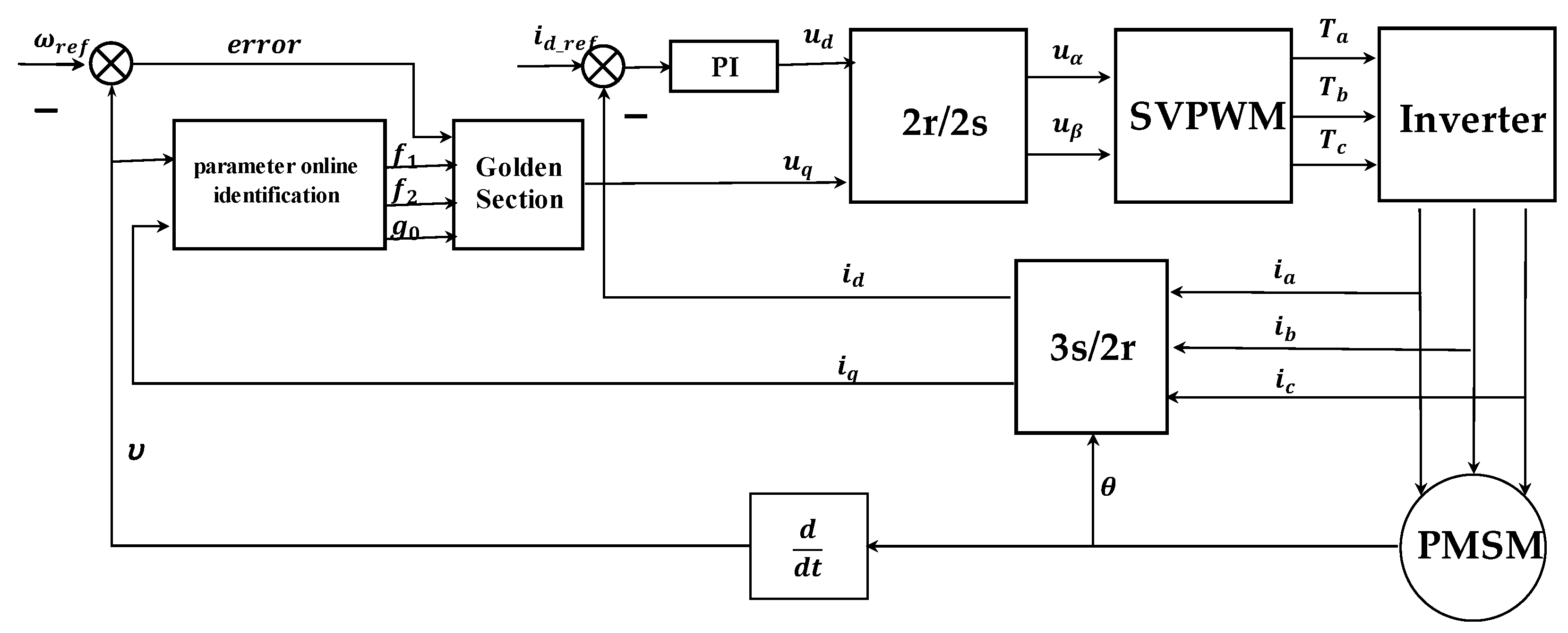
3.2. Linear Golden-Section Speed Adaptive Controller

Introducing the golden-section ratio into the control system constitutes the golden-section control. In the characteristic model adaptive control theory, the identification parameters are combined with the golden ratio, and the model parameters of the system are identified online by observing the input and output data. According to Formula (9), a linear golden-section adaptive controller of the PMSM speed control system can be designed, and the formula is:
U L ( k ) = l 1 f ^ 1 ( k ) e ( k ) l 2 f ^ 2 ( k ) e ( k 1 ) g ^ 0 ( k ) + k L
In Equation (13), l 1 = 0.382 , l 2 = 0.618 is the golden-section coefficient, and f ^ 1 ( k ) , f ^ 2 ( k ) , g ^ 0 ( k ) are the characteristic model coefficients identified online, e ( k ) is the speed error at time k, e ( k 1 ) is the speed error at time k−1, k L is the adjustable parameter, which determines the stability and immunity of the system, and 0 k L < 1 .
Based on Equation (13), the voltage control quantity of an axis q can be obtained, and a relatively stable speed control system can be achieved through adjustment k L . However, the system cannot reach the expected tracking value at this time. There is a certain steady-state error, therefore, a compensator needs to be introduced.

3.3. Integral Compensator

The characteristic model and golden-section adaptive control system have a simple structure and are easy to realize. Integral compensation also has the same characteristics and is widely used. Therefore, this paper uses integral compensator as the voltage control quantity of the second q-axis [25,26], denoted as the compensation Equation:
U I ( k ) = U I ( k 1 ) + k I e ( k )
In Equation (14), U I ( k ) is integral compensation output value the time of k, U I ( k 1 ) is integral compensation output value the time of k−1, k I is the integral coefficient, and, the total axis voltage control quantity is:
U q ( k ) = U L ( k ) + U I ( k )
The whole control system has only two adjustable parameters, and the adjustment range is determined, the overall structure is simple, and easy to achieve engineering.

4. PMSM Control System Based on Model Design

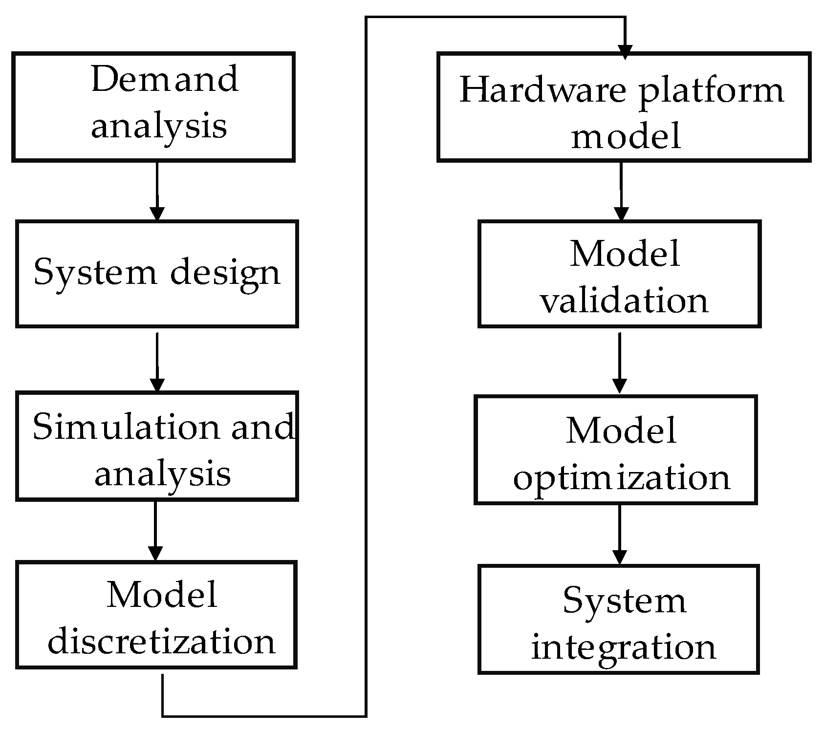
4.1. General Process of Model-Based Design

The traditional design is divided into four stages: requirement, design, implementation, and testing [27,28]. It has the disadvantages of low efficiency, high difficulty, and high requirements, which is not conducive to verifying new algorithms. Therefore, model-based design is introduced in this paper.
Compared with traditional design, model-based design connects the four stages and synchronously promotes modeling and verification testing on a unified test platform, which can reduce the migration process and enable engineers to focus on the research of algorithms, greatly shorten the development cycle and reduce the development cost. The general flow of model-based design is shown in Figure 3:

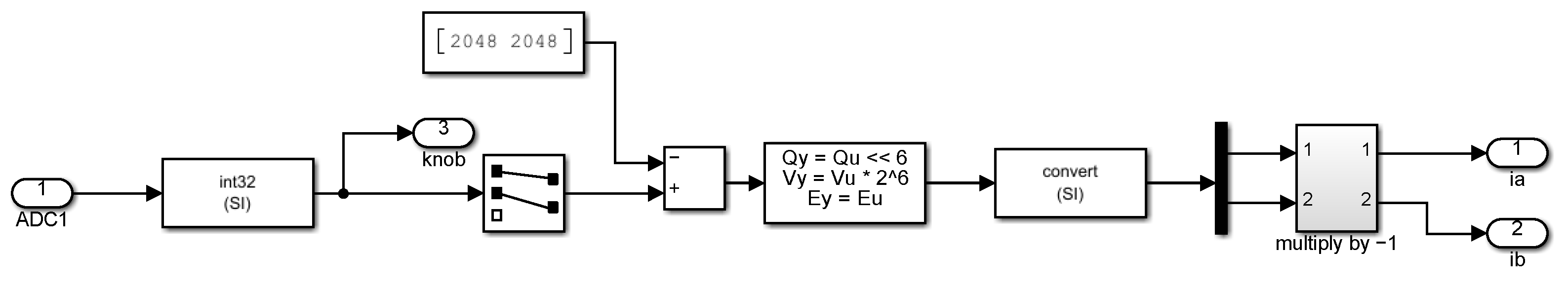
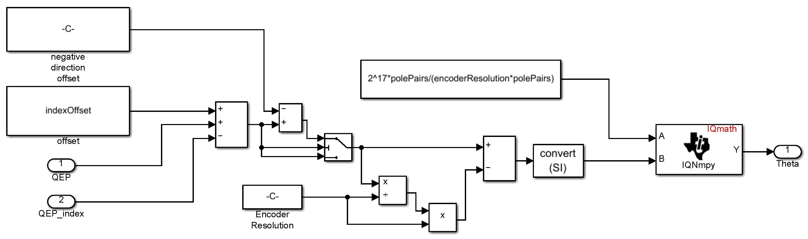
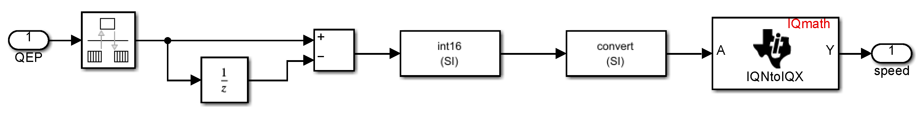
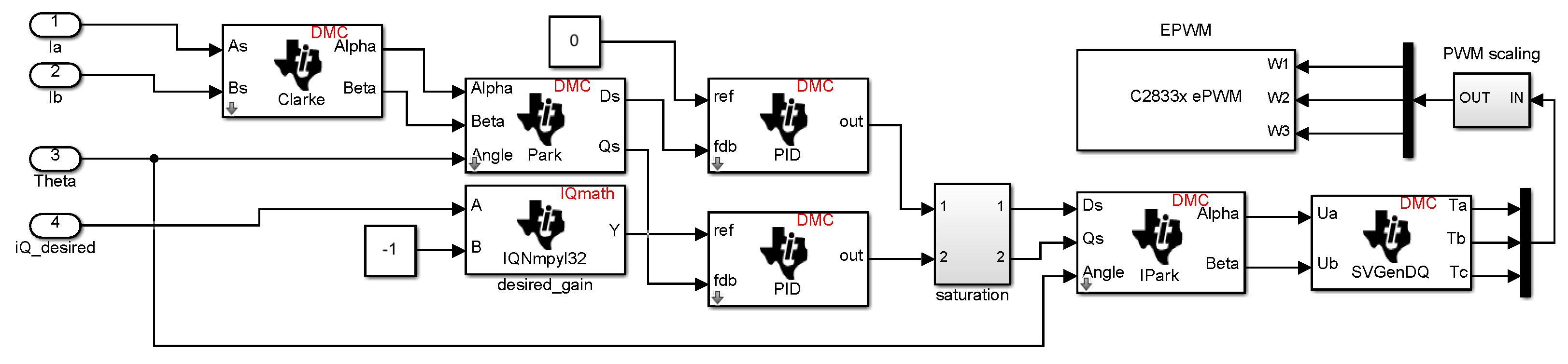
4.2. DSP Peripheral Configuration Based on Model Design

MATLAB provides many hardware support packages, including TI C2000 processor series, for the basic FOC system, which generally need ePWM module, ADC module, eQEP module and interrupt system [29].
The ePWM module is used to generate three complementary PWM waves. The configurable parameters include period, duty cycle, dead time, input polarity and external trigger events, etc. Set the duty cycle as an external input, and calculate the duty cycle, and then it can be linked to the ePWM input pin of the hardware. The external trigger event sets to start ADC conversion, which means that when the bridge arm turns on, the current value at this moment is collected.
The ADC module is used to configure the ADC value represented by the acquisition current, select the corresponding channel, and set it to ePWMxA to trigger the conversion. The data output type is set to uint16. Finally, the conversion completion interrupt needs to be enabled, and the core program of the algorithm needs to be executed in the interrupt.
The eQEP module is used to configure and collect the encoder signal, and then obtain the rotor position, direction, and speed information. For the quadrature photoelectric encoder, the counting mode can be directly set to quadrature counting, which is equivalent to 4 times the counting frequency of QEP, and then improves speed calculation accuracy. In addition, the module also provides a flag pulse QEP_index, the flag bit will generate a pulse for speed calculation every time the motor rotates one revolution.

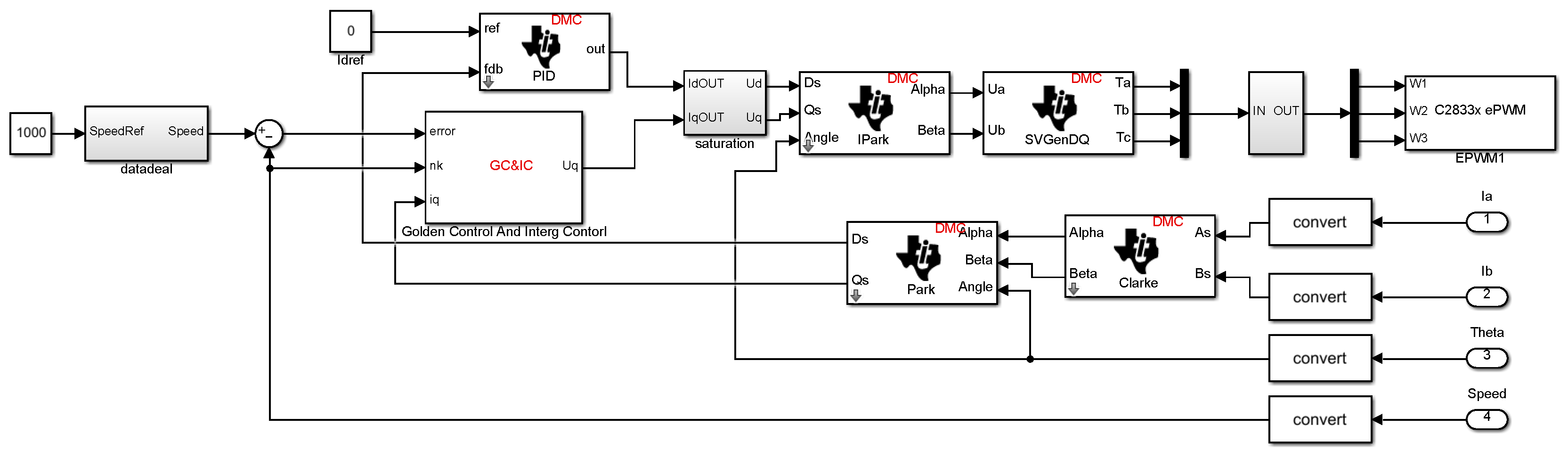
4.3. Build PMSM Golden-Section Adaptive Code Generation Model

In this paper, the model-based design method is used to model and verify the golden-section speed adaptive system. First, the characteristic model algorithm is simulated and analyzed in simulink, and then the model is discretized and converted into an embedded code model for modular testing. Finally, the system integration is carried out, and the generated board file is directly downloaded to the corresponding DSP hardware to verify the correctness and efficiency of the model algorithm.
In order to increase the program processing speed, it is necessary to perform fixed-point processing on the core model, mainly processing the data collected by the ADC and eQEP modules and some mathematical calculation modules. In order to accelerate the processing speed of the program, fixed-point processing is needed for the core model, mainly for the data collected by ADC, eQEP module, and part of the mathematical calculation module.
For the acquisition of phase current, it is only necessary to collect AB two-phase current. Since the ADC of C2000 series is unipolar, it cannot collect negative voltage signals. Bipolar signals need to be biased, and the bias voltage is set to 1.65 V. The current signal can be converted into a 0~3.3 V voltage signal that can be processed by the embedded hardware, and then the collected data is shifted to the left by 6 bits to form a normalized Q17 format, and the output data is set to fixdt (1,32,17). The current acquisition and data conversion model is shown in Figure 4:
For obtaining rotor position and speed, it is divided into electrical Angle calculation and speed calculation modules. The calculation formula of electrical Angle is:
{ N PU = N QEP ( f i x ( N Q E P N PP × R ) × p n × R ) E T h e t a = N PU × p n R
In Equation (16), N P U is the number of counting pulses, N Q E P is the number of encoder pulses, p n is the number of motor poles, R is the number of encoder lines, E T h e t a is the electrical Angle. Since the encoder has a correction angle when the motor is delivered, which is the deviation between the center line of the rotor magnetic field and the zero point of the encoder, the software correction is also required. The electrical Angle model after adding correction and processing Q17 data format is shown in Figure 5:
The rotor speed is calculated by M-method, and the expression is:
ω e ( k ) = θ e ( k ) θ e ( k 1 ) f b × T
In Equation (17), θ e is the electrical Angle of the rotor position, f b is the reference frequency, and T is the sampling period. The speed calculation model is shown in Figure 6:
Combining the phase current acquisition and rotor information acquisition models, the FOC model of embedded automatic code generation is built as shown in Figure 7. On this basis, the PI controller of the q-axis is replaced by the discrete model of the golden-section adaptive method described in the paper, which constitutes the automatic code generation model of the golden-section-based rotational speed adaptive control system as shown in Figure 8.

5. Simulation and Experimental Research

The control chip used in this paper is TMS320F28335, with a floating point processing unit, and the motor is a surface mount low-voltage permanent magnet synchronous motor, whose specific parameters are shown in Table 1. The actual hardware of the overall system is shown in Figure 9. the speed sensor is an incremental photoelectric encoder, its model is H40-6-0500VL, 500 pulses per circle, and maximum support speed is 8000 rpm. This platform is used as the verification system to verify the PMSM’s linear golden-section rotational speed adaptive control system.

5.1. Simulation Analysis

5.1.1. Influence of Filter Coefficient on the System

The golden-section speed adaptive control scheme is sensitive to step signals, so first-order low-pass filtering is used to process the input reference signals. The filtering coefficient has different influences on the system results. The reference speed is set at 1000 RPM and the simulation time is 0.1 s and Figure 10, Figure 11, Figure 12 and Figure 13 show the speed response curves under different values.
As can be seen from Figure 10, Figure 11, Figure 12 and Figure 13, the larger α is, the shorter its adjustment time. Meanwhile, the initial error is large, and the system oscillates. The smaller α is, the more stable its speed tracking, and the smaller the error, but it will increase the system adjustment time and reduce the adjustment sensitivity. Considering the stability and rapidity of the system comprehensively, filter coefficient α = 0.002 is selected, and the speed error curve is shown in Figure 14.

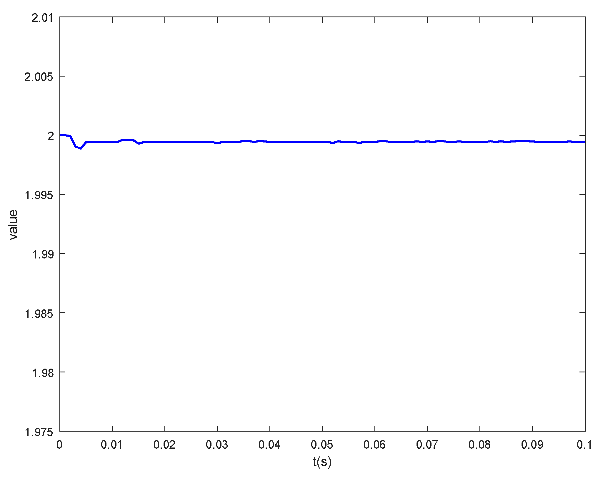
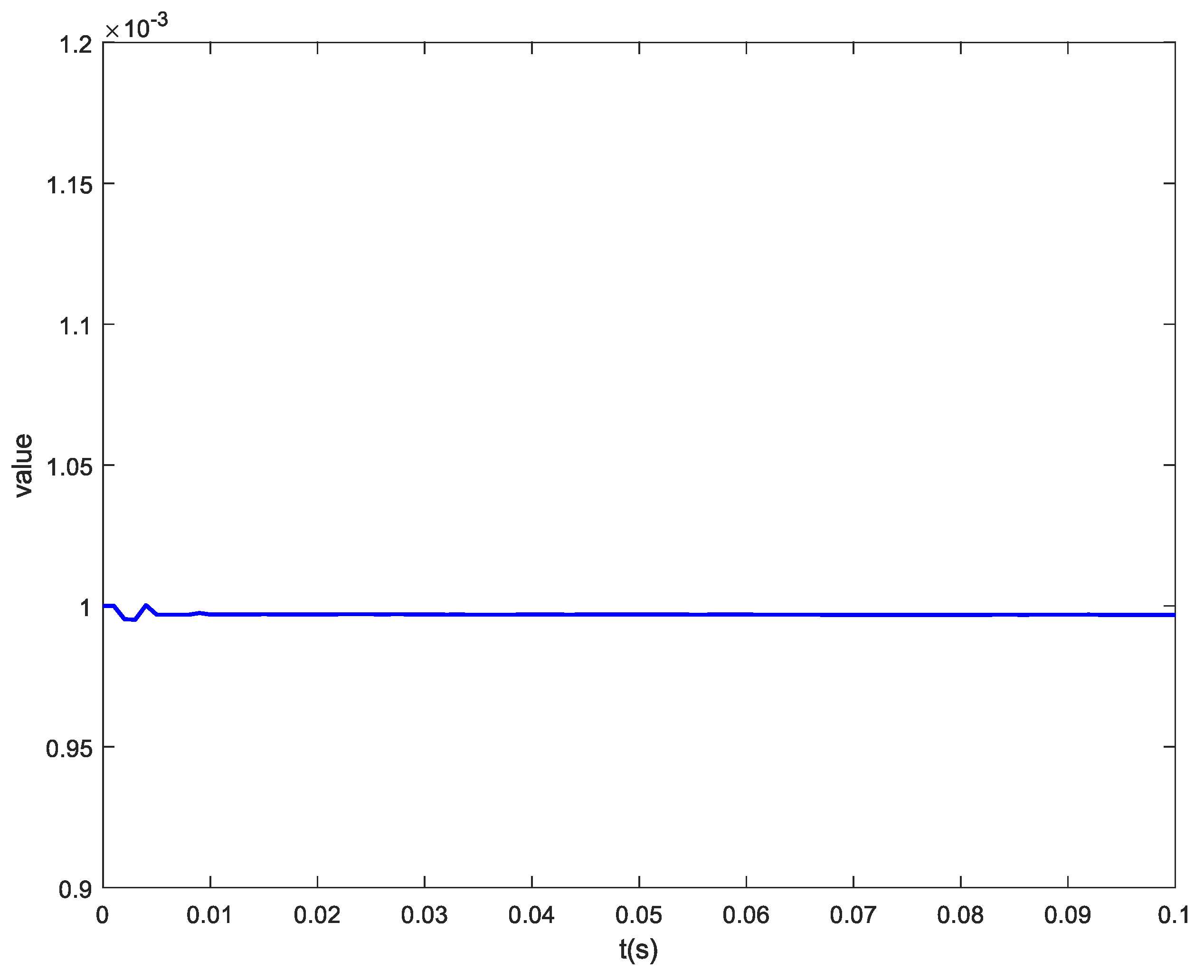
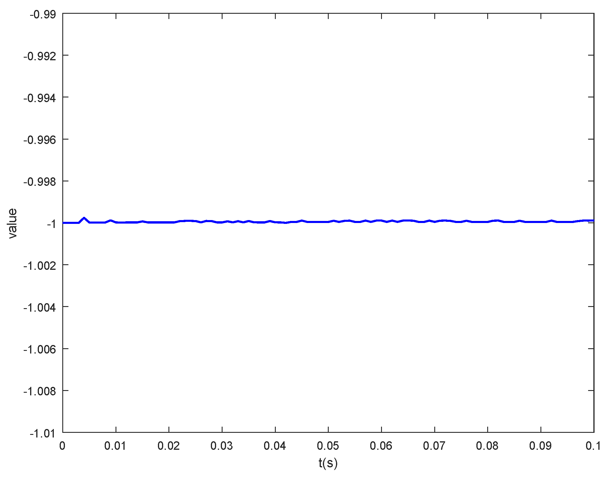
5.1.2. Parameter Identification Results and Analysis

When the sampling time is small enough, the range of characteristic parameters f 1 ( k ) ( 1 , 2 ] f 2 ( k ) [ 1 , 0 ) g 0 ( k ) 1 , generally, takes the initial value of parameter identification f 1 ( k ) = 2 f 2 ( k ) = 1 g 0 ( k ) = 0.001 . Set the simulation time to 0.1 s, the reference speed to 1000 rpm, and the filter coefficient α = 0.002 . Figure 15, Figure 16 and Figure 17 show the online parameter identification results of the second-order characteristic model. It can be seen from the figure that the identification parameters have little change after steady-state operation, which further indicates that the speed adaptive system has strong stability.

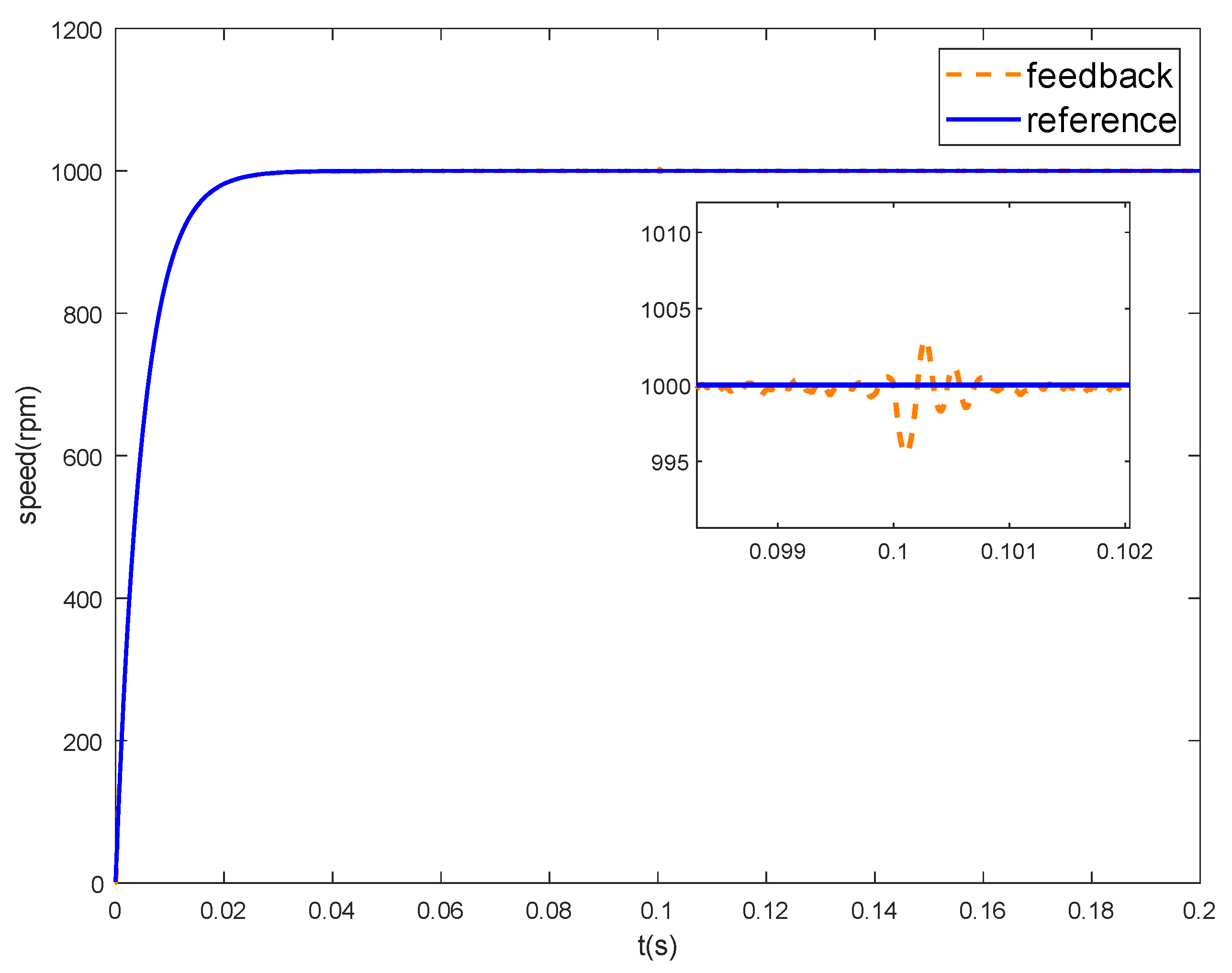
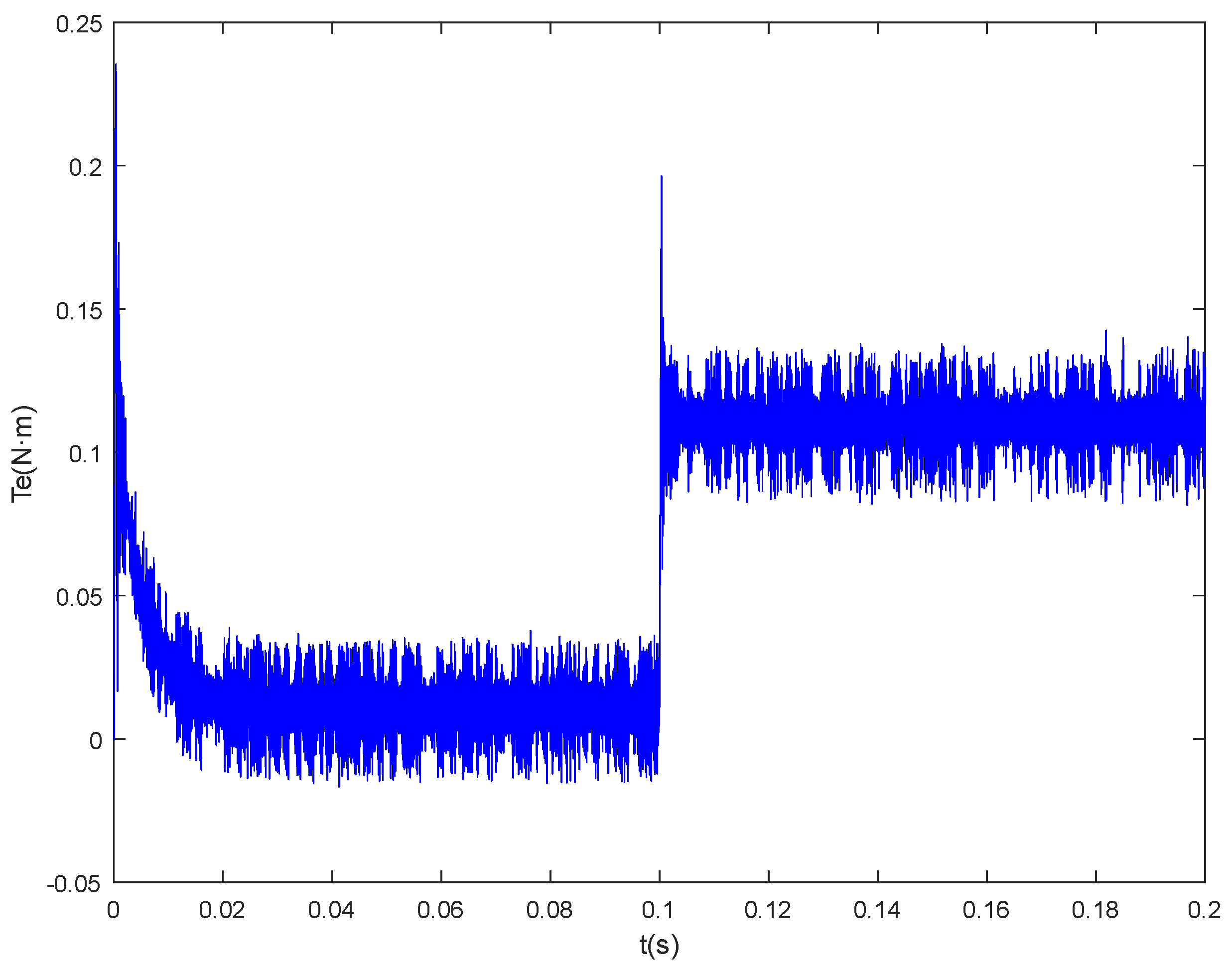
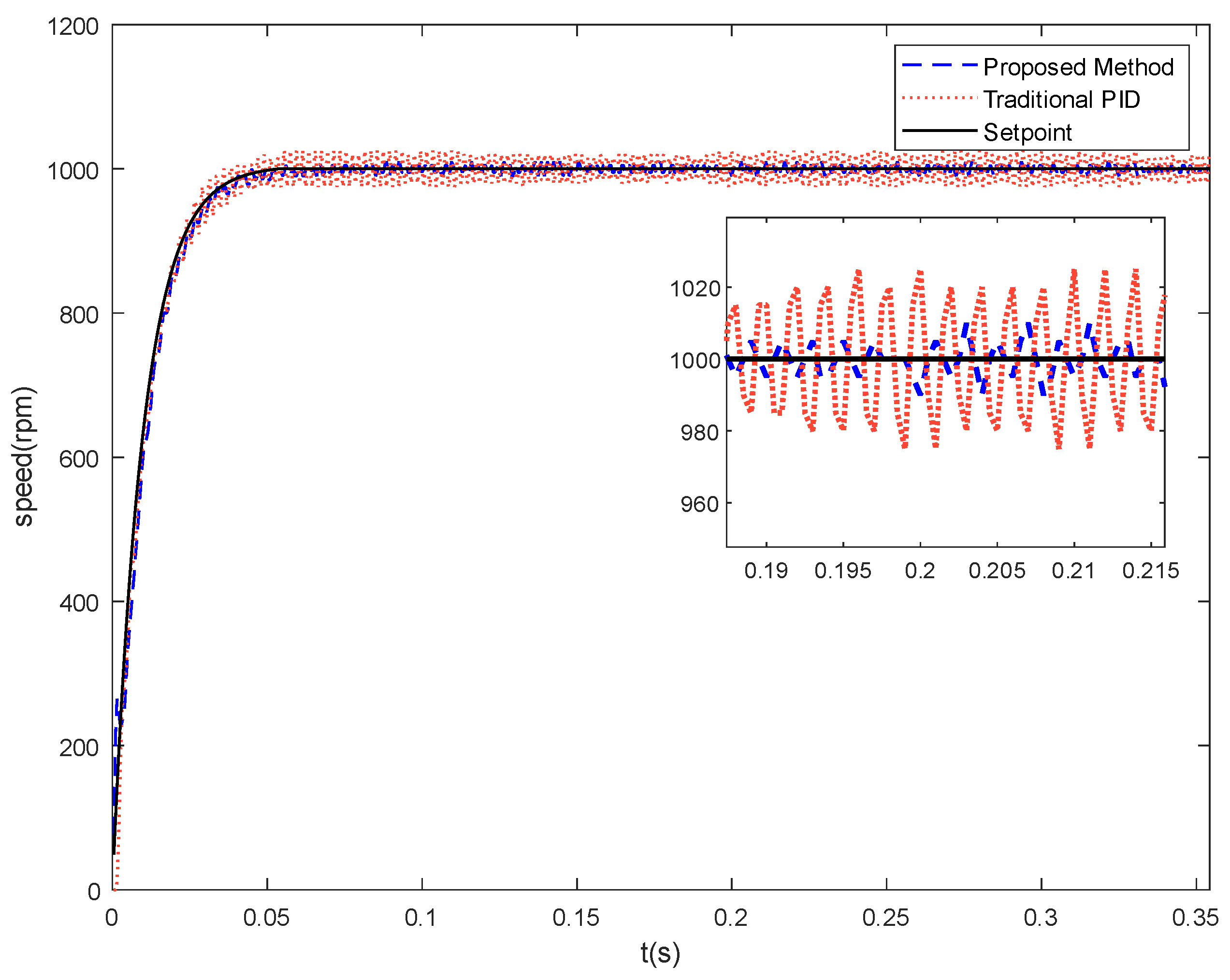
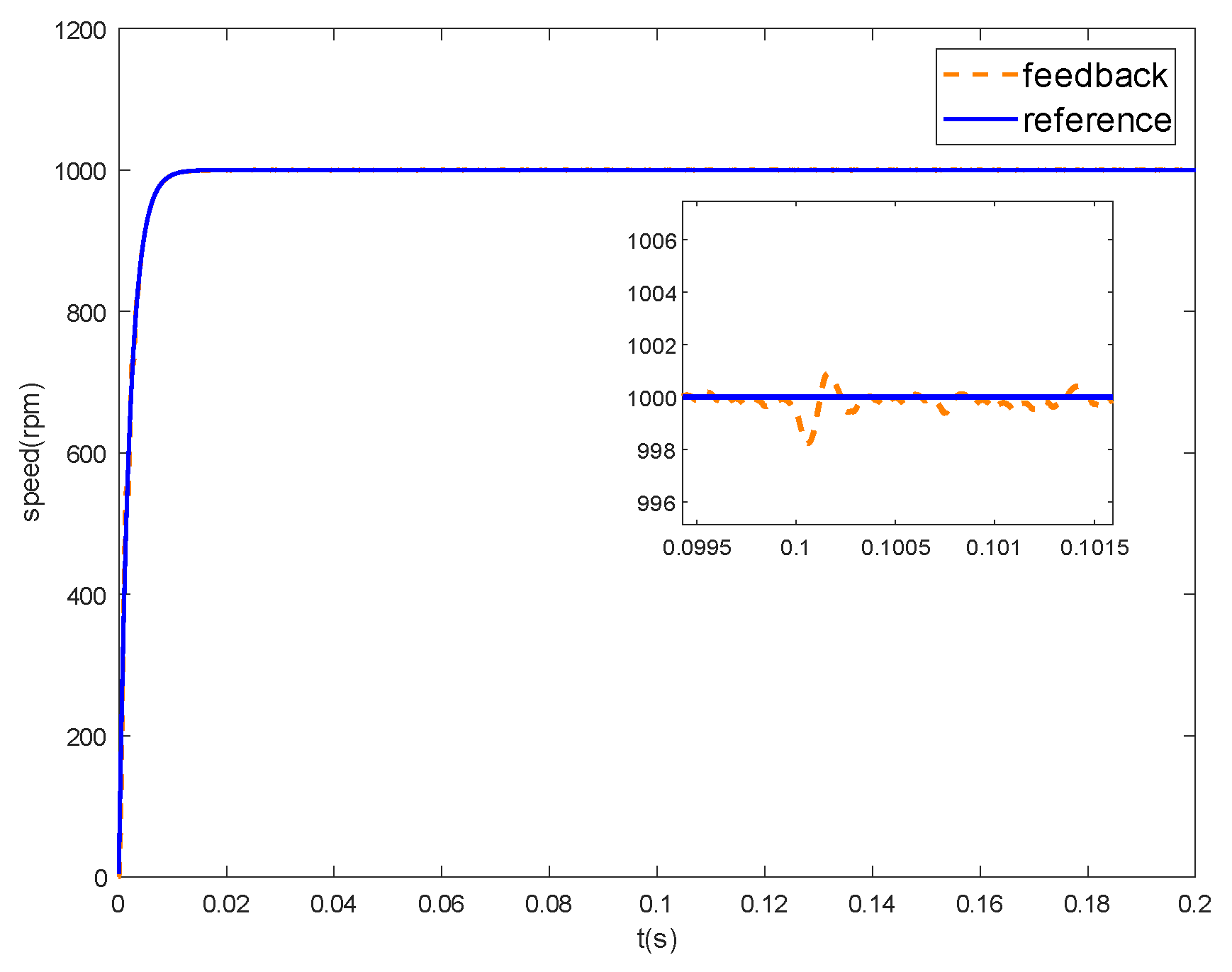
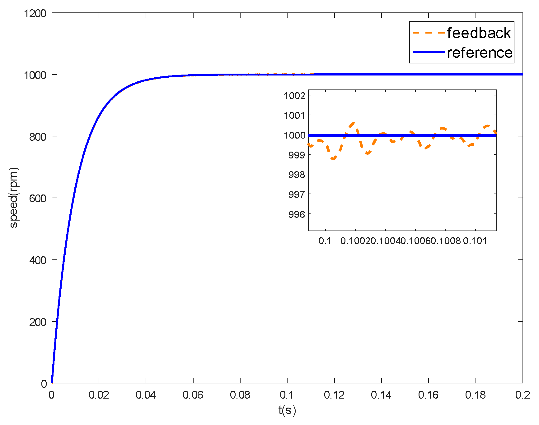
5.1.3. Load Performance Analysis

In order to verify the anti-disturbance of the proposed method, a loading simulation experiment was carried out on the system. The rated torque of the motor used was 0.318 N·m, the sudden load was set at 0.1 s, and the loading value was 0.1 N·m. Figure 18 shows the speed response curve, and Figure 19 shows the curve of torque. It can be seen from the figure that in the process of steady-state operation, the impact of sudden load on the system speed can be ignored, indicating that the proposed method has a high anti-disturbance ability.

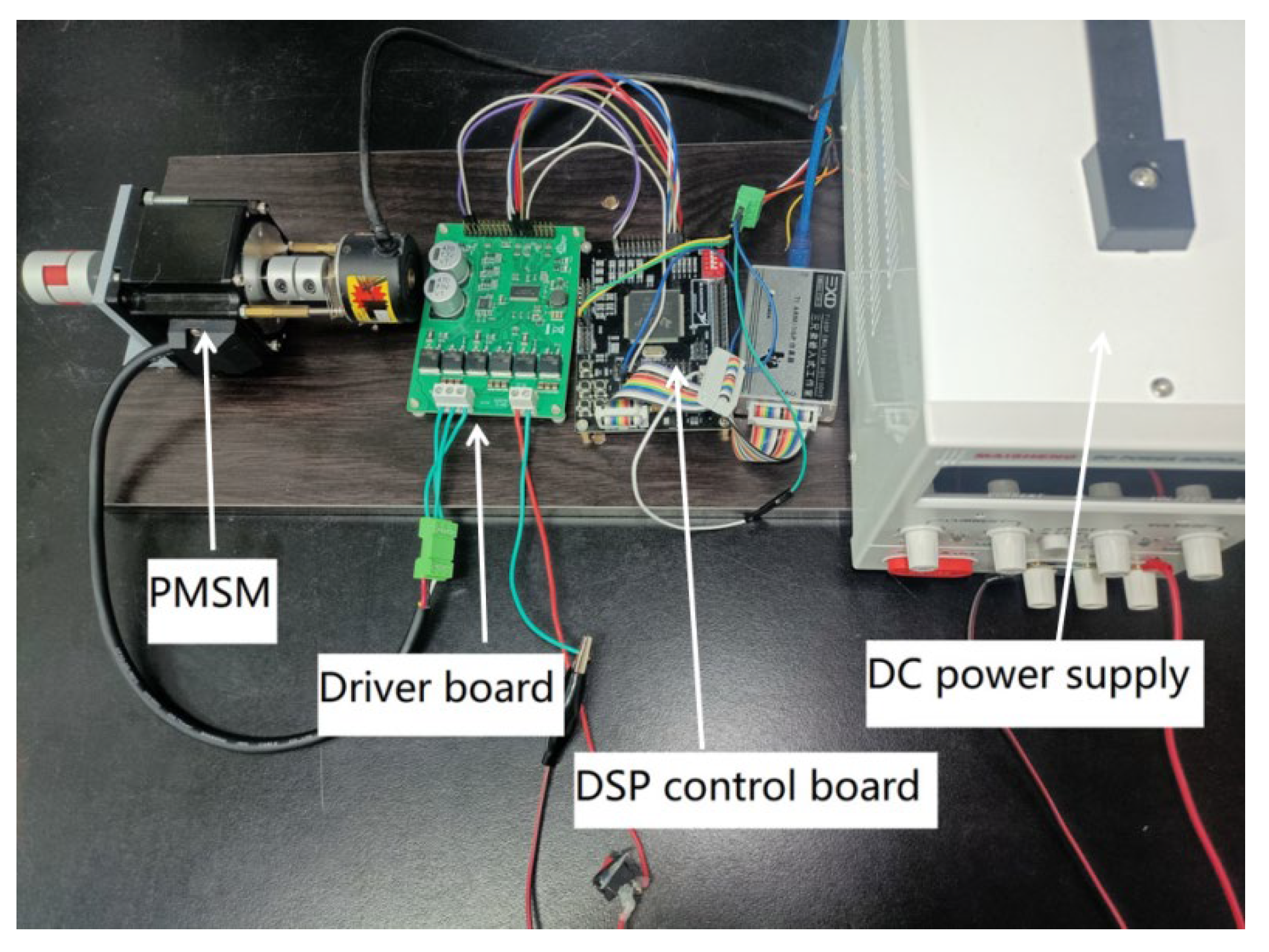
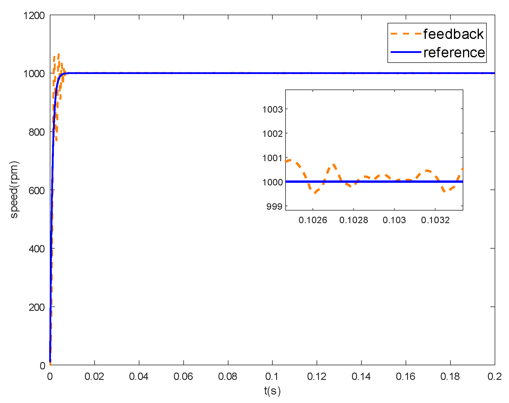
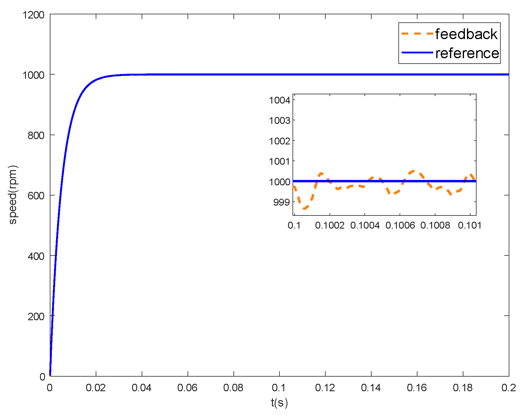
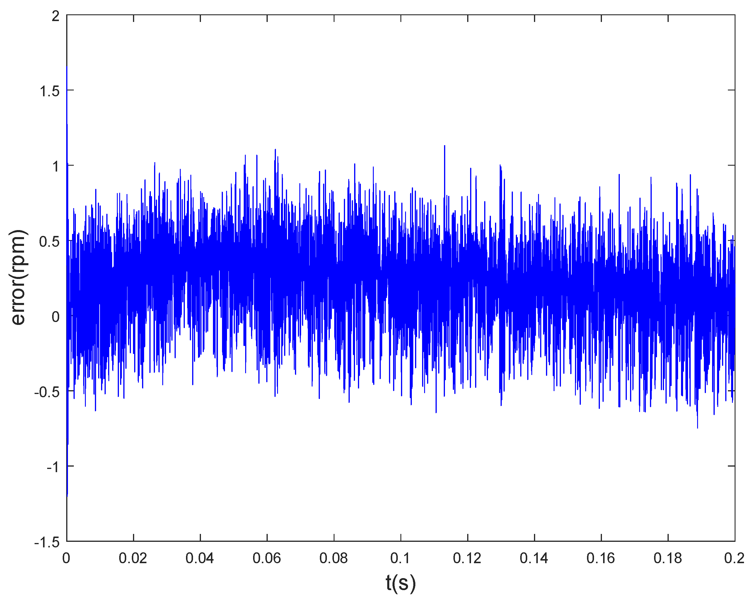
5.2. Actual Product to Verify

Physical verification is the key link of model-based design, which determines the feasibility of the proposed method. After the correct simulation verification, the core algorithm needs to be discretized, and then the system motor in the simulation is replaced by the actual motor feedback value which is combined with the hardware.
In this paper, the recursive parameter identification model, the golden-section model, and the integral model are firstly discretized, and then the data is converted into per-unit values. The reference value selects the rated value of the motor. The generated FOC framework interface is connected, and finally, the model is compiled and downloaded to the hardware core unit and optimized to complete the physical verification process. In order to illustrate the performance superiority of the method proposed in this paper, the golden-section controller with integral compensation based on the characteristic model is compared with the traditional PID, and the PMSM in Table 1 and the hardware system in Figure 9 are used for verification, and the speed reference value is set to 1000 rpm. Figure 20 is the actual operation effect of the traditional PID and the method proposed in this paper.
Figure 20 shows that the performance of the proposed method is significantly better than that of traditional PID control. However, it is limited by hardware, such as encoder accuracy, current sampling accuracy, etc. The error of actual operation is larger than that of simulation, which can be improved by improving hardware performance.
In order to highlight the actual performance of the proposed method, settling time and average volatility are introduced, where, average volatility is defined as the ratio of the absolute value of the steady-state error to the reference value. Table 2 shows the running results of the proposed method about linear golden-section control (LGSC), nonlinear golden-section control (NGSC), and PID control. They were all carried out on the same experimental platform with reference speed set to 1000 rpm and the frequency of the control system was set to 20 KHz.
As can be seen from Table 2, our method has better performance than the results of nonlinear golden-section control and traditional PID control. The proposed method does not contain high-order terms, so it has fast regulation speed, which makes it superior to NGSC and PID in rapidity. In terms of average volatility, for the same experimental platform, after the motor enters steady-state operation, the average speed error of the proposed method is 2.3 rpm, the average speed error of NGSC is 4.3 rpm, while the traditional PID is as high as 11 rpm, which shows that the characteristic model and golden-section control have advantages in control accuracy. In conclusion, the proposed method has advantages in rapidity and accuracy.

6. Conclusions

In view of the difficulty of establishing an accurate mathematical model for PMSM, and the introduction of new algorithms increasing the difficulty of embedded code development, this paper adopts the model-based design method on the basis of the characteristic model, and introduces the linear golden-section and integral compensation controller. The speed adaptive control of PMSM is carried out, and the simulation and physical verification tests are carried out. In addition, the first-order low-pass filter is used to process the reference signal, and the influence of different filter coefficients on the result is discussed. Finally, a more suitable coefficient value is selected, which gives the system rapidity but also solves the overshoot problem. Meanwhile, the model-based design method is used to verify the proposed control scheme, and the performance comparison with traditional PID control and nonlinear golden-section control is given. The experiment shows that compared with traditional PID control, the speed control accuracy of PMSM is improved about 3.8 times. In the future, we plan to reduce the order of the characteristic model and use the first-order characteristic model to reduce the identification parameters and further improve the system response speed under the premise of ensuring accuracy.

Author Contributions

Conceptualization and methodology, W.J. and W.H.; software, validation, investigation and writing—original draft preparation, W.H.; formal analysis, L.W.; resources, Z.L.; project administration, W.D. All authors have read and agreed to the published version of the manuscript.

Funding

This research was funded by Shanghai Institute of Technology, grant number XTCX2021-10.

Institutional Review Board Statement

Not applicable.

Informed Consent Statement

Not applicable.

Data Availability Statement

Not applicable.

Conflicts of Interest

The authors declare no conflict of interest.

References

  1. Wang, G.; Valla, M.; Solsona, J. Position Sensorless Permanent Magnet Synchronous Machine Drives—A Review. IEEE Trans. Ind. Electron. 2019, 67, 5830–5842. [Google Scholar] [CrossRef]
  2. Lin, R.; Chen, S.; Ding, X. Modeling and Simulation of Neuron Integral-separated PID Control for Permanent Magnet Synchronous Motor. J. Fuzhou Univ. 2009, 37, 849–852. [Google Scholar]
  3. Ding, W.; Gao, L. Modeling and Simulation of Permanent Magnet Synchronous Motor Vector Control System. Micromotors 2010, 43, 66–71. [Google Scholar] [CrossRef]
  4. Liu, Z.G.; Wang, J.Z. Design of Neural Network Adaptive Sliding Mode Controller for Permanent Magnet Synchronous Motor. Electr. Mach. Control. 2009, 13, 290–295. [Google Scholar] [CrossRef]
  5. Ma, H.C. Design of a New Sliding Mode Speed Controller for Permanent Magnet Low Speed Synchronous. Motor. Control. Eng. China 2016, 23, 1757–1762. [Google Scholar] [CrossRef]
  6. Chen, Z.; Zhang, Z.H. Current Decoupling and Harmonic Suppression Strategy of Permanent Magnet Synchronous Motor Based on Proportional Resonant Active Disturbance Rejection Control. Proc. CSEE 2021, 58, 1–10. [Google Scholar] [CrossRef]
  7. Sha, L.; Song, Y.; Li, Z. Permanent Magnet Synchronous Motor Control Method Based on Fuzzy PI and Sliding Mode Observer. J. Phys. Conf. Ser. IOP Publ. 2022, 2218, 012053. [Google Scholar] [CrossRef]
  8. Ding, X.; Li, R.; Cheng, Y.; Liu, Q.; Liu, J. Design of and Research into a Multiple-Fuzzy PID Suspension Control System Based on Road Recognition. Processes 2021, 9, 2190. [Google Scholar] [CrossRef]
  9. Wang, A.P.; Huang, X.Z. Variable Weight Coefficient Multi-step Model Predictive Current Control Method for Permanent Magnet Linear Synchronous Motor. Proc. CSEE 2022, 59, 1–11. [Google Scholar] [CrossRef]
  10. Yang, P.M.; Liu, Y.C. Voltage Stability Control Strategy Based on Model Predictive Current Compensation. Micromotors 2022, 55, 56–64. [Google Scholar] [CrossRef]
  11. Bai, C.G.; Wei, X.J. Research on Nonlinear Active Disturbance Rejection Compound Control Strategy of Permanent Magnet Synchronous Motor. Small Spec. Electr. Mach. 2021, 49, 46–50. [Google Scholar] [CrossRef]
  12. Liu, C.; Hu, J.H. Torque Ripple Suppression Strategy of Open-winding Permanent Magnet Synchronous Motor with Common DC Bus Based on Improved Active Disturbance Rejection Control. Proc. CSEE 2022, 59, 1–12. [Google Scholar] [CrossRef]
  13. Tavoosi, J. PMSM Speed Control Based on Intelligent Sliding Mode Technique. COMPEL-Int. J. Comput. Math. Electr. Electron. Eng. 2020, 39, 1315–1328. [Google Scholar] [CrossRef]
  14. Tavoosi, J.; Shirkhani, M.; Abdali, A.; Mohammadzadeh, A.; Nazari, M.; Mobayen, S.; Asad, J.H.; Bartoszewicz, A. A New General Type-2 Fuzzy Predictive Scheme for PID Tuning. Appl. Sci. 2021, 11, 10392. [Google Scholar] [CrossRef]
  15. Chen, J.; Wang, J.; Yan, B. Simulation Research on Deadbeat Direct Torque and Flux Control of Permanent Magnet Synchronous Motor. Energies 2022, 15, 3009. [Google Scholar] [CrossRef]
  16. Zhong, Z.; You, J.; Zhou, S. Torque Ripple Reduction of DTC Based on An Analytical Model of PMSM. World Electr. Veh. J. 2020, 11, 28. [Google Scholar] [CrossRef] [Green Version]
  17. Li, Y.-H.; Wu, T.-X.; Zhai, D.-W.; Zhao, C.-H.; Zhou, Y.-F.; Qin, Y.-G.; Su, J.-S.; Qin, H. Hybrid Decision Based on DNN and DTC for Model Predictive Torque Control of PMSM. Symmetry 2022, 14, 693. [Google Scholar] [CrossRef]
  18. Mahfoud, S.; Derouich, A.; El Ouanjli, N.; Quynh, N.V.; Mossa, M.A. A New Hybrid Ant Colony Optimization Based PID of the Direct Torque Control for a Doubly Fed Induction Motor. World Electr. Veh. J. 2022, 13, 78. [Google Scholar] [CrossRef]
  19. Dou, X.H.; Wang, Y. Golden Section Adaptive Control of Permanent Magnet Synchronous Motor. Electron. Technol. 2015, 44, 18–22. [Google Scholar] [CrossRef]
  20. Dou, X.H.; Wang, Y. Nonlinear Golden-section Adaptive Control of Permanent Magnet Synchronous Motor. J. Syst. Sci. Math. Sci. 2015, 35, 860. [Google Scholar] [CrossRef]
  21. Wu, H.; HU, J. Intelligent Adaptive Control Based on Characteristic Model; China Science and Technology Press: Beijing, China, 2009; pp. 55–67. [Google Scholar]
  22. Han, Z.G. A New Method of Dynamic System Forecasting. Acta Autom. Sin. 1983, 21, 161–168. [Google Scholar] [CrossRef]
  23. Cao, Y.; Guo, J. Adaptive Anti-saturation Control of High Speed Motor Based on Characteristic Model. Electr. Mach. Control. 2021, 25, 86–93. [Google Scholar] [CrossRef]
  24. Wang, Y.; Yu, H.; Che, Z.; Wang, Y.; Liu, Y. The Direct Speed Control of Pmsm Based on Terminal Sliding Mode and Finite Time Observer. Processes 2019, 7, 624. [Google Scholar] [CrossRef] [Green Version]
  25. Shi, J.Z.; You, D.M. Golden Section Adaptive Speed Control of Ultrasonic Motors. Trans. China Electrotech. Soc. 2013, 28, 59–65. [Google Scholar] [CrossRef]
  26. Wu, J.R.; Guo, Y. Adaptive Control of Dual Motor Servo System Based on Characteristic Model. J. Huazhong Univ. Sci. Technol. 2013, 41, 436–439. [Google Scholar] [CrossRef]
  27. Wang, S.W.; Wang, S.D. Research on Automatic Code Generation Technology of SVPWM Algorithm Based on Model Design. Electr. Eng. 2018, 24, 134–136. [Google Scholar] [CrossRef]
  28. Wu, Z.J.; Li, J.G. Research on Automatic Code Generation for Permanent Magnet Synchronous Motor Control. Mach. Des. Manuf. 2021, 10, 182–185. [Google Scholar] [CrossRef]
  29. Yan, F.C.; Zhao, Y.X. Vector Control of Permanent Magnet Synchronous Motor Based on Matlab and CCS. Micromotors 2017, 50, 60–64. [Google Scholar] [CrossRef]
Figure 1. Diagram of FOC vector control system.
Processes 10 01010 g001
Figure 2. Golden-section speed adaptive system structure diagram.
Processes 10 01010 g002
Figure 3. The general process of model-based design.
Processes 10 01010 g003
Figure 4. Current acquisition model.
Processes 10 01010 g004
Figure 5. Electrical Angle calculation model.
Processes 10 01010 g005
Figure 6. Rotational speed calculation model.
Processes 10 01010 g006
Figure 7. DSP automatic code generation model for FOC system.
Processes 10 01010 g007
Figure 8. Golden-section speed adaptive code generation model.
Processes 10 01010 g008
Figure 9. PMSM hardware diagram.
Processes 10 01010 g009
Figure 10. Speed response curve when α = 0.01.
Processes 10 01010 g010
Figure 11. Speed response curve when α = 0.005.
Processes 10 01010 g011
Figure 12. Speed response curve when α = 0.002.
Processes 10 01010 g012
Figure 13. Speed response curve when α = 0.001.
Processes 10 01010 g013
Figure 14. Speed error curve when α = 0.002.
Processes 10 01010 g014
Figure 15. Characteristic parameter identification curve of f 1 ( k ) .
Processes 10 01010 g015
Figure 16. Characteristic parameter identification curve of f 2 ( k ) .
Processes 10 01010 g016
Figure 17. Characteristic parameter identification curve of g 0 ( k ) .
Processes 10 01010 g017
Figure 18. Curve of speed after sudden loading.
Processes 10 01010 g018
Figure 19. Curve of torque for sudden loading.
Processes 10 01010 g019
Figure 20. Actual operation effect of traditional PID and proposed method.
Processes 10 01010 g020
Table 1. PMSM parameters.
ParameterValue
Rated voltage (V)36
Rated current (A)4.6
Pole pairs4
Phase resistance (Ω)0.38
Phase inductance (mH)1
Coefficient of viscous friction ( N · m · s )0.0001
Moment of inertia ( kg · cm 2 )0.0588
Magnetic flux amplitude (Wb)0.11867
Rated torque (N)0.318
Table 2. Performance analysis of different control methods.
MethodSettling Time/msAverage Volatility/%
LGSC140.23
NGSC350.43
PID2601.10
Publisher’s Note: MDPI stays neutral with regard to jurisdictional claims in published maps and institutional affiliations.

