
Topology Optimization Combined with a Parametric Algorithm for Industrial Synchronous Reluctance Motor Design

Abstract
:1. Introduction
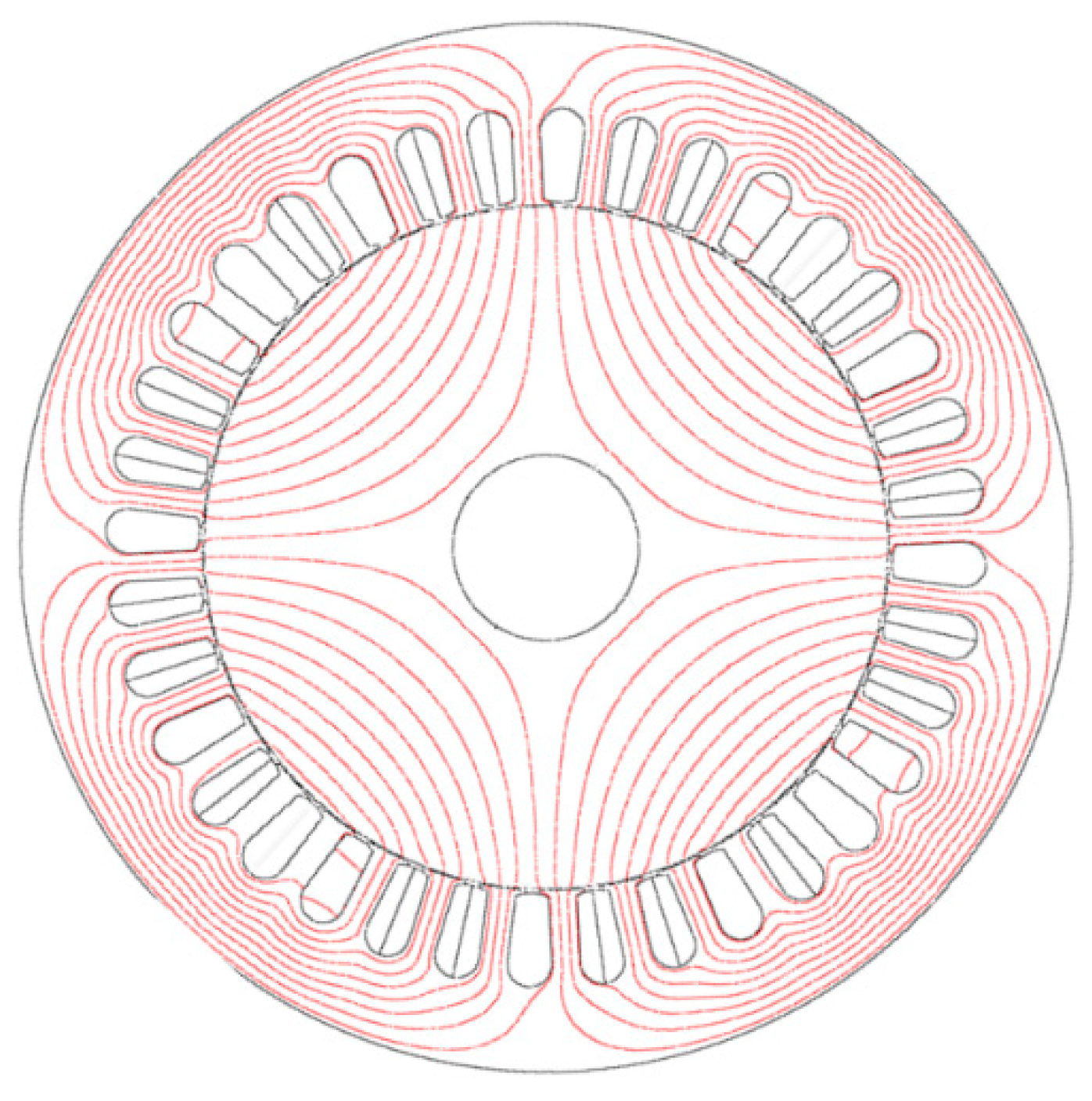
2. Analyzed Synchronous Reluctance Motor
3. Optimization Process
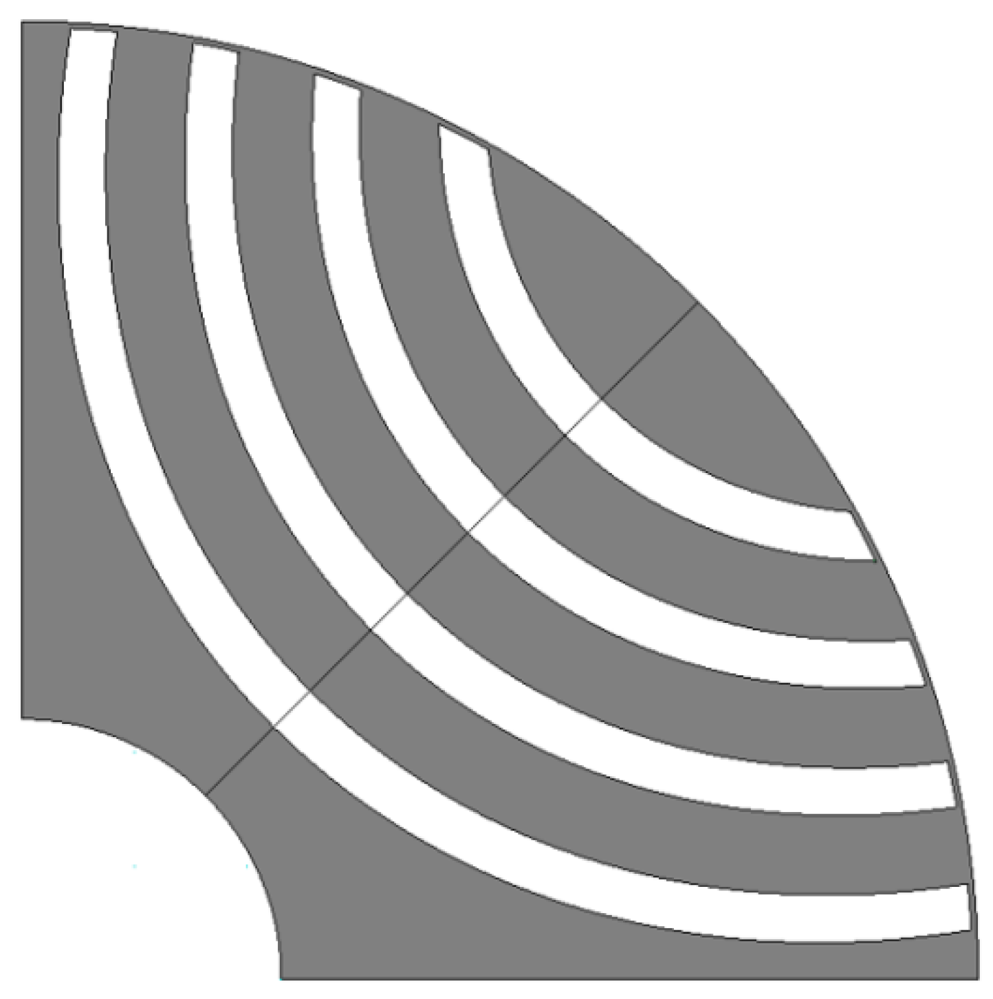
3.1. Oval Mesh Grid
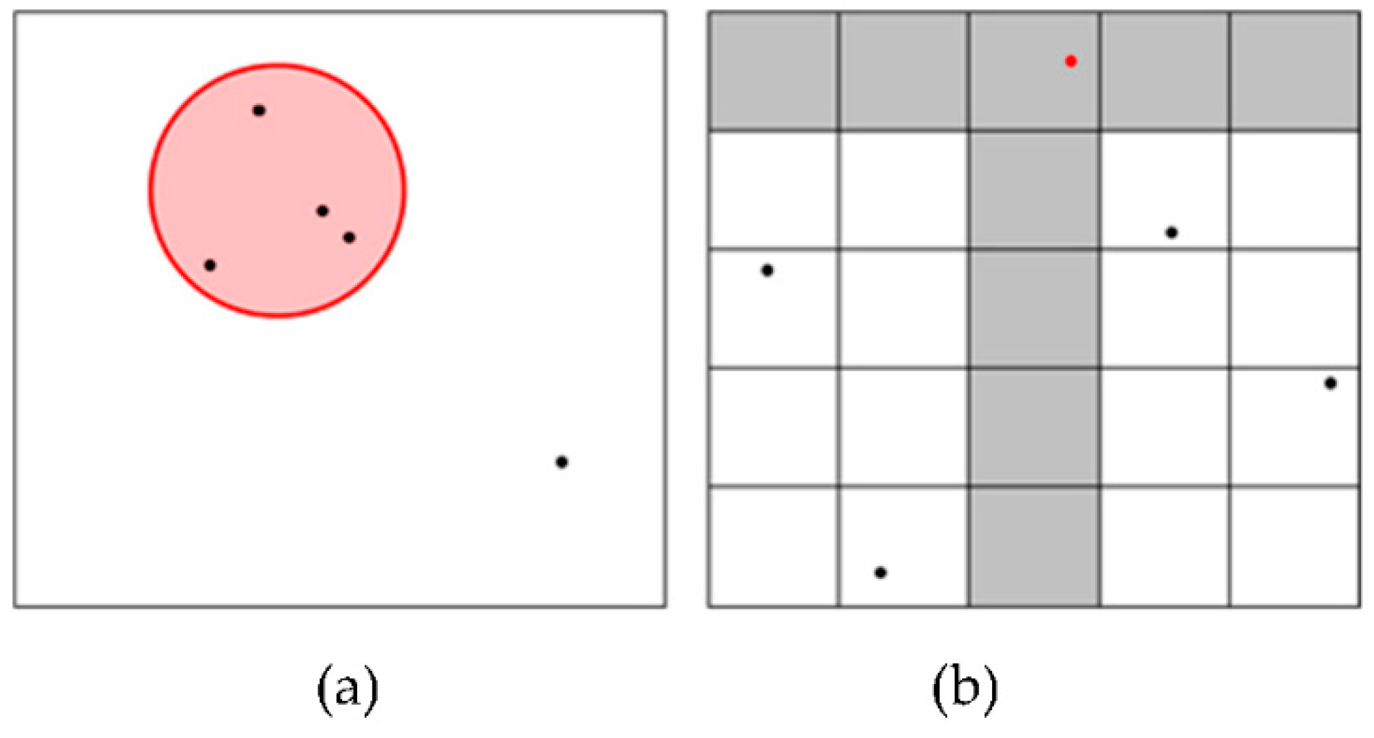
3.2. ON–OFF Method
- (Processes 1) The initial model and mesh grid are set.
- (Processes 2) The objective function value of the initial model is calculated through FEM.
- (Processes 3) The objective function value of the model in which one cell is changed from the initial model is obtained. This repeats i from one to the last cell number.
- (Processes 4) If the objective function value of model i is better than the existing value, the material of cell i is changed.
- (Processes 5) At this time, to prevent over convergence, the material change factor P, which is a value between zero and one, is used, and the cells corresponding to 1-P of the entire lower level are not changed.
- (Processes 6) Processes 2–4 are repeated until there are no more changed cells.
3.3. Smoothing
3.4. Skew
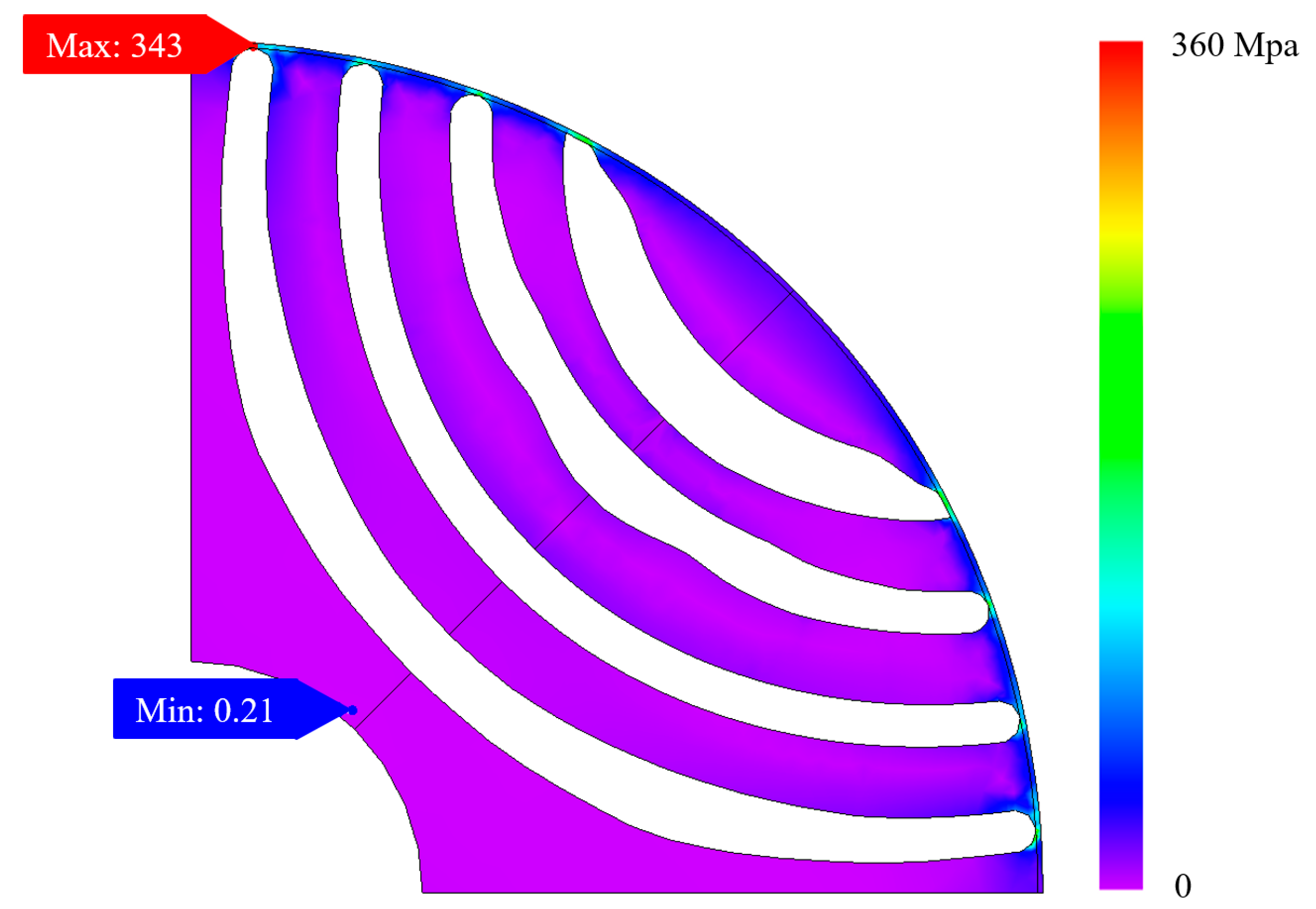
3.5. Stress Analysis
4. Conclusions
- -
- The optimization process for the initial design, mesh grid setting, and boundary surface ON–OFF method are the most efficient ways to use TO.
- -
- The TOCPA applied determines an optimal design that breaks stereotypes. This cannot be achieved with conventional optimization methods using a limited number of design variables.
- -
- Finally, a ratio-based smoothing technique was applied that can reduce the manufacturing difficulty and obtain additional performance improvements.
Author Contributions
Funding
Institutional Review Board Statement
Informed Consent Statement
Data Availability Statement
Acknowledgments
Conflicts of Interest
References
- Zou, G.; Cai, S. Research on Chinese rare earth industry government regulation based on SCP theory paradigm. In Proceedings of the International Conference on Remote Sensing 2011, Environment and Transportation Engineering, Nanjing, China, 24–26 June 2011; Volume 27. [Google Scholar]
- De Martin, M.; Luise, F.; Pieri, S.; Tessarolo, A.; Poloni, C. Numerical multi-objective optimization of a squirrel cage induction motor for industrial application. In Proceedings of the 2015 International Aegean Conference on Electrical Machines & Power Electronics (ACEMP), Side, Turkey, 2–4 September 2015. [Google Scholar]
- Li, H.; Curiac, R.S. Designing More Efficient Large Industrial Induction Motors by Utilizing the Advantages of Adjustable-Speed Drives. IEEE Trans. Ind. Appl. 2010, 46, 1805–1809. [Google Scholar] [CrossRef]
- Staton, D.; Boglietti, A.; Cavagnino, A. Solving the More Difficult Aspects of Electric Motor Thermal Analysis in Small and Medium Size Industrial Induction Motors. IEEE Trans. Energy Convers. 2005, 20, 3. [Google Scholar] [CrossRef] [Green Version]
- Maljkovic, Z.; Cettolo, M.; Pavlica, M. The Impact of the Induction Motor on Short-Circuit Current. IEEE Ind. Appl. Mag. 2001, 7, 11–17. [Google Scholar] [CrossRef]
- Waide, P.; Brunner, C.U. Energy-Efficiency Policy Opportunities for Electric Motor-Drive Systems; International Energy Agency: Paris, France, 2011. [Google Scholar]
- Jeong, S.-W. Optimal Design of IE4 Super Premium Efficiency Synchronous Reluctance Motor for Industrial Applicatio. Master’s Thesis, Department Electrical and Information Engineering, Seoul University, Seoul, Korea, 2020. [Google Scholar]
- Park, J.H.; Seo, J.H.; Cha, C.H.; Lee, J. Characteristics Analysis of 15kW Industrial Machine using Synchronous Reluctance Motor for High Efficiency. In Proceedings of the 2013 International Conference on Electrical Machines and Systems (ICEMS), Busan, Korea, 26–29 October 2013. [Google Scholar]
- Weigel, T. Control of Synchronous Reluctance Motors without Encoder for Industrial Applications. In Proceedings of the 2016 6th International Electric Drives Production Conference, Nuremberg, Germany, 30 November–1 December 2016. [Google Scholar]
- Miller, T.J.E.; Hutton, A.; Cossar, C.; Staton, D.A. Design of a Synchronous Reluctance Motor Drive. IEEE Trans. Ind. Appl. 1991, 27, 741–749. [Google Scholar] [CrossRef]
- Kang, Y.-R.; Son, J.-C.; Lim, D.-K. Optimal Design of IPMSM for Fuel Cell Electric Vehicles Using Autotuning Elliptical Niching Genetic Algorithm. IEEE Access 2020, 8, 117405–117412. [Google Scholar] [CrossRef]
- Lee, T.H.; Kang, Y.R.; Son, J.C.; Lim, D.K. Optimized Design of Permanent Magnet Assisted Synchronous Reluctance Motor Using Oriented Auto-tuning Niching Algorithm. J. Electr. Eng. Technol. 2021, 16, 1495–1503. [Google Scholar] [CrossRef]
- Son, J.-C.; Ahn, J.-M.; Lim, J.-W.; Lim, D.-K. Optimal Design of PMa-SynRM for Electric Vehicles Exploiting Adaptive-Sampling Kriging Algorithm. IEEE Access 2021, 9, 41174–41183. [Google Scholar] [CrossRef]
- Liu, X.; Fu, W.N. A Dynamic Dual-Response-Surface Methodology for Optimal Design of a Permanent-Magnet Motor Using Finite-Element Method. IEEE Trans. Magn. 2016, 52, 7204304. [Google Scholar] [CrossRef]
- Mohanarajah, T.; Rizk, J.; Nagrial, M.; Hellany, A. Design Optimisation of Flux Barrier Synchronous Reluctance Machines. In Proceedings of the 2015 Intl Aegean Conference on Electrical Machines & Power Electronics (ACEMP), 2015 Intl Conference on Optimization of Electrical & Electronic Equipment (OPTIM) & 2015 Intl Symposium on Advanced Electromechanical Motion Systems (ELECTROMOTION), Side, Turkey, 2–4 September 2015. [Google Scholar]
- Ding, H.; Zhu, H.; Hua, Y. Optimization Design of Bearingless Synchronous Reluctance Motor. IEEE Trans. Appl. Supercond. 2018, 28, 5202905. [Google Scholar] [CrossRef]
- Liu, C.; Wang, K.; Wang, S.; Wang, Y.; Zhu, J. Torque Ripple Reduction of Synchronous Reluctance Machine by Using Asymmetrical Barriers and Hybrid Magnetic Core. CES Trans. Electr. Mach. Syst. 2021, 5, 13–20. [Google Scholar] [CrossRef]
- Pellegrino, G.; Cupertino, F.; Gerada, C. Automatic Design of Synchronous Reluctance Motors Focusing on Barrier Shape Optimization. IEEE Trans. Ind. Appl. 2015, 51, 1465–1474. [Google Scholar] [CrossRef]
- Takahashi, N.; Nakazaki, S.; Miyagi, D. Examination of Optimal Design Method of Electromagnetic Shield Using ON/OFF Method. IEEE Trans. Magn. 2009, 45, 1546–1549. [Google Scholar] [CrossRef]
- Zhao, F.; Yan, R. Topology Optimization of Magnetic Actuator Using the Improved ON/OFF Method. In Proceedings of the 2012 Sixth International Conference on Electromagnetic Field Problems and Applications, Dalian, China, 19–21 June 2012. [Google Scholar]
- Okamoto, Y.; Tominaga, Y.; Sato, S. Topological Design for 3-D Optimization Using the Combination of Multistep Genetic Algorithm with Design Space Reduction and Nonconforming Mesh Connection. IEEE Trans. Magn. 2012, 48, 515–518. [Google Scholar] [CrossRef]
- Choi, N.S.; Kim, D.H.; Lee, H.B.; Byun, J.K. Topology Optimization of Dielectric Resonator in 3-D Waveguide Structure Considering Higher Mode Incidence. IEEE Trans. Magn. 2012, 48, 559–562. [Google Scholar] [CrossRef]
- Lee, T.H.; Lee, J.H.; Yi, K.P.; Lim, D.K. Optimal Design of a Synchronous Reluctance Motor Using a Genetic Topology Algorithm. Processes 2021, 9, 1778. [Google Scholar] [CrossRef]
- Watanabe, K.; Suga, T.; Kitabatake, S. Topology Optimization Based on the ON/OFF Method for Synchronous Motor. IEEE Trans. Magn. 2018, 54, 7201104. [Google Scholar] [CrossRef]
- Kim, Y.S.; Park, I.H. Topology Optimization of Rotor in Synchronous Reluctance Motor Using Level Set Method and Shape Design Sensitivity. IEEE Trans. Appl. Supercond. 2010, 20, 1093–1096. [Google Scholar]
- Sato, S.; Sato, T.; Igarashi, H. Topology Optimization of Synchronous Reluctance Motor Using Normalized Gaussian Network. IEEE Trans. Magn. 2015, 51, 8200904. [Google Scholar] [CrossRef] [Green Version]
- Vagati, A.; Canova, A.; Chiampi, M.; Pastorelli, M.; Repetto, M. Design Refinement of Synchronous Reluctance Motors Through Finite-Element Analysis. IEEE Trans. Ind. Appl. 2000, 36, 1094–1102. [Google Scholar] [CrossRef]
- Abeyrathne, I.P.; Toulabi, M.S.; Filizadeh, S. Design Optimization and Performance Prediction of Synchronous Reluctance Motors. In Proceedings of the 21st International Conference on Electrical Machines and Systems (ICEMS), Jeju, Korea, 7–10 October 2018. [Google Scholar]


| Requirement | Value |
|---|---|
| Rated power [kW] | 15 |
| Rated torque [Nm] | 79.6 |
| Torque ripple [%] | 10 |
| Efficiency [%] | 95 |
| Rated speed/Max speed [rev/min] | 1800/3600 |
| Maximum stress [MPa] | 915 |
| Parameter | Value |
|---|---|
| Number of poles | 4 |
| Number of slots | 36 |
| Stator outer/inner diameter [mm] | 260/170 |
| Rotor outer/inner diameter [mm] | 169.2/46 |
| Air gap [mm] | 0.8 |
| Stacking length [mm] | 205 |
| Material of core | 50JN290 |
| Model | Tave (Nm) | Tripple (%) |
|---|---|---|
| a | 90.04 | 18.64 |
| b | 85.79 | 24.34 |
| c | 89.54 | 22.99 |
| d | 87.76 | 18.45 |
| Model | Tave (Nm) | Tripple (%) |
|---|---|---|
| Initial | 80.22 | 48.10 |
| NA | 87.76 | 18.45 |
| ON–OFF | 90.02 | 28.11 |
| Smoothing | 91.24 | 11.21 |
| Skew | 87.01 | 6.65 |
Publisher’s Note: MDPI stays neutral with regard to jurisdictional claims in published maps and institutional affiliations. |
© 2022 by the authors. Licensee MDPI, Basel, Switzerland. This article is an open access article distributed under the terms and conditions of the Creative Commons Attribution (CC BY) license (https://creativecommons.org/licenses/by/4.0/).
Share and Cite
Lee, T.-H.; Lim, D.-K.; Moon, K.-Y.; Jeon, K.-W. Topology Optimization Combined with a Parametric Algorithm for Industrial Synchronous Reluctance Motor Design. Processes 2022, 10, 746. https://doi.org/10.3390/pr10040746
Lee T-H, Lim D-K, Moon K-Y, Jeon K-W. Topology Optimization Combined with a Parametric Algorithm for Industrial Synchronous Reluctance Motor Design. Processes. 2022; 10(4):746. https://doi.org/10.3390/pr10040746
Chicago/Turabian StyleLee, Tae-Hee, Dong-Kuk Lim, Ki-Young Moon, and Kyung-Won Jeon. 2022. "Topology Optimization Combined with a Parametric Algorithm for Industrial Synchronous Reluctance Motor Design" Processes 10, no. 4: 746. https://doi.org/10.3390/pr10040746
APA StyleLee, T.-H., Lim, D.-K., Moon, K.-Y., & Jeon, K.-W. (2022). Topology Optimization Combined with a Parametric Algorithm for Industrial Synchronous Reluctance Motor Design. Processes, 10(4), 746. https://doi.org/10.3390/pr10040746