Abstract
Vienna converters have several advantages, including low construction costs, improved total harmonics, and considerable reliability. Generally, they are used in applications with a high switching frequency, particularly in telecommunications, and their use in power generation systems is recent but promising. They can be an interesting solution for medium and large wind power systems as they have the advantage of a high power density compared to traditional two-level converters. In this paper, a wind energy production system based on a Vienna rectifier and the permanent magnet synchronous generator (PMSG) is proposed. The main objective of this work is to evaluate the performance of the vector control strategy of the PMSG associated with the Vienna rectifier considering the real conditions of wind power systems. The feasibility and effectiveness of the proposed control strategy are evaluated through the simulations in MATLAB/Simulink and experimental tests based on a laboratory prototype. The outcomes present interesting performances in terms of dynamics and stability.
1. Introduction
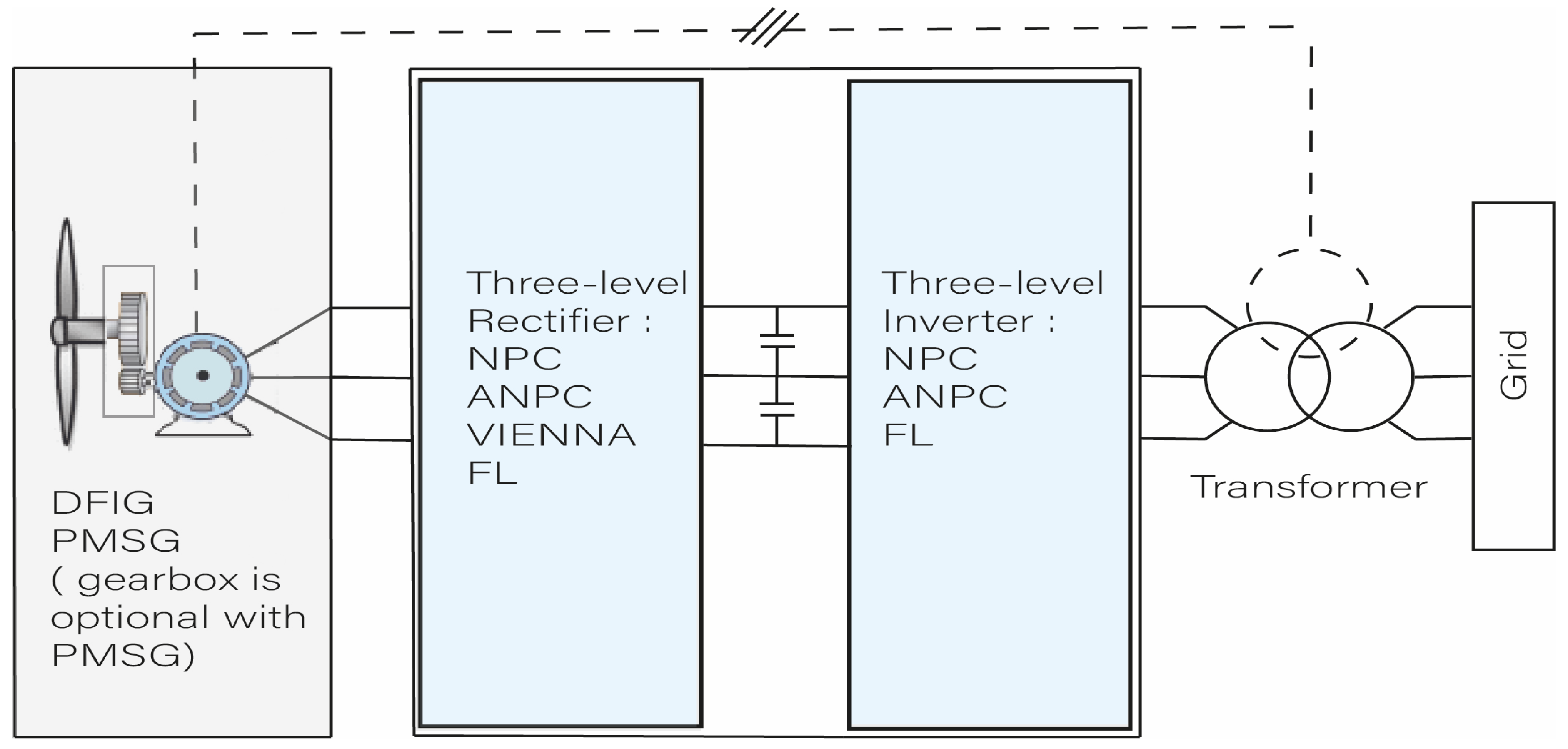
The global awareness of the dangers and risks of warming on the environment and the repercussions of its effects on humanity pushes many countries in the world to set goals and carry out environmental policies in order to reduce emissions of greenhouse gas. One of the most polluting domains today is the production of energy, hence the urgent need to change the method of energy production for more environmentally friendly production processes. As a result, the production of energy through non-polluting and renewable processes has increased considerably. Wind energy is the second most prevalent renewable energy type installed in the world, with 733 GW, which represents 26% of the global renewable electricity production [1], and the substantial investments in offshore wind turbines would allow competitive production costs and a significant increase in the installed capacity in the future [2]. Wind power conversion systems have seen continuous improvements over the past decades in terms of the drive system that changes from a semi-variable speed wind system based on the doubly fed induction generators (DIFG) to the direct drive full variable speed based on permanent magnet synchronous generator (PMSG), which represents the majority of the recent commercial systems produced by the manufacturers [3]. In order to improve the efficiency, reliability, and capacity of its energy conversion systems, several power converter topologies based on classic two-level VSI converters [4] or the three-level converters, as illustrated in Figure 1, can be used.
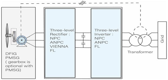
Figure 1.
Wind turbine system configuration based on DFIG or PMSG.
A neutral point clamped (NPC) converter, active neutral point clamped (ANPC) converter, and flying capacitor (FC) converter allow the transmission of powers of several megawatts, which is interesting considering the exponential increase in the power of wind turbines. In the category of interesting multilevel converters for wind power applications, Vienna converters may be a solution in the near future. They are generally known in the context of and used in high frequency switching applications, especially in telecommunications devices. Vienna unidirectional rectifiers contain a lower number of switches than the large number presented in other multi-level converter topologies. They have a low harmonic rate, high efficiency, and high power density.
Academics and the industry have expressed interest in using Vienna rectifiers in wind power systems. Different control strategies are proposed. Most of the control methods for the Vienna converters are based on the current hysteresis control. This method is developed in Refs. [5,6,7,8]. However, this method works with a variable switching frequency, which leads to an over sizing of the passive elements and variable switching losses. Vector control based on integrator and proportional controllers is also used in Refs. [9,10,11,12,13]. Direct torque control (DTC) is used for Vienna converters control in Ref. [14]. In Ref. [15], a predictive control method associated with space vector modulation (SVM) control is used for PMSG machine control. Recently, for its dynamic’s response and the performance, the model predictive control (MPC) method was introduced in Vienna rectifiers piloting [16,17,18,19]. There are a few papers in the literature using the Vienna rectifier in wind power generation systems. In Ref. [11], a Vienna rectifier is used to interface a PMSG synchronous generator with the classic vector control to do behavior study through the simulations and experiment tests. Further, Ref. [11] presents an induced voltage sensing scheme to ensure an accurate synchronization for the stator current with the induced voltage. In Ref. [20], an evaluation of the use of the Vienna rectifier in a 5MW wind power turbine is presented, and the results are compared with the performance of the diode rectifier and the conventional two-level IGBT rectifier. In Ref. [21], a vector control is developed for a wind energy conversion system based on a PMSG generator, and a Vienna rectifier is used to ensure the maximum power point tracking (MPPT) from the wind turbine. A three-level neutral point clamped (NPC) inverter is proposed as an inverter in grid-side. Further, Ref. [22] presents the development and implementation of a predictive based direct torque control of the PMSG generator using a Vienna rectifier. In Refs. [16,18], a predictive-based control is used in a wind energy production system based on the synchronous generator. In Ref. [14], a Vienna rectifier is used as the generator side converter in a wind power conversion system based on the PMSG generator direct torque control (DTC) with experimental tests.
In this paper, the Vienna rectifier vector-based control of a PMSG synchronous machine used in a direct-drive system of wind power generation is proposed. The vector control is known by its robustness and its stability. The main objective of this work is to evaluate the performance of the vector control in a Vienna rectifier-PMSG system. In contrast to the previously mentioned works, in this paper, the evaluation is carried out according to a variable wind profile to get closer to the real operating conditions of the wind turbine. This work is intended to be among the works of the scientific exploration of the efficiency and feasibility of a wind power system based on a Vienna rectifier.
The paper is organized as follows: in Section 2, the Vienna converter model, its operating principle, and the used control method are developed. In Section 3, the simulation conditions, the outcomes, and their discussions are detailed. In Section 4, the test bench developed in the laboratory, the experimental results, and their analysis are presented. The conclusions are presented in Section 5.
2. PMSG and Vienna Rectifier Models and MPPT Control Strategy
2.1. PMSG and Vienna Rectifier Models
The configuration of Vienna rectifier-based PMSG control is presented in Figure 2. This wind energy conversion system includes several parts: the wind turbine, which transforms the wind power into mechanical power, the PMSG generator, which converts the mechanical power into electric power, the Vienna converter part, which allows controlling the electric power, and the DC-bus capacitors, which ensure the DC-bus voltage stability.
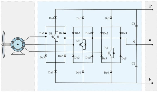
Figure 2.
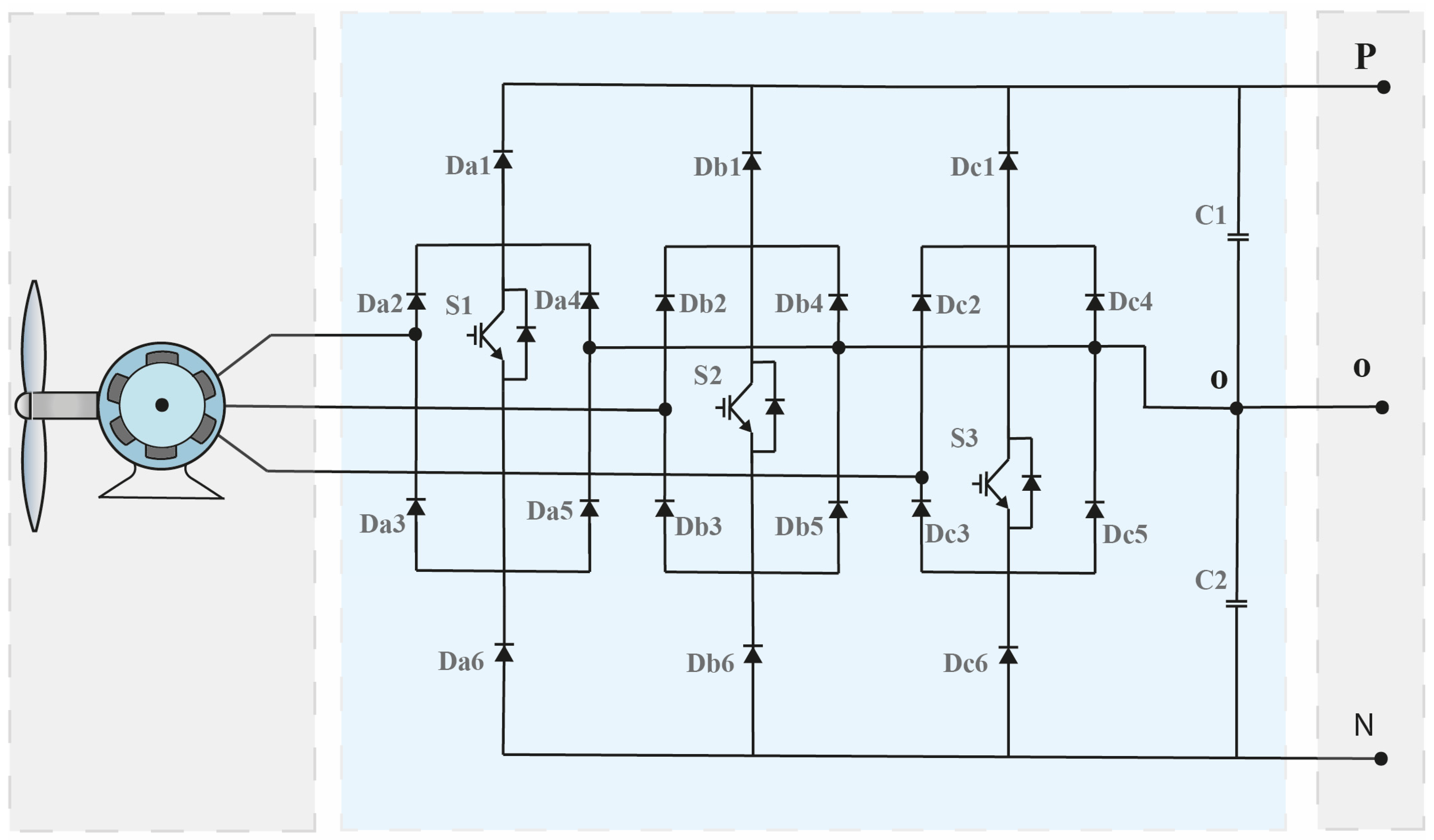
Vienna rectifier based on PMSG wind turbine applications.
Mathematical model of the PMSG generator can be expressed as a voltage equation in the three-phase a-b-c reference system [11]. Referring to the equivalent model of the PMSG presented in Figure 3, the mathematical model of the PMSG is given in Equation (1), where is the inductance in the stator, is the mutual inductance of the stator windings, is the resistance in stator.
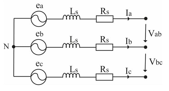
Figure 3.
Simplified model of PMSG.
The wind power, Pw, captured from a wind turbine depends on wind speed, air density, and rotor swept area [11,12,13]. Pw can be computed using Equation (2), where
is the air density, is the rotor swept area, and is the wind speed.
The PMSG model in the d-q reference frame is given in Equation (3), where and are the d-q voltages, and are the d-q currents, is the flux of the permanent magnet, is the rotor speed.
The torque equation of PMSG is given in Equation (4), where is the number of the pole pairs.
2.2. Vienna Rectifier Operation Principle
A Vienna rectifier has several advantages, such as: the attractive price due to the limited number of switches in its configuration, energy quality due to the low rate of harmonic, and high efficiency. The control of switching state of the transistors and, depending on the polarities of the phase currents at the input of the rectifier, the DC-bus voltage at the terminals of the rectifier output can be controlled at different values. Vienna rectifier switching states are presented in Table 1.

Table 1.
Vienna converter switching states.
The principle of operation of phase A of the converter is illustrated in Figure 4. The operations of phases B and C are the same to that of phase A. In the case where the polarity of phase A is positive and switch S1 is OFF, as presented in Figure 4a, the current flows through diodes Da1 and Da2 and phase A is, therefore, connected to the positive point of the DC-bus, and the voltage to the output of the rectifier is Vdc/2. In the case where the polarity of phase A is negative and switch S1 is OFF, as presented in Figure 4b, the current flows through the diodes Da3 and Da6 and phase A is, therefore, connected to the negative point of the DC-bus, and the voltage to the output of the rectifier is −Vdc/2. In the case where the polarity of phase A is positive and switch S1 is ON, as presented in Figure 4c, the current flows through the diodes Da2, Da5 and switch S1, phase A is, therefore, connected to the neutral point of the DC-bus, and the voltage at the output of the rectifier is 0. In the case that the polarity of phase A is negative and switch S1 is ON, as illustrated in Figure 4d, the current flows through the diodes Da3, Da4, and switch S1, phase A is, therefore, connected to neutral point of the DC-bus, and the rectifier output voltage is 0.
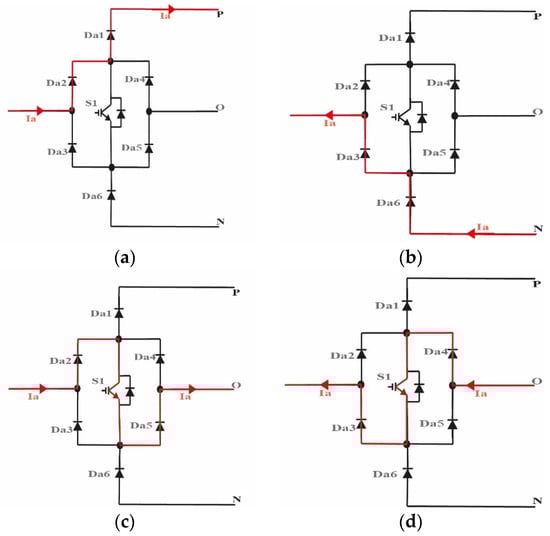
Figure 4.
Vienna rectifier operation principle. (a) When S1 is OFF and Ia > 0 (b) When S1 is OFF and Ia < 0 (c) When S1 is ON and Ia > 0 (d) When S1 is ON and Ia < 0.
2.3. Control Strategy
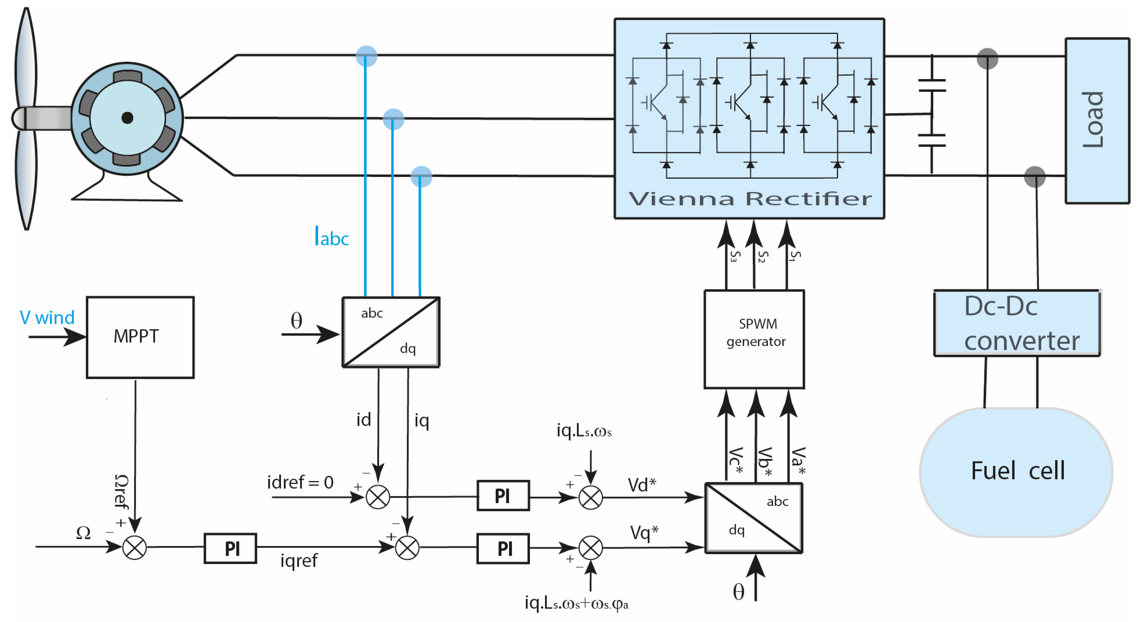
The used control for a wind power system is generally based on the MPPT technique [23], which ensures the extraction of the maximum power from the wind turbine, as shown in Figure 5. However, this paper focuses on the control of Vienna converters and the satisfaction of a variable load demand, so the reference of iq is obtained according to the demand of the load. The control of the generator is carried out via a vector control using PI correctors for and currents control. The model of the PMSG machine after Laplace transformation is presented in Equation (5).

Figure 5.
Vienna rectifier control strategy-based MPPT technique for wind turbine applications.
The vector control strategy applied in this study serves to impose a reference for the d-axis current equal to zero. This control strategy allows reducing the conduction losses based on Joule’s effect. In order to obtain the smallest static error, to ensure stability, and reject the disturbances, the values of the PI correctors are computed using Equation (6).
3. Simulations Conditions and Results
3.1. Simulations Conditions
The simulations are completed using MATLAB/Simulink. The synchronous machine is driven at a variable speed according to a variable wind speed profile applied to the turbine. The DC-bus voltage is controlled at 400 V through the basic DC/DC-based boost converter linked to the fuel cell. The fuel cell model used is detailed in Ref. [24]. The configuration of the simulated system is the same as in Figure 5. The sampling period Ts is 5 µs. The used load in the DC-bus is a resistance of 100 Ω. The parameters of the PMSG and the wind turbine used in the simulations are shown in Table 2. The objective is to verify the reaction in both cases: in the steady state operation in the first part of the simulation results and in transient mode operation in the second part. The conventional control principle is used for PMSG piloting. The reference current, idref, is set to zero, and the control is ensured via the Iqref reference current, which is considered as a variable reference.
Table 2.
Parameters of the PMSG and wind turbine control.
3.2. Simulations Results
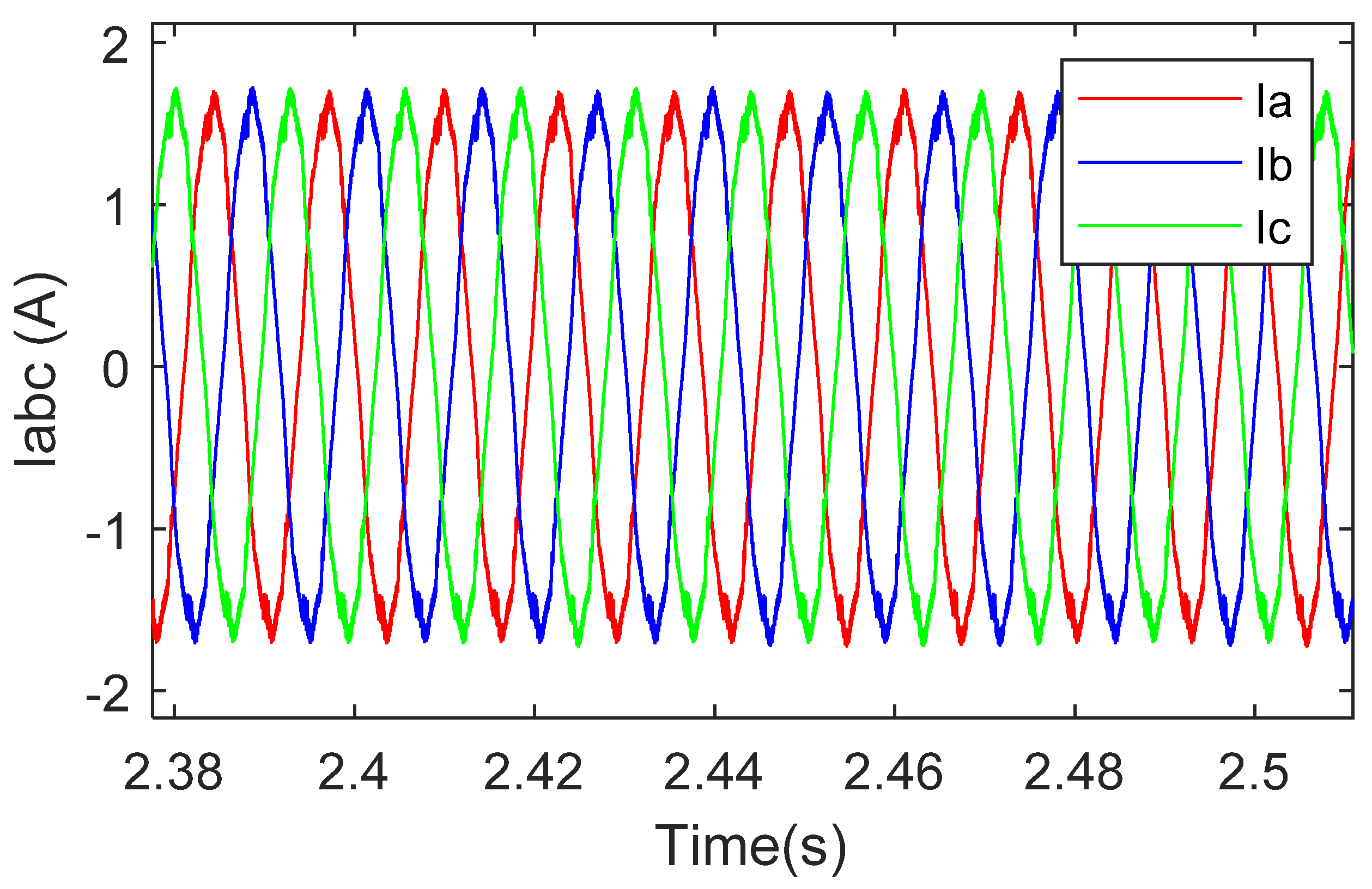
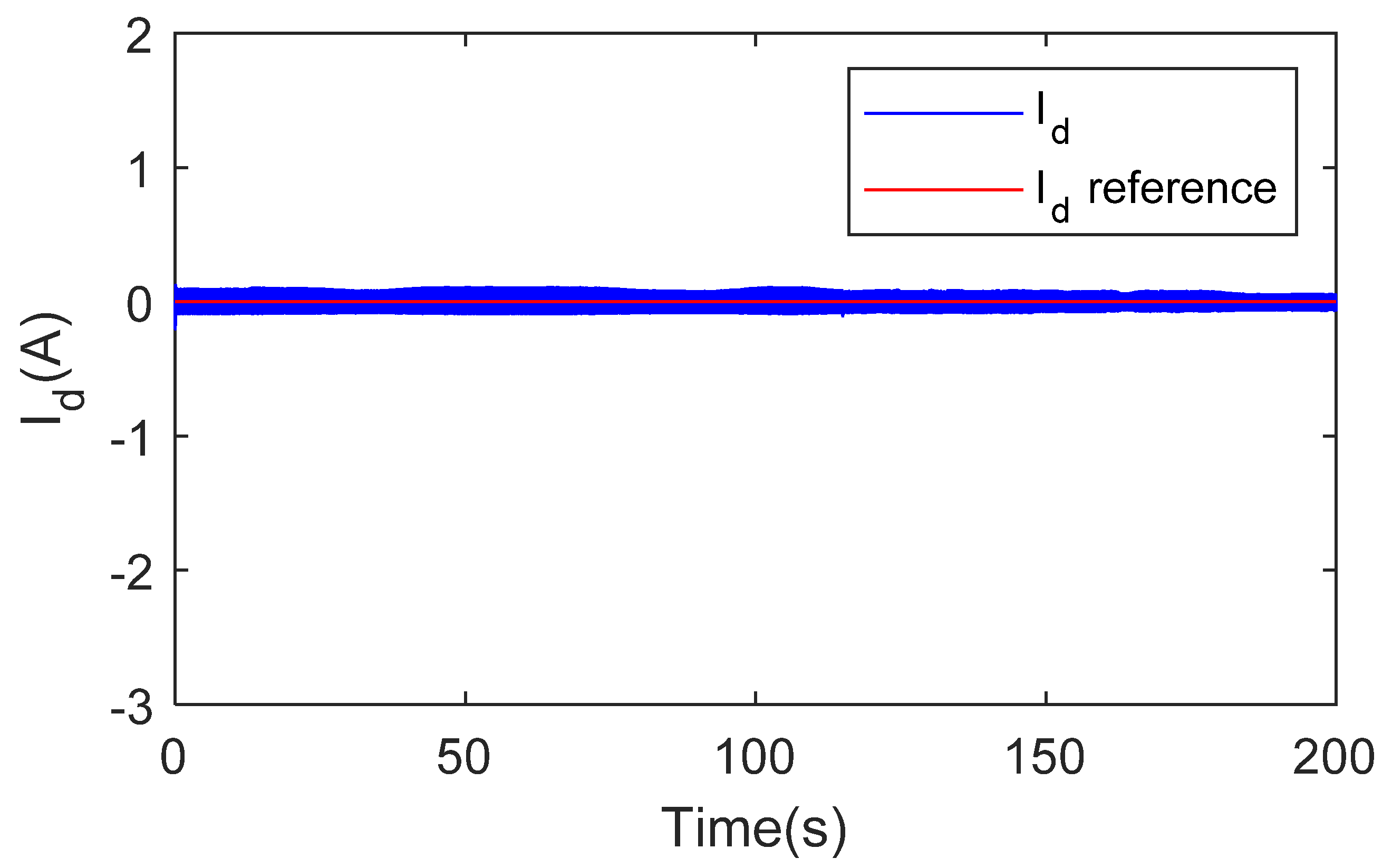
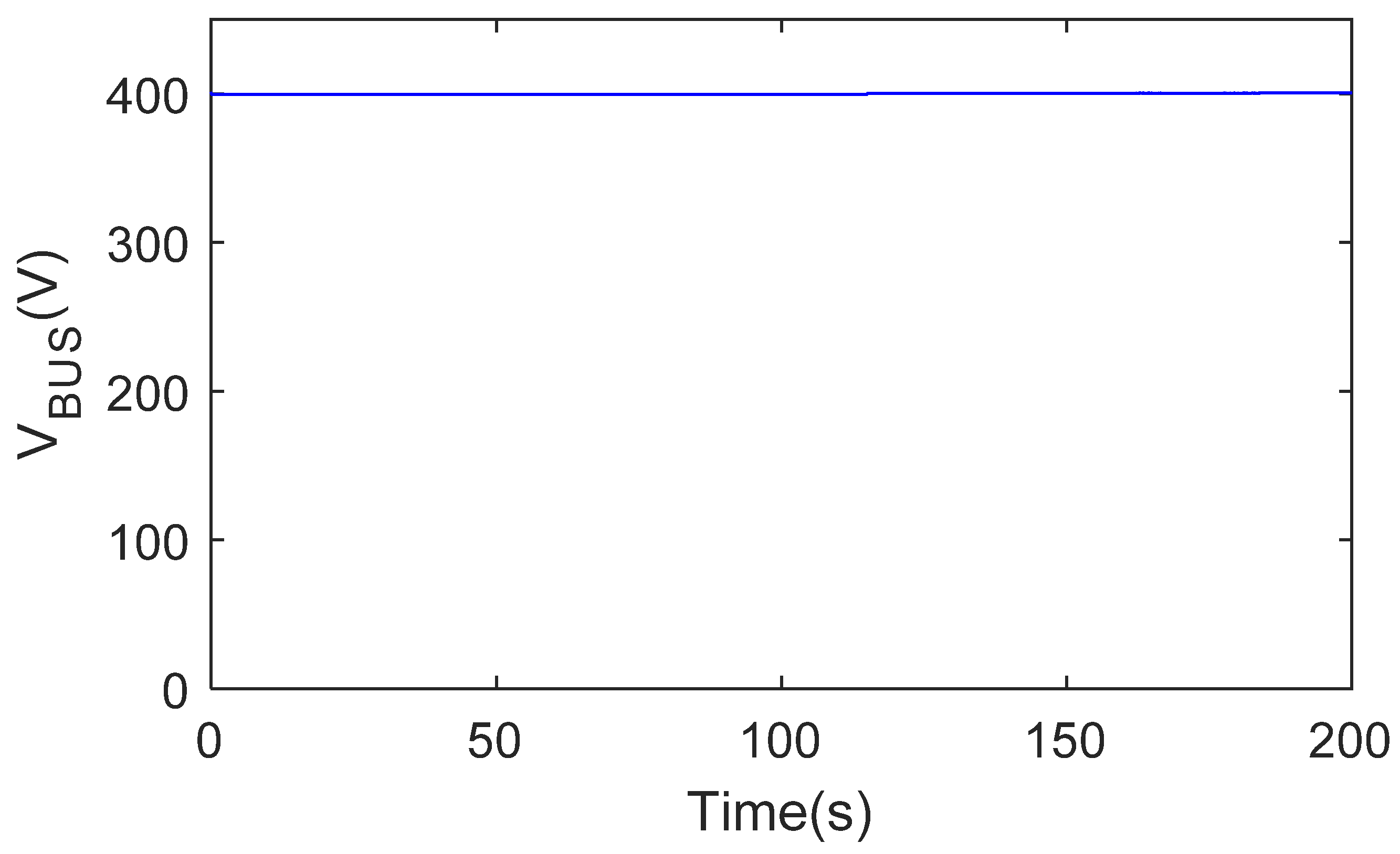
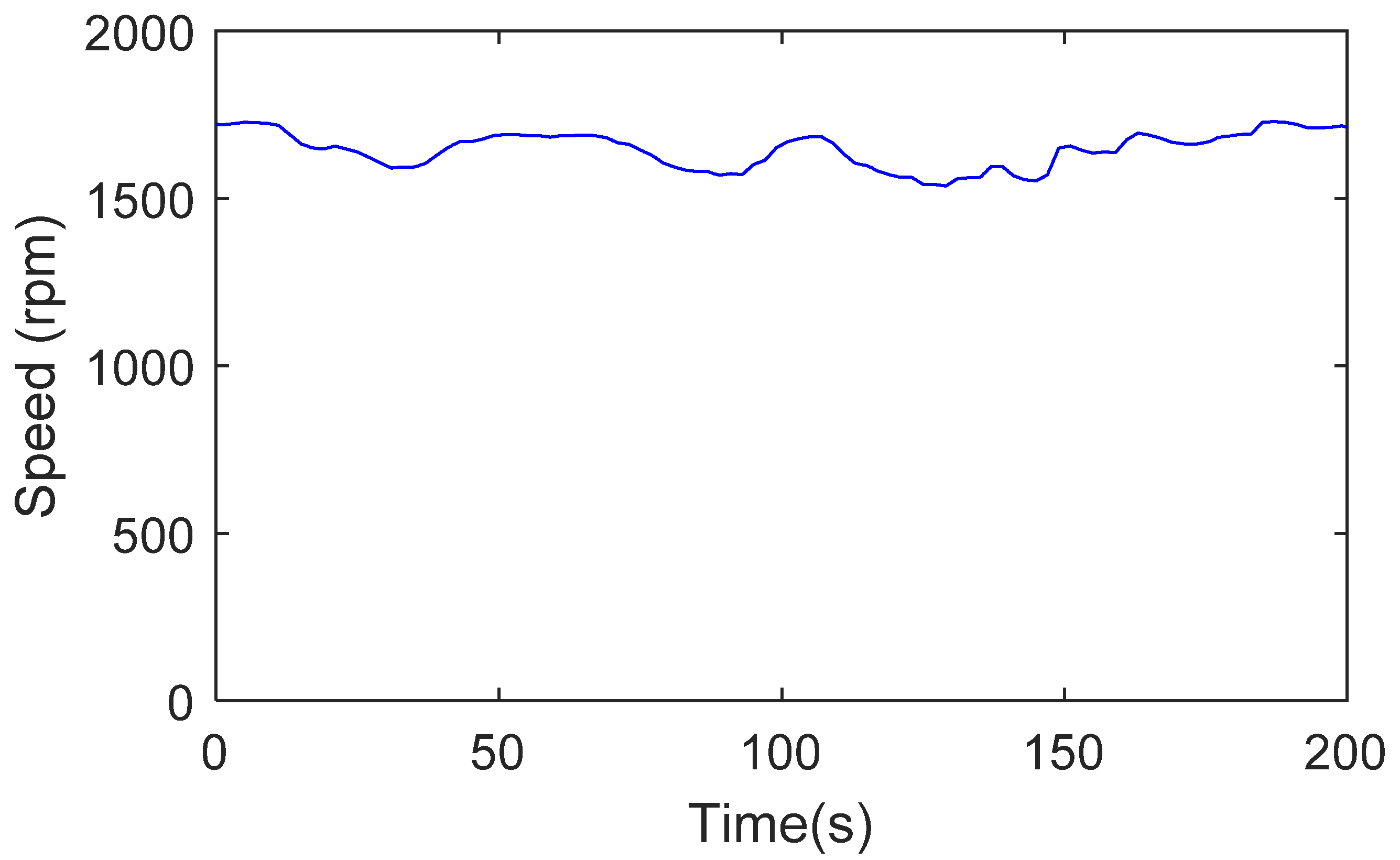
Figure 6 shows the three-phase currents at the input of the Vienna rectifier in steady state operation; the three-phase currents are sinusoidal and balanced. Figure 7 shows the curves of the currents over the transition period. This figure shows the dynamics response of the system when changing the current reference at t = 120 s. Figure 8 and Figure 9 show the stator currents in the dq reference frame. These curves, taken under transient operation, show that the performance of the control loops of the two currents (id and iq) are satisfactory; i.e., the id current follows its reference fixed to 0, the iqref reference changes during the simulations from 1A to 2A, and the iq current follows the reference perfectly with an interesting dynamic during the transient phase. The DC-bus voltage, as shown in Figure 10, remains constant despite changes in the current reference supplied by the synchronous generator. Figure 11 shows the speed of the PMSG; the variations in the speed over time are in the image of the imposed wind profile to the turbine, which brings us closer to the real operating conditions of wind turbines.
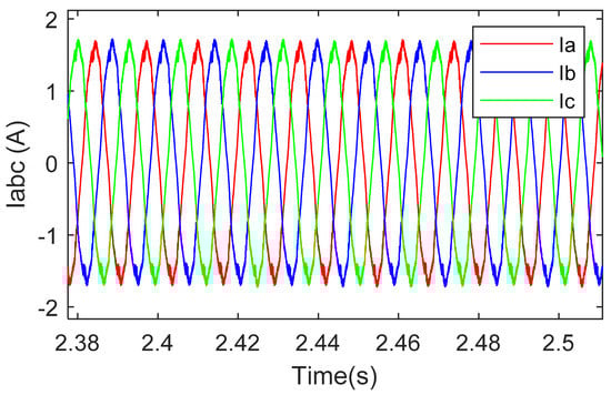
Figure 6.
Zoom in three-phase stator currents.
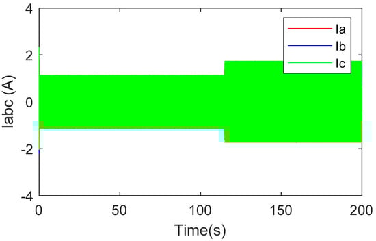
Figure 7.
Three-phase PMSG currents with variable reference.
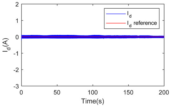
Figure 8.
id current control result.
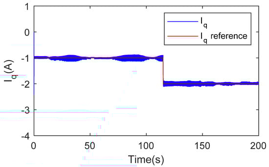
Figure 9.
iq current control result.
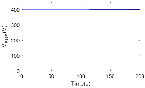
Figure 10.
DC-bus voltage.
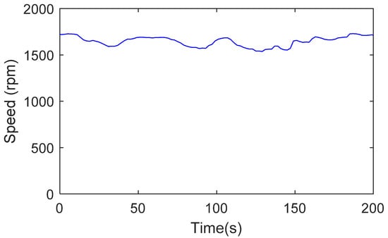
Figure 11.
PMSG variable speed obtained by simulation.
4. Experimental Tests and Results
4.1. Experimental Setup
In order to validate experimentally the control method based on the current control for a Vienna rectifier, a laboratory test bench is carried out. This tests bench is presented in Figure 12. It includes a wind turbine behavior emulator based on the DC motor (1) associated to DC power supply (2) and a DC/DC converter. The DC motor is mechanically coupled to a 1.7 kW PMSG generator (3). The output of the PMSG is connected to a Vienna rectifier with three IGBT modules and their three associated drivers (4); the control unit based on a PC system (5) and a dSPACE system (6) and the data acquisition system are ensured by a set of sensors (7), which allows to control and visualize the different variables of the system in real-time operation. The parameters of the DC motor are shown in Table 3, and those of PMSG are given in Table 2.
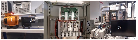
Figure 12.
The test bench platform.
Table 3.
Parameters of DC motor.
4.2. Experimental Results and Discussion
In this part, the results of the experimental tests are presented. The used parameters in the system control are shown in Table 2. DC-bus voltage reference is fixed to 400V using a fuel cell emulator based on controlled DC-source. The power transmitted to the DC load is controlled via the current control supplied by the generator.
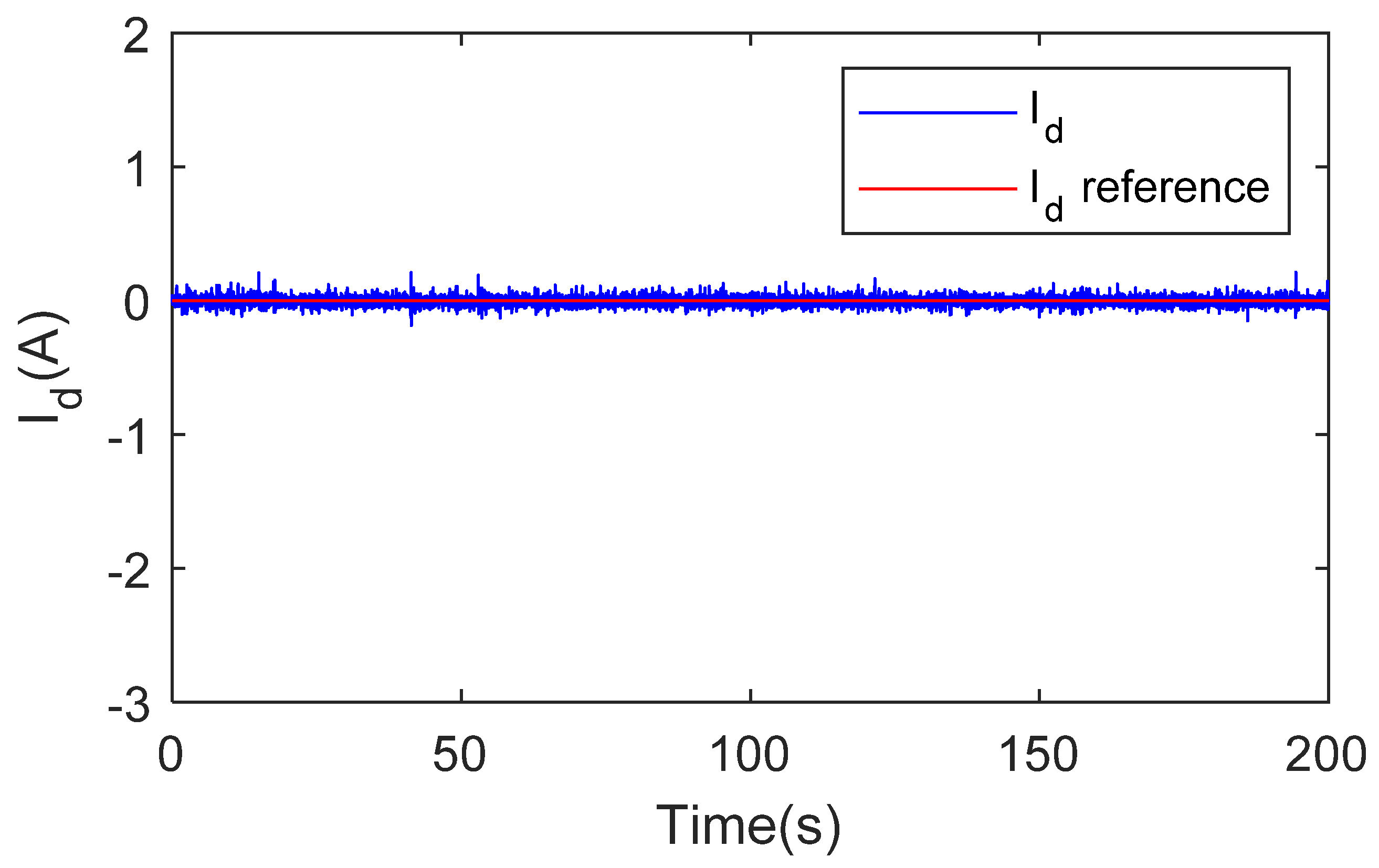
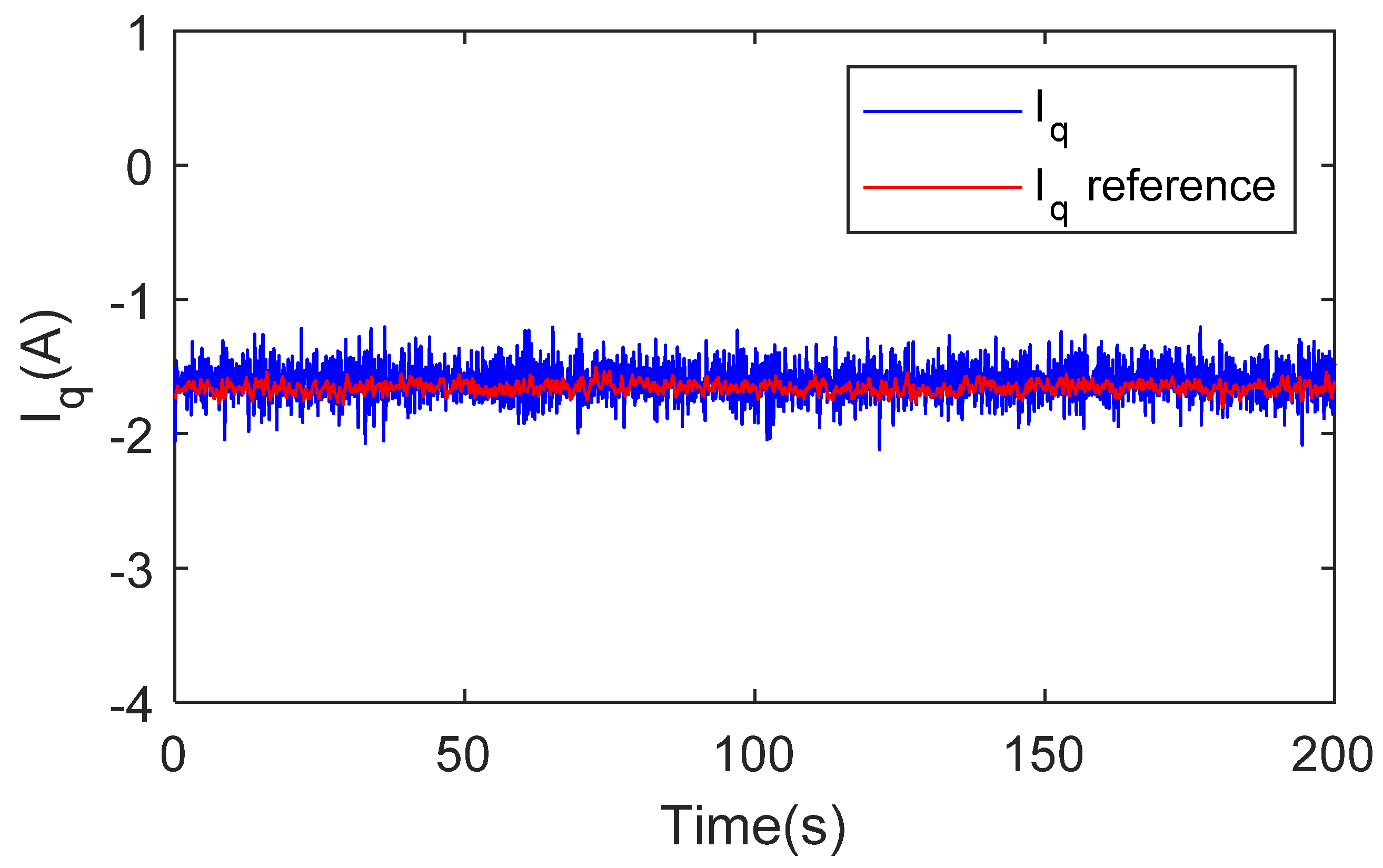
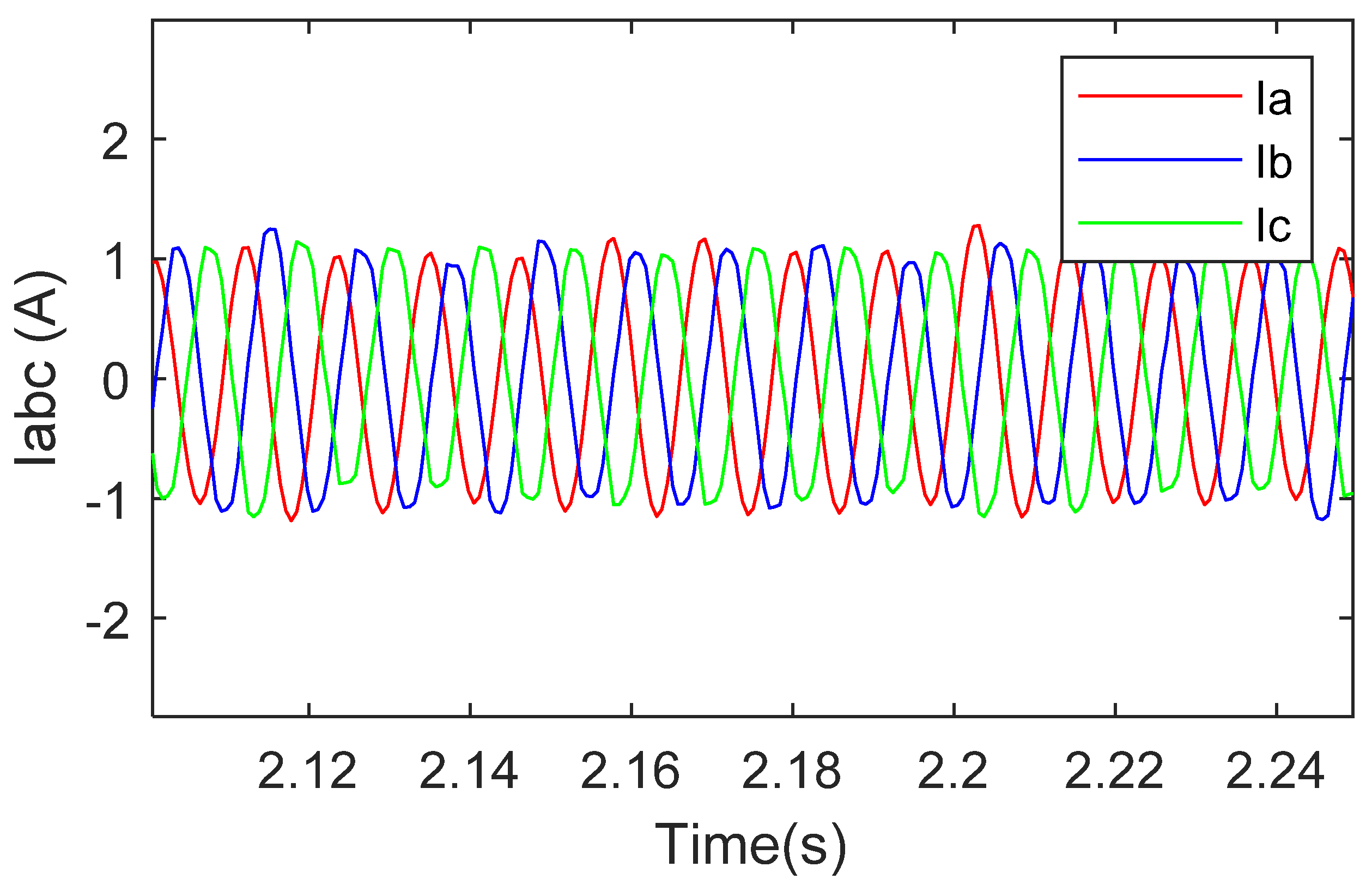
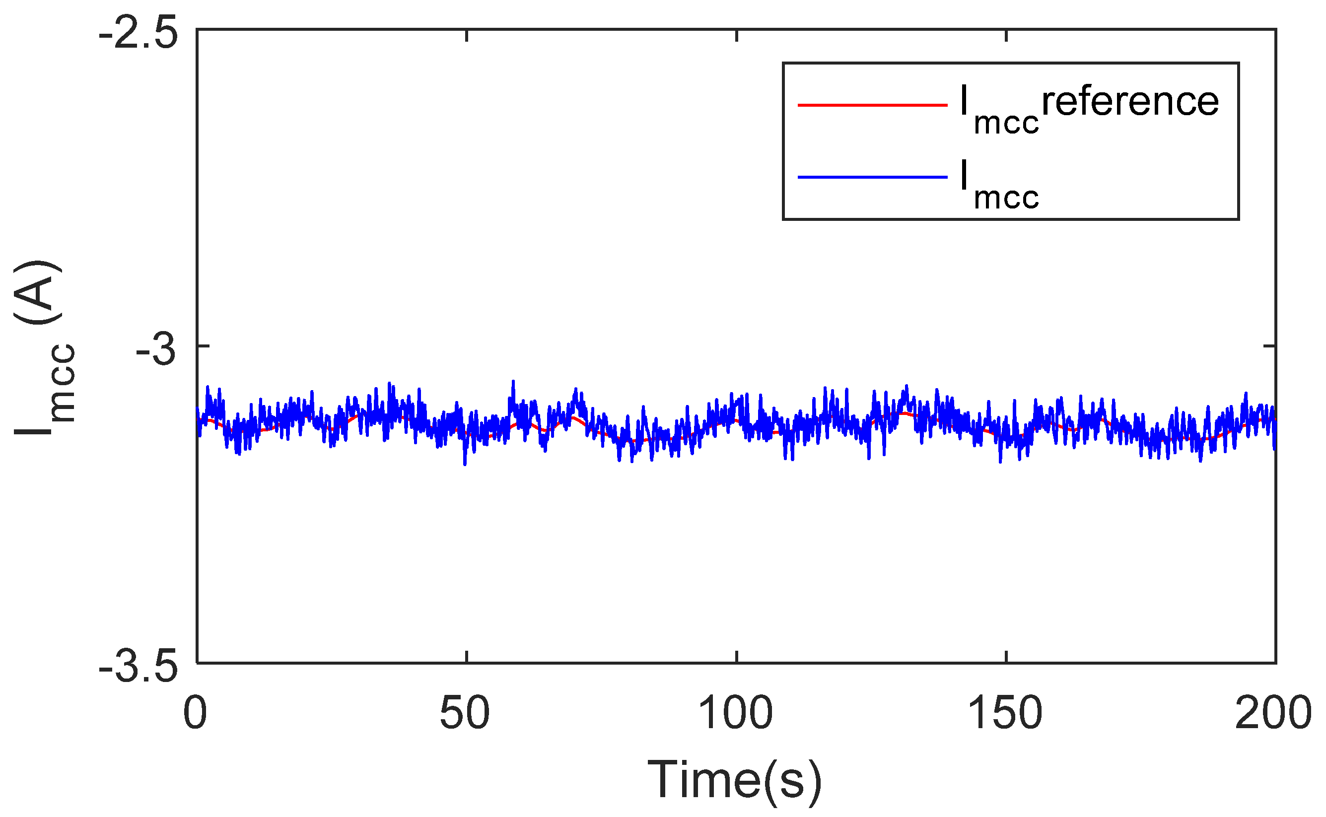
Figure 13 illustrates the id current control result where it can be seen that it follows the imposed reference fixed to 0. Figure 14 shows the iq current control result, which presents a good concordance with its reference. Figure 15 shows the three-phase currents at the out of the PMSG. Figure 16 shows the current control result of the DC motor used to emulate the wind turbine behavior.
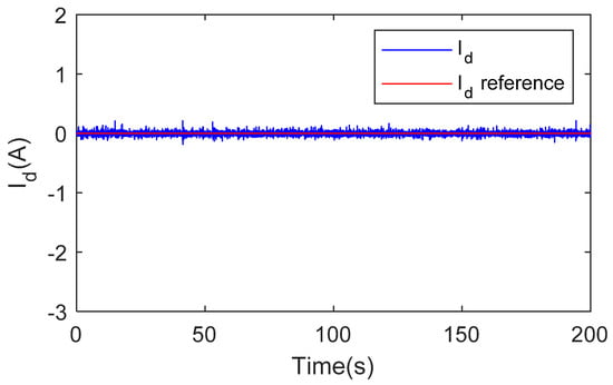
Figure 13.
id current control result with a constant reference.
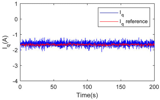
Figure 14.
iq current control result with a constant reference.
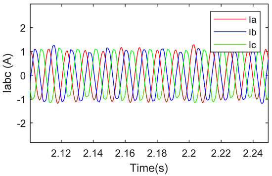
Figure 15.
Zoom of the three-phase stator currents.
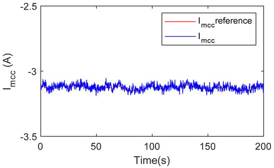
Figure 16.
DC motor current control result used to emulate the wind turbine.
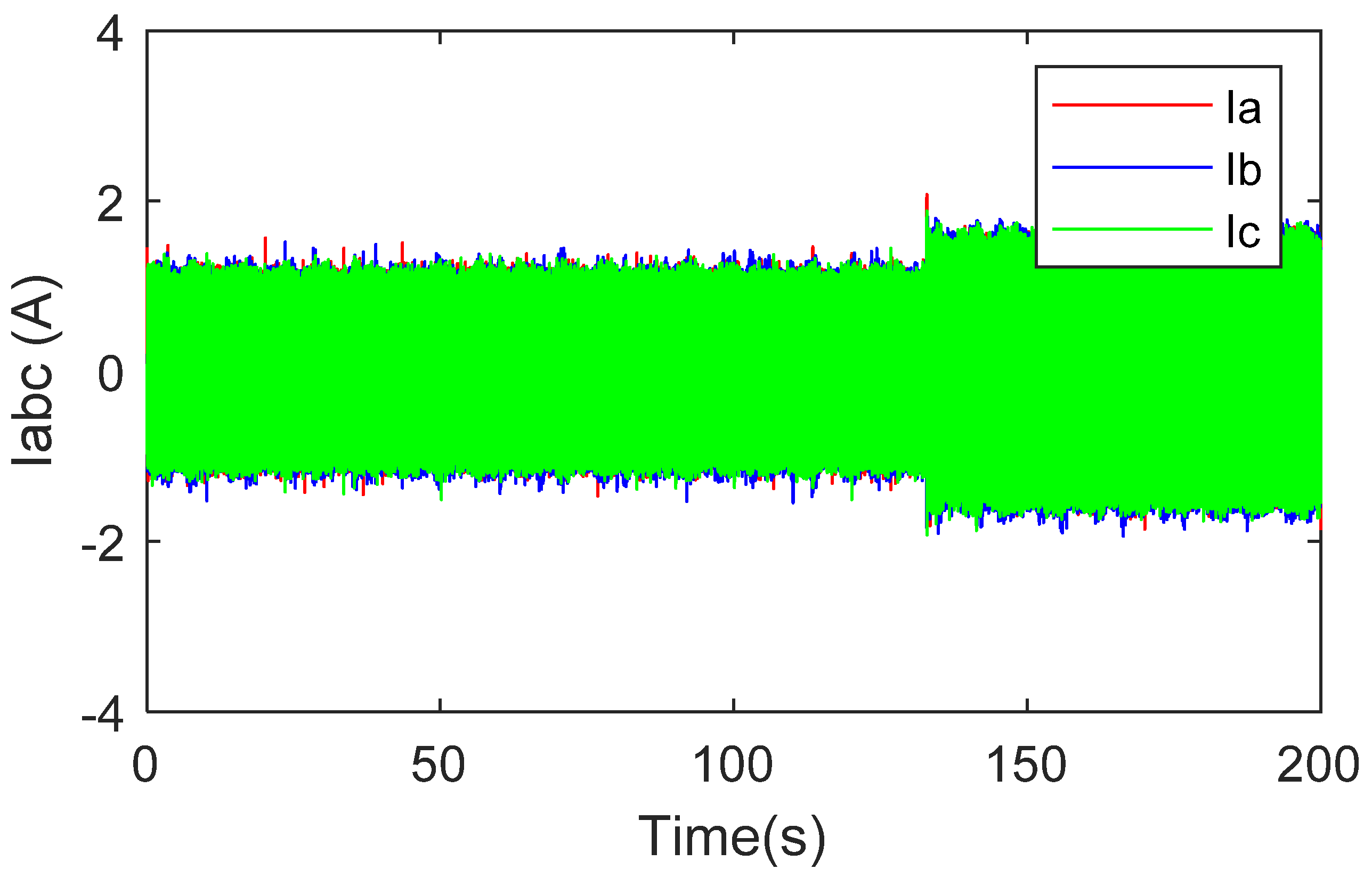
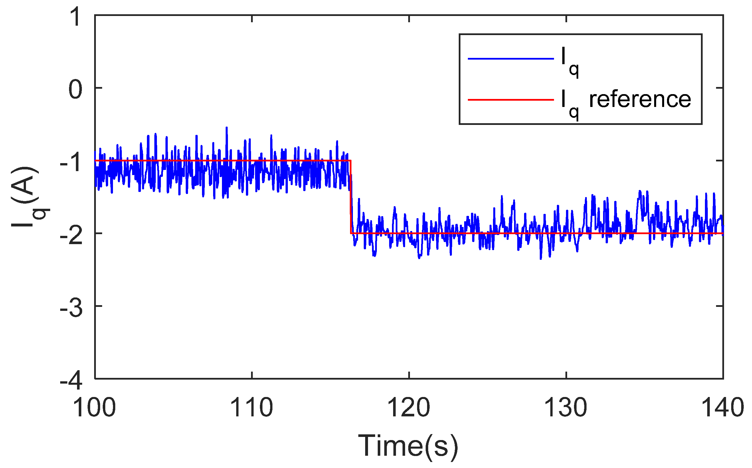
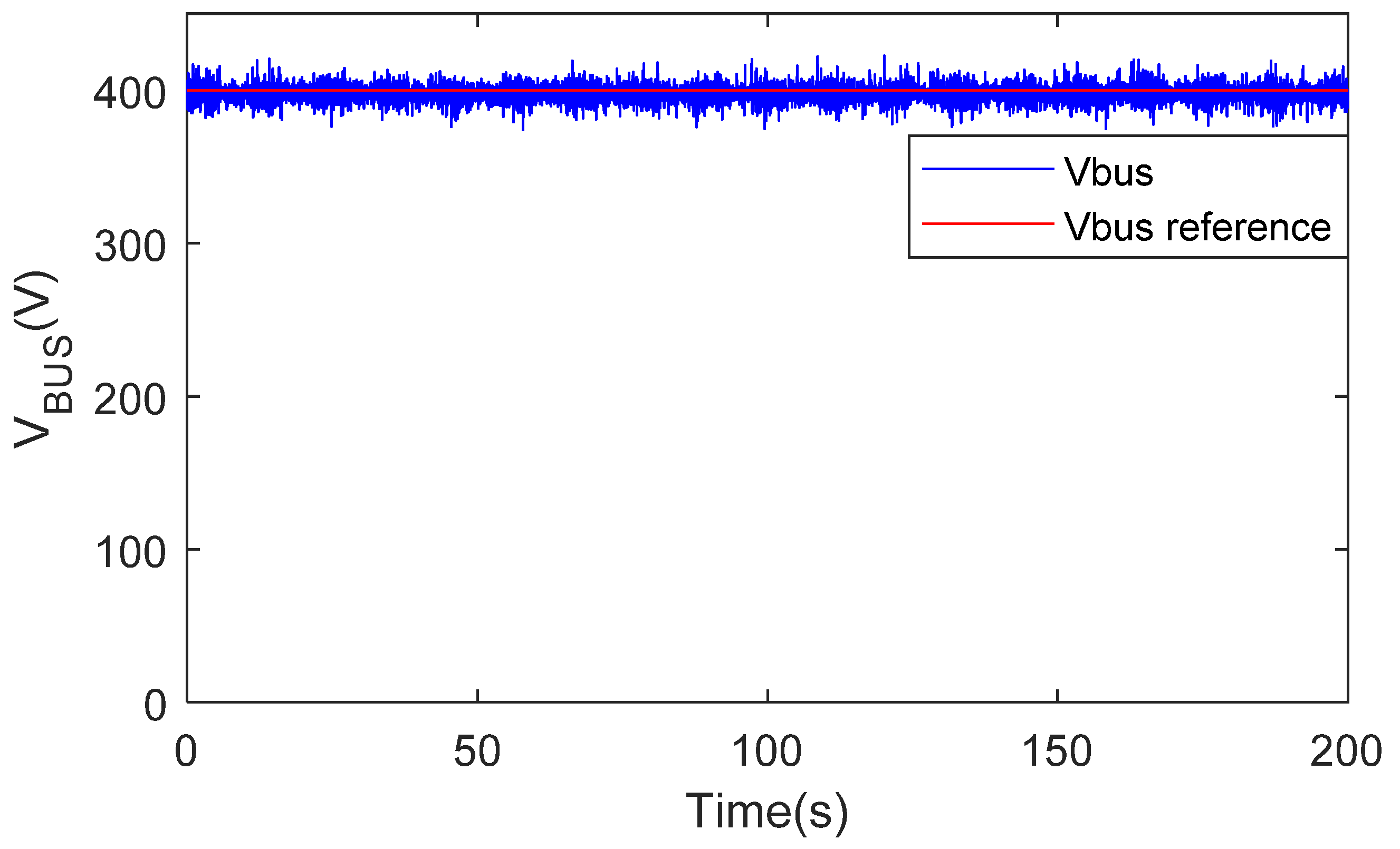
The following results are obtained with variable wind speed conditions. The aim of these tests is to see the reaction of the system during a variable demand of the load. The id current reference remains constant and zero. Figure 17 shows the measured currents in the PMSG over the transition period. This figure shows the dynamic response of the experimental system when the load demand is changing. Figure 18 illustrates the response of the system when a variable reference is applied for iq current, where the dynamics response of the system is always satisfactory. The DC-bus voltage, as shown in Figure 19, is regulated to a constant value of 400V, and it pursues its reference despite the changes in the current reference of the synchronous generator. Figure 20 shows the curve of the speed of the PMSG obtained from the experimental tests. We notice the variations in the speed due to the drive of the PMSG by a DC motor to approach the real conditions of operation of the wind turbines and to have the results closer to reality.

Figure 17.
Three-phase PMSG currents with variable load demand.

Figure 18.
iq current control result with a variable reference.
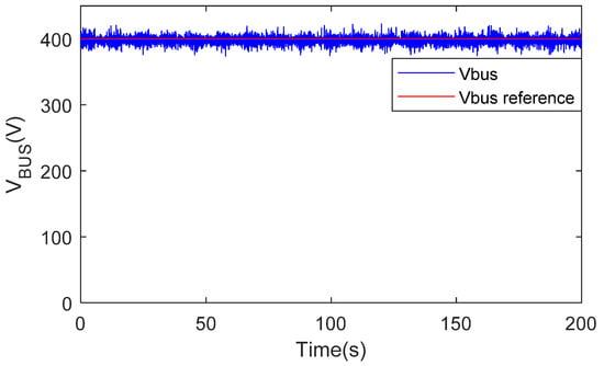
Figure 19.
DC-bus voltage control result with the reference of 400 V.
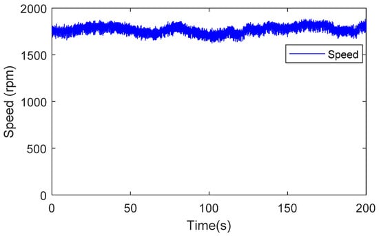
Figure 20.
PMSG speed experimentation result.
The control strategy of Vienna converters in a wind power system is verified by simulation and experimentation. The results of the experimentation confirm the results obtained in the simulations. The curves from the simulations and experimental tests for the controlled id current are identical and follow their references. For the iq current, we notice more remarkable fluctuations in the curve obtained from the experiment; this is due to the sensitivity of the used devices. In both cases, the iq current follows its variable reference, iqref, with an interesting dynamic. The control of the DC-bus based on the fuel cell emulator is stable and efficient in the simulations and experimentation despite the change of the imposing reference. In addition to the simplicity of the method, the results in terms of dynamics and stability of response give interesting performances.
5. Conclusions
This paper presents a study of a wind power conversion based on a Vienna rectifier. The use of this type of converter in wind power systems has several advantages, such as: the power density of the converters, small size for very high power, reliability of the system, and limited number of power switches, which are the main cause of faults in the converters used in wind turbines. A PMSG vector control was used in this study, the controlled system was subjected to operating conditions closest to a wind system, a variable speed according to a wind speed profile was used, and a variable load demand was also applied. Its performance and efficiency were evaluated through the simulations. The results of the control loops present a response with satisfactory dynamic performances. To emulate the operation of the wind turbine and verify the performance of the developed control, a laboratory test bench was completed. The control algorithm was implemented in a real-time dSPACE card. The obtained results during the experimental tests were presented and analyzed. They show the effectiveness of the proposed approach, particularly in terms of the dynamic response and simplicity of the implementation of the method.
Author Contributions
Conceptualization, A.A. and M.B.C.; methodology, A.A. and M.B.C.; software, A.A., M.B.C. and B.D.; validation, A.A., M.B.C. and B.D.; formal analysis, A.A. and M.B.C.; investigation, A.A. and M.B.C.; data curation, A.A. and M.B.C.; writing—original draft preparation, A.A. and B.D.; writing—review and editing, A.A., M.B.C. and B.D.; visualization, A.A. and M.B.C.; supervision, M.B.C. and B.D.; project administration, M.B.C. and B.D.; funding acquisition, M.B.C. and B.D. All authors have read and agreed to the published version of the manuscript.
Funding
This research received no external funding.
Institutional Review Board Statement
Not applicable.
Informed Consent Statement
Not applicable.
Data Availability Statement
The data presented in this study are available on request from the corresponding authors.
Acknowledgments
This work was supported by the University of Le Havre Normandy and the Normandy region in France.
Conflicts of Interest
The authors declare no conflict of interest.
Nomenclature
| Pn | PMSG rated power |
| Pw | The power captured by wind turbine |
| Rt | Radius of the wind turbine |
| Rs | PMSG resistance |
| Ls | Inductance of the PMSG |
| The mutual inductance of the stator windings | |
| The number of the PMSG pole pairs | |
| J = Jg + Jt | Moment of inertia of the PMSG and turbine (DC motor) |
| Air density | |
| Rotor swept area | |
| Wind speed | |
| Vbus | DC-bus voltage |
| d-q voltages | |
| , | d-q currents |
| Dynamic of the current loop | |
| C1, C2 | DC-bus capacitor |
| Magnetic induced flux |
References
- Alili, A.; Camara, M.B.; Dakyo, B.; Raharijaona, J. Power Electronic Converters Review for Wind Turbine Applications: State of Art, Reliability and Trends. In Proceedings of the GREEN 2020 Conference, IARIA, Valencia, Spain, 21–25 November 2020; pp. 12–18. Available online: https://www.thinkmind.org/index.php?view=article&articleid=green_2020_1_30_80025 (accessed on 15 February 2022).
- Gao, Z.; Liu, X. An Overview on Fault Diagnosis, Prognosis and Resilient Control for Wind Turbine Systems. Processes 2021, 9, 300. [Google Scholar] [CrossRef]
- Yaramasu, V.; Wu, B.; Sen, P.C.; Kouro, S.; Narimani, M. High-power wind energy conversion systems: State-of-the-art and emerging technologies. Proc. IEEE 2015, 103, 740–788. [Google Scholar] [CrossRef]
- Jiang, Y.; Jin, X.; Wang, H.; Fu, Y.; Ge, W.; Yang, B.; Yu, T. Optimal Nonlinear Adaptive Control for Voltage Source Converters via Memetic Salp Swarm Algorithm: Design and Hardware Implementation. Processes 2019, 7, 490. [Google Scholar] [CrossRef] [Green Version]
- Minibock, J.; Stogerer, F.; Kolar, J. A novel concept for mains voltage proportional input current shaping of a vienna rectifier eliminating controller multipliers. i. basic theoretical considerations and experimental verification. In Applied Power Electronics Conference and Exposition 2001, APEC 2001. Sixt. Annu. IEEE 2001, 1, 582–586. [Google Scholar] [CrossRef]
- Soeiro, T.; Kolar, J. Analysis of high-efficiency three-phase two- and three-level unidirectional hybrid rectifiers. IEEE Trans. Ind. Electron. 2013, 60, 3589–3601. [Google Scholar] [CrossRef]
- Kolar, J.; Zach, F.C. A novel three-phase utility interface minimizing line current harmonics of high-power telecommunications rectifier modules. IEEE Trans. Ind. Electron. 1997, 44, 456–467. [Google Scholar] [CrossRef] [Green Version]
- Friedli, T.; Hartmann, M.; Kolar, J. The essence of three-phase pfc rectifier systems 2014; part ii. IEEE Trans. Ind. Electron. 2014, 29, 543–560. [Google Scholar] [CrossRef]
- Bel Haj Youssef, N.; Al-Haddad, K.; Kanaan, H. Large-signal modeling and steady-state analysis of a 1.5-kw three-phase/switch/level (vienna) rectifier with experimental validation. IEEE Trans. Ind. Electron. 2008, 55, 1213–1224. [Google Scholar] [CrossRef]
- Ide, P.; Schafmeister, F.; Frohleke, N.; Grotstollen, H. Enhanced control scheme for three-phase three-level rectifiers at partial load. IEEE Trans. Ind. Electron. 2005, 52, 719–726. [Google Scholar] [CrossRef]
- Zhao, H.; Zheng, T.Q.; Li, Y.; Du, J.; Shi, P. Control and Analysis of Vienna Rectifier Used as the Generator-Side Converter of PMSG-based Wind Power Generation Systems. J. Power Electron. 2017, 17, 212–221. [Google Scholar] [CrossRef] [Green Version]
- Dalessandro, L.; Round, S.D.; Drofenik, U.; Kolar, J.W. Discontinuous Space-Vector Modulation for Three-Level PWM Rectifiers. IEEE Trans. Power Electron. 2008, 23, 530–542. [Google Scholar] [CrossRef]
- Hang, L.; Li, B.; Zhang, M.; Wang, Y.; Tolbert, L.M. Equivalence of SVM and Carrier-Based PWM in Three-Phase/Wire/Level Vienna Rectifier and Capability of Unbalanced-Load Control. IEEE Trans. Ind. Electron. 2014, 61, 20–28. [Google Scholar] [CrossRef]
- Rajaei, A.; Mohamadian, M.; Varjani, A.Y. Vienna-Rectifier-Based Direct Torque Control of PMSG for Wind Energy Application. IEEE Trans. Ind. Electron. 2013, 60, 2919–2929. [Google Scholar] [CrossRef]
- Lee, J.; Bak, Y.; Lee, K.; Blaabjerg, F. MPC-SVM method for Vienna rectifier with PMSG used in Wind Turbine Systems. In Proceedings of the 2016 IEEE Applied Power Electronics Conference and Exposition (APEC), Long Beach, CA, USA, 20–24 March 2016; pp. 3416–3421. [Google Scholar] [CrossRef]
- Lee, J.S.; Lee, K.B. Predictive control of Vienna rectifiers for PMSG systems. IEEE Trans. Ind. Electron. 2017, 64, 2580–2591. [Google Scholar] [CrossRef]
- Zhu, W.; Chen, C.; Duan, S. Model predictive control with improved discrete space vector modulation for three-level Vienna rectifier. IEEE Trans. Power Electron. 2019, 12, 1998–2004. [Google Scholar] [CrossRef]
- Lee, J.S.; Lee, K.B.; Blaabjerg, F. Predictive control with discrete space-vector modulation of Vienna rectifier for driving PMSG of wind turbine systems. IEEE Trans. Power Electron. 2019, 34, 12368–12383. [Google Scholar] [CrossRef]
- Yu, F.; Liu, X.; Zhang, X.; Zhu, Z. Model Predictive Virtual-Flux Control of Three-Phase Vienna Rectifier Without Voltage Sensors. IEEE Access 2019, 7, 169338–169349. [Google Scholar] [CrossRef]
- Nikouei, M. Design and Evaluation of the Vienna Rectifier for a 5 MW Wind Turbine System. Master’s Thesis, Chalmers University of Technology, Gothenburg, Sweden, 2013. Available online: https://publications.lib.chalmers.se/records/fulltext/184817/184817.pdf (accessed on 15 February 2022).
- Rajaei, A.; Mohamadian, M.; Dehghan, S.M.; Yazdian, A. PMSG-based variable speed wind energy conversion system using Vienna rectifier. Eur. Trans. Electr. Power 2011, 21, 954–972. [Google Scholar] [CrossRef]
- Yip, S.Y.; Che, H.S.; Tan, C.P.; Chong, W.T. A Lookup Table Model Predictive Direct Torque Control of Permanent-Magnet Synchronous Generator Based on Vienna Rectifier. IEEE J. Emerg. Sel. Top. Power Electron. 2020, 8, 1208–1222. [Google Scholar] [CrossRef]
- Pan, L.; Zhu, Z.; Xiong, Y.; Shao, J. Integral Sliding Mode Control for Maximum Power Point Tracking in DFIG Based Floating Offshore Wind Turbine and Power to Gas. Processes 2021, 9, 1016. [Google Scholar] [CrossRef]
- Oukkacha, I.; Sarr, C.T.; Camara, M.B.; Dakyo, B.; Parédé, J.Y. Energetic Performances Booster for Electric Vehicle Applications Using Transient Power Control and Supercapacitors-Batteries/Fuel Cell. Energies 2021, 14, 2251. [Google Scholar] [CrossRef]


Publisher’s Note: MDPI stays neutral with regard to jurisdictional claims in published maps and institutional affiliations. |
© 2022 by the authors. Licensee MDPI, Basel, Switzerland. This article is an open access article distributed under the terms and conditions of the Creative Commons Attribution (CC BY) license (https://creativecommons.org/licenses/by/4.0/).