Article

Battery Hybrid Energy Storage Systems for Full-Electric Marine Applications

Flanders Make, 3001 Heverlee, Belgium
*
Author to whom correspondence should be addressed.
Processes 2022, 10(11), 2418; https://doi.org/10.3390/pr10112418
Submission received: 10 October 2022 / Revised: 10 November 2022 / Accepted: 12 November 2022 / Published: 16 November 2022
(This article belongs to the Special Issue Recent Advances in Electrical Power Engineering)

Abstract

:
The high cost of Lithium-ion battery systems is one of the biggest challenges hindering the wide adoption of electric vessels. For some marine applications, battery systems based on the current monotype topologies are significantly oversized due to variable operational profiles and long lifespan requirements. This paper deals with the battery hybrid energy storage system (HESS) for an electric harbor tug to optimize the size of the battery system. The impact of battery hybridization was investigated on three key performance indicators inclusive of cost, system efficiency, and battery weight. The design life of the battery system is considered to be 10 years, and NMC and LTO cell technologies are used as high-energy (HE) and high-power (HP) battery cells. The HESS design is based on a parallel full-active architecture with a rule-based energy management strategy. The results of this research indicate that battery hybridization can reduce the system cost by around 28% and 14% in comparison with a monotype battery with LTO and NMC cells, respectively. Although no noticeable difference in system efficiency is observed between the monotype system and HESS, battery hybridization reduces the total weight of the battery cells by more than 30% compared to monotype topology. This study implies that the hybridization of battery systems could be a promising solution to reduce the cost and weight of large battery packs in electric vessels.

1. Introduction

The move toward green transportation systems has become an intensive trend due to global warming and the diminution of fossil fuels [1,2]. As the backbone of international trade, the marine transport industry accounts for approximately 90% of global cargo transportation [3,4]. Ships with diesel propulsion systems produce large quantities of nitrogen oxide (NOx), sulfur oxide (SOx), and particulate matter (PM) [4,5]. Additionally, according to the International Marine Organization (IMO), it is predicted that ships all over the world will be responsible for 12–18% of global carbon dioxide (CO2) emissions by 2050 if left unregulated [6]. That is why IMO has set strict regulations to lower the level of GHG emissions in the marine transport sector [7]. Electrification of maritime transport systems is a promising solution to meet the IMO regulations. In this respect, the use of battery energy storage on board vessels has been growing in order to reduce or eliminate GHG emissions. However, there are significant challenges surrounding large battery systems for full-electric marine applications, such as the high cost of the batteries at the system level, safety concerns, and battery thermal management [8].
The current battery energy storage systems on board vessels are based on a monotype topology, where a single type of battery provides the total energy and power required for the vessel. Depending on the application, the battery technology in the monotype systems is either a high-power (HP) or a high-energy (HE) cell type. The HE battery systems are the most suitable options to provide long-term continuous nominal power to sustain long-distance sailing, but they are less suitable to satisfy short-term peak power requirements. On the contrary, the HP battery technology can handle high power demands, but the low energy density of HP batteries makes them unsuitable for applications that need long-term battery operations. With the current battery technologies, achieving high power density compromises the energy density [9]. Concerning maritime applications, it must be noted that even a single category of vessels (such as ferries or tugs) requires variable system characteristics and operational profiles. This could be due to abnormal environmental conditions, emergency operation requirements, or different types of applications [10]. Therefore, to comply with the full application requirements and environmental conditions, the use of single-type cell chemistry might result in a significantly oversized battery pack in terms of power or energy, leading to a high-cost battery system.
Battery hybridization can be considered a practical solution to achieve a balanced compromise between energy and power requirements. A battery hybrid energy storage system (HESS) is composed of the HE and HP battery types (or a battery and supercapacitor) that simultaneously cover a broad range of energy and power demands. Battery hybridization provides several advantages over a monotype battery system, such as a reduction of the total investment cost and an increase in total system efficiency [11].
So far, hybrid battery systems have been widely investigated for road transport applications. Numerous studies have focused on the combination of commercial batteries with supercapacitors. Kouchachvili et al. [12] conducted a research review on the hybrid battery/supercapacitor energy storage system for electric vehicles. Different aspects of the HESS were investigated in their study, such as design and configuration, efficiency, and energy management strategy. Song et al. [13] investigated a HESS comprised of a battery and supercapacitor that was optimized for electric vehicle application, taking into account the influence of temperature and the price of the battery. It was found that the HESS cost is 12% less than a pure battery energy storage system. Some other scholars have studied hybrid battery systems based on the mix of the HE and HP Li-ion batteries for electric vehicles. Nemeth et al. [14] studied multiple designs and topologies of the HESS using a combination of LTO/LMO and C/NCA batteries. They showed that the hybrid battery system results in a reduction of mass, volume, and energy consumption compared to a conventional high-energy battery system. Zhang et al. [15] studied a HESS configuration consisting of LTO and LFP batteries for electric buses. It was concluded that the optimal HESS leads to 10.7% and 19.3% lower total costs than the monotype LTO and LFP battery configurations, respectively. More studies on hybrid energy storage systems for automotive applications can be seen in References [16,17,18,19].
In general, there are fewer studies on battery hybridization for marine applications compared to electric vehicles. Kim et al. [20] introduced a hybrid power system combining conventional diesel generators with a battery/supercapacitor HESS focused on port operations of ships. It was shown that the proposed system for bulk carriers could be more efficient than a conventional diesel generator regarding the environmental and economic aspects. Balsamo et al. [21] investigated the optimal design and energy management of a HESS comprised of battery and supercapacitor supplying full electric boats for inland waterways. The proposed methodology is a decision tool to evaluate the design, maintenance, and cost of marine transport systems.
To the best of the authors’ knowledge, no study has been conducted on the combined usage of the HE and HP batteries for full-electric propulsion systems in vessels. Due to the notable variations of power profiles in ships, the mix of the HE and HP batteries allows the system to obtain high values of energy and power capabilities while using the best properties of each energy storage system. Accordingly, the hybridization of batteries could downsize the energy storage system and potentially reduce the battery system cost. The present work investigates a HESS based on the LTO and NMC cell types for a harbor tug considering a lifetime of 10 years as the standard design life for the battery systems in the marine industry [22]. A parallel full-active HESS topology is considered to integrate the HE and HP batteries into the vessel DC link. The cost of the HESS topology is compared with the monotype battery topologies with only HE or HP battery types as the baseline systems. Finally, the total system loss and battery cell weight for the most cost-effective HESS are compared with the baseline systems.

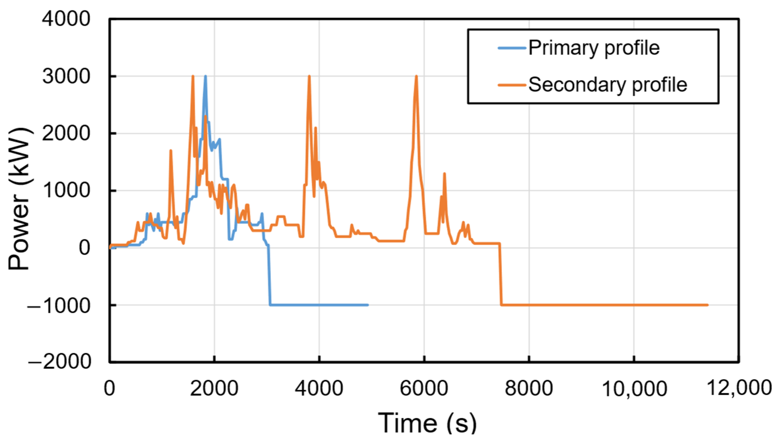
2. Target Ship and Requirements

The target vessel in this work was a full-electric harbor tug. Tugs are vessels specially designed to assist the other ships during maneuvers by forcing or tugging them toward the port and transporting the floating artifacts from one place to another. Figure 1 shows the electric tug RSD-E 2513 manufactured by DAMEN [23].
The harbor tug selected for this study possesses two different operational profiles. The first operational profile is known as the “primary cycle”, which is defined based on the nominal operation of the vessel. The second load profile, known as the “secondary cycle” is defined as the operations under non-standard circumstances. The tug fulfills 1095 primary and 52 secondary cycles per year. These operational profiles are depicted in Figure 2. It is obvious that the secondary cycle is much heavier than the primary one. Although the maximum power demanded by the tug is limited to 3000 kW for both cycles, the required energy to perform the primary cycle is 525 kWh, while the energy needed to fulfill the secondary cycle is 1100 kWh, almost two times larger than the primary cycle. For both cases, once the discharging process is done, the battery pack is charged at a fixed power of 1000 kW.
Three design requirements are assumed for sizing the baseline and HESS topologies as below:
  • The battery system is integrated into the vessel through a DC link with a fixed voltage of 1000 V.
  • The battery cells operate within the state of charge (SOC) of 90–10%. In other words, the maximum depth of discharge (DOD) is 80%.
  • The battery system has to fulfill 10 years of operation.

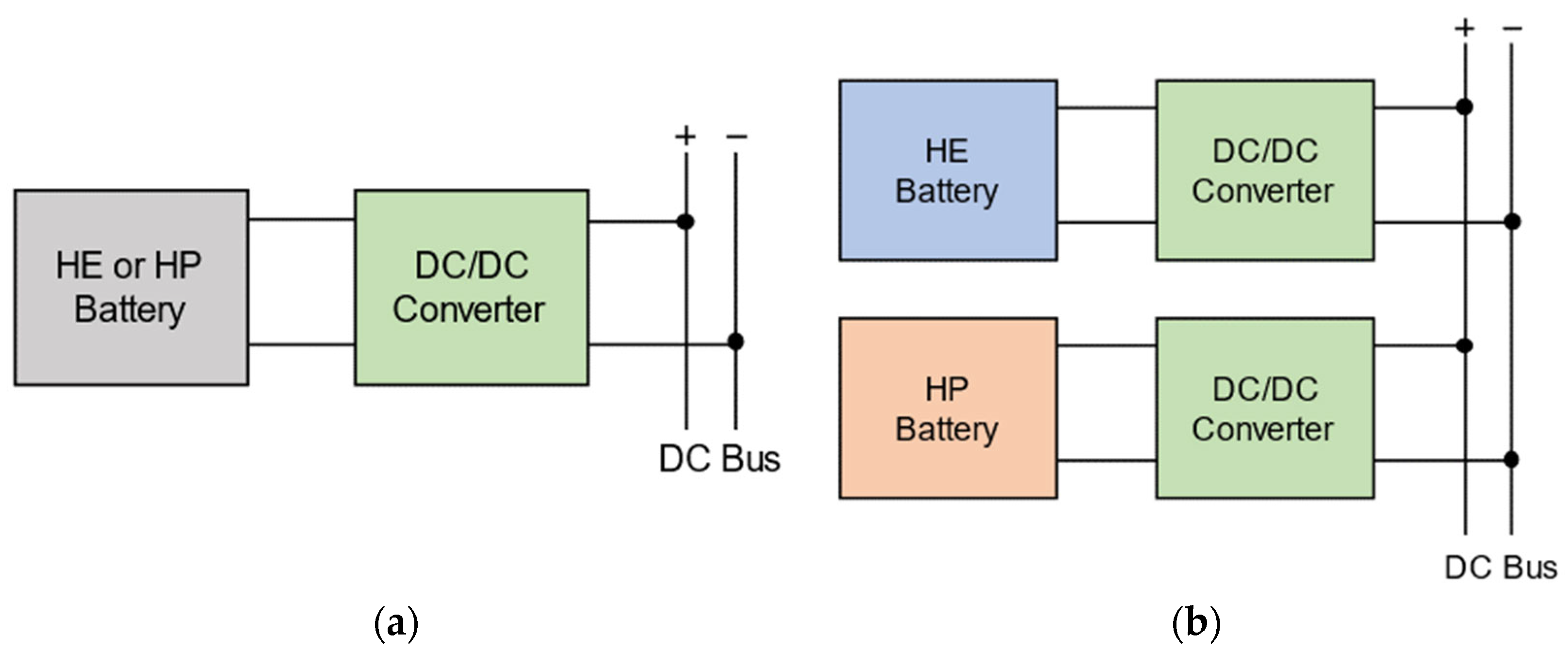
3. Baseline Battery System and HESS Topologies

As mentioned earlier, the baseline topology is formed on a monotype battery system inclusive of two cases; one with the HE cell and the other one with the HP cell. The battery system is connected to the DC bus through a bidirectional DC/DC converter to cope with the fixed voltage requirement. Figure 3a shows the schematic of the baseline battery system. The HE and HP batteries can be combined in different ways to form a HESS topology. In general, the HESS configurations are divided into passive, semi-active, and full-active topologies. In full-active HESS topologies, each energy storage unit is decoupled by the power electronic components. This allows an optimal operation of each energy storage based on their charge/discharge characteristics [24]. In this work, the hybrid battery system is based on a parallel full-active configuration where the HE and HP battery packs are connected to the DC link via separate DC/DC converters. Accordingly, the batteries are decoupled from each other and the load and can operate independently. Figure 3b illustrates the schematic of the parallel full-active HESS topology.

4. Specifications of Battery Cells and DC/DC Converter

The lithium nickel manganese cobalt oxide (NMC) and lithium titanate oxide (LTO) battery types are used as HE and HP batteries in this work. Both NMC and LTO are standard cell technologies in electric ships. Table 1 summarizes the main specifications of the battery and DC/DC converter.

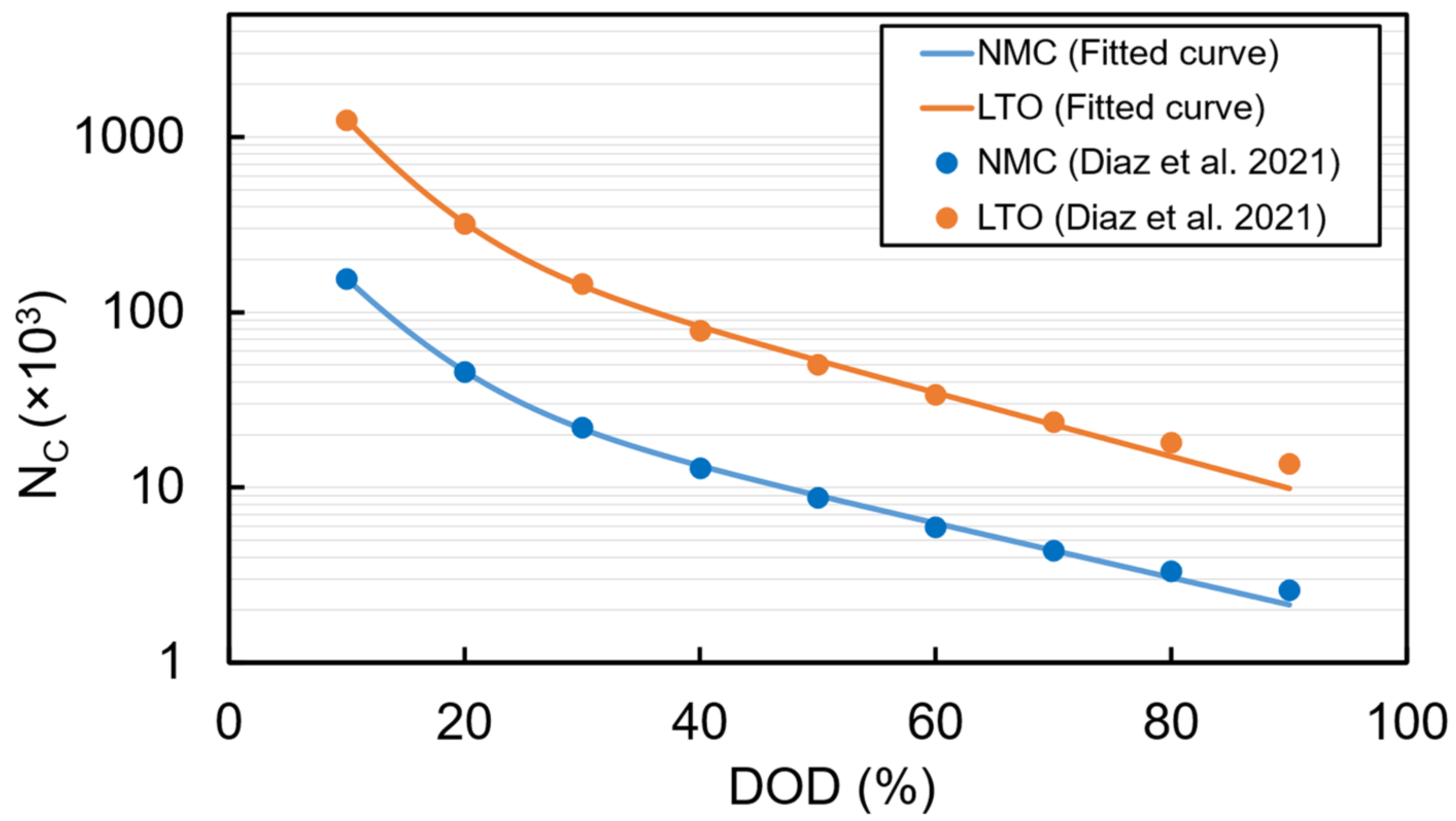
5. Battery Lifetime Model

The battery cell degradation is of great importance in sizing the battery systems, especially for marine applications which require a long battery system lifespan (at least 10 years). Accordingly, accurate lifetime models are needed to predict the reduction of capacity and power capability of batteries for optimal sizing of the battery system [25]. The degradation of the Li-ion batteries is characterized by cycle aging and calendar aging. The former is related to the battery capacity reduction while the battery is undergoing cycling. The latter is independent of battery discharge/charge cycles and represents the battery capacity reduction while the battery is not in use. In the present work, calendar aging is neglected, and only the influence of cycle aging on the capacity reduction of the batteries is taken into account.
The lifetime estimation of batteries can be realized through different approaches, which are categorized into offline and online methods. The offline method, which is also known as pure-lifetime models, provides information regarding the remaining useful lifetime of the battery [26]. The pure-lifetime models are also divided into two categories; throughput counting and cycle counting models. The cycle counting methodology is employed to estimate the lifetime of the batteries in this research. In the cycle counting approach, DOD is considered as the stress factor on battery lifetime. The higher the DOD, the fewer cycles the battery can undergo until reaching the end of life (EOL) [27]. In this method, the number of cycles that a battery can undergo before reaching the end of life ( N C ) can be formulated as [28]:
N C = a × e b × D O D + c × e d × D O D
where D O D is the depth of discharge which is defined as the usable battery energy over the installed energy and assumed to be a fixed value during the design life of the battery. Additionally, a , b , c , and d are constant fitting parameters. The number of cycles that the battery can undergo before reaching the end of life versus DOD for NMC and LTO battery types is extracted from [29]. The constant parameters are estimated using the least square fitting method by MATLAB. Figure 4 illustrates the fitted curves and the values extracted from Reference [29].

6. Sizing Methodology

This section presents the methodology for finding the optimal size of the HESS leading to the minimum battery pack cost. Based on the energy conservation principle, the relationship between the power of the HE/HP battery packs and the power demanded by the vessel for the primary and secondary load profiles are as follows.
P H E P t + P H P P t = P d P t P H E S t + P H P S t = P d S t
where P H E t and P H P t are the power of the HE and HP batteries, respectively, and P d t denotes the power demand. The superscripts P and S correspond to the primary and secondary load profiles. It should be noted that the power is positive during the discharge of batteries and negative during the charging process. The usable energy of the HE/HP battery packs for the primary profile ( E u s a b l e P ) and secondary profile ( E u s a b l e S ) can be calculated based on:
E u s a b l e P = P d i s P t . d t P E u s a b l e S = P d i s S t . d t S
where P d i s t is the discharge power of the HE/HP battery pack and d t is the time step. Based on the usable energy as well as the installed energy of the HE/HP battery pack, the DOD is defined as:
D O D P = E u s a b l e P E i n s D O D S = E u s a b l e S E i n s
where E i n s is the installed energy of the HE/HP battery pack. Based on the defined DODs and the lifetime model given in Section 5, the number of cycles that HE/HP battery can undergo before reaching the end of life can be calculated for both primary and secondary profiles ( N C P and N C S ). Considering the 80% state of health (SOH) of the batteries corresponding to the end of life, and assuming a uniform battery degradation over time, the percentage of the capacity loss ( C l o s s ) of the HE/HP battery pack during the design life of the vessel can be calculated as follows.
C l o s s = N d e s i g n   l i f e P N C P + N d e s i g n   l i f e S N C S × 20 %
where N d e s i g n   l i f e P and N d e s i g n   l i f e S are the total number of primary and secondary cycles that the batteries need to perform during the design life. As mentioned earlier, for this application, a design life of 10 years is required. Therefore, the number of primary and secondary cycles during the design life is:
N d e s i g n   l i f e P = 10,950 N d e s i g n   l i f e S = 520

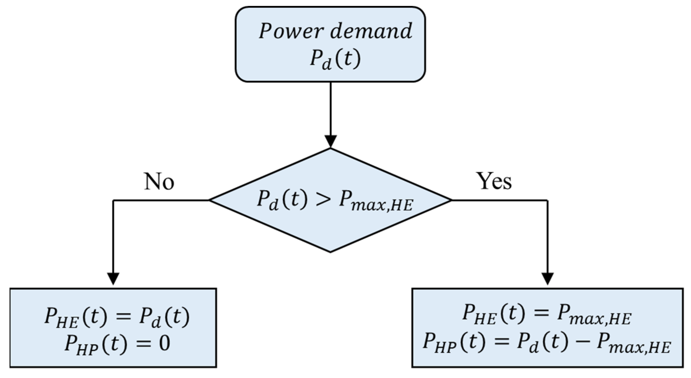
6.1. Energy Management Strategy

The power split between the HE and HP battery packs is realized through a rule-based energy management method. Considering the HE battery as the primary power source and the HP battery as ancillary energy storage, a power threshold ( P m a x , H E ) is defined as the maximum power supplied by the HE battery. The parameter P m a x , H E varies from 0 to 3000 kW (the maximum power in the load profiles). As long as the power demand from the vessel is less than P m a x , H E , only the HE battery supplies the required power. When the demanded power is beyond P m a x , H E , the HP battery supplies the additional required power. Figure 5 illustrates the rule-based energy management of the HESS that remains the same for both primary and secondary cycles.
The usable energy for each battery (Equation (3)) is calculated based on P H E t and P H P t as the outputs of the energy management system. Then, the next step is the determination of the installed energy to find the respective DoD for each battery. Taking into account the design requirements, four criteria must be met while calculating the installed energy as follows.
(1) The HE/HP battery pack must ensure 10 years of operation before reaching the end of life. To meet this criterion, a parameter ( E i n s 1 ) is defined as the minimum installed energy for each battery that ensures C l o s s 20 % .
(2) The HE/HP battery pack must ensure providing the required usable energy while the SOC of batteries remains between 10% to 90% during the design life. Therefore, the installed energy to meet this criterion ( E i n s 2 ) must satisfy the following equation for the HE/HP battery packs:
E i n s , 2 C l o s s × E i n s , 2 = M a x E u s a b l e P , E u s a b l e S 0.8
(3) To ensure that the input current to the HE/HP cell during the charging process does not exceed the standard charge current of the cell given in the datasheet (Table 1).
E i n s , 3   = M a x P c h P , P c h S × C a p c e l l I c h , c o n t
where P c h P and P c h S are the charging power of the HE/HP pack for primary and secondary profiles, C a p c e l l is battery capacity, and I c h , c o n t denotes the continuous charging current of the HE/HP cell.
(4) To ensure that the output current of the HE/HP cell during the discharging process does not exceed the standard discharge current of the cell given in the datasheet (Table 1).
E i n s , 4   = M a x P d i s c h P , P d i s c h S × C a p c e l l I d i s c h , c o n t
where P d i s c h P and P d i s c h S are the discharging power of the HE/HP pack for primary and secondary profiles. Besides, I d i s c h , c o n t denotes the continuous discharging current of the HE/HP cell.
Finally, the capacity to be installed for the HE/HP battery types while meeting all the above criteria is:
E i n s   = M a x E i n s , 1   , E i n s , 2   , E i n s , 3   , E i n s , 4  
Accordingly, the HESS cost is calculated by:
C o s t H E S S = E i n s , H E × C o s t H E + E i n s , H P × C o s t H P + C o s t D C / D C

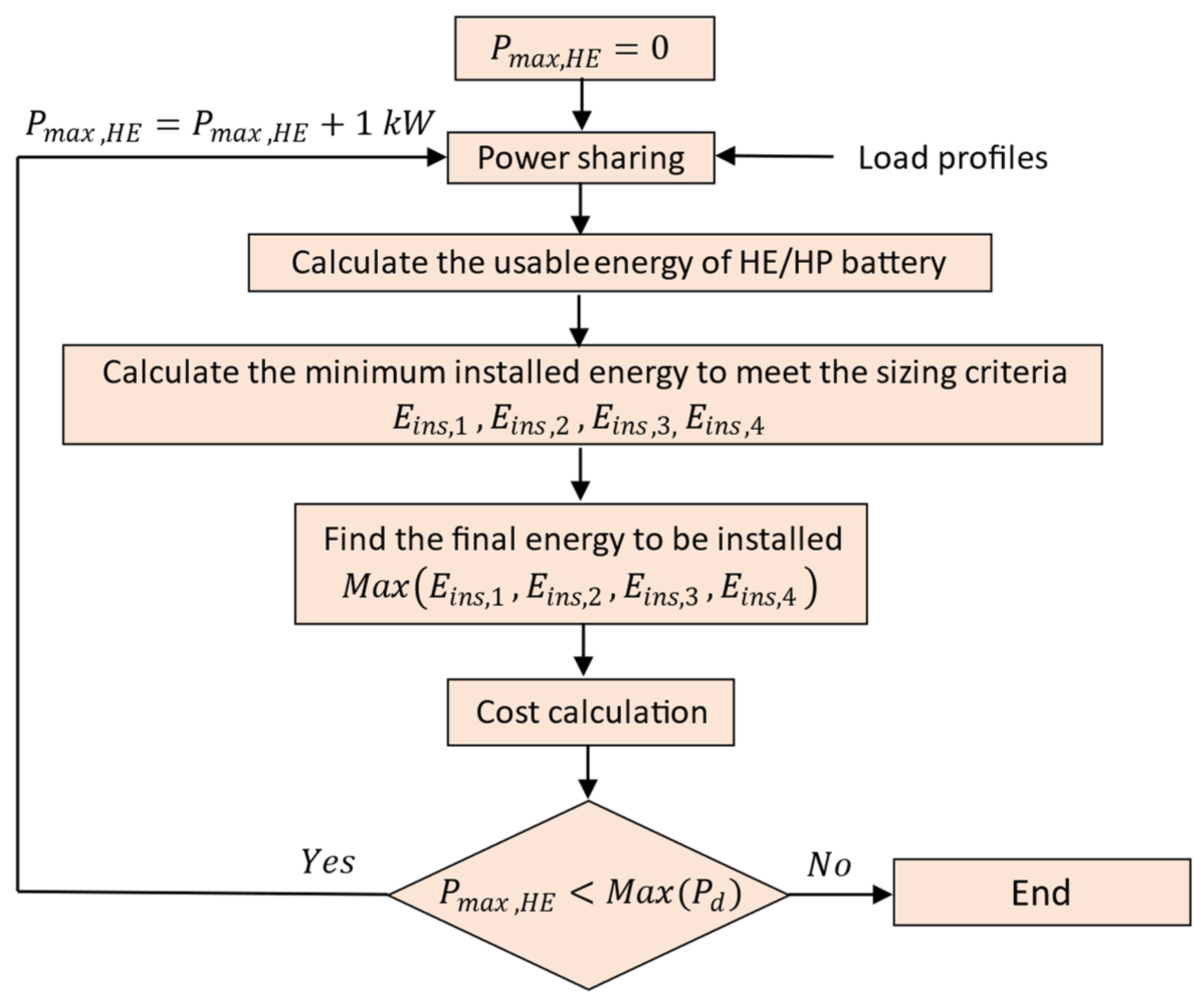
6.2. Sizing Flowchart

Figure 6 shows the flowchart of the HESS sizing and cost assessment at different values of P m a x , H E . As it is observed, the installed energy and HESS cost to are calculated for 1 kW intervals of P m a x , H E . It should be noted that P m a x , H E = 0 refers to the baseline topology with the HP cells, and P m a x , H E = M a x P d shows the baseline with the HE cell type. In this work, the sizing and cost calculation is performed by MATLAB scripting.

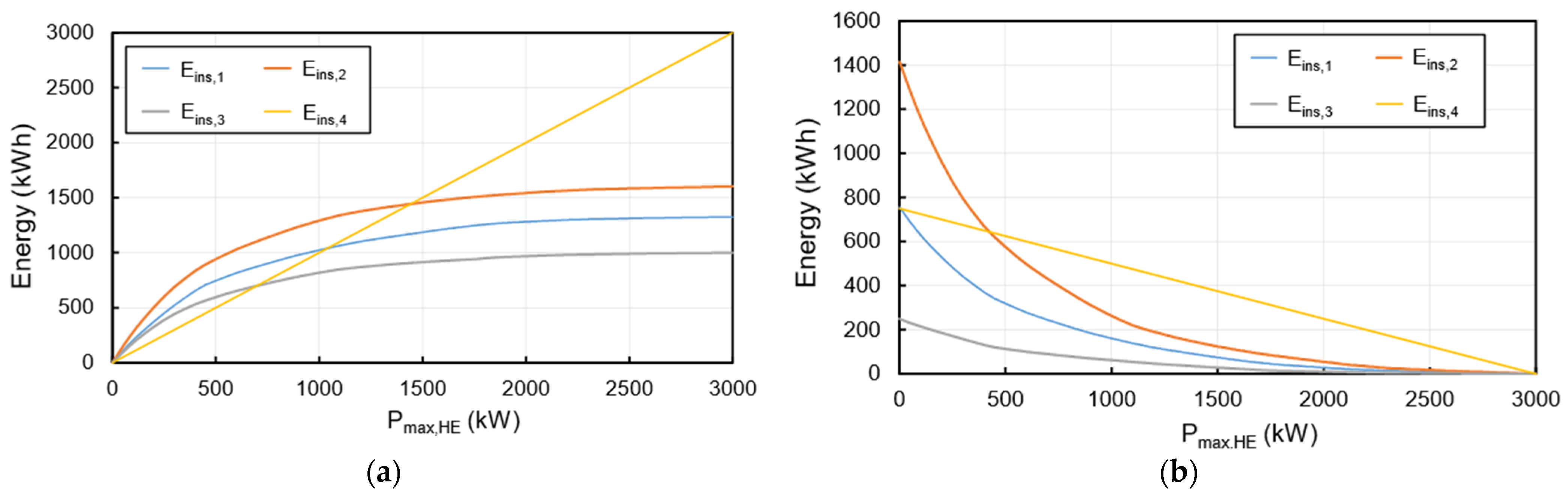
7. Results and Discussion

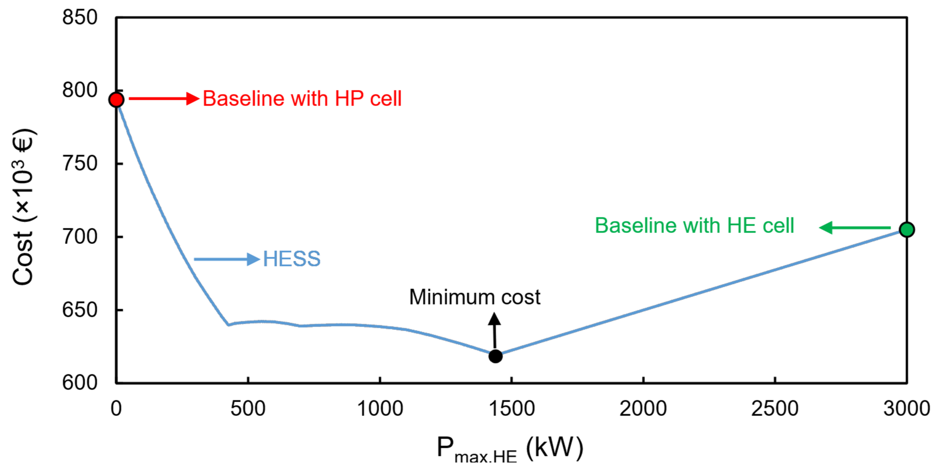
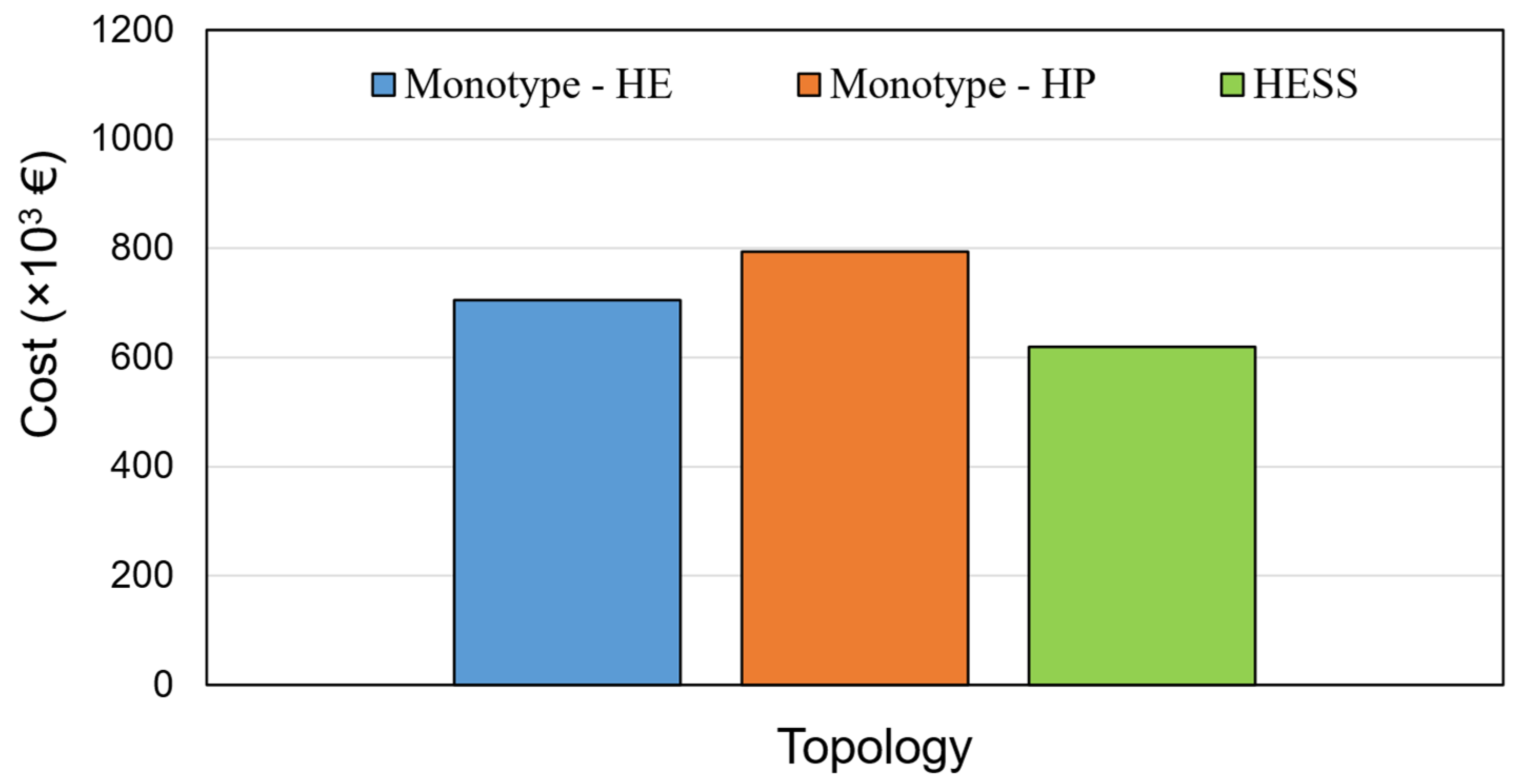
7.1. Battery Cost Analysis

This section presents the battery sizing and cost analysis results. Figure 7 shows the installed energies to fulfill the sizing criteria of E i n s , 1   , E i n s , 2   , E i n s , 3   , and E i n s , 4   versus P m a x , H E . As expected from the energy management strategy, increasing P m a x , H E increases in the installed energies for the HE battery, while it has a reverse influence on the HP battery type. Depending on P m a x , H E , the largest installed energy corresponds to E i n s , 2   and E i n s , 4   for both HE and HP batteries. As it is observed in Figure 7a, for P m a x , H E < 1442   kW , the required battery size to fulfill all sizing criteria for the HE battery is dictated by E i n s , 2   , while for the P m a x , H E > 1442   kW the installed energy is dictated by E i n s , 4   . Regarding the HP battery, E i n s , 2   is the largest installed energy for the power thresholds of P m a x , H E 425 kW, while the size of the installed battery depends on E i n s , 4   when P m a x , H E 425   kW . Therefore, depending on P m a x , H E , the discharging power and battery degradation have a considerable impact on the size of the installed battery for both battery types to meet the design criteria.
Figure 8 depicts the cost (including the price of the cells and DC/DC converter) for the baseline and HESS topology versus P m a x , H E . As it is seen, a minimum cost is found for the HESS at P m a x , H E = 1442   kW . At this point, according to Figure 7, the required installed capacity for the HE and HP batteries is 1442 kWh and 389 kWh, respectively. Regarding the monotype battery topology, the installed energy for the baseline with the HE cell is 3000 kWh, while the installed energy is 1415 kWh for the baseline with the HP cell.
Figure 9 compares the cost of a monotype battery system with the optimal HESS cost. As expected from Figure 8, the highest cost corresponds to the baseline topology with the HP battery cell followed by the baseline with the HE cell. According to the cost analysis results given in Figure 9, the HESS with an optimal energy management strategy leads to a 28% lower cost than the monotype HP system and around 14% lower cost compared to the monotype HE system.
The value of cost reduction achieved in this work is comparable to other studies focused on the use of the HE and HP Li-ion batteries for automotive applications. For instance, according to Reference [15], a HESS composed of LFP and LTO cells resulted in a 19.3% lower cost compared to a single LFP battery pack, and a 10.7% lower cost than a single LTO battery pack for an electric bus.
Figure 10a,b show the optimal power split between the HE and HP battery packs within the HESS for the primary and secondary cycles. As a result of the previous figures, the optimal power split corresponds to P m a x , H E = 1442   kW . It is seen that the HE battery provides long-term power needs, while the HP battery assists the HE battery with short duration but higher power needs. Consequently, the energy provided by the HE battery for the primary cycle is 458 kWh, while 67 kWh is provided by the HP battery. Regarding the secondary cycle, the energies provided by the HE and HP battery types are 998 kWh and 103 kWh, respectively.

7.2. Battery System Losses
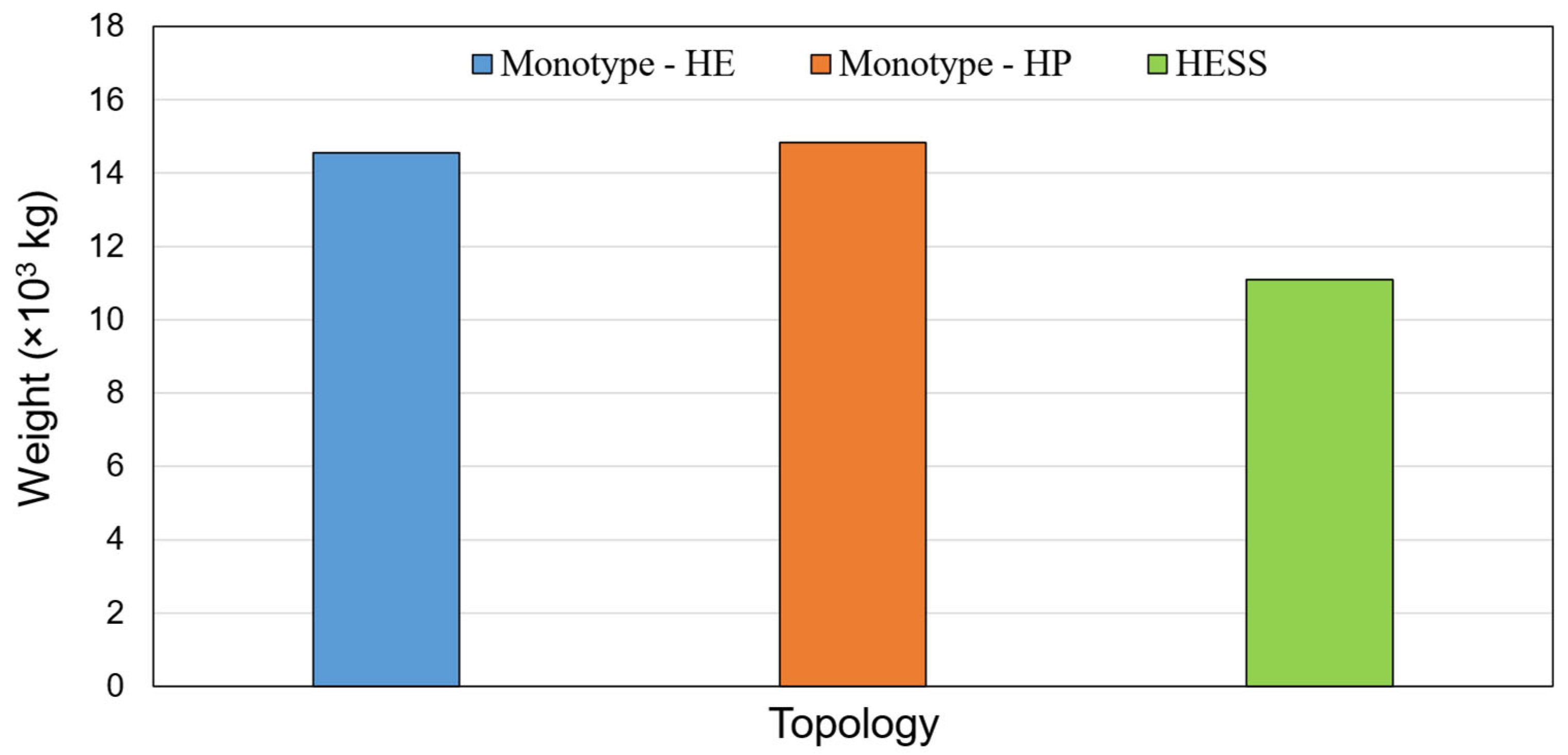
In this section, the system losses are calculated and compared for the baseline system and the cost-optimal HESS. First, the number of cells in series and parallel is calculated for each case. The number of cells in series depends on the required voltage of the DC link, which is calculated as follows.
N s = V D C V c e l l , n o m
where N s denotes the number of cells in series, V D C is the voltage of the DC bus and V c e l l , n o m is the nominal voltage of the cell. As mentioned earlier, the voltage of the DC bus is 1000 V, and the nominal voltage of the HE and HP cells are 3.65 V and 2.3 V, as given in Table 1. Once the number of cells in series is calculated for each battery string, then the number of parallel groups can be calculated based on the installed energy found in the previous section as below:
N P = E i n s N S × E c e l l
where N P is the number of parallel strings within the battery pack, E i n s shows the installed energy and E c e l l is the energy of every single cell. The energy for each cell is calculated based on the cell weight and its energy density given in Table 1. As a result, Table 2 presents the number of cells for each battery topology.
Then, having the number of series cells and parallel groups and assuming the voltage of the batteries remain at the nominal value, the power loss for each battery system P l o s s is obtained based on the cell’s internal resistance from Table 1:
P l o s s , b a t t e r y = N s N P R c e l l V D C P 2
where R c e l l is the cell’s internal resistance and P is the output/input power of each battery pack. Moreover, the power loss of the converter is determined based on its efficiency.
P l o s s ,     D C / D C = 1 η D C / D C × P
The total system losses can be calculated based on the annual energy throughput ( A E T ) and the annual energy losses ( A E L ) associated with a given load profile.
η = 1 A E L A E T × 100
A E T = 2 × ( P d i s P t . d t P × N A n n u a l P + P d i s S t . d t S . d t × N A n n u a l S ) A E L = P l o s s , t o t P t . d t P × N A n n u a l P + P l o s s , t o t S t . d t S × N A n n u a l S
In Equation (17), P d i s shows the total discharge power, N A n n u a l is the number of cycles per year, and P l o s s , t o t is the summation of the battery and DC/DC power losses. In the above equation, the superscripts P and S refer to the primary and secondary cycles.
Figure 11 shows the total battery system efficiency, including the losses of batteries and converter. As it is seen, the highest efficiency corresponds to the HE monotype battery, followed by the HP monotype and HESS. On the one hand, the input/output power of the HE/HP battery packs in HESS is lower than the monotype systems leading to lower power loss. On the other hand, the number of parallel strings in the HESS is lower than in the monotype system, which has an inverse effect on the power loss. That is why there is no considerable difference in the efficiency for the three cases. As an example, the efficiency of the HE monotype system is only 0.2% higher than HESS. Nevertheless, the efficiency of all cases is higher than 98%.

7.3. Battery Weight

The weight of the battery cells has a significant impact on the entire battery system weight. The lower the battery weight, the higher the specific energy can be gained. Figure 12 compares the weight of the battery cells in the monotype systems and the cost-optimal HESS. The weight of the cells depends on the total number of cells installed in each battery system. Based on the cell numbers from Table 2, and the weight of a single HP/HE cell from Table 1, the total weight of the cells for each case is calculated. As can be seen in Figure 12, battery hybridization can significantly reduce the total weight of the battery cells. The highest weight corresponds to the monotype HP system, followed by the monotype HE system and HESS. The weight of the HE monotype battery is 2.3% lower than the HP monotype, while the weight of the HESS is 33.5% lower than the HP monotype system.

8. Conclusions

In this work, the impact of battery hybridization on the cost, efficiency, and weight of the battery system was investigated for a harbor tug with an electric propulsion system. The hybrid battery system was based on a parallel full-active topology using NMC and LTO battery chemistries. The battery pack was sized for a design life of 10 years based on the cycle-counting lifetime model. Using a rule-based energy management method, an optimal HESS cost was obtained leading to 28% and 14% lower costs in comparison with a monotype battery system with LTO and NMC cells, respectively. The cost-optimal HESS system was more than 30% lighter than the monotype battery systems, while there is no notable difference between the HESS and monotype battery systems with respect to the system efficiency. Accordingly, a well-designed HESS can significantly reduce the cost and the weight of large battery systems for marine applications and speed up the transition toward zero-emission vessels.

Author Contributions

Conceptualization, M.A.; investigation, M.A.; methodology, M.A.; project administration, J.D.S. and J.S.; writing—original draft, M.A.; writing—review and editing, J.D.S. and J.S. All authors have read and agreed to the published version of the manuscript.

Funding

This research has received funding from the European Union’s Horizon 2020 research and innovation programme under grant agreement no. 963560. Processes 10 02418 i001

Data Availability Statement

Not applicable.

Acknowledgments

This research was developed under the framework of SEABAT project—“Solutions for largE bAtteries for waterBorne trAnsporT”.

Conflicts of Interest

The authors declare no conflict of interest.

References

  1. Enweremadu, C.; Samuel, O.; Rutto, H. Experimental Studies and Theoretical Modelling of Diesel Engine Running on Biodiesels from South African Sunflower and Canola Oils. Environ. Clim. Technol. 2022, 26, 630–647. [Google Scholar] [CrossRef]
  2. Elumalai, P.V.; Moorthy, R.K.; Parthasarathy, M.; Samuel, O.D.; Owamah, H.I.; Saleel, C.A.; Enweremadu, C.C.; Reddy, M.S.; Afzal, A. Artificial neural networks model for predicting the behavior of different injection pressure characteristics powered by blend of biofuel-nano emulsion. Energy Sci. Eng. 2022, 10, 2367–2396. [Google Scholar] [CrossRef]
  3. Chen, H.; Zhang, Z.; Guan, C.; Gao, H. Optimization of sizing and frequency control in battery/supercapacitor hybrid energy storage system for fuel cell ship. Energy 2020, 197, 117285. [Google Scholar] [CrossRef]
  4. Pan, P.; Sun, Y.; Yuan, C.; Yan, X.; Tang, X. Research progress on ship power systems integrated with new energy sources: A review. Renew. Sustain. Energy Rev. 2021, 144, 111048. [Google Scholar] [CrossRef]
  5. Mutarraf, M.U.; Terriche, Y.; Niazi, K.A.K.; Vasquez, J.C.; Guerrero, J.M. Energy Storage Systems for Shipboard Microgrids—A Review. Energies 2018, 11, 3492. [Google Scholar] [CrossRef] [Green Version]
  6. Yuan, Y.; Wang, J.; Yan, X.; Shen, B.; Long, T. A review of multi-energy hybrid power system for ships. Renew. Sustain. Energy Rev. 2020, 132, 110081. [Google Scholar] [CrossRef]
  7. Smith, T.W.P.; Jalkanen, J.P.; Anderson, B.A.; Corbett, J.J.; Faber, J.; Hanayama, S.; O’Keeffe, E.; Parker, S.; Johansson, L.; Aldous, L.; et al. Third IMO Greenhouse Gas Study 2014; International Maritime Organization: London, UK, 2014. [Google Scholar]
  8. Mokashi, I.; Afzal, A.; Khan, S.A.; Abdullah, N.A.; Azami, M.H.B.; Jilte, R.D.; Samuele, O.D. Nusselt number analysis from a battery pack cooled by different fluids and multiple back-propagation modelling using feed-forward networks. Int. J. Therm. Sci. 2021, 161, 106738. [Google Scholar] [CrossRef]
  9. Becker, J.; Nemeth, T.; Wegmann, R.; Sauer, D.U. Dimensioning and Optimization of Hybrid Li-Ion Battery Systems for EVs. World Electr. Veh. J. 2018, 9, 19. [Google Scholar]
  10. Syb ten Cate Hoedemaker. Solutions for Large Batteries for Waterborne Transport, D2.1–Application Matrix; SEABAT; Uniresearch BV: Delft, The Netherlands, 2021. [Google Scholar]
  11. Bocklisch, T. Hybrid energy storage approach for renewable energy applications. J. Energy Storage 2016, 8, 311–319. [Google Scholar] [CrossRef]
  12. Kouchachvili, L.; Yaïci, W.; Entchev, E. Hybrid battery/supercapacitor energy storage system for the electric. J. Power Sources 2018, 374, 237–248. [Google Scholar] [CrossRef]
  13. Song, Z.; Li, J.; Hou, J.; Hofmann, H.; Ouyang, M.; Du, J. The battery-supercapacitor hybrid energy storage system in electric vehicle applications: A case study. Energy 2018, 154, 433–441. [Google Scholar] [CrossRef]
  14. Nemeth, T.; Kollmeyer, P.J.; Emadi, A.; Sauer, D.U. Optimized Operation of a Hybrid Energy Storage System with LTO Batteries for High Power Electrified Vehicles. In Proceedings of the 2019 IEEE Transportation Electrification Conference and Expo (ITEC), Detroit, MI, USA, 19–21 June 2019. [Google Scholar]
  15. Zhang, X.; Peng, H.; Wang, H.; Ouyang, M. Hybrid Lithium Iron Phosphate Battery and Lithium Titanate Battery Systems for Electric Buses. IEEE Trans. Veh. Technol. 2017, 67, 956–965. [Google Scholar] [CrossRef]
  16. Degaa, L.; Rizoug, N.; Bendjedia, B.; Saidane, A.; Larouci, C. Sizing improvement of hybrid storage system composed with high energy and high power Li-ion batteries for automotive applications. J. Syst. Control Eng. 2019, 233, 870–876. [Google Scholar] [CrossRef]
  17. Min, H.; Lai, C.; Yu, Y.; Zhu, T.; Zhang, C. Comparison Study of Two Semi-Active Hybrid Energy Storage Systems for Hybrid Electric Vehicle Applications and Their Experimental Validation. Energies 2017, 10, 279. [Google Scholar] [CrossRef] [Green Version]
  18. Zhuanga, W.; Yea, J.; Songb, Z.; Yina, G.; Lia, G. Comparison of semi-active hybrid battery system configurations for electric taxis application. Appl. Energy 2020, 259, 11471. [Google Scholar] [CrossRef]
  19. Wieczorek, M.; Lewandowski, M.; Staroński, K.; Pierzchała, M. Experimental Validation of Energy Management Strategy in Hybrid Energy Storage System for Electric Vehicle. In Proceedings of the 2018 IEEE Transportation Electrification Conference and Expo (ITEC), Long Beach, CA, USA, 13–15 June 2018. [Google Scholar]
  20. Kim, K.; An, J.; Park, K.; Roh, G.; Chun, K. Analysis of a Supercapacitor/Battery Hybrid Power System for a Bulk Carrier. Appl. Sci. 2019, 9, 1547. [Google Scholar] [CrossRef] [Green Version]
  21. Balsamo, F.; Capasso, C.; Lauria, D.; Veneri, O. Optimal design and energy management of hybrid storage systems for marine propulsion applications. Appl. Energy 2020, 278, 115629. [Google Scholar] [CrossRef]
  22. Batteries Onboard Ocean-Going Vessels; MAN Energy Solutions: Copenhagen, Denmark, 2019.
  23. DAMEN RSD-E-Tug. Available online: https://products.damen.com/-/media/Products/Images/Clusters-groups/Tugs/RSD-Tugs/RSD-E-Tug/Documents/RSD_2513_Brochure.pdf (accessed on 7 October 2022).
  24. Zimmermann, T.; Keil, P.; Hofmann, M.; Horsche, M.F.; Pichlmaier, S. Review of system topologies for hybrid electrical energy storage systems. J. Energy Storage 2016, 8, 78–90. [Google Scholar] [CrossRef]
  25. Schaltz, E.; Khaligh, A.; Rasmussen, P.O. Influence of Battery/Ultracapacitor Energy-Storage Sizing on Battery Lifetime in a Fuel Cell Hybrid Electric Vehicle. IEEE Trans. Veh. Technol. 2009, 58, 3882–3891. [Google Scholar] [CrossRef]
  26. Stroe, D.I. Lifetime Models for Lithium-Ion Batteries Used in Virtual Power Plant Applications. Ph.D. Thesis, Department of Energy Technology, Aalborg University, Aalborg, Denmark, 2014. [Google Scholar]
  27. Stroe, D.I.; Świerczyński, M.; Stan, A.I.; Teodorescu, R.; Andreasen, S.J. Accelerated Lifetime Testing Methodology for Lifetime Estimation of Lithium-Ion Batteries Used in Augmented Wind Power Plants. IEEE Trans. Ind. Appl. 2014, 50, 4006–4017. [Google Scholar] [CrossRef]
  28. Bao, X.; Xu, X.; Zhang, Y.; Xiong, Y.; Shang, C. Optimal Sizing of Battery Energy Storage System in a Shipboard Power System with considering Energy Management Optimization. Discrete Dyn. Nat. Soc. 2021, 2021, 9032206. [Google Scholar] [CrossRef]
  29. Diaz, V.S.; Cantane, D.A.; Santos, A.Q.O.; Junior, O.H.A. Comparative Analysis of Degradation Assessment of Battery Energy Storage Systems in PV Smoothing Application. Energies 2021, 14, 3600. [Google Scholar] [CrossRef]
Figure 1. Damen RSD-E Tug 2513 [23].
Processes 10 02418 g001
Figure 2. Primary and secondary load profiles of the full-electric harbor tug.
Processes 10 02418 g002
Figure 3. Schematic of battery system topologies: (a) monotype, (b) HESS topology.
Processes 10 02418 g003
Figure 4. Number of cycles versus DOD [29].
Processes 10 02418 g004
Figure 5. Rule-based energy management strategy.
Processes 10 02418 g005
Figure 6. Sizing and cost assessment flow chart.
Processes 10 02418 g006
Figure 7. Installed energy based on different design criteria: (a) HE battery (b) HP battery.
Processes 10 02418 g007
Figure 8. Cost of the HESS and monotype battery systems versus P m a x , H E .
Processes 10 02418 g008
Figure 9. Cost of monotype systems and optimal HESS.
Processes 10 02418 g009
Figure 10. Optimal power split between HE and HP battery packs in HESS: (a) primary profile, (b) secondary profile.
Processes 10 02418 g010
Figure 11. Battery system efficiency.
Processes 10 02418 g011
Figure 12. Total battery cell weight for the monotype and cost-optimal HESS.
Processes 10 02418 g012
Table 1. Battery and DC/DC converter specifications.
ParameterValue
ChemistryNMC (HE cell)LTO (HP cell)
Capacity50 Ah23 Ah
Nominal voltage3.65 V2.3 V
Standard charge/discharge C-rate1/14/4
Energy density206 Wh/kg96 Wh/kg
Weight0.885 kg0.55 kg
Internal resistance1.5 mΩ1.1 mΩ
Battery cost150 €380 €
DC/DC converter efficiency0.98
DC/DC cost85 €/kW
Table 2. The number of cells in each battery topology.
MonotypeMonotypeHESS
Cell typeHEHPHEHP
N s 274435274435
N P 60622917
Total number of cells16,44026,97079467395
Publisher’s Note: MDPI stays neutral with regard to jurisdictional claims in published maps and institutional affiliations.

