

Effects of Low Pressure Injection on Fuel Atomization and Mixture Formation for Heavy Fuel Engines


Abstract
:1. Introduction
2. Modeling and Settings
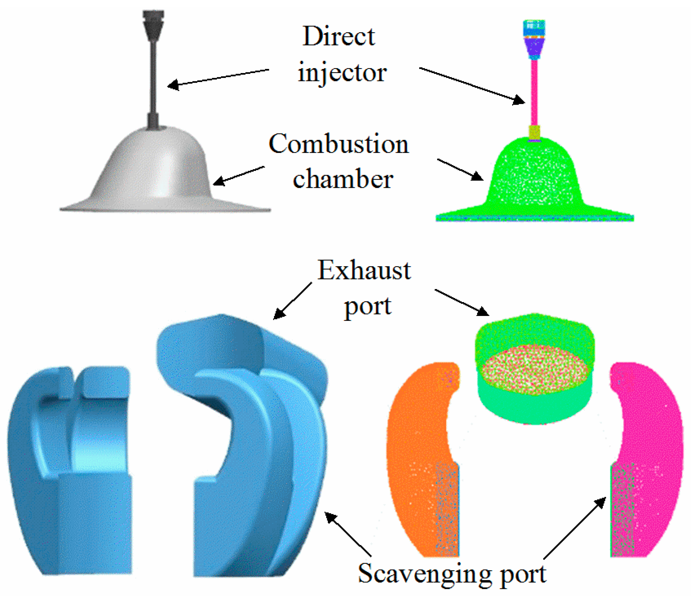
2.1. Meshing of the Three-Dimensional Calculation Model
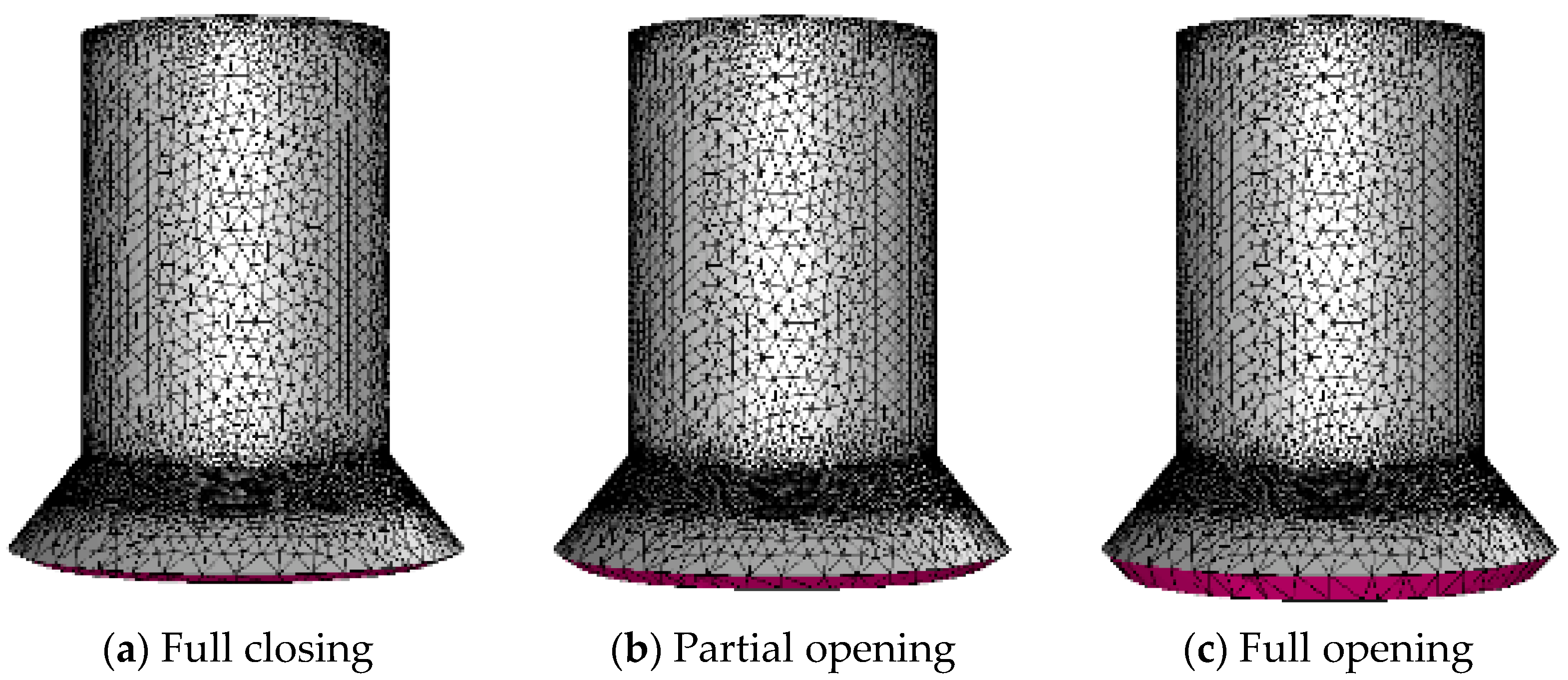
2.2. Dynamic Mesh
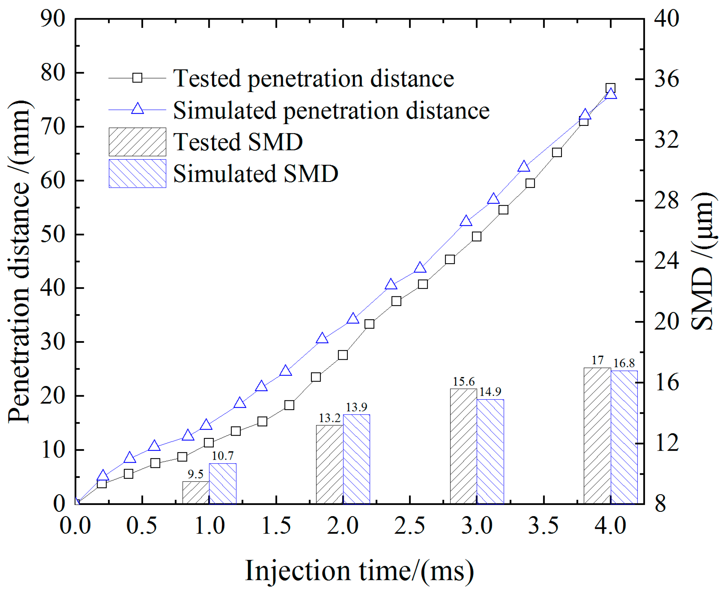
2.3. Injector Model
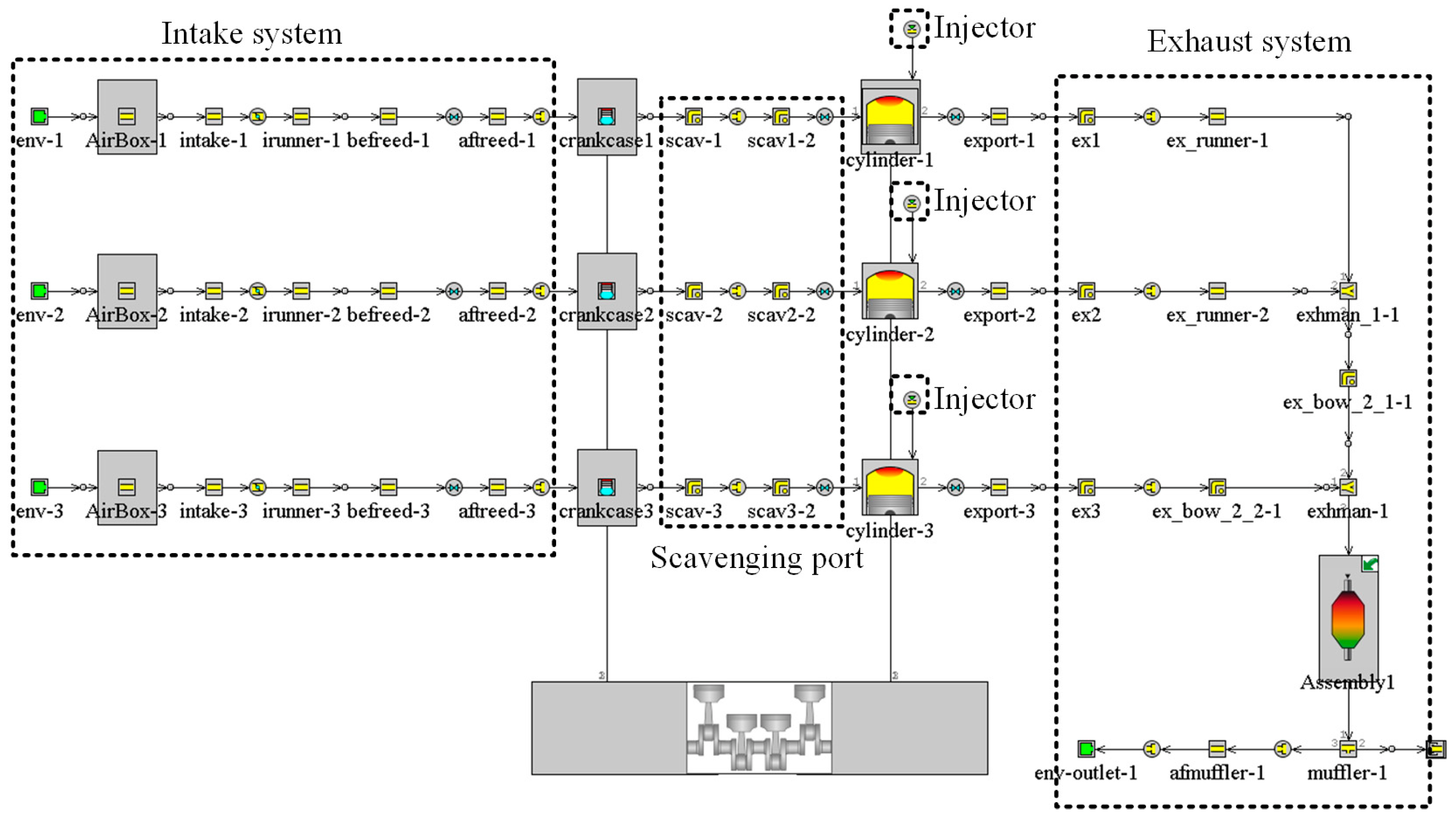
2.4. Initial Conditions and Boundary Conditions
3. Heavy Fuel Atomization and Mixture Formation Analysis
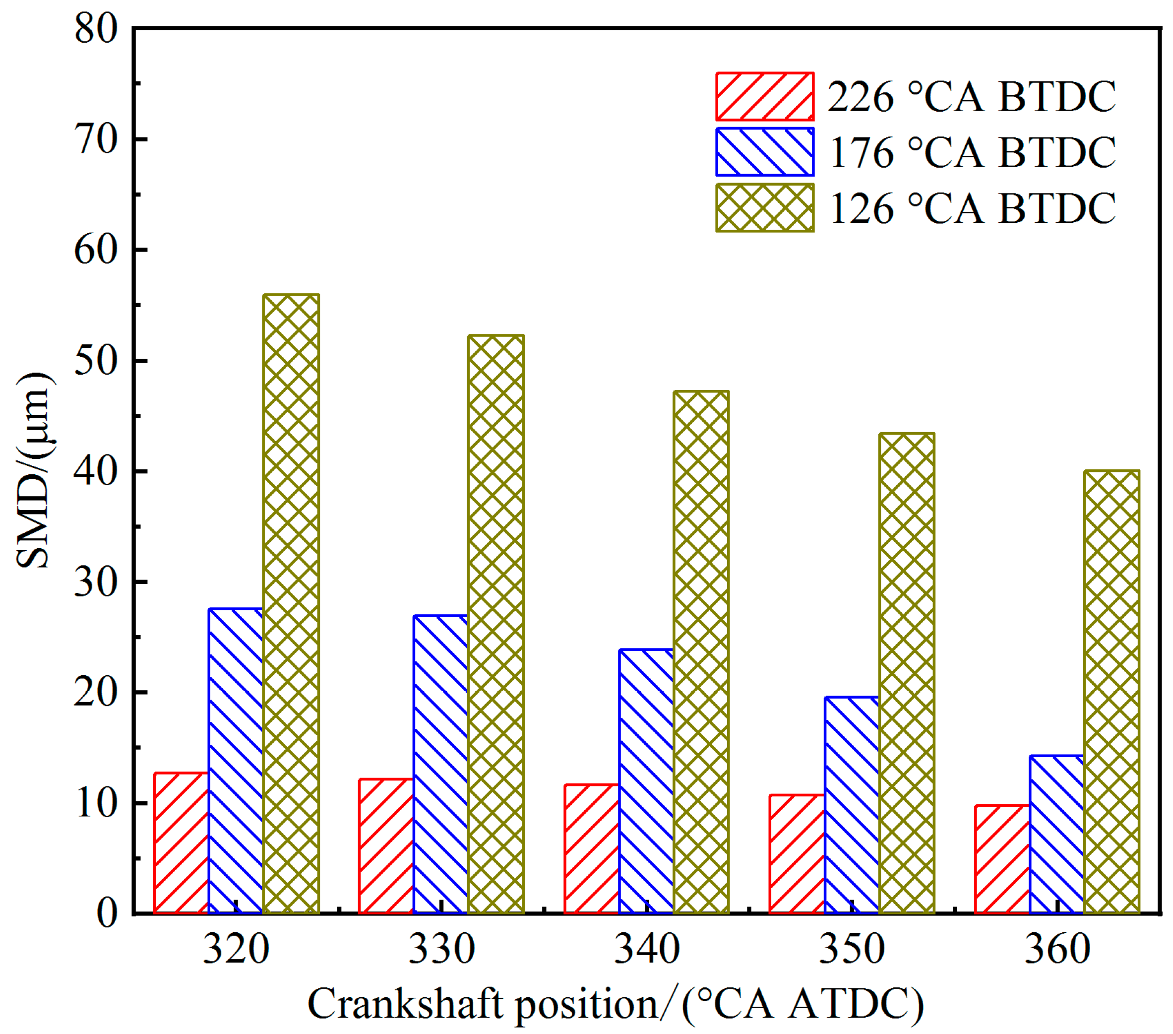
3.1. Effects of Injection Timing on Fuel Atomization and Mixture Formation
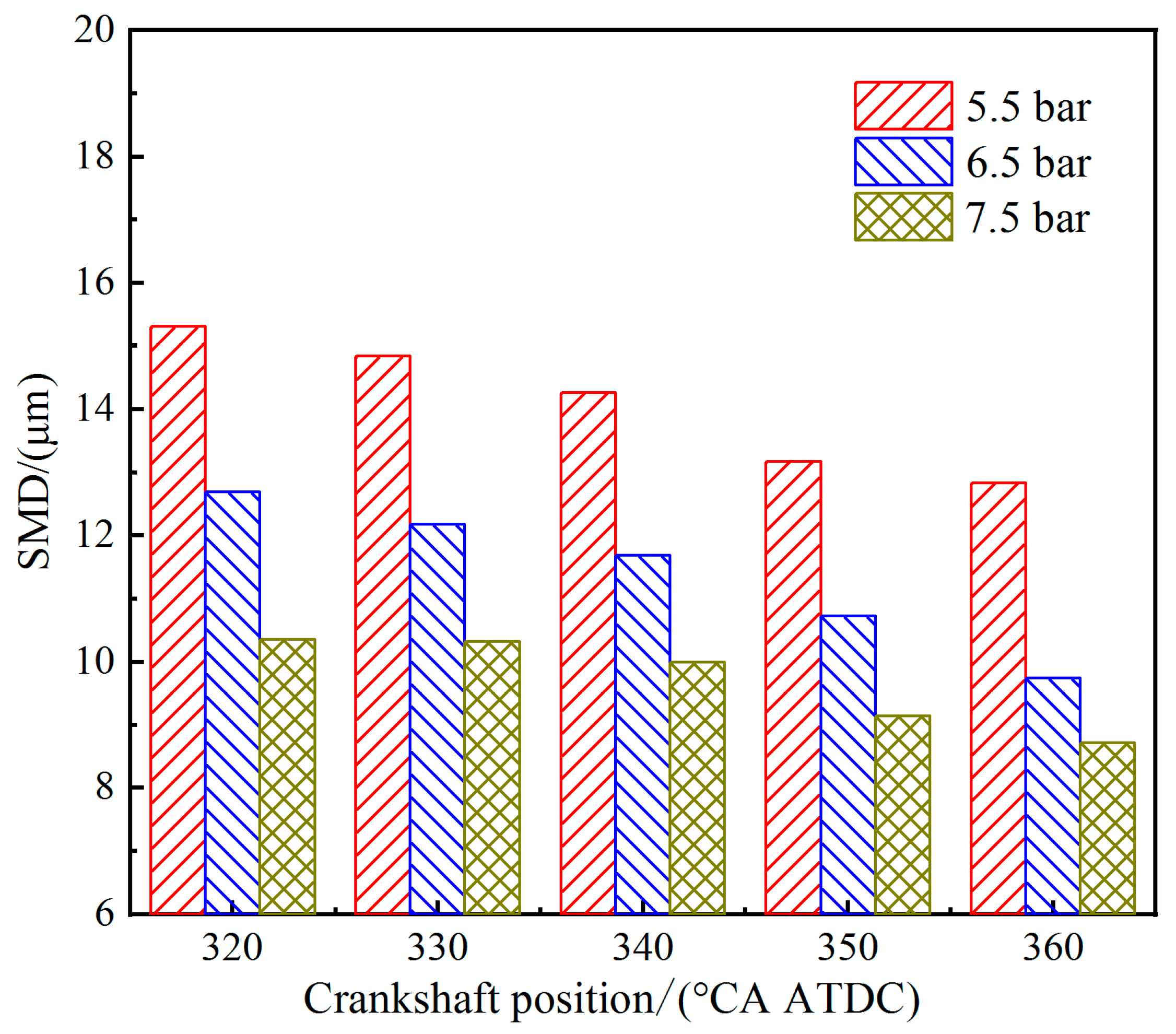
3.2. Effects of Injection Pressure on Fuel Atomization and Mixture Formation
4. Conclusions
- The concentration distribution of a combustible mixture in-cylinder is more uniform and the fuel evaporation mass fraction increases after the injection timing is advanced; early injection timings can make the heavy fuel evaporate with sufficient time; the later the injection timing, the larger the overall SMD of the fuel droplets; in addition, premature injection timings will exacerbate the fuel losses.
- With the increase in injection pressure, the concentration distribution of the combustible mixture in-cylinder is more uniform, which is conducive to the decrease in the overall SMD of the fuel droplets and the propagation of the flame in the cylinder; as the air injection pressures change from 6.5 bar to 7.5 bar, the variations in fuel particle size are small, and the fuel atomization effect remains at a favorable level.
- This research provides an improved simulation model for heavy fuel spray atomization and mixture formation. The results can provide theoretical support for the optimization of the fuel injection parameters of two-stroke DISI HFEs. Due to the limitation of time and conditions, this research did carried out detailed bench test research under different injection pressures and injection timings, which should be tested and verified in subsequent research work. This study hopes to contribute to the development of fuel injection control technology for small unmanned vehicles, drones, and all-terrain vehicles.
Author Contributions
Funding
Institutional Review Board Statement
Informed Consent Statement
Data Availability Statement
Acknowledgments
Conflicts of Interest
References
- Wang, C.; Lu, J.; Ren, Z.; Wan, Z.; Zhao, Z. Current development state and investigation of application for small piston aero-engine. In Proceedings of the 9th Youth Science and Technology Forum of Chinese Aeronautical Society, Xian, China, 17 November 2020; pp. 324–330. [Google Scholar]
- Lu, D.; Zheng, J.; Hu, C. Study on the development status of general aviation piston engine. Intern. Combust. Engines Parts 2019, 10, 64–66. [Google Scholar]
- Xu, J.; Nie, K.; Huang, G.; Sheng, Y. Control of torque and air-fuel ratio of compression-ignition aero piston engine. J. Aerosp. Power 2021, 36, 1083–1093. [Google Scholar]
- Du, C.; Tian, M.; Hu, C. Technical development analysis of two-stroke heavy fuel aero engine. Small Intern. Combust. Engine Veh. Technol. 2020, 49, 92–96. [Google Scholar]
- Liu, R.; Wei, M.; Yang, H. Cold start control strategy for a two-stroke spark ignition diesel-fuelled engine with air-assisted direct injection. Appl. Therm. Eng. 2016, 108, 414–426. [Google Scholar] [CrossRef]
- Wei, M.; Liu, R.; Yang, H.; Bei, T.; Ji, H.; Chang, C. Partial load experiments on a two-stroke spark ignition direct injection heavy fuel engine. J. Aerosp. Power 2017, 32, 2919–2926. [Google Scholar]
- Queiroz, C.; Tomanik, E. Gasoline Direct Injection Engines—A Bibliographical Review; SAE Technical Paper 973113; SAE International: Warrendale, PA, USA, 1997. [Google Scholar]
- Li, C. Study on the Mixture Formation and Combustion of Light-Weight High-Speed Heavy Oil Aeroengine. Master’s Thesis, Beijing Jiaotong University, Beijing, China, 2014. [Google Scholar]
- Hu, C.M.; Wang, S.D.; Bi, Y.F.; Zhong, W.J. Combustion characteristics of direct injection piston aviation kerosene engine. J. Aerosp. Power 2017, 32, 1035–1042. [Google Scholar]
- Chen, Z.; Qin, T.; He, T.; Zhu, L. Effect of equivalence ratio on diesel direct injection spark ignition combustion. J. Cent. South Univ. 2020, 27, 2338–2352. [Google Scholar] [CrossRef]
- Chen, Z.; Liao, B.; Yu, Y.; Qin, T. Effect of equivalence ratio on spark ignition combustion of an air-assisted direct injection heavy-fuel two-stroke engine. Fuel 2022, 313, 122646. [Google Scholar] [CrossRef]
- Zhao, Z.; Yu, C.; Dong, X.; Wang, L. Research on mixture formation of two-stroke heavy fuel direct injection engine. J. Aerosp. Power 2021, 36, 1569–1577. [Google Scholar]
- Huang, L. CFD Simulation Study of the Fuel-Air Mixture Formation in Cylinder of the Two-stroke Heavy Fuel Spark Ignition Engine. Master’s Thesis, Nanjing University of Aeronautics and Astronautics, Nanjing, China, 2016. [Google Scholar]
- Wang, S. Research on GDI Technology of Small Model Two-Stroke Kerosene Engine. Master’s Thesis, Nanjing University of Aeronautics and Astronautics, Nanjing, China, 2017. [Google Scholar]
- Wang, S.; Yang, H. Simulation on Atomization Mechanism of Air-Assisted Injector for Aircraft Heavy Fuel Engine. Trans. CSICE 2018, 36, 127–135. [Google Scholar]
- Ji, H.; Wu, H.; Yang, H.; Liu, H.; Rui, L. Numerical simulation of diesel spray characteristics based on air-assisted atomization injection. J. Aerosp. Power 2022, 37, 1284–1294. [Google Scholar]
- Shih, T.-H.; Liou, W.; Shabbir, A.; Yang, Z.; Zhu, J. A new k-ϵ eddy viscosity model for high reynolds number turbulent flows. Comput. Fluids 1995, 24, 227–238. [Google Scholar] [CrossRef]
- O’Rourke, P. The TAB Method for Numerical Calculation of Spray Droplet Breakup; SAE Technical Paper 872089; SAE International: Warrendale, PA, USA, 1987. [Google Scholar]
- ANSYS, Inc. ANSYS Fluent Theory Guide 19.1; ANSYS, Inc.: Canonsburg, PA, USA, 2018; pp. 195–197. [Google Scholar]
- Han, Z.; Fan, L.; Reitz, R.D. Multidimensional Modeling of Spray Atomization and Air-Fuel Mixing in a Direct-Injection Spark-Ignition Engine; SAE Transactions: Warrendale, PA, USA, 1997; pp. 1423–1441. [Google Scholar]
- GB 19147-2016[S/OL]; Automobile Diesel Fuels. National Technical Committee on Petroleum Products and Lubricants of Standardization Administration of China, Standards Press of China: Beijing, China, 23 December 2016.
- Liu, R.; Ji, H.; Wei, M. Study of low load performance on a two-stroke direct injection spark ignition aero-piston engine fuelled with diesel. Aircr. Eng. Aerosp. Technol. 2021, 93, 473–482. [Google Scholar] [CrossRef]
- Ma, Y.; Haiqing, Y.; Xu, G. Numerical simulation of stratified scavenging two-stroke gasoline engine. J. Aerosp. Power 2019, 34, 2001–2009. [Google Scholar]
- Li, Z.; Hua, J.; Wei, H.; Zhang, L. Experimental and 1-D Simulation Studies of Gasoline Direct Ignition Engine. J. Combust. Sci. Technol. 2018, 24, 238–244. [Google Scholar]
- Bei, T.; Wei, M.; Liu, R.; Sheng, J. Effects of asynchronous ignition phase on knock combustion of two-stroke engine. J. Aerosp. Power 2017, 32, 322–329. [Google Scholar]


| Injection Time | 1 ms | 2 ms | 3 ms | 4 ms |
|---|---|---|---|---|
| Test | 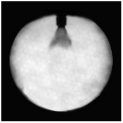 | 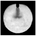 | 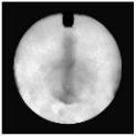 | 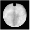 |
| Calculation |  |  |  |  |
Publisher’s Note: MDPI stays neutral with regard to jurisdictional claims in published maps and institutional affiliations. |
© 2022 by the authors. Licensee MDPI, Basel, Switzerland. This article is an open access article distributed under the terms and conditions of the Creative Commons Attribution (CC BY) license (https://creativecommons.org/licenses/by/4.0/).
Share and Cite
Liu, R.; Huang, K.; Qiao, Y.; Ji, H.; Zhong, L.; Wu, H. Effects of Low Pressure Injection on Fuel Atomization and Mixture Formation for Heavy Fuel Engines. Processes 2022, 10, 2276. https://doi.org/10.3390/pr10112276
Liu R, Huang K, Qiao Y, Ji H, Zhong L, Wu H. Effects of Low Pressure Injection on Fuel Atomization and Mixture Formation for Heavy Fuel Engines. Processes. 2022; 10(11):2276. https://doi.org/10.3390/pr10112276
Chicago/Turabian StyleLiu, Rui, Kaisheng Huang, Yuan Qiao, Haocheng Ji, Lingfeng Zhong, and Hao Wu. 2022. "Effects of Low Pressure Injection on Fuel Atomization and Mixture Formation for Heavy Fuel Engines" Processes 10, no. 11: 2276. https://doi.org/10.3390/pr10112276
APA StyleLiu, R., Huang, K., Qiao, Y., Ji, H., Zhong, L., & Wu, H. (2022). Effects of Low Pressure Injection on Fuel Atomization and Mixture Formation for Heavy Fuel Engines. Processes, 10(11), 2276. https://doi.org/10.3390/pr10112276