1. Introduction
There are several fields in precision machining methods, such as basic cutting methods, discharge and micro-thermal processing methods using lasers and water jets, and surface micromachining methods [
1,
2,
3]. Micromachining is a widely used and developed method in the field of semiconductor manufacturing [
4]. Based on micro-fluidics [
5,
6] technology, a variety of complex experiments have been performed by flowing fluid through a micro-channel. There is an urgent need for the production of fine structures such as high-tech ultra-precision devices, and particularly the fine processing of brittle materials such as ceramic is drawing attention. Recently, micro-abrasive jet blasting (μ-AJM) [
7,
8,
9,
10] has become one of the most attractive methods due to the shape processing condition using mechanical corrosion of brittle materials.
Particularly, the spray processing method using microparticles has been used for rust, painting, deburring and surface treatment and researched in the field of microfabrication and semiconductor manufacturing [
11]. Moreover, microparticle spraying has an advantage for mask fabrication using ceramic materials with low cost, reduced processing time, and less undercutting compared with chemical methods [
12,
13,
14,
15]. Many studies have been conducted using simple two-dimensional geometric shapes as the plane base material [
16,
17] and, in terms of aluminum alloy [
18,
19], materials for fine particle spraying.
In the industrial field, performance improvement through surface modification by coating metal or implanting metal elements with ions is required. In the case of aluminum thin-plate bonding, microparticles are first sprayed at high speed to provide adequate surface roughness throughout the plate, remove foreign substances and dust and apply a bonding agent, which is different from the existing chemical treatment method. It is possible to improve the working environment by preventing the occurrence of water pollution and fundamentally preventing water pollution caused by water treatment.
In this paper, an investigation of the optimal conditions for micro-abrasive jet blasting has been derived for the appropriate degree of roughness, considering variable parameters such as fine particle alumina, silicon carbide, nozzle diameter, pressure, injection height, and injection time with the dispersion analysis method used in the experimental design. Moreover, to improve the adhesion strength of aluminum materials, a measurement system has been used for surface roughness, with the maximum depth, diameter, and width evaluated.
2. Materials and Methods
The process of μ-AJM is a particle spraying process that mechanically removes material by controlled erosion, including drilling, grooving, or part milling. The method is strong enough to cut a hole in a ceramic substrate and is sufficient to cut a slot in a fragile silicon and glass wafer. It has no impact without generating heat or vibration. The processed particles are accelerated toward the specimen by compressed air or gas at high pressure, and fine particles of several µm to several tens of µm are supplied by the accelerated air or gas and a vibrating feeder, which is a constant-amount supply device, and are mixed in the nozzle. The particles are then sprayed at high speed through the nozzle. The sprayed particles are subjected to micromachining while hitting the specimen at a speed of 80 to 200 m/s, which is basically a method of mechanical etching.
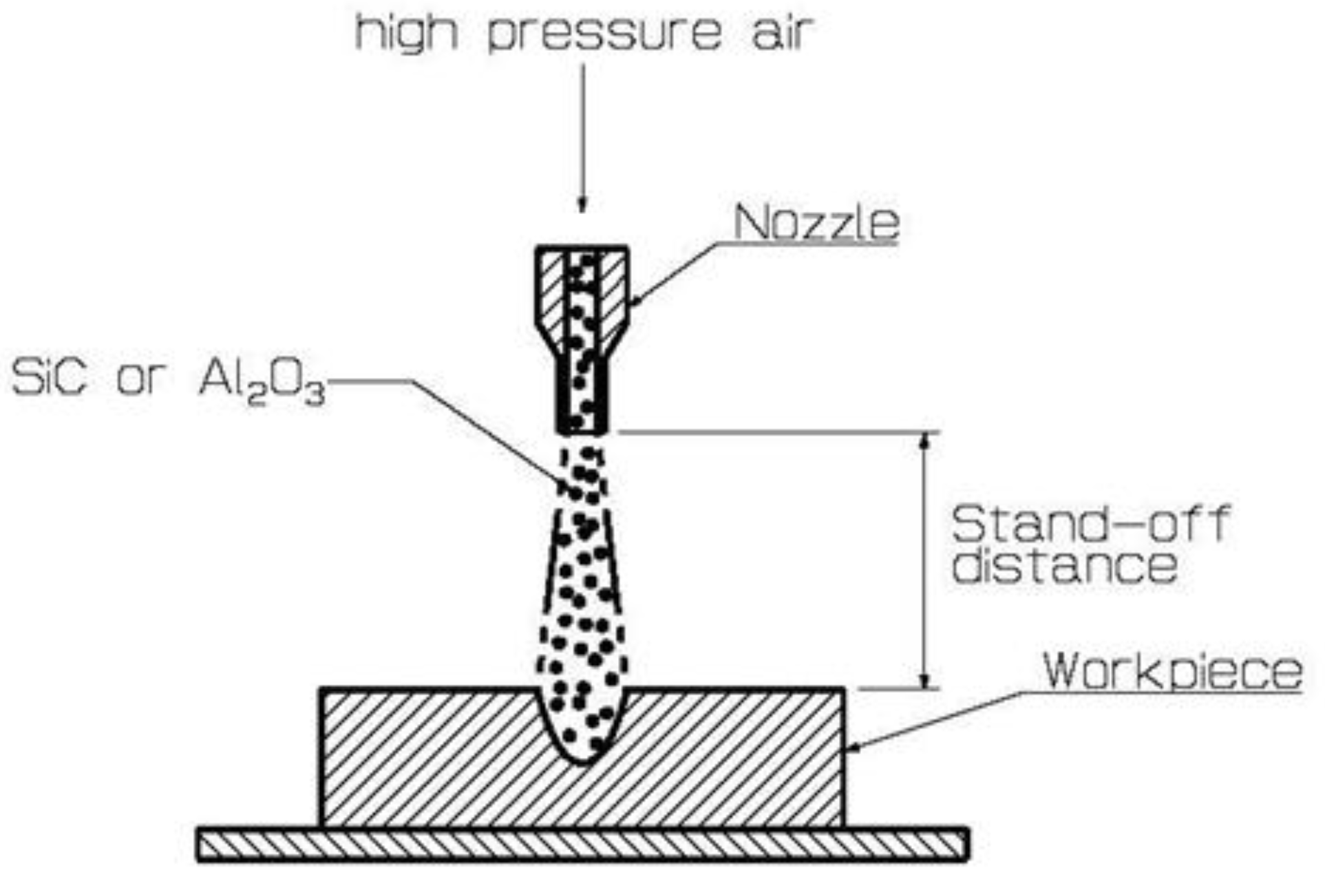
Figure 1 shows the basic processing principle of particle spraying, and the workpiece is processed by front and rear or left and right scanning of the nozzle.
3. Experiments
The statistical approach to designing and analyzing experiments consists of a measurement system for data acquisition, and the select analysis method is a prerequisite. The orthogonal arrangement table was applied to the experiments’ designs due to the large number of factors. The method detects the effect of the interaction between two factors that are expected to be effective in terms of main effects and technical aspects and reduces the number of experiments at the expense of information between two factors that do not occur.
3.1. Micro-Abrasive Jet Blaster
The equipment used to process the fine particles is shown in
Figure 2. A dual tank micro blaster (MB1006, COMCO INC, Burbank, CA, USA) manufactured by COMCO was used, and a dust absorber was attached to remove dust generated during the processing experiment. An air dryer was used to remove moisture from the fine microparticles and keep the system dry. The spray nozzle is a device for spraying particles onto a specimen. The difference in the diameter of the spray nozzle was expected to be a major factor in the change in surface properties. Therefore, the diameters of the spray nozzles were selected in sizes of 0.46, 0.7, 1.16, and 1.5 mm, respectively, and the experiment was conducted.
3.2. Blasting Movement System
In the case of a square specimen, a jig for fixing the specimen was prepared and tested by fixing it on the floor using a magnetic block. To fix and spray the square specimen, the center of the injection nozzle and the spray surface of the specimen were precisely matched vertically, and a guide for fixing the specimen and fixing the injection nozzle was separately manufactured and tested for adjustment of the injection distance.
Nevertheless, for cylindrical specimen experiments, a jig for spray processing was directly manufactured and used to fix the specimen and the spray nozzle, to adjust the accuracy of the spray distance, to adjust the spray height of the spray nozzle, and to control the speed of transport and rotation of the specimen.
Figure 3 is a schematic diagram of the operating system (a) and a precision particle spray processing system (b). This device enables precise fixation of the specimen and constant adjustment of the spraying distance for fine particle injection processing, and when rotating and testing a cylindrical specimen on a rotating shaft using two DC motors, the rotational speed of the specimen and the front-rear feed rate. A motor-driven stage was manufactured and used so that it could be variably adjusted.
The spraying method was to connect the hoses to the two spraying particle reservoirs to spray the spraying particles used in the experiment, respectively, when the dried air came out of the air drier. In this case, the injection particles used were SiC and Al2O3, and the injection material valve was injected in a predetermined amount through sequence control. The cylindrical specimen rotation conveying device has the function to precisely rotate and linearly feed the material using two motors and the microcontroller ATmega128. The experimental apparatus is largely composed of a mechanism that oversees rotation and linear transportation of the material and a control unit that controls the motor.
The control unit includes a potentiometer capable of inputting a continuous value, a button, and an LCD device capable of grasping the operation state of the experimental device so that the experimenter can operate intuitively. For the efficient operation of the experimental device, it displays the operating state of the device itself, so it does not need an external separate measuring instrument to understand the state, and the power supply has a built-in power conversion device, so only 220 V general power is required, and a separate external power supply is not required.
4. Experimental Results
The experiment was performed by applying the main factors and the spraying conditions obtained from the pre-tested rectangular specimen to the cylindrical specimen. The effect of the main factors on the cylindrical specimen is examined through the experiment results. Based on the conditions shown in
Table 1, the depth of the injection and the width of the injection were determined through a contact-type three-dimensional shape measuring device. Moreover, as experimental factors, A as spray particle, B as nozzle diameter, and C as pressure are specified as three variable values, and D as spray height and E as spray time are designated as fixed values.
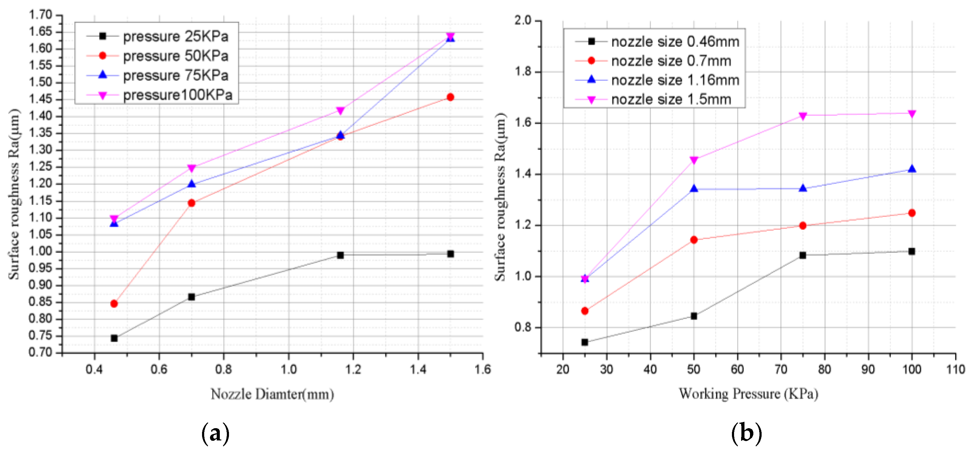
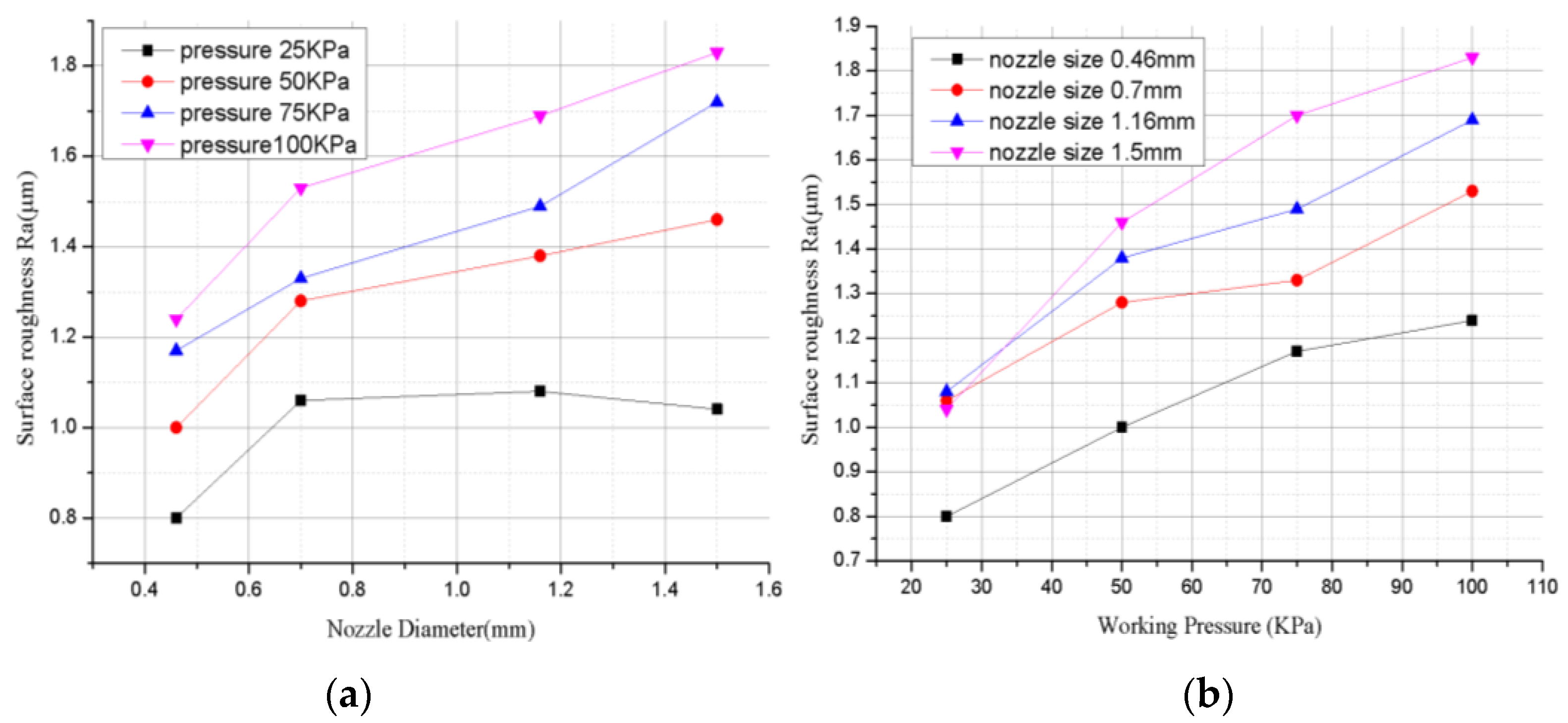
The surface roughness Ra value of the specimen subjected to the spiral surface spraying was measured through a surface roughness tester, and the result values are graphically displayed. The graph is summarized for each spray particle, and the graph is displayed based on the nozzle diameter and injection pressure.
Figure 4 shows the experimental results of surface roughness Ra for SiC as the spray particle. The results show that as the size of the nozzle diameter increases, the surface roughness Ra value increases slightly, and Ra decreased when the nozzle diameter was 1.16 mm and the pressure was 100.
The results of surface roughness Ra with Al
2O
3 used as the spray particles are shown in
Figure 5. The value for Ra slightly decreases at a nozzle diameter of 1.5 mm and at 25 kPa. The Ra value increases as the nozzle diameter increases. According to the results, the surface roughness Ra values of 0.7 mm, 1.16 mm and 1.5 mm were measured without a significant difference at 25 kPa, and the difference was due to the increase in the surface roughness as the injection pressure increased. In addition, in the graph, the surface roughness increases as the injection pressure increases. As shown in the graph of the spray particle SiC, the surface roughness Ra value increases as the nozzle diameter and injection pressure increase.
Figure 6 shows the increased surface roughness according to increasing injection pressure using the SEM (scanning electron microscope) on the nozzle diameter measuring 1.5 mm, with the working pressure increased from 25 to 100 kPa at 25 kPa increments. Nevertheless, the result shows a tendency for roughness extension and a considerably appropriate amount of roughness for each machining process.
Table 2 shows that the P value for the injected particles is 0, the P value for the nozzle diameter is 0.000, and the P value for the injection pressure is 0.000. In case of the P value being less than 0.05, the result is determined as significant. Moreover, for the contributions of factors affecting the surface roughness Ra, the contribution from the spray particles was 7.14%, the nozzle diameter was 29.55% and the injection pressure was 56.53%. When comparing the influences on the surface roughness Ra through contributions, it is judged that the influences are high and in the order of injection pressure, nozzle diameter, and injection particles.
5. Conclusions
In this study, an investigation of the main parameters of processing, such as fine particle alumina, silicon carbide, nozzle diameter, pressure, injection height, and injection time, has been researched through the dispersion analysis method in the experimental design. According to the experiments’ results, the main factors influencing each item were found to determine the contribution. The injection depth was 16.74% for the spray particles, 18.52% for the nozzle diameter, and 31.78% for the spray pressure. The spray diameter was 21.05% for the spray particles, 29.36% for the nozzle diameter, and 40.50% for the spray pressure. In addition, the surface roughness Ra was 21.05% for the spray particles, 29.36% for the nozzle diameter, and 40.50% for the spray pressure.
According to the main contributions for the cylindrical surface micro-blasting experiment, the influences on the injection depth, the injection diameter, and the surface roughness (Ra) were determined to be high and in the order of the injection pressure, the nozzle diameter, and the spray particles. As a result of the analysis, it was found that the impact level was high when the injection particle level was one SiC, the nozzle diameter was three and four (1.16 and 1.5 mm), and the injection pressure was at level four (100 kPa).
In conclusion, the method for generating the required roughness on an aluminum surface using these research results can improve environmental pollution and the working environment, unlike the conventional chemical treatment method for improving product reliability and reducing manufacturing costs. (KR. Patent No. 10-1533555).


