Abstract
To simultaneously satisfy the electricity and freshwater requirements, a superstructure of a solar-wind-diesel hybrid energy system (HES) with multiple types of storage devices driving a reverse osmosis desalination (ROD) process is established in this paper. The corresponding mathematical model of the HES, potentially including photovoltaic cells, a wind turbine, a diesel generator, a ROD unit, different battery storage technologies, or a water tank is developed and features mixed integer linear programming. The optimum design and operation schemes of the HES can be obtained by taking the minimum total annual cost as the optimization objective. To verify the effectiveness of the proposed method, an example of a solar-wind-diesel system for supplying a ROD process in Saudi Arabia is adopted. The results show that a photovoltaic panel, wind turbine, diesel generator, lead-acid battery, Li-ion battery and water tank are selected in the HES with the minimum total annual cost (i.e., 1.16 × 10⁵ USD·y−1), by satisfying the requirement of the renewable energy penetration rate (i.e., 0.8). Then, a quantified method is proposed to determine the optimal design and operation schemes of the HES, including both economic and environmental aspects. Finally, the HES with various generators and multiple types of storage devices shows a better performance in terms of economy and renewable energy utilization.
1. Introduction
Energy resources and freshwater are important foundations for people to live and work, and are indispensable for the functioning of the global economic system [1,2]. With the rapid development of industrialization and living standards across the globe, energy and freshwater security become challenging issues for all the countries. Currently, the implementation of reverse osmosis desalination (ROD) plants driven by the renewable energy sources shows a promising opportunity to deal with the energy and freshwater problems [3,4,5]. In addition, the utilization of renewable energy sources, such as solar and wind, has increased tremendously and offered a potential option to address the problem of global warming and greenhouse gas emissions, due to its clean and recyclable features [6,7]. Thus, it is an effective approach to utilizing renewable energy sources for powering a ROD unit.
The variable fluctuations in renewable energy sources make it difficult for them to provide stable or constant power for the ROD unit, which may not satisfy the energy requirements of the electricity load and ROD unit [8,9,10]. These things considered, the changes in the electricity demand and freshwater requirement also harness the development of the renewable energy to drive the ROD system [11,12].
To address the abovementioned crisis, the utilization of the hybrid energy systems (HESs), which could be composed of one or more renewable energy source, an optional energy storage system, and/or other backup devices to power the ROD unit, exhibits many advantages in economic efficiency and operating performance [13,14]. Of course, it can optimize the design of the ROD unit by accommodating the variations of supply and demand [15,16]. From the perspective of the supply side, the combination of renewable energy sources, such as solar and wind energy sources, is an effective approach to supply electricity and freshwater for the loads [17,18,19]. Ghaithan et al. [20] proposed a grid-connected hybrid solar-wind system to power a ROD unit with the aim to obtain an optimal design. Maleki et al. [21] constructed and designed a hybrid photovoltaic-wind-hydrogen-ROD system to simultaneously meet the life cycle cost of the economic evaluation and the loss of power supply probability. Occasionally the diesel generator could be selected to be a backup device for the HES to power the ROD unit [22], especially in a remote area. In addition, a diesel generator offers an advantage in operating and can flexibly change its output power to an extent [23]. Wu et al. [24] developed and optimized a standalone ROD system driven by a photovoltaic, battery, and diesel generator hybrid system for increasing freshwater availability and meeting the electrical load demand. To further increase the potential system efficiency, economy, and reliability, an energy storage system—a flexible device for absorbing and releasing power, ignoring the time and space restrictions to an extent—was integrated with the ROD unit to adjust the electricity and freshwater demand characteristics to alleviate the mismatches of electricity and freshwater between the supply and demand sides [25,26,27]. Spyrou and Anagnostopoulos [28] investigated the optimum design and operation of a standalone desalination system powered by renewable energy sources and adopted a pumped storage unit to guarantee the desired freshwater production. Smaoui et al. [29] studied the optimal sizing method of a hybrid photovoltaic/wind system with a hydrogen storage system to feed the freshwater demand. From the abovementioned analysis, it can be known that, to obtain a better performance of the system, there needs a flexible method to select the components to construct the HES for supplying the ROD process. Thus, for the design and optimization of the HES to drive ROD processes, there is extensive research devoted to finding an efficient solution strategy for the corresponding mathematical model [21,30]; however, most of the abovementioned studies investigated the HES for powering a ROD unit based on one or several fixed-system structures, and somehow, they ignored the effects of the different system structures on the performance of the whole system. Therefore, it is significantly important to develop a unified method to establish a mathematical model for constructing the corresponding HES and investigate the design characteristics of the HES, from the perspectives of supply and storage sides.
Energy storage systems play a vital role in the HES for powering ROD processes. The battery, as an efficient electricity storage device, gains a great deal of attention for integration with in the HES [31,32]. Gökçek [33] integrated the lead-acid battery into the wind-photovoltaic-diesel hybrid power system to supply the seawater reverse osmosis system for small-scale desalination applications. Different types of batteries pose distinct performance characteristics, which will affect the design and operation of the HES [34]. To determine the best battery storage technology in the desalination plant, different types of batteries with various depths of discharge are respectively investigated in the system [35]; however, these studies are mostly focused on the design and operation optimization of the battery energy storage system and fail to take battery degradation and various battery types into consideration. Different from the common HES, there are two types of energy forms, including electricity and water in the system; thus, a battery energy storage system and water tank are usually configured in the HES [36]. Das et al. [19] investigated an HES with solar photovoltaic cells, a wind turbine, a diesel generator, a battery and a water tank to meet the electricity and freshwater demands. Even though the design optimization of this study has been carried out, the electricity balance is only considered, and the water balance is somehow ignored. In addition, the effects of the battery bank and water tank on the optimal design of the HES for powering a ROD unit and the relationship between the battery bank and water tank are usually not investigated.
To this end, a superstructure and corresponding mathematical optimization model of an HES with multiple types of storage devices for supplying the ROD unit is constructed in this paper, which is a mixed linear programming model. The remaining is organized as follows: The problem statement is presented in Section 2. Then, a mathematical optimization model of the HES with multiple types of storage devices for supplying ROD units is constructed in Section 3. Subsequently, a case study of an HES is adopted in Section 4. Finally, Section 5 gives the conclusions.
2. Problem Statement
Figure 1 gives a schematic of an HES with multiple types of storage devices driving a ROD process. In Figure 1, the renewable energy generation system, including a photovoltaic panel, a wind turbine, and a diesel generator are used to supply power for the load and ROD unit. The storage system in this HES may contain two types of energy forms, i.e., electricity and freshwater. For the electricity, the battery bank with various battery technologies is adopted, and water tank is used to buffer the mismatches between the freshwater supply and demand. For the load of the system, electricity and freshwater requirements should be satisfied simultaneously in this work, on the premise of meeting the renewable energy penetration requirement of the proposed system.
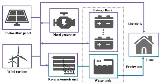
Figure 1.
A schematic of an HES with multiple types of storage devices driving a ROD process.
In this work, the optimization problem for the HES with multiple types of storage devices for supplying the ROD unit can be described as follows: Given are (1) the power curves of a photovoltaic panel and wind turbine with per capacity, (2) technical and economic parameters of each component, and (3) the electricity and freshwater requirements.
In order to minimize the total cost of the system, the main goal of this work is to obtain the optimal design and operating schemes and investigate the configuring characteristics of the HES with multiple types of storage devices for supplying the ROD unit.
3. Mathematical Model of the HES with Multiple Types of Storage Devices for Supplying ROD Unit
In this section, the objective function and corresponding constraints of the mathematical model of an HES with multiple types of storage devices to drive a ROD unit are described in detail.
3.1. Objective
In this work, the minimum total annual cost of the HES with multiple types of storage devices driving the ROD unit is adopted as an optimization objective, which can be written as
where , and indicate the total annual cost, investment cost, and operating cost, respectively.
The investment cost depends on the rated capacity, unit cost, and capital recovery factor of specific component in the system, which can be described as
where superscripts , wt, , , b, , , , and represent photovoltaic panel, wind turbine, diesel generator, battery bank, ROD unit, water tank, energy capacity, and power capacity, respectively. , , and stand for the rated power capacity, rated energy capacity, unit cost, and capital recovery factor of specific component in the system. The superscript i stands for each component in the HES. The subscript stands for a certain battery, and the set N represents all batteries.
The operating cost is composed of the operational and maintenance (O&M) cost, , and other cost, , which can be written as
The O&M cost can be calculated as
The other cost mainly refers to the sum of the chemical cost, , and the membrane replacement cost, , of the ROD unit and fuel cost of diesel generator, which can be expressed as
where is the fuel consumption of the diesel generator at time interval k in day d. is the elapsed time of time interval k in day d. Sets K and D represent time intervals and days of the time horizon in the system.
The capital recovery factor can be written as
where represents the lifetime of component. stands for the O&M coefficient corresponding to each specific component. is the interest rate. It should be noted that the lifetimes of each component and whole system are presumed values in this work.
3.2. Constraints
3.2.1. Renewable Generation System
The output power of the renewable energy sources in this work is the sum of the output power of the photovoltaic panel and that of the wind turbine. In addition, the output power of photovoltaic panel and wind turbine can be calculated by their corresponding rated power and capacity factors. Therefore, the output power of renewable energy sources could be described as
where is the output power of the renewable generation system at time interval k in day d. and represent the capacity factors of the photovoltaic panel and wind turbine at time interval k in day d.
The existences of the photovoltaic panel and the wind turbine in the HES can be written as
where and are binary variables. When , a photovoltaic panel is selected in the HES. When , the wind turbine system is adopted in the HES. and stand for the minimum and maximum rated power of photovoltaic panel, respectively. and stand for the minimum and maximum rated power of wind turbine system, respectively.
The power generated by the renewable energy sources can be used for the ROD unit, the electricity load, and the battery bank. It can be described as
where , , and stand for the power from the renewable energy generation system to the ROD unit, electricity load, and battery bank at time interval k in day d, respectively.
To satisfy the renewable energy utilization requirement of the system, the renewable energy penetration rate should be not lower than the allowed value of the system, which can be expressed as
where is the allowed value of the renewable energy penetration rate, which is presumed. Of course, this value can be also optimized in the proposed method.
3.2.2. Diesel Generator
The output power of the diesel generator can be written as
where is the output power of the diesel generator at time interval k in day d. a and b are the intercept coefficient of the fuel curve and the slope of the fuel curve, respectively.
The constraints of the diesel generator rated power can be expressed as
where is a binary variable. When , the diesel generator is selected in the HES. and stand for the minimum and maximum rated power of the diesel generator, respectively.
The power generated by the diesel generator can be described as
where , and represent the power from the diesel generator to the ROD unit, electricity load, and battery bank at time interval k in day d, respectively.
The operating constraints of the diesel generator can be expressed as
where and are the operating coefficients of the diesel generator. is a binary variable to index the operating state of the diesel generator at time interval k in day d.
3.2.3. Battery Bank
The electricity balance of each battery can be expressed as
where is the electricity of the battery n at time interval k in day d. and are the charging and discharging power of the battery n. and are the charging and discharging efficiencies of the battery n.
For the battery bank and each battery, the charging and discharging power can be expressed as
where and are the power from the battery bank to the ROD unit and electricity load at time interval k in day d, respectively.
In this work, the battery degradation characteristic is taken into considered, which can be described as
where is the battery capacity degradation rate.
The charging and discharging states of the battery bank, electricity constraints, state-of-charge constraints, and other constraints can refer to the literature [37].
3.2.4. Water Tank
A water tank is used to buffer the demand and supply of freshwater. The water balance can be expressed as
where is the water content of the water tank at time interval k in day d. and are the inlet and outlet water flow rates at time interval k in day d, respectively.
The inlet and outlet flow rates can be written as
where and are the water-generation flow rates of the ROD unit and the freshwater demand at time interval k in day d.
The existence of the water tank can be described as
where is a binary variable to index the existence of the water tank in the HES. and are the minimum and maximum rate capacities of the water tank.
The content constraints of the water tank can be expressed as
where and are the operating coefficients of the water tank.
3.2.5. Reserve Osmosis Desalination Unit
The electric power for desalination and the hourly water demand are correlated based on the average desalination specific energy consumption and hourly volumetric water demand. The power required by the ROD unit can be expressed as
where is the power required of the ROD unit. is the power required of the ROD unit for 1 m3. and are the operating coefficients of the ROD unit.
3.2.6. Demand Side
The electricity demand of this system can be supplied by the renewable generation system, diesel generator, and battery bank, which can be written as
where is the electricity demand of the load at time interval k in day d.
The freshwater demand is described in Equation (25).
The abovementioned is the proposed mathematical model of the HES with multiple types of storage devices for supplying the ROD unit, which features a mixed integer linear programming problem. By addressing this proposed mathematical model, the optimal design and operation schemes of the HES can be determined. There are still some limitations of the proposed model. The first limitation, owing to the focus on the optimization of the HES in this work, is that the mathematical model of the ROD unit is relatively simple. The second limitation is that the generation process of the renewable energy should also be considered. Fortunately, these two problems can be effectively addressed by extending the proposed model.
4. Case Study
To verify the effectiveness of the proposed method, an example of a solar-wind-diesel HES with multiple types of storage devices for supplying the ROD process in Saudi Arabia is adopted. The optimal configuration and operating schemes can be obtained by targeting the minimum total annual cost of the HES. In addition, the effects of the different system structures on the performance of the whole system and the configuring mechanism of the HES are comprehensively investigated in this work.
4.1. Fundamental Data
In this work, for the supply side, there are three power-generation systems, namely a photovoltaic panel, a wind turbine, and a diesel generator. For the storage side, two types of energy storage devices are included in the HES. The first one is a battery bank, which could be composed of lead-acid, Li-ion, and NaS batteries. The second one is a water tank, which is used as the freshwater buffering tank for the system.
For the HES with multiple types of storage devices to supply the ROD unit, regular days of each month are selected to illustrate the variabilities of the renewable generation systems, and the capacity factors of the photovoltaic panel and the wind turbine are given in Figure 2. In this work, the freshwater and electricity requirements of each month are assumed to be equal, which can be seen in Figure 3. The primary parameters of photovoltaic panel, wind turbine, diesel generator, battery bank, ROD unit, and water tank are listed in Table 1. The lifespan of the system is 20 years and the interest rate is 10% in this case study. For the diesel generator, the coefficients a and b are set to 0.08145 L·kWh−1 and 0.246 L·kWh−1, the operating power is set between the 30% and 90% of its rated capacity, and the fuel price is 0.75 USD·L−1 [30]. For the ROD unit, the membrane replacement and chemical costs are 0.06 USD·m−3, the number of membrane replacements per year is two, and 1 m3 freshwater requires 4 kWh of electricity [36]. The operating power of the ROD unit should be greater than 25% of its rated capacity [38]. For the storage side, the efficiency, lifetime cycle, and state-of-charge limits of each battery can be referred to in the literature [39]. It should be noted that this paper is focused on the optimization of the HES, thus the detailed design of the ROD unit is not considered.
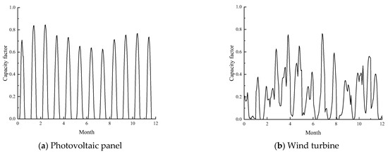
Figure 2.
Capacity factors of the photovoltaic panel and the wind turbine.
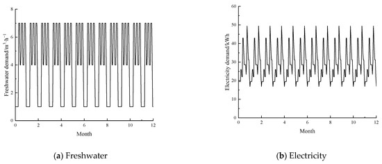
Figure 3.
Freshwater and electricity requirements of the system.

Table 1.
Parameters of the system.
All calculations in this work were carried out on the GAMS platform, with the CPU of Intel(R) Core(TM) i5-10210U@1.6GHz. CPLEX was selected as the solver for the mixed integer programming problems. In this example, all solutions are optimal.
4.2. Optimal Configuration and Operation of HES with Multiple Types of Storage Devices Driving ROD Unit
In this case study, the lowest allowable value of the renewable energy penetration rate is 0.8 of the HES. By solving the proposed mathematical optimization model, the minimum total annual cost and the corresponding capacity configuration scheme of the HES with multiple types of storage devices for supplying the ROD unit can be obtained. The optimal results with the minimum total annual cost of the HES are listed in Table 2, and the cost composition of the system is described in Figure 4.
Table 2.
Optimal results of the system.
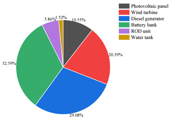
Figure 4.
Cost compositions of the system.
By addressing the mathematical model of the HES with multiple types of storage devices to power the ROD process, the lowest total annual cost of the system is 1.16 × 10⁵ USD·y−1, when the renewable energy penetration rate equals 0.8 and the photovoltaic panel, wind turbine, diesel generator, battery bank, and water tank are all selected in the system. This indicates that the system with various components exhibits better economic performance.
For the renewable generation side, the capacity of wind turbines is greater than that of photovoltaic panels, which can be obtained by analyzing and comparing the characteristics of supply and demand curves. In addition, the average capacity factor of the wind turbine is relatively greater than that of the photovoltaic panel, which can be obtained from Figure 2 and Figure 3.
For the storage side, two types of storage devices, including a battery bank and a water tank, are chosen in this example. For the battery bank in this case study, lead-acid batteries and Li-ion batteries are chosen, which depends on the trade-off between the capital cost and operating performance, such as degradation characteristics, efficiency, and SOC allowable ranges. The selection of the two types of batteries and water tank implies that the storage system with different storage forms is superior in the HES for supplying the ROD process.
Figure 4 shows the cost compositions of the HES with multiple types of storage devices to power the ROD unit, where the costs of the system include the cost of each component. It can be seen in Figure 4 that the cost of the energy supply side accounts for 60.02%, while the cost of the storage side accounts for 34.12%. For the renewable energy generation, the cost of wind turbines has a relatively large proportion, 20.39%, while the cost proportion of photovoltaic panels is only 10.55%. This demonstrates that wind turbines are superior to photovoltaic panels in the proposed system. The cost proportion of the diesel generator is the second largest, 37.84%, because of its flexible output-power characteristics and relatively lower capital and operating costs, which can be referred in Table 1 and Section 3.2.2. For the storage system, the cost of the battery bank has the largest proportion, 32.59%, and this implies that the battery bank plays a vital role in keeping the balance of the supply side and demand.
The optimal solution for the HES with multiple types of storage devices driving the ROD unit is determined by targeting the minimum total annual cost, based on the premise of satisfying the requirement of the renewable energy penetration rate (i.e., 0.8 in this example). To give a comprehensive guideline for the designer or the user for selecting the most suitable solution of the HES, the variations of total minimum annual cost with renewable energy penetration rate are summarized. In order to evaluate the proposed system from the environmental aspect, the carbon dioxide emission of the system is evaluated. In this HES, the primary carbon dioxide emission is generated by the diesel generator, which is driven by fuel. The relationship between the fuel consumption and carbon dioxide emissions of the diesel generator can be referred to in the literature [41]. Figure 5 shows variations of the total annual cost and the carbon dioxide emissions with the renewable energy penetration rate. It should be noted that, in Figure 5b, TAC and CO2 represent the total annual cost and carbon dioxide emissions, respectively.
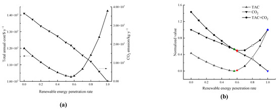
Figure 5.
Variations of total annual cost and carbon dioxide emissions of the HES with renewable energy penetration rate. (a) Variations of the total annual cost and carbon dioxide emissions with renewable energy penetration rate, (b) Variations of normalized total annual cost and normalized carbon dioxide emissions with renewable energy penetration rate.
According to Figure 5a, the total annual cost shows a downward trend at first, but then increases with the increase of the renewable energy penetration rate. When the value of the renewable energy penetration rate is 0.562 (hollow dots in Figure 5b), the total annual cost of the HES is at its lowest. This is also the globally optimal solution in this work, when the economic goal is targeted by not limiting the requirement of the renewable energy penetration rate. For the environmental aspect, the carbon dioxide emissions decrease as the penetration rate of the renewable energy increases. In this paper, carbon dioxide emissions are mainly due to the burning of diesel fuels, and the relationship between the carbon dioxide emissions and the diesel fuel can be regarded as linear [41]. As the penetration rate of renewable energy increases, the power supplied by the diesel generator also decreases, which corresponds with a decrease in carbon dioxide emissions. It also can be concluded that the carbon dioxide emission and the renewable energy penetration rate are almost linear in Figure 5a. It should be noted that carbon dioxide emissions are not the only environmental influence, as other gas emissions (such as sulfur dioxide and nitrogen oxide) will also be also produced; however the carbon dioxide emission is primary, and the relationships between the other gas emissions and the diesel fuel are also linear. Thus, when considering other gas emissions, the optimal results are almost not affected.
Even though the total annual cost of the HES is taken as the only optimal target in this work, the environmental assessment can also helpfully be used to evaluate the configuration and performance. To obtain the optimal configuration of the HES under the economic and environmental assessments, corresponding normalized valves of the total annual cost and carbon dioxide emissions are given in Figure 5b. It can be obtained that when the total annual cost is taken as the main optimization objective, the solution corresponding to the 0.562 renewable energy penetration rate is the optimal solution (dots marked green in Figure 5b). When the proposed system pays more attention to the environmental influence, the lowest carbon dioxide emission with a renewable energy penetration rate of 1 is the optimal solution (dots marked blue in Figure 5b). In order to simultaneously minimize the total annual cost and carbon dioxide emissions, the HES with a 0.6 renewable energy penetration rate is optimal (dots marked red in Figure 5b). In all, Figure 5 provides a guideline for designers to configure the HES with multiple types of storage devices for powering the ROD unit by simultaneously taking the economic and environmental targets into consideration. In other words, a quantified method is proposed to determine the optimal design and operation schemes of the HES, given the economic and environmental aspects.
By solving the proposed mathematical model, the operating scheme of the HES with multiple types of storage devices for powering the ROD unit with the lowest total annual cost can also be obtained by satisfying requirement of the renewable energy penetration rate (namely 0.8 in this example). The power scheduling schemes of the electricity load and the ROD unit at the first month are taken as examples to illustrate the operating scheme of the proposed system, as shown in Figure 6.
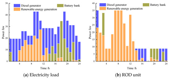
Figure 6.
Operating schemes of the electricity load and the ROD unit.
In Figure 6, it can be seen that the electricity load is mainly supplied by the diesel generator, while the requirement of the ROD unit is primarily satisfied by the renewable energy generation. From the operating schemes in Figure 6, it can be obtained that the diesel generator is used to frequently adjust the power characteristics to satisfy the demand of the electricity load and the ROD unit due to the flexibility in operation. This is the reason for the high cost proportion of the diesel generator in the system. Compared with the diesel generator, the battery bank is also frequently discharged to supply electricity. It should be noted that, the power curve of the ROD is not consistent with that corresponding with the freshwater demand. The differences between these power curves are compensated by the water tank, which implies that the water tank can be partially replaced by the battery bank to balance the supply and demand sides in the HES.
4.3. Composition Characteristics of the HES with Multiple Types of Storage Devices for Supplying ROD Unit
In this section, the composition characteristics of the HES with multiple types of storage devices for supplying the ROD unit are comprehensively analyzed and compared from the supply and storage sides, respectively.
4.3.1. Supply Side
Figure 7 gives the variations of the total annual cost under different configurations, by considering the different combinations of components in supply side. In Figure 7, DG, PV and WT stand for diesel generator, photovoltaic panel and wind turbine.
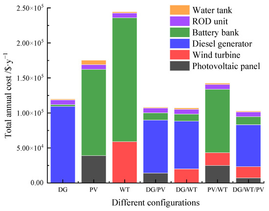
Figure 7.
The variations of the total annual cost under different configurations in supply side.
In Figure 7, the highest total annual cost of the system is the one only with wind turbine in the supply side. In this system, the cost of wind turbine and battery tank account for the largest proportion. It implies that the power curve of the wind turbine is quite different from the power curves of the electricity load and freshwater demand. Thus, there needs to be a large-capacity battery bank in the system to realize the energy balance of the wind turbine and demand side, which also results in a higher cost of the system. From Figure 7, the system with a diesel generator, wind turbine and photovoltaic panel has the minimum total annual cost. This implies that the output power characteristics of a diesel generator, wind turbine and photovoltaic panel are somewhat complementary, which can reduce the configured capacity of the storage system, including the battery bank and water tank, and achieve a better economic performance.
In Figure 7, for the only type of generator in the system, the total annual cost order of the HES is DG < PV < WT, which mainly depends on the differences between the supply and demand sides. Owing to the flexibility of the diesel generator in operation, the HES only with the diesel generator has the lowest total annual cost.
When taking two types of generators into account, the total annual costs of these systems is only DG/WT < DG/PV < PV/WT. The costs of the HES with two types of generators are lower than those with only one type generator, which indicates that two distinct generators have some complementary characteristics in the design and operation optimization of the system to achieve a lower total annual cost. It can be also found that the cost of the HES with photovoltaic panels and a wind turbine is higher than that of two other ones, which also implies the advantage of the diesel generator in the HES.
Considering all types of generators, it can be seen that the corresponding HES has the lowest total annual cost. By comparing the HESs with the diesel generator, namely DG, DG/PV, and DG/WT, the HES with all types of generators shows a low dependence on the diesel generator, which also indicates a higher renewable energy penetration rate.
Based on the abovementioned analysis and discussion, for driving the ROD unit, the HES with the diesel generator, wind turbine and photovoltaic panels shows the best economic performance, by comparing the systems with different configurations in the supply side.
4.3.2. Storage Side
According to the previous analysis and discussion, it can be seen that the cost proportion of a storage system including a battery bank and water tank is relatively large compared the other components. Thus, the effects of the storage system on the HES are comprehensively studied in this section. In order to demonstrate the effects and advantages of the storage system with multiple types of devices, the capacity designs of the system with various types of energy forms are analyzed and compared, when the lowest total annual cost of the HES is taken as the optimal target. The capacity configurations, the total annual costs, and the renewable energy penetration rates are summarized in Table 3. In Table 3, four scenarios are defined. The system with a battery bank and water tank are in scenario S1, the system with only a battery bank is in scenario S2, the system only with a water tank is in scenario S3, and the system without any storage device is in scenario S4.
Table 3.
Optimal results under different scenarios.
In Table 3, by comparing the HESs with storage devices in S1 and without storage devices in S4, it can be concluded that the total annual cost of the system in S1 is about 20% lower than that in S4. In addition, the renewable energy penetration rate of the system in S1 is significantly larger than in S4; moreover, the total annual cost of any system with a storage device is lower than that without a storage device, while the renewable energy penetration rate of any system with a storage device is greater than that without a storage device. This indicates that the integration of a storage system in the HES can improve the economy and renewable energy utilization rate simultaneously. In this example, by comparing S2 and S3, it can be seen that it is more effective to adopt a water tank as a storage device to increase economy, while the battery bank is superior to increase the renewable energy penetration rate. This implies that the combination of a battery bank and a water tank can achieve a better operating performance (including economic and renewable energy penetration rate) for the whole system, which is also verified by the results of S1 in Table 3.
5. Conclusions
In this work, taking the minimum total annual cost as the optimization target, a superstructure and corresponding mathematical model of the HES with multiple types of storage devices driving the ROD unit was developed, aiming to simultaneously satisfy the electricity and freshwater requirements. To verify the effectiveness of the proposed method, an example of a solar-wind-diesel system for supplying the ROD processes in Saudi Arabia was adopted. By solving the proposed mathematical model, the optimal design and operation schemes of the HES could be obtained simultaneously. When the minimum total annual cost is the objective, a photovoltaic panel, wind turbine, diesel generator, lead-acid battery, Li-ion battery, and water tank are used in the HES, with an allowable renewable energy penetration rate of 0.8. In addition, by analyzing the variations of the normalized total annual cost and the normalized carbon dioxide emissions with the renewable energy penetration rate, the designer can obtain a proper system configuration by assessing the economic and environmental requirements. Furthermore, by comprehensively analyzing and comparing the composition characteristics of the HES from the supply and storage perspective, it can be proved that the HES with various generators and multiple types of storage devices shows a better performance in economy and renewable energy utilization.
For the integration of the HES with multiple types of storage for powering a ROD unit, the proposed mathematical model provides an effective tool to determine the optimal design and operation schemes. Based on this work, the effects of the inlet and outlet water salinities on the performance of the ROD unit and the configuration of the HES should be comprehensively investigated for practical applications. At the same time, a more accurate model to describe the operating characteristics of the ROD unit and an efficient solution for addressing the corresponding mathematical model should be taken into consideration. Of course, these issues deserve further efforts in the future.
Author Contributions
Conceptualization, Y.J.; methodology, Y.J., J.Z. and Z.T.; software, Y.J.; validation, Y.J.; formal analysis, Y.J. and J.Z.; investigation, Y.J.; resources, Y.J. and J.Z.; data curation, Y.J. and J.Z.; writing—original draft preparation, Y.J.; writing—review and editing, Y.J. and J.Z.; visualization, Y.J.; supervision, Y.J. and Z.T.; project administration, Y.J.; funding acquisition, Y.J. All authors have read and agreed to the published version of the manuscript.
Funding
The authors are grateful for financial support from the Dean Project of Guangxi Key Laboratory of Petrochemical Resource Processing and Process Intensification Technology (No. 2021Z017).
Institutional Review Board Statement
Not applicable.
Informed Consent Statement
Not applicable.
Data Availability Statement
Not applicable.
Conflicts of Interest
The authors declare no conflict of interest.
Nomenclature
| Sets | |
| D | A set of days |
| K | A set of time intervals |
| N | A set of batteries |
| Parameters | |
| a | Intercept coefficient of the fuel curve |
| b | Slope of the fuel curve |
| CRF | Capital recovery factor |
| F | Flow rate |
| f | O&M coefficient |
| L | Lifetime |
| r | Interest rate |
| Operating coefficient | |
| Renewable energy penetration rate | |
| Efficiency | |
| Capacity factor | |
| Fuel price | |
| Elapsed time | |
| Variables | |
| C | Cost |
| E | Energy |
| P | Power |
| z | Binary variable |
| Battery capacity degradation rate | |
| Superscripts | |
| b | Battery bank |
| bl | Battery bank to the electricity load |
| br | Battery bank to the reverse osmosis desalination unit |
| che | Chemical |
| dg | Diesel generator |
| dgb | Diesel generator to battery bank |
| dgl | Diesel generator to electricity load |
| dgro | Diesel generator to reverse osmosis desalination unit |
| E | Energy capacity |
| in | Inlet |
| inv | Investment |
| max | Maximum |
| mem | Membrane replacement |
| min | Minimum |
| O&M | Operational and Maintenance |
| on | Operating state |
| oper | Operating |
| other | Other |
| out | Outlet |
| P | Power capacity |
| pv | Photovoltaic panel |
| rated | Rated state |
| ro | Reverse osmosis unit |
| s | Renewable generation system |
| sb | Renewable energy generation system to battery bank |
| sl | Renewable energy generation system to electricity load |
| sro | Renewable energy generation system to reverse osmosis desalination unit |
| tac | Total annual cost |
| unit | Unit |
| w | Water tank |
| wt | Wind turbine |
| Subscripts | |
| d | Day |
| k | Time interval |
| n | Battery |
| Abbreviations | |
| HES | Hybrid energy system |
| ROD | Reverse osmosis desalination |
References
- Wang, S.; Wang, S. Implications of improving energy efficiency for water resources. Energy 2017, 140, 922–928. [Google Scholar] [CrossRef]
- Ke, J.; Khanna, N.; Zhou, N. Analysis of water–energy nexus and trends in support of the sustainable development goals: A study using longitudinal water–energy use data. J. Clean. Prod. 2022, 371, 133448. [Google Scholar] [CrossRef]
- Mito, M.T.; Ma, X.; Albuflasa, H.; Davies, P.A. Variable operation of a renewable energy-driven reverse osmosis system using model predictive control and variable recovery: Towards large-scale implementation. Desalination 2022, 532, 115715. [Google Scholar] [CrossRef]
- Zhao, P.; Gou, F.; Xu, W.; Wang, J.; Dai, Y. Multi-objective optimization of a renewable power supply system with underwater compressed air energy storage for seawater reverse osmosis under two different operation schemes. Renew. Energy 2022, 181, 71–90. [Google Scholar] [CrossRef]
- Bundschuh, J.; Kaczmarczyk, M.; Ghaffour, N.; Tomaszewska, B. State-of-the-art of renewable energy sources used in water desalination: Present and future prospects. Desalination 2021, 508, 115035. [Google Scholar] [CrossRef]
- Khan, M.A.M.; Rehman, S.; Al-Sulaiman, F.A. A hybrid renewable energy system as a potential energy source for water desalination using reverse osmosis: A review. Renew. Sustain. Energy Rev. 2018, 97, 456–477. [Google Scholar] [CrossRef]
- Mito, M.T.; Ma, X.; Albuflasa, H.; Davies, P.A. Reverse osmosis (RO) membrane desalination driven by wind and solar photovoltaic (PV) energy: State of the art and challenges for large-scale implementation. Renew. Sustain. Energy Rev. 2019, 112, 669–685. [Google Scholar] [CrossRef]
- Ruiz-García, A.; Nuez, I. Long-term intermittent operation of a full-scale BWRO desalination plant. Desalination 2020, 489, 114526. [Google Scholar] [CrossRef]
- Dimitriou, E.; Boutikos, P.; Mohamed, E.S.; Koziel, S.; Papadakis, G. Theoretical performance prediction of a reverse osmosis desalination membrane element under variable operating conditions. Desalination 2017, 419, 70–78. [Google Scholar] [CrossRef]
- Ruiz-García, A.; Nuez, I. Performance evaluation and boron rejection in a SWRO system under variable operating conditions. Comput. Chem. Eng. 2021, 153, 107441. [Google Scholar] [CrossRef]
- Zhang, G.; Wu, B.; Maleki, A.; Zhang, W. Simulated annealing-chaotic search algorithm based optimization of reverse osmosis hybrid desalination system driven by wind and solar energies. Sol. Energy 2018, 173, 964–975. [Google Scholar] [CrossRef]
- Zhou, W.; Iqbal, K.; Lv, X.; Deng, C. Optimal Design and Operation of Multi-Period Water Supply Network with Multiple Water Sources. Processes 2021, 9, 2143. [Google Scholar] [CrossRef]
- Maleki, A.; Khajeh, M.G.; Rosen, M.A. Weather forecasting for optimization of a hybrid solar-wind–powered reverse osmosis water desalination system using a novel optimizer approach. Energy 2016, 114, 1120–1134. [Google Scholar] [CrossRef]
- Bourouni, K.; Ben M’Barek, T.; Al Taee, A. Design and optimization of desalination reverse osmosis plants driven by renewable energies using genetic algorithms. Renew. Energy 2011, 36, 936–950. [Google Scholar] [CrossRef]
- Ruiz-García, A.; Nuez-Pestana, I.d.l. A computational tool for designing BWRO systems with spiral wound modules. Desalination 2018, 426, 69–77. [Google Scholar] [CrossRef]
- Ruiz-García, A.; Nuez, I.; Carrascosa-Chisvert, M.D.; Santana, J.J. Simulations of BWRO systems under different feedwater characteristics. Analysis of operation windows and optimal operating points. Desalination 2020, 491, 114582. [Google Scholar] [CrossRef]
- Okampo, E.J.; Nwulu, N. Optimisation of renewable energy powered reverse osmosis desalination systems: A state-of-the-art review. Renew. Sustain. Energy Rev. 2021, 140, 110712. [Google Scholar] [CrossRef]
- Ghaithan, A.M.; Mohammed, A.; Al-Hanbali, A.; Attia, A.M.; Saleh, H. Multi-objective optimization of a photovoltaic-wind- grid connected system to power reverse osmosis desalination plant. Energy 2022, 251, 123888. [Google Scholar] [CrossRef]
- Das, S.; Ray, A.; De, S. Techno-economic optimization of desalination process powered by renewable energy: A case study for a coastal village of southern India. Sustain. Energy Technol. Assess. 2022, 51, 101966. [Google Scholar] [CrossRef]
- Ghaithan, A.M.; Al-Hanbali, A.; Mohammed, A.; Attia, A.M.; Saleh, H.; Alsawafy, O. Optimization of a solar-wind- grid powered desalination system in Saudi Arabia. Renew. Energy 2021, 178, 295–306. [Google Scholar] [CrossRef]
- Maleki, A.; Pourfayaz, F.; Ahmadi, M.H. Design of a cost-effective wind/photovoltaic/hydrogen energy system for supplying a desalination unit by a heuristic approach. Sol. Energy 2016, 139, 666–675. [Google Scholar] [CrossRef]
- Kotb, K.M.; Elkadeem, M.R.; Khalil, A.; Imam, S.M.; Hamada, M.A.; Sharshir, S.W.; Dán, A. A fuzzy decision-making model for optimal design of solar, wind, diesel-based RO desalination integrating flow-battery and pumped-hydro storage: Case study in Baltim, Egypt. Energy Convers. Manag. 2021, 235, 113962. [Google Scholar] [CrossRef]
- Ismail, M.S.; Moghavvemi, M.; Mahlia, T.M.I. Techno-economic analysis of an optimized photovoltaic and diesel generator hybrid power system for remote houses in a tropical climate. Energy Convers. Manag. 2013, 69, 163–173. [Google Scholar] [CrossRef]
- Wu, B.; Maleki, A.; Pourfayaz, F.; Rosen, M.A. Optimal design of stand-alone reverse osmosis desalination driven by a photovoltaic and diesel generator hybrid system. Sol. Energy 2018, 163, 91–103. [Google Scholar] [CrossRef]
- Altun, A.F.; Kilic, M. Design and performance evaluation based on economics and environmental impact of a PV-wind-diesel and battery standalone power system for various climates in Turkey. Renew. Energy 2020, 157, 424–443. [Google Scholar] [CrossRef]
- Ajiwiguna, T.A.; Lee, G.-R.; Lim, B.-J.; Cho, S.-H.; Park, C.-D. Optimization of battery-less PV-RO system with seasonal water storage tank. Desalination 2021, 503, 114934. [Google Scholar] [CrossRef]
- Zhao, X.; Zheng, W.; Hou, Z.; Chen, H.; Xu, G.; Liu, W.; Chen, H. Economic dispatch of multi-energy system considering seasonal variation based on hybrid operation strategy. Energy 2022, 238, 121733. [Google Scholar] [CrossRef]
- Spyrou, I.D.; Anagnostopoulos, J.S. Design study of a stand-alone desalination system powered by renewable energy sources and a pumped storage unit. Desalination 2010, 257, 137–149. [Google Scholar] [CrossRef]
- Smaoui, M.; Abdelkafi, A.; Krichen, L. Optimal sizing of stand-alone photovoltaic/wind/hydrogen hybrid system supplying a desalination unit. Sol. Energy 2015, 120, 263–276. [Google Scholar] [CrossRef]
- Zhang, W.; Maleki, A. Modeling and optimization of a stand-alone desalination plant powered by solar/wind energies based on back-up systems using a hybrid algorithm. Energy 2022, 254, 124341. [Google Scholar] [CrossRef]
- Elmaadawy, K.; Kotb, K.M.; Elkadeem, M.R.; Sharshir, S.W.; Dán, A.; Moawad, A.; Liu, B. Optimal sizing and techno-enviro-economic feasibility assessment of large-scale reverse osmosis desalination powered with hybrid renewable energy sources. Energy Convers. Manag. 2020, 224, 113377. [Google Scholar] [CrossRef]
- Rezk, H.; Alghassab, M.; Ziedan, H.A. An Optimal Sizing of Stand-Alone Hybrid PV-Fuel Cell-Battery to Desalinate Seawater at Saudi NEOM City. Processes 2020, 8, 382. [Google Scholar] [CrossRef]
- Gökçek, M. Integration of hybrid power (wind-photovoltaic-diesel-battery) and seawater reverse osmosis systems for small-scale desalination applications. Desalination 2018, 435, 210–220. [Google Scholar] [CrossRef]
- Mohseni, S.; Brent, A.C. Quantifying the effects of forecast uncertainty on the role of different battery technologies in grid-connected solar photovoltaic/wind/micro-hydro micro-grids: An optimal planning study. J. Energy Storage 2022, 51, 104412. [Google Scholar] [CrossRef]
- Salameh, T.; Kumar, P.P.; Olabi, A.G.; Obaideen, K.; Sayed, E.T.; Maghrabie, H.M.; Abdelkareem, M.A. Best battery storage technologies of solar photovoltaic systems for desalination plant using the results of multi optimization algorithms and sustainable development goals. J. Energy Storage 2022, 55, 105312. [Google Scholar] [CrossRef]
- Liu, H.; Wu, B.; Maleki, A. Effects of dispatch strategies on optimum sizing of solar-diesel-battery energy storage-RO desalination hybrid scheme by efficient heuristic algorithm. J. Energy Storage 2022, 54, 104862. [Google Scholar] [CrossRef]
- Jiang, Y.; Kang, L.; Liu, Y. The coordinated optimal design of a PV-battery system with multiple types of PV arrays and batteries: A case study of power smoothing. J. Clean. Prod. 2021, 310, 127436. [Google Scholar] [CrossRef]
- Petkov, I.; Gabrielli, P. Power-to-hydrogen as seasonal energy storage: An uncertainty analysis for optimal design of low-carbon multi-energy systems. Appl. Energy 2020, 274, 115197. [Google Scholar] [CrossRef]
- Maleki, A. Design and optimization of autonomous solar-wind-reverse osmosis desalination systems coupling battery and hydrogen energy storage by an improved bee algorithm. Desalination 2018, 435, 221–234. [Google Scholar] [CrossRef]
- Jiang, Y.; Kang, L.; Liu, Y. Optimal configuration of battery energy storage system with multiple types of batteries based on supply-demand characteristics. Energy 2020, 206, 118093. [Google Scholar] [CrossRef]
- Ogunjuyigbe, A.S.O.; Ayodele, T.R.; Akinola, O.A. Optimal allocation and sizing of PV/Wind/Split-diesel/Battery hybrid energy system for minimizing life cycle cost, carbon emission and dump energy of remote residential building. Appl. Energy 2016, 171, 153–171. [Google Scholar] [CrossRef]
Publisher’s Note: MDPI stays neutral with regard to jurisdictional claims in published maps and institutional affiliations. |
© 2022 by the authors. Licensee MDPI, Basel, Switzerland. This article is an open access article distributed under the terms and conditions of the Creative Commons Attribution (CC BY) license (https://creativecommons.org/licenses/by/4.0/).