


Analysis of the Influence of Structure and Parameters of Axial Piston Pump on Flow Pulsation

1
School of Mechanical Engineering, Qilu University of Technology (Shandong Academy of Sciences), Jinan 250353, China
2
Jinlei Technology Co., Ltd., Jinan 271100, China
3
Rizhao Haizhuo Hydraulic Co., Ltd., Rizhao 276800, China
*
Author to whom correspondence should be addressed.
Processes 2022, 10(10), 2138; https://doi.org/10.3390/pr10102138
Submission received: 28 September 2022
/
Revised: 15 October 2022
/
Accepted: 17 October 2022
/
Published: 20 October 2022
(This article belongs to the Special Issue Design and Optimization Method of Pumps)
Abstract
:In view of the working principle of a swashplate axial piston pump, a simulation model of the piston pump was built in AMESim and its output flow pulsation characteristics were simulated and analyzed. We mainly analyzed the influence of the speed of the prime mover, the swashplate angle, the diameter of the piston, and port plate structure on the flow pulsation of the piston pump. The result of this research shows that the port plate structure, the swashplate angle, and the speed of the prime mover have an important influence on the flow pulsation of the piston pump. In order to effectively reduce the flow pulsation generated by the piston pump and reduce the noise generated in the process of flow distribution, the opening of the pre-compression angle and misalignment angle of the port plate of the piston pump must be reduced appropriately and the swashplate angle and the rotation speed of the prime mover should be controlled within a certain range. The flow pulsation of the axial piston pump decreases with the increase of the piston number and the decrease in the misalignment angle. The research results provide a reference for reducing the flow pulsation of the axial piston pump.
1. Introduction
Swashplate axial piston pumps are widely used in heavy machinery, aerospace, mining and metallurgy, and a lot of hydraulic equipment because of its high efficiency, adequate sealing, long service life, excellent high-pressure transmission performance, and large displacement adjustment range. However, concerning the structural characteristics and working characteristics of the axial piston pump, its piston chambers are constantly switched with the oil suction chambers and discharge chambers during the flow distribution and instantaneous pressure changes occur, which inevitably produce flow pulsation phenomena in the operation process. The common structure of swashplate axial piston pump is shown in Figure 1.
Flow pulsation is bound to cause pressure pulsation. Both types of pulsations directly affect the service life and performance of the pump and produce a lot of noise, consequently affecting the performance of the entire hydraulic system. Therefore, it is of great significance to study the flow pulsation characteristics of swashplate axial piston pumps to improve their performance. Many scholars and experts have conducted in-depth research on the piston pump [1,2]. Xu et al. [3] calculated the displacement, velocity, and acceleration of the plunger in a plunger pump based on kinematic equations and performed numerical simulations of the flow pulsation and frequency characteristics of a multi-plunger swashplate-connecting rod pump. The effects of the number of plungers, swashplate inclination angle, speed, diameter, and ball and socket reference circle position on the flow pulsation and frequency characteristics of the pump were investigated. Liu et al. [4] took the swashplate axial piston pump of a hydraulic drive system in agricultural machinery as the research object and simulated and calculated the influence of each parameter on the flow and pressure pulsation of swashplate axial piston pump under the requirements of working conditions, so as to provide the theoretical basis for the selection of power components of an agricultural machinery drive system. Gao [5] simulated and analyzed the flow pulsation phenomenon in the hydraulic simulation model by changing parameters, such as the swashplate inclination angle, damping hole diameter, number of plungers, and rotational speed to obtain the optimal combination of parameters. Zhang [6] used CFD technology to visually simulate the split flow process that causes flow pulsation in the axial piston pump, analyzed the location of flow pulsation and cavitation in the matching flow process, and obtained parameters, such as flow field pulsation rate, under different speeds and loads. Kojima E et al. [7] took the pumping mechanism and fluid pulsation caused by fluid compressibility, into consideration and established a mathematical model of the flow pulsation of the piston pump. Through the experimental verification, it was concluded that the flow pulsation of the piston pump is mainly due to the fluid compressibility caused by the higher load pressure and the influence of the pumping mechanism on the flow pulsation can almost be ignored. Maxim et al. [8] used CAE software SimulationX, applying the pipeline simulation characteristic method to the calculation of pressure pulsation of the piston pump, and solved the problem of the pressure pulsation calculation of a high-pressure piston pump under the influence of a complex pipe network. Li [9] took the closed axial piston variable displacement pump as the research object and combined the theoretical analysis and numerical simulation to study the influence of the installation angle of the port plate (namely the misalignment angle) and different working conditions on the swashplate torque characteristics and instantaneous flow output characteristics of the piston pump.
The flow pulsation makes the hydraulic system unstable when working and even causes the failure of the hydraulic system if it is serious. Some scholars have also conducted a lot of research on how to reduce the flow pulsation. Han [10] optimized the structural parameters of the axial piston pump and the structure of the damping groove of the port plate to study the influence of different structures on the flow pulsation and pressure pulsation and seek ways to reduce the flow pulsation and pressure pulsation, which further provided a theoretical basis for the optimization and improvement of the axial piston pump. Han et al. [11] conducted a simulation study on a type of piston pump by FLUENT software. The pulsation situation was positively correlated with the depth angle α and then negatively correlated with the increase of θ while the opening angle α has a greater effect on the flow pulsation when θ is low. A larger overflow area is beneficial to improve the flow pulsation trough and, based on the proposed study, to optimize the parameters and effectively reduce the pulsation of the piston pump outlet flow and pressure. Li et al. [12] verified a way to set a pre-compression chamber at the front end of the triangular groove of the port plate to reduce the flow pulsation through PumpLinx simulation software. The results showed that when the speed and outlet pressure change, the pre-compression chamber can better reduce the flow pulsation.
For this reason, through the simulation analysis of the flow pulsation of the swashplate piston pump, we studied the flow pulsation characteristics of the piston pump under the prime mover speed, swashplate angle, plunger diameter, and port plate structure, and explored the action characteristics of different parameters on the flow pulsation of the piston pump under typical working conditions by constantly changing relevant parameters. This paper provides a relevant theoretical basis for the optimal design for reducing the flow pulsation of the swashplate piston pump.
The structure of this paper is as follows: In the second part, a mathematical model of the axial piston pump is presented along with the theoretical analysis of its kinematic and flow pulsation characteristics. In the third part, an AMESim model of the axial piston pump is demonstrated and the influence of each factor on the flow pulsation of the piston pump is discussed. The fourth part introduces the experimental bench built for this study as well as the conducted experimental verification. In the fifth part, the relevant conclusions are provided.
2. Working Principle, Kinematics, and Output Flow Analysis of Swashplate Axial Piston Pump
2.1. Working Principle and Kinematics Analysis of Swashplate Axial Piston Pump
The main working components of a swashplate axial piston pump (structure diagram is shown in Figure 2) are the swashplate, cylinder block, drive shaft, piston, sliding boot, return disc, port plate, etc. [13,14]. The swashplate angle is γ. Under constant working conditions, when the prime mover drives the cylinder block to rotate through the drive shaft, due to the effect of the swashplate, the piston is forced to make periodic reciprocating movements in the cylinder block and the volumes of the sealing chambers between each plunger and the cylinder block increase and decrease accordingly. Oil absorption and drainage are achieved through the arc oil absorption window and oil drainage window of the port plate [15].
As shown in Figure 3, the plunger ball head center and the cylinder center axis intersection as the O point, the vertical plane inward for the X-axis direction, the plunger movement to the upper dead center direction for the Y-axis direction, the plunger in the cylinder body contraction direction for the Z-axis direction (to establish the coordinate system), the plunger movement to the upper dead center, its ball head center position for A, the plunger with the cylinder rotation φ angle, the plunger ball head center from A movement to B, and its rotation in the cylinder center axis direction relative to the displacement of the cylinder S can be obtained as in:
where φ—angle of plunger (cylinder block), R—radius of plunger distribution circle.
As shown in Figure 3, after the position rotates from the maximum extension position φ, its displacement S, relative to the cylinder block in the direction of the cylinder block rotation center axis, is:
When the piston pump is in the process of dynamic response, the axial motion speed of a single piston relative to the cylinder block is obtained from the derivation of displacement S in Equation (3) υ for:
where t—the plunger rotates φ movement time of angle, —swashplate swing angular velocity, —rotation angle speed of cylinder block.
In the order , it can be concluded that when φ = π, S obtains the maximum value.
It can be concluded that the geometric displacement of the piston pump is:
where A—cross sectional area of single plunger, z—number of plungers.
The average theoretical flow of the piston pump is:
2.2. Output Flow Analysis of Swashplate Axial Piston Pump under Variable Operating Conditions
When the pump is in the process of dynamic response, considering the swing of the swashplate, the movement speed of a single piston relative to the cylinder block can be obtained from Equation (4):
Instantaneous flow when oil is drained from a single piston is:
Assuming that the number of pistons in the oil drainage area is m, the instantaneous theoretical flow of the piston pump is:
2.2.1. Theoretical Analysis of Flow Pulsation in Odd-Numbered Piston Pump
Usually, the number of pistons z of the plunger pump is odd. In this case, there are two cases of the number of pistons m located in the oil drainage area at a certain moment [16,17,18,19].
When , substitute m into Equation (10) and simplify it to produce:
By analyzing the flow pulsation of the piston pump, the Formulas (8) and (11) can be obtained:
When , substitute m into Equation (10) and simplify it:
By analyzing the flow pulsation of the piston pump, the Formulas (8) and (13) can be obtained:
2.2.2. Theoretical Analysis of Flow Pulsation of Even-Numbered Piston Pump
For piston pumps with an even number of pistons z, . Substitute m into Equation (10) and simplify it:
By analyzing the flow pulsation of the piston pump, the Formulas (8) and (15) can be obtained:
Take the rotating speed of the prime mover as n = 1500 r/min and the inclined angle of the swashplate as γ = 10°, let . Let K be the variable speed ratio [20], take K as 0.0001, 0.001, 0.01, and 0.03, and when the number of plungers is nine, in 0 ≤ φ1 < α/2 and α/2 ≤ φ1 ≤ α cases, the output flow pulsation curve of the nine-piston pump under variable working conditions can be obtained by running MATLAB for simulation analysis, as shown in Figure 4.
When the number of pistons is 10, the output flow pulsation curve of the ten-piston pump under variable working conditions can be obtained by using MATLAB for simulation analysis, as shown in Figure 5.
The corresponding output flow pulsation rate values of nine- and ten-piston pumps can be obtained from the data shown in Figure 4 and Figure 5, as shown in Table 1.
The flow pulsation change curve of the pump at different variable speed ratios is drawn from the data shown in Table 1 as shown in Figure 6.
It can be seen in Figure 4, Figure 5 and Figure 6 and Table 1 that, under variable working conditions, with the increase of K, the pulsation rate of the pump output flow increases and the pulsation rate of the odd-numbered piston pump output flow is significantly lower than that of the even-numbered piston pump output flow. The larger K, the more significant the increase in the pump output flow pulsation, and the smaller the difference between the odd-numbered piston pump output flow pulsation rate and even-numbered piston pump output flow pulsation rate. This is because with the increase of K, the inclined angle of the swashplate increases, the response time slows down, and the number of oscillations increases, which consequently increases the output flow pulsation of the pump.
3. Analysis of the Influence of the Parameters of the Plunger Piston on the Output Flow
It can be seen from the above analysis that the output flow of the piston pump is mainly affected by the speed of the prime mover, the swashplate angle, the diameter of the piston, and port plate structure. The matching relationship between the parameters and the piston pump directly affects the flow pulsation and affects the output characteristics of the piston pump.
The AMESim model of an axial piston pump was established and was mainly used in the HYD library, HCD library, mechanical library, and signal library. Considering the internal leakage in the actual work of the piston pump, the BAF11 sub-model in the HCD library was used to simulate the leakage between the plunger and the cylinder block hole; the 0R0000 sub-model in the HYD library was used to simulate the leakage between the port plate and the cylinder block, swashplate and slipper; and the spline curve and signal switch are used to simulate the actual flow distribution process. The AMESim model of a single plunger is shown in Figure 7.
The single-plunger model is packaged as a super-component, as shown in Figure 8. The system model of the following nine-piston axial piston pump was established, as shown in Figure 9.
3.1. Analysis of the Influence of Swashplate Angle on Output Flow of Piston Pump
The fixed diameter of the piston, port plate structure, and prime mover speed remained unchanged, the swashplate angle was set to 5–15°, and the output flow simulation results of the plunger pump are shown in Figure 10.
It can be seen from Figure 10 that when the swashplate angle is 5–10°, the output flow reaches a stable state after 0.2 s, and when the swashplate angle is 10–15°, the output flow reaches a stable state after 0.22 s. With the increase in the swashplate angle, the output flow and the flow pulsation rate increase accordingly. This is because during the actual operation of the piston pump, as the tilt angle of the swashplate angle increases from 5° to 15°, the stroke and movement speed of the plunger increase so that the pressure of the piston pump increases and the flow pulsation increases.
3.2. Analysis of the Influence of the Prime Mover Speed on the Output Flow of the Plunger Pump
The swashplate angle, piston diameter, and misalignment angle were fixed and the prime mover speed were set to 1100–1900 r/min. The output flow simulation results of the plunger pump are shown in Figure 11.
When the rotational speed of the prime mover increases, the pump output flow and the flow pulsation rate increase as well. This is because as the speed of the plunger movement increases, the pressure in the plunger cavity increases and the flow pulsation increases accordingly. When the speed of the prime mover is 1100 r/min~1700 r/min, the pump output flow can quickly reach a stable state and the increment of flow pulsation is very small. When the speed of the prime mover is increased to 1900 r/min, the pump output flow pulsation is more significant, increasing by 9.86% for 1100 r/min, but the output flow increased by about 20.57 L/min. When the speed of the prime mover is 1100–1300 r/min, the output flow of the plunger pump can quickly reach a stable state.
3.3. Analysis of Influence of Piston Diameter on Output Flow of Piston Pump
The fixed swashplate angle, port plate structure, and prime mover speed remain unchanged, the plunger diameter was set to 14–18 mm, and the output flow simulation results of the piston pump are shown in Figure 12. Where the enlarged view at A in Figure 12a is shown in Figure 12b.
It can be seen from Figure 12 that when the diameter of the piston is 14–18 mm, the flow pulsation rate of the plunger pump is about 4.69% but it does not mean that the diameter of the piston can be selected at will. When the cylinder block diameter is fixed and the same displacement can be achieved, the plunger diameter is too small, which increases the response time of the swashplate, reducing the working efficiency. If the diameter of the piston is too large, the strength of the cylinder block becomes more weakened, and the working performance of the plunger pump is reduced, Therefore, the structural parameters and displacement requirements of the piston pump should be comprehensively considered when designing the piston diameter.
3.4. Analysis of the Influence of Port Plate Structure on the Output Flow of Piston Pump
In order to reduce the pressure impact caused by the switching of the piston cavity from the high- and low-pressure areas, as shown in Figure 13, the port plate is provided with the pre-compression angle and misalignment angle . During the flow distribution process, the piston avoids completing the oil suction and discharge action at the top and bottom dead center but starts to discharge oil at and stops discharging oil at . The number of pistons located in the oil discharge area is related to the length of the oil discharge groove of the port plate. The length of the oil groove can be changed by changing the opening of the pre-compression angle and misalignment angle of the port plate. That is, the number of pistons located in the oil discharge area can be changed to change the geometric output flow of the piston pump.
In order to facilitate engineering processing and manufacturing, five port plate structures were set, as shown in Table 2. When the fixed swashplate angle is 12.5° and the number of pistons is 8–11, the output flow of each port plate structure is as shown in Figure 14, Figure 15, Figure 16 and Figure 17.
As shown in Figure 14, Figure 15, Figure 16 and Figure 17, with the reduction in the pre-compression angle and misalignment angle, the flow pulsation of the pump decreases significantly when the number of pistons is 8–11. According to statistics, when the number of pistons is 8–11, the flow pulsation rate of the pump under five port plate structures is shown in the table. According to the data in the table, when the number of pistons is 8–11, the flow pulsation rate change curve of the pump under five port plate structures is drawn as shown in Figure 18.
As shown in Table 3 and Figure 18, with the decrease in the misalignment angle of the port plate, the flow pulsation rate of the pump decreases significantly when the number of pistons is 9 and 11. When the mismatch angle is 1°, the flow pulsation rate of the nine-piston piston pump reaches the minimum value of 6.36% and the flow pulsation rate of the eleven-piston piston pump reaches the minimum value of 3.28%. However, when the misalignment angle decreases from 3° to 1°, the flow pulsation rate of the eleven-piston piston pump decreases relatively more slowly than that of the nine-piston piston pump and trends to a certain value. When the number of pistons is 8 and 10, and the misalignment angle decreases from 5° to 3° and the flow pulsation rate of the piston pump decreases with the decrease in the misalignment angle of port plate but the trend of reduction is slow. When the misalignment angle is 3°, the flow pulsation rate of the eight-piston piston pump reaches 9.07% and the flow pulsation rate of the ten-piston piston pump.
4. Experimental Verification
Based on the A10VNO nine-piston axial piston pump, a ten-piston swashplate axial piston pump was customized and its structure is shown in Figure 19. This experiment tested the flow pulsation characteristics of the nine-piston axial piston pump and the ten-piston axial piston pump. The experimental schematic diagram is shown in Figure 20, and the experimental platform is shown in Figure 21. The measured pump (4) is driven by the motor (5), the frequency converter (6) can adjust the motor speed, the overflow valve (7) can be used as a safety valve, the throttle valve (9) can be used to adjust the system load pressure, the pressure gauge (3 and 8) can measure the pressure changes at the inlet and outlet of the piston pump, and the flowmeter (10) can measure the flow changes at the pump outlet.
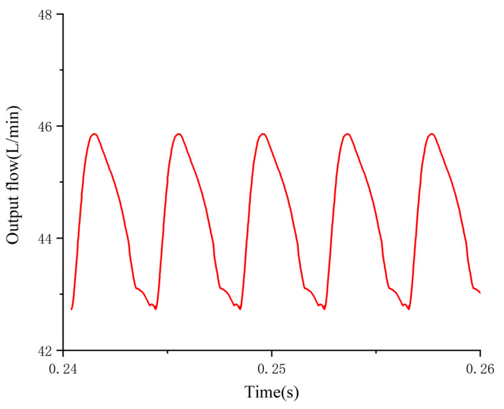
The prime mover is 1300 r/min, the swashplate angle is 12.5°, the misalignment angle is == 3°. The flow pulsation test curves of the nine-piston piston pump and ten-piston piston pump are shown in Figure 22 and Figure 23 and the comparison values of the experiment and simulation are shown in Table 4 [21]. Due to the influence of oil compressibility, friction, geometric pulsation, and elastic pulsation during the experiment, the flow pulsation value obtained from the experiment is slightly higher than the simulation value. When the number of pistons is 9, the flow pulsation rate of the model is 6.75% and the experimentally obtained flow pulsation rate is 7.11%, with an error rate of 5.1%; when the number of pistons is 10, the flow pulsation rate of the model is 6.21% and the experimentally obtained flow pulsation rate is 6.44%, with an error rate of 3.6%. The error rate between the model and the experimental data is low, the model is in better agreement with the experimental data, and the experiment verifies the correctness of the simulation model.
5. Conclusions
- (1)
- Through the above analysis, it can be seen that the speed of the prime mover, swashplate angle, diameter of the piston, and port plate structure of the piston pump have an important impact on the flow pulsation of the piston pump. In the actual work of the piston pump, in order to effectively reduce the flow pulsation of the plunger pump and reduce the noise caused by the flow pulsation, the port plate structure should be optimized. That is, the pre-compression angle and misalignment angle of the piston pump should be appropriately reduced, and the inclination of the swashplate and the rotation speed of the prime mover should be controlled within a certain range. When the swashplate angle is 5–10°, the output flow can quickly reach a stable state; when the speed of the prime mover is 1100–1300 r/min, the output flow of the plunger pump can quickly reach a stable state.
- (2)
- In order to reduce the flow pulsation and facilitate the processing and manufacturing in the project, for the odd-numbered piston pump, the pre-compression angle and misalignment angle should be = = 1°; for the even-numbered piston pump, the dead angle and staggered supporting role of the port plate should be = = 3°. At present, the nine-piston piston pump is commonly used in the project, but when the dead angle and staggered supporting role of the port plate are set at = =1°, the pulse rate of the nine-piston piston pump is very close to that of the ten-piston piston pump, which provides a theoretical basis for the popularization and application of the ten-piston piston pump.
- (3)
- The error rate between the model and the experimental data is low, and the model is in positive agreement with the experimental data. The correctness of the simulation model is verified through experiments, which provides a basis for the design and improvement of the piston pump.
Author Contributions
Conceptualization, R.L. and Q.L.; methodology, R.L.; software, Q.L.; validation, Y.C. (Yi Cheng), Q.S. and Y.Z.; formal analysis, J.L. and Y.C. (Yurong Chi); investigation, Q.L.; resources, R.L.; data curation, R.L.; writing—original draft preparation, R.L.; writing—review and editing, R.L.; visualization, Q.L.; supervision, Q.L.; project administration, R.L.; funding acquisition, R.L. All authors have read and agreed to the published version of the manuscript.
Funding
Funding was obtained from Key R&D plan of Shandong Province, China, grant number 2020CXGC010806; Key R&D plan of Shandong Province, China, grant number 2021CXGC010813; Key R&D plan of Shandong Province, China, grant number 2020CXGC011005; and innovation team project of colleges and universities of Jinan Science and Technology Bureau, Shandong Province, China, grant number 2020GXRC042.
Acknowledgments
I would like to thank my tutor, Ruichuan Li, for all of his support and guidance. I would like to thank my colleagues for their care and help in my daily work.
Conflicts of Interest
The authors declare no conflict of interest.
References
- Qian, W.X.; Gao, Q.H.; Li, X.Y.; Zhang, Y. Simulation Research on Flow Pulsation Characteristics of Axial Piston Pump Based on AMESim. Mach. Tool Hydraul. 2018, 46, 114–117. [Google Scholar]
- Qian, W.; Gao, Q.; Li, X.; Li, Y. Co-simulation Research on Flow Pulsation Characteristics of Plunger Pump Based on AMESim and ADAMS. In Proceedings of the 2017 5th International Conference on Mechatronics, Materials, Chemistry and Computer Engineering (ICMMCCE 2017), Chongqing, China, 15–16 December 2017. [Google Scholar]
- Xu, Z.Y.; Miao, X.H.; Zuo, H. The research on pulsation of pump pressure in water mist system. Energy Procedia 2015, 66, 73–76. [Google Scholar]
- Liu, Y.; Jiang, W.; Bao, C.W. Simulation Analysis of Flow and Pressure of Swashplate Axial Piston Pump Based on AMESim. Sci.-Tech. Innov. Product. 2019, 11, 50–53. [Google Scholar]
- Gao, L. Finite Element Analysis and Flow Pulsation of Key Components of Piston Pump. Master’s Thesis, Hebei University of Engineering, Handan, China, 2022. [Google Scholar]
- Zhang, H. Cavitation effect to the hydraulic piston pump flow pulsation. Appl. Mech. Mater. 2014, 599, 230–236. [Google Scholar] [CrossRef]
- Kojima, E.; Nagakura, H. Characteristics of Fluidborne Noise generated by Fluid Power Pumps: 1st Report, Mechanism of Generation of Pressure Pulsation in Axial Piston Pump. JSME Int. J. 2008, 25, 46–53. [Google Scholar] [CrossRef] [Green Version]
- Andreev, M.; Grätz, U.; Lamparter, A. Pipeline Simulation by the Method of Characteristics for Calculating the Pressure Pulsation of a High-Pressure Water Plunger Pump. publications.rwth-aachen.de, Aachen, Germany. 2018. Available online: http://publications.rwth-aachen.de/record/726223/files/726223.pdf?version=1 (accessed on 28 September 2022).
- Li, L. Effect of Indexing Valve Plate Angle on Swash Plate Moment and Instantaneous Flow Characteristics of Swash Plate Variable Axial Piston Pump. Master’s Thesis, Lanzhou University of Technology, Lanzhou, China, 2019. [Google Scholar]
- Han, J.L. Analysis of Flow Characteristics of Swashplate Axial Piston Pump. Master’s Thesis, Shandong University, Jinan, China, 2020. [Google Scholar]
- Han, X.; Sun, Z.G.; Yang, M. Flow Pulsation Analysis and Throttle Groove Optimization of Axial Piston Pump Based on FLUENT. Coal Mine Mach. 2021, 42, 24–27. [Google Scholar]
- Li, S.; Wang, G.Z. Research of Ripple in Piston Pump Based on Pre-compression Volume. Mach. Tool Hydraul. 2020, 48, 166–170. [Google Scholar]
- Zhu, H.; Bo, G.; Zhou, Y.B. Pump Selection and Performance Prediction for the Technical Innovation of an Axial-Flow Pump Station. Math. Probl. Eng. 2018, 2018, 1–9. [Google Scholar] [CrossRef]
- Zhang, T.X.; Zhang, N. Vibration Modes and the Dynamic Behaviour of a Hydraulic Plunger Pump. Shock. Vib. 2016, 2016, 1–7. [Google Scholar] [CrossRef] [Green Version]
- Olems, L. Investigations of the temperature behaviour of the piston cylinder assembly in axial piston pumps. Int. J. Fluid Power 2000, 1, 27–39. [Google Scholar] [CrossRef]
- Guo, F.; Gao, Y.Q.; Zheng, W. Influence of the Flux Pulsation on Pressure Pulsation of the Axial Piston Pump and Its Analysis. J. Shandong Univ. Sci. Technol. (Nat. Sci.) 2007, 5, 49–52. [Google Scholar]
- Xu, S.J. Study of Axial Piston Pump’s Pulsant Flux. Mach. Build. Autom. 2007, 3, 39–41+43. [Google Scholar]
- Wang, H.Y.; Wei, X.Y. Simulation Study on the Flow Pulsation Characteristics of Axial Piston Pump. Mach. Tool Hydraul. 2014, 42, 144–148. [Google Scholar]
- Yuan, H. Structural Optimization Design on the Key Parts of Swash Plate Axial Piston Pump. Master’s Thesis, Hefei Polytechnic University, Hefei, Chian, 2014. [Google Scholar]
- Hu, M. Design Investigation of The Swash Plate Axial Piston Pump with Conical Cylinder Blocks. Master’s Thesis, Lanzhou University of Technology, Lanzhou, China, 2011. [Google Scholar]
- Feng, K.; Borghesani, P.; Smith, W.A.; Randall, R.B.; Chin, Z.Y.; Ren, J.Z.; Peng, Z.X. Vibration-based updating of wear prediction for spur gears. Wear 2019, 426–427, 1410–1415. [Google Scholar] [CrossRef]
Figure 1.
Structural schematic diagram of swashplate axial piston pump. 1—Port plate; 2—back cover; 3—piston; 4—sliding boot; 5—swashplate; 6—drive shaft; 7—ball hinges; 8—return disc; 9—central spring.
Figure 1.
Structural schematic diagram of swashplate axial piston pump. 1—Port plate; 2—back cover; 3—piston; 4—sliding boot; 5—swashplate; 6—drive shaft; 7—ball hinges; 8—return disc; 9—central spring.
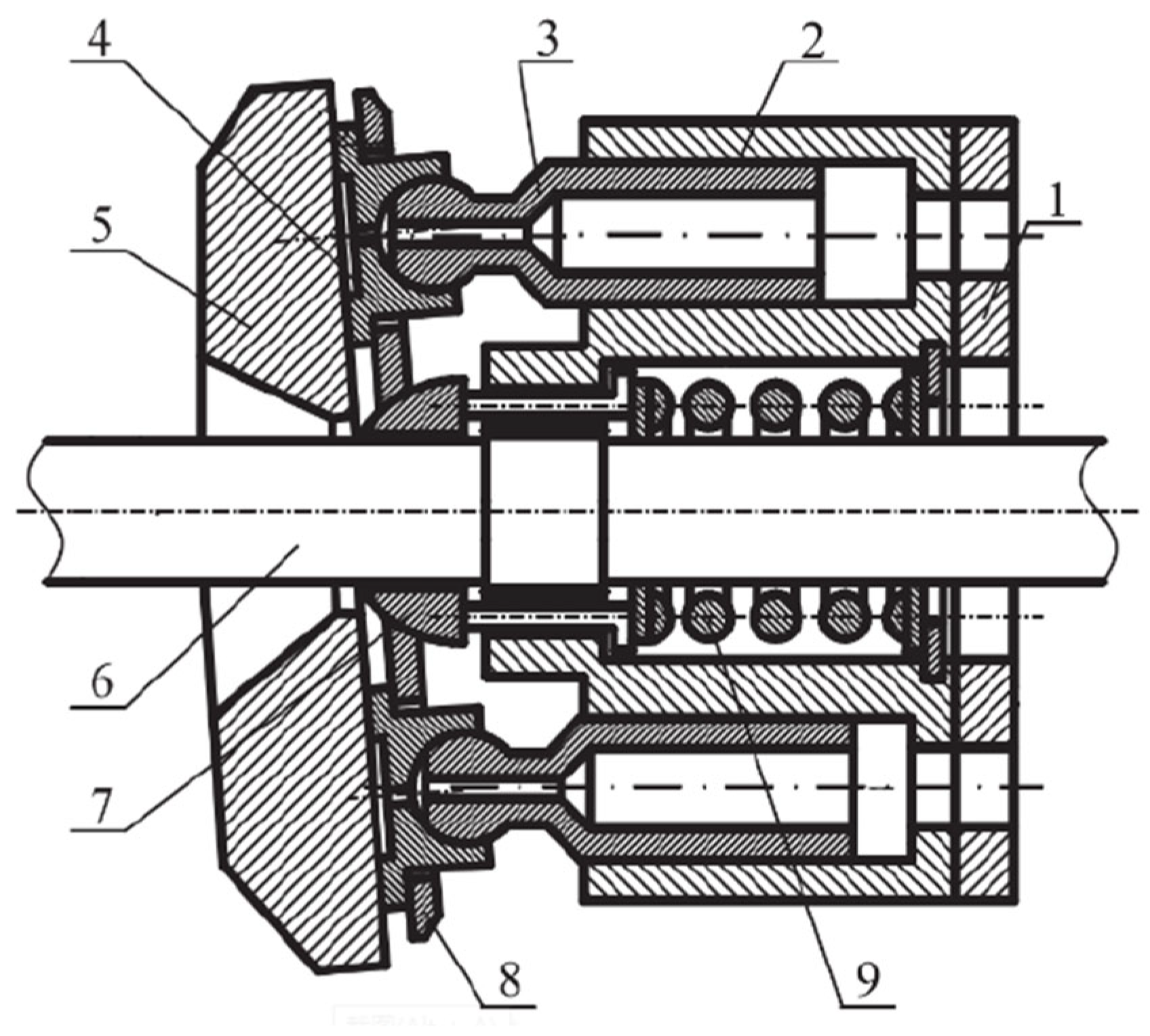
Figure 2.
Structural principle of swashplate axial piston pump.
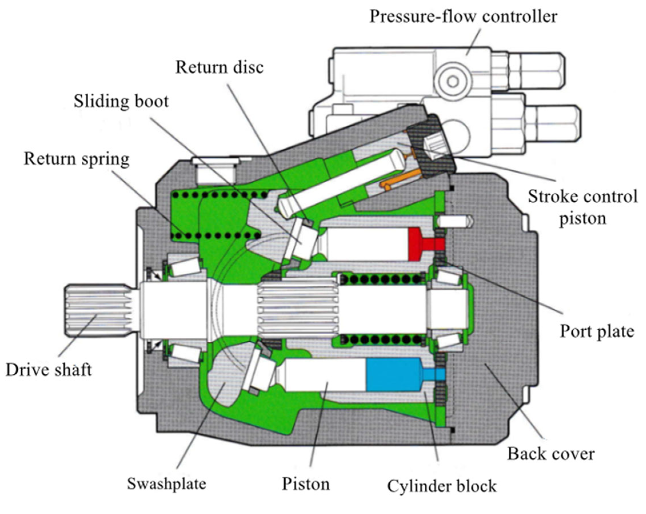
Figure 3.
Motion diagram of swashplate axial piston pump.
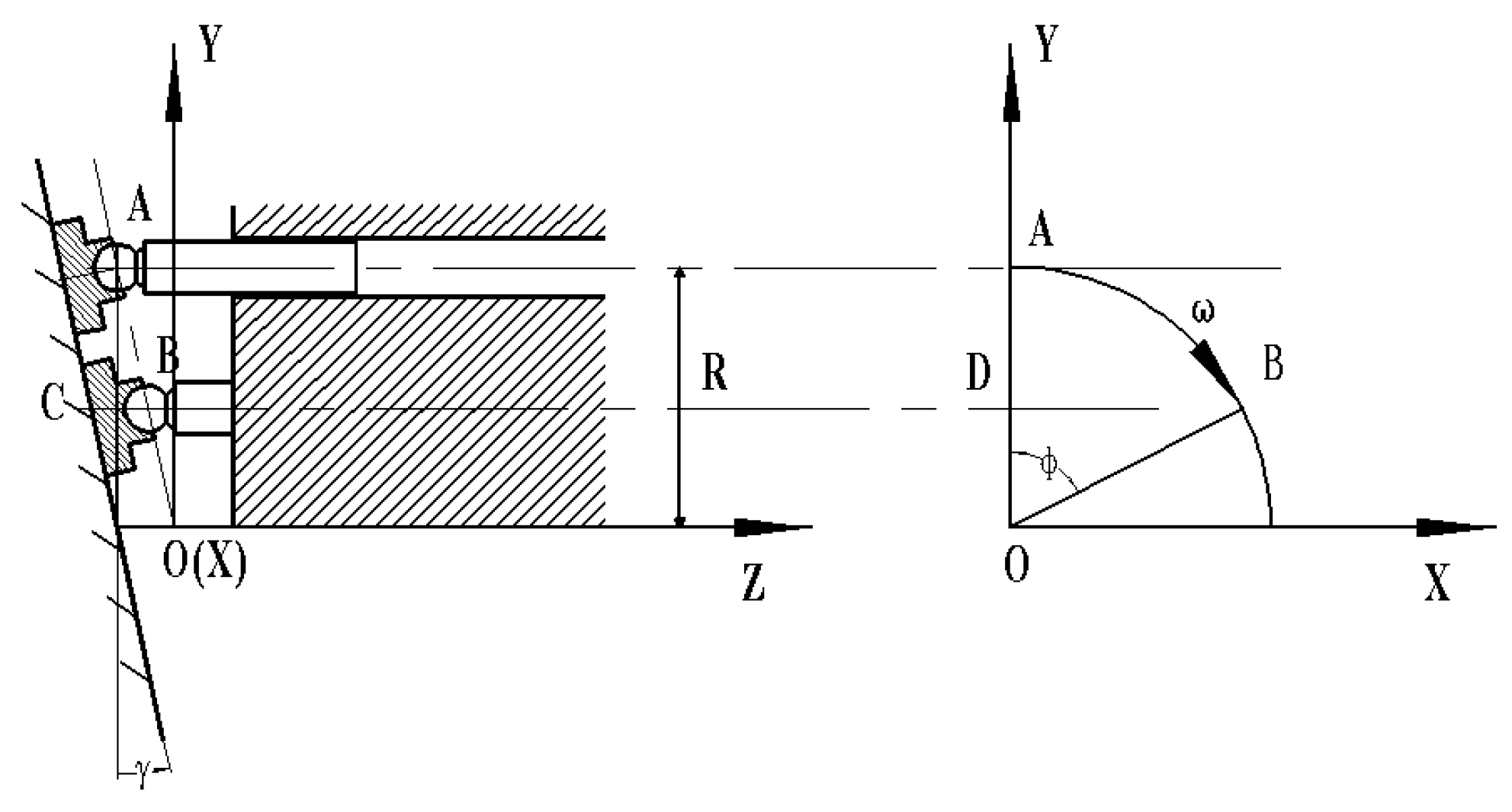
Figure 4.
Output flow pulsation curve of piston pump with 9 pistons.

Figure 5.
Output flow pulsation curve of piston pump with 10 pistons.
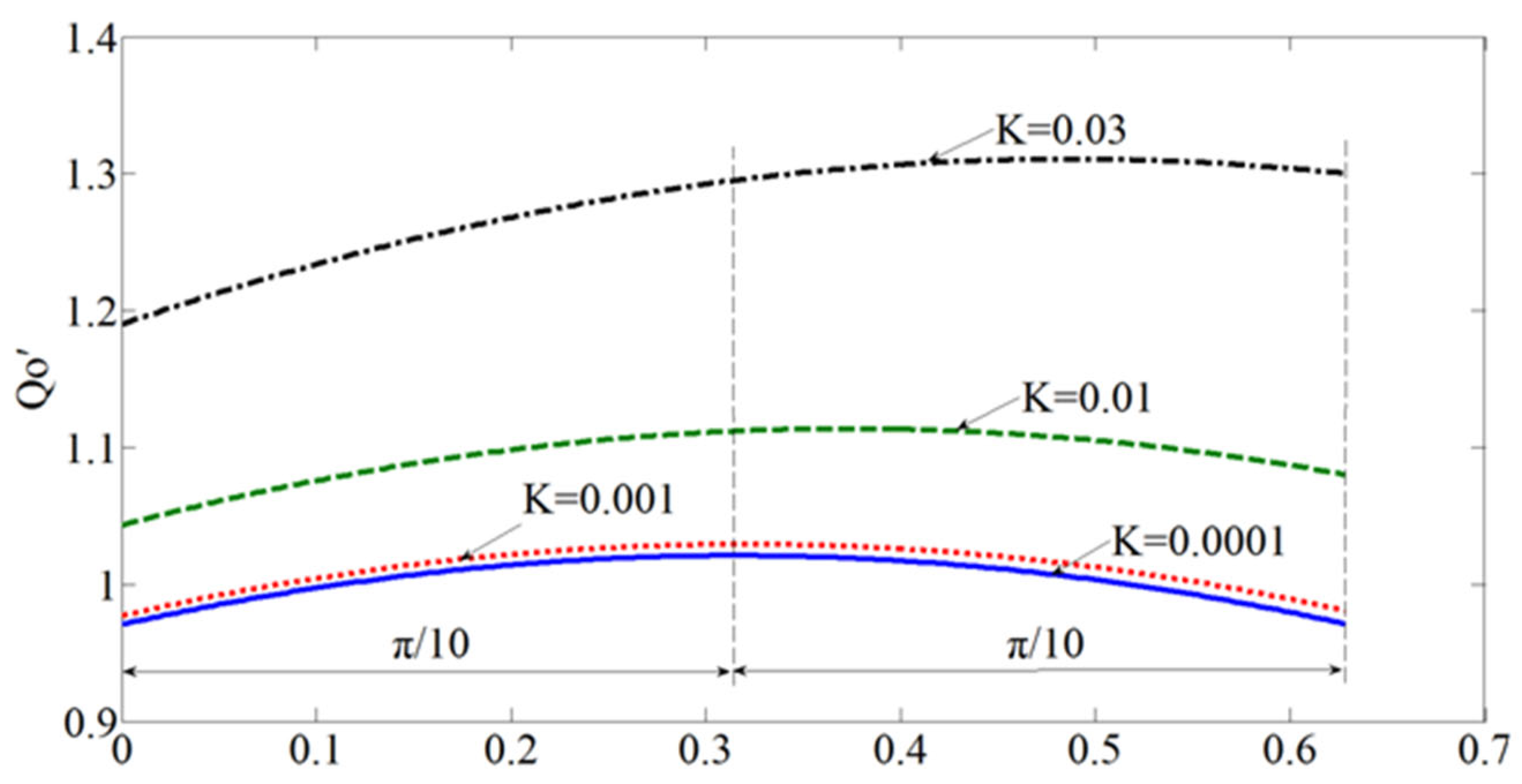
Figure 6.
Flow pulsation curve with different piston pump variable speed ratios.

Figure 7.
Single-piston model.

Figure 8.
Super-component of single piston.

Figure 9.
Simulation model of axial piston pump with 9 pistons.

Figure 10.
Pump output flow at different swashplate angles.
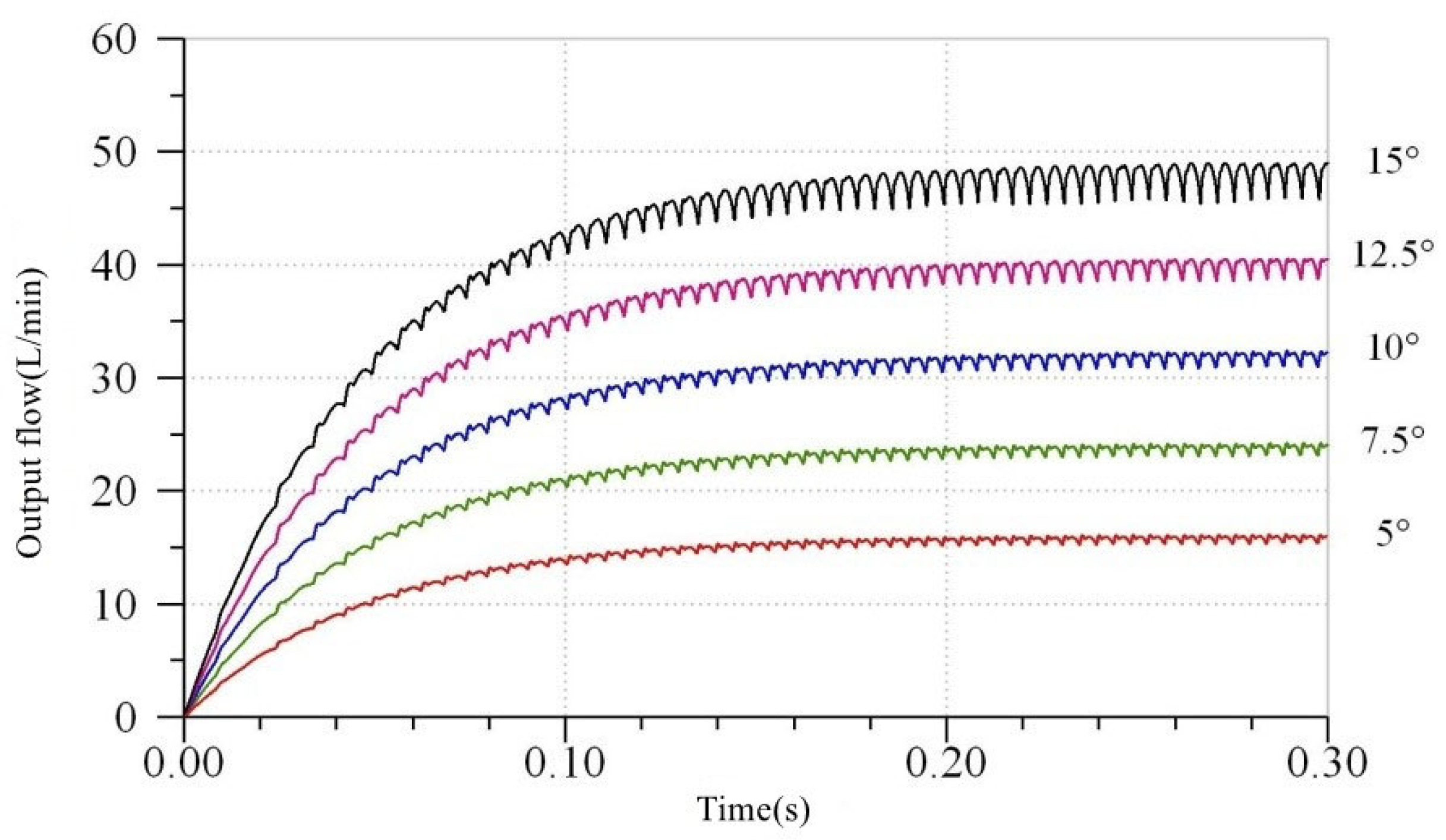
Figure 11.
Output flow when the speed of prime mover is 1100–1900 r/min.

Figure 12.
Pump output flow when piston diameter is 14–18 mm. (a) The output flow of the pump; (b) Enlarged view at A in Figure 12a.
Figure 12.
Pump output flow when piston diameter is 14–18 mm. (a) The output flow of the pump; (b) Enlarged view at A in Figure 12a.

Figure 13.
The typical symmetric port plate structure.

Figure 14.
The output flow of five port plate structures when z = 8. (a) Output flow at z = 8; (b) partial enlargement of Figure 14a.
Figure 14.
The output flow of five port plate structures when z = 8. (a) Output flow at z = 8; (b) partial enlargement of Figure 14a.

Figure 15.
When z = 9, the output flow of five port plate structures. (a) Output flow at z = 9; (b) partial enlargement of Figure 15a.
Figure 15.
When z = 9, the output flow of five port plate structures. (a) Output flow at z = 9; (b) partial enlargement of Figure 15a.
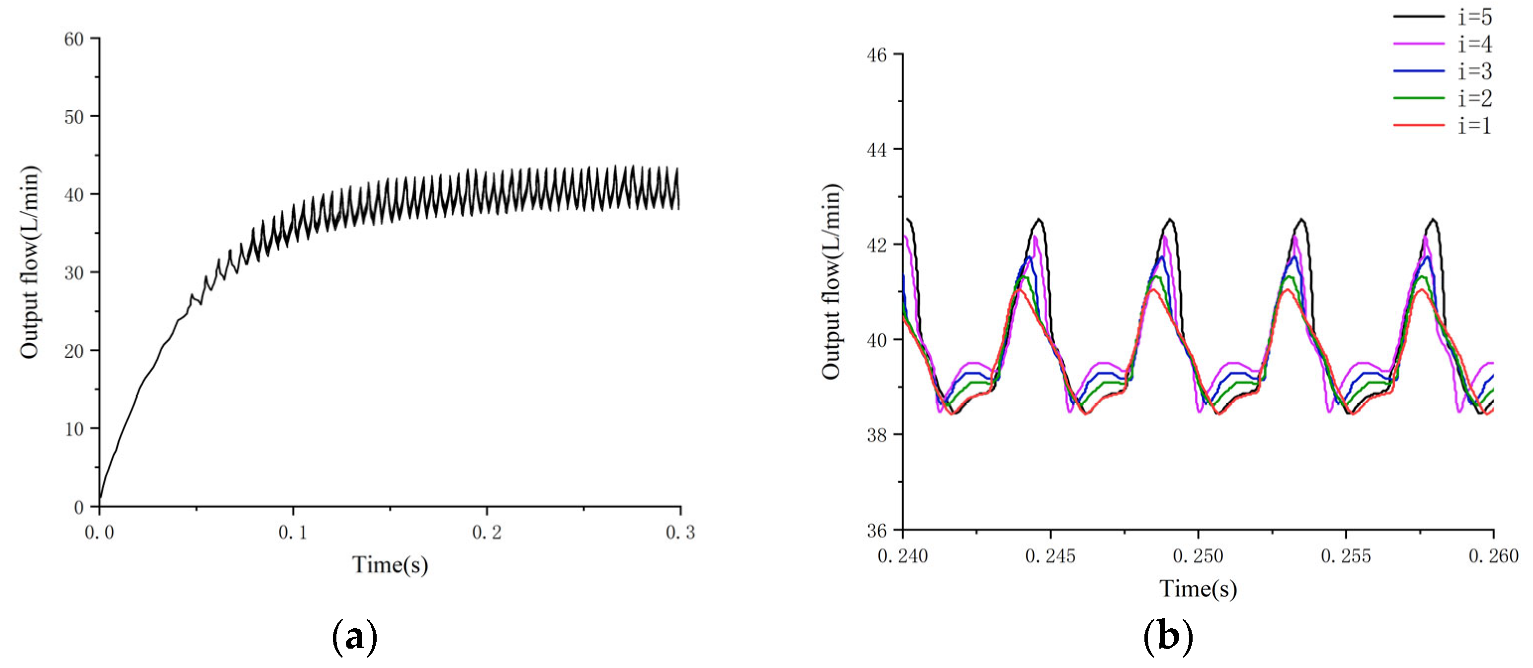
Figure 16.
The output flow of five port plate structures when z = 10. (a) Output flow at z = 10; (b) partial enlargement of Figure 16a.
Figure 16.
The output flow of five port plate structures when z = 10. (a) Output flow at z = 10; (b) partial enlargement of Figure 16a.
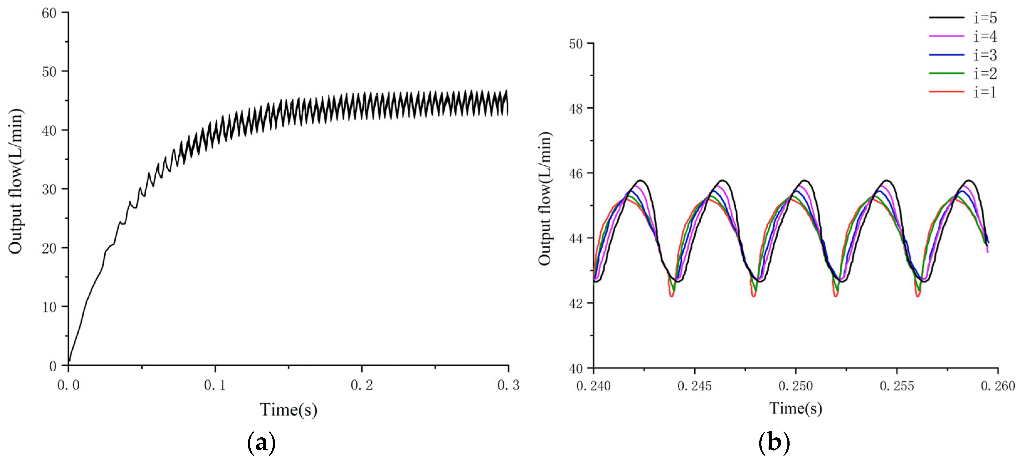
Figure 17.
The output flow of five port plate structures when z = 11. (a) Output flow at z = 11; (b) partial enlargement of Figure 17a.
Figure 17.
The output flow of five port plate structures when z = 11. (a) Output flow at z = 11; (b) partial enlargement of Figure 17a.
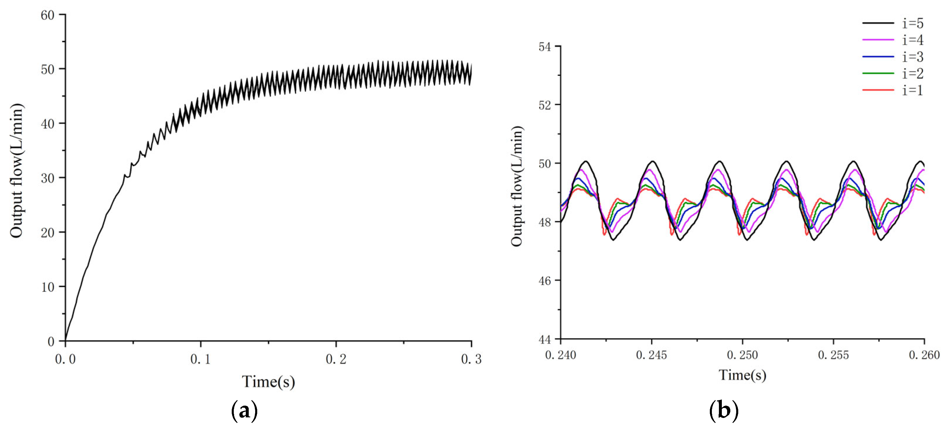
Figure 18.
Flow pulsation rate change diagram of pump under five port plate structures when the number of pistons is 8–11.
Figure 18.
Flow pulsation rate change diagram of pump under five port plate structures when the number of pistons is 8–11.
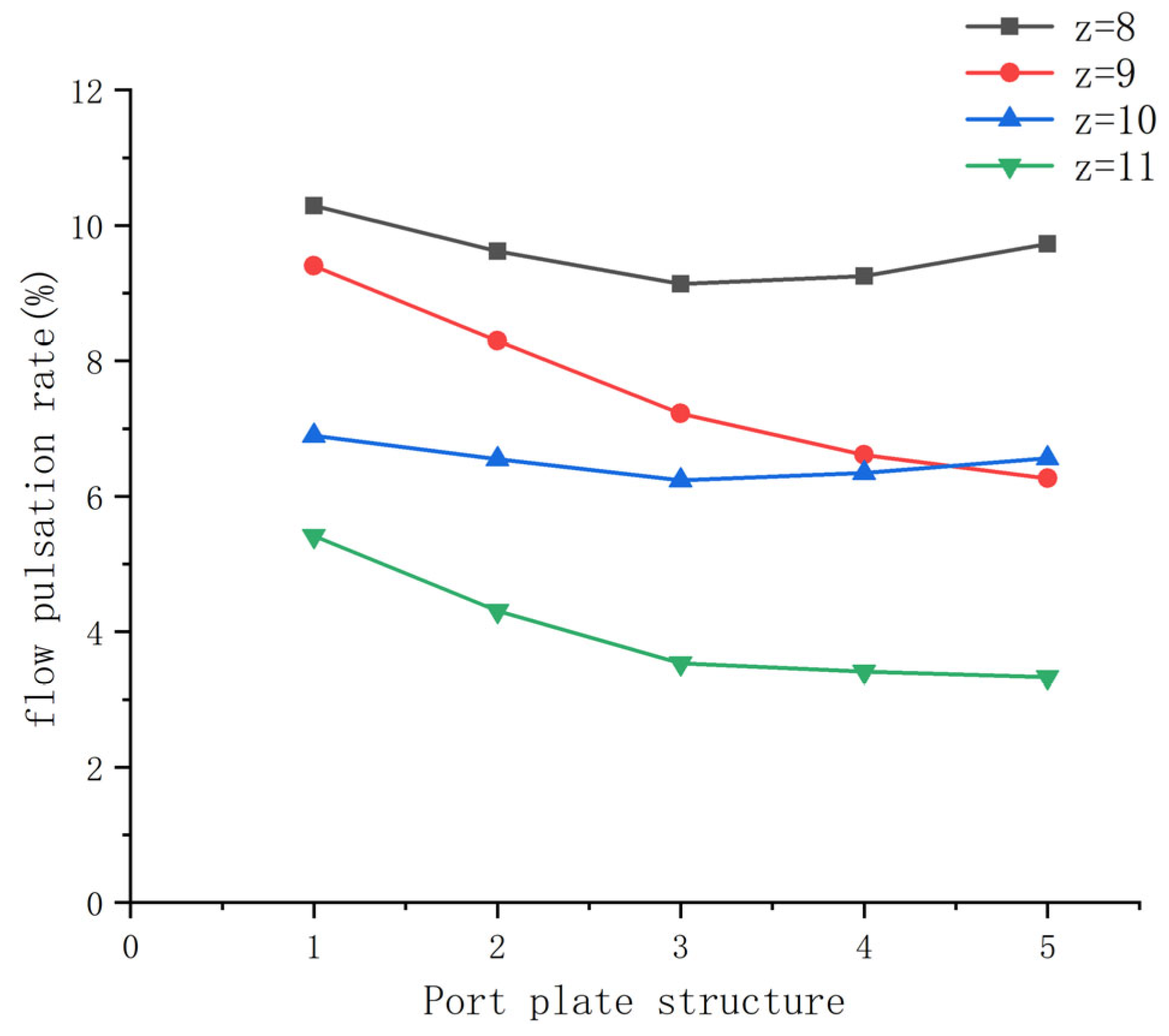
Figure 19.
Ten-piston axial pump. (a) Physical structure; (b) Disassemb drawing.
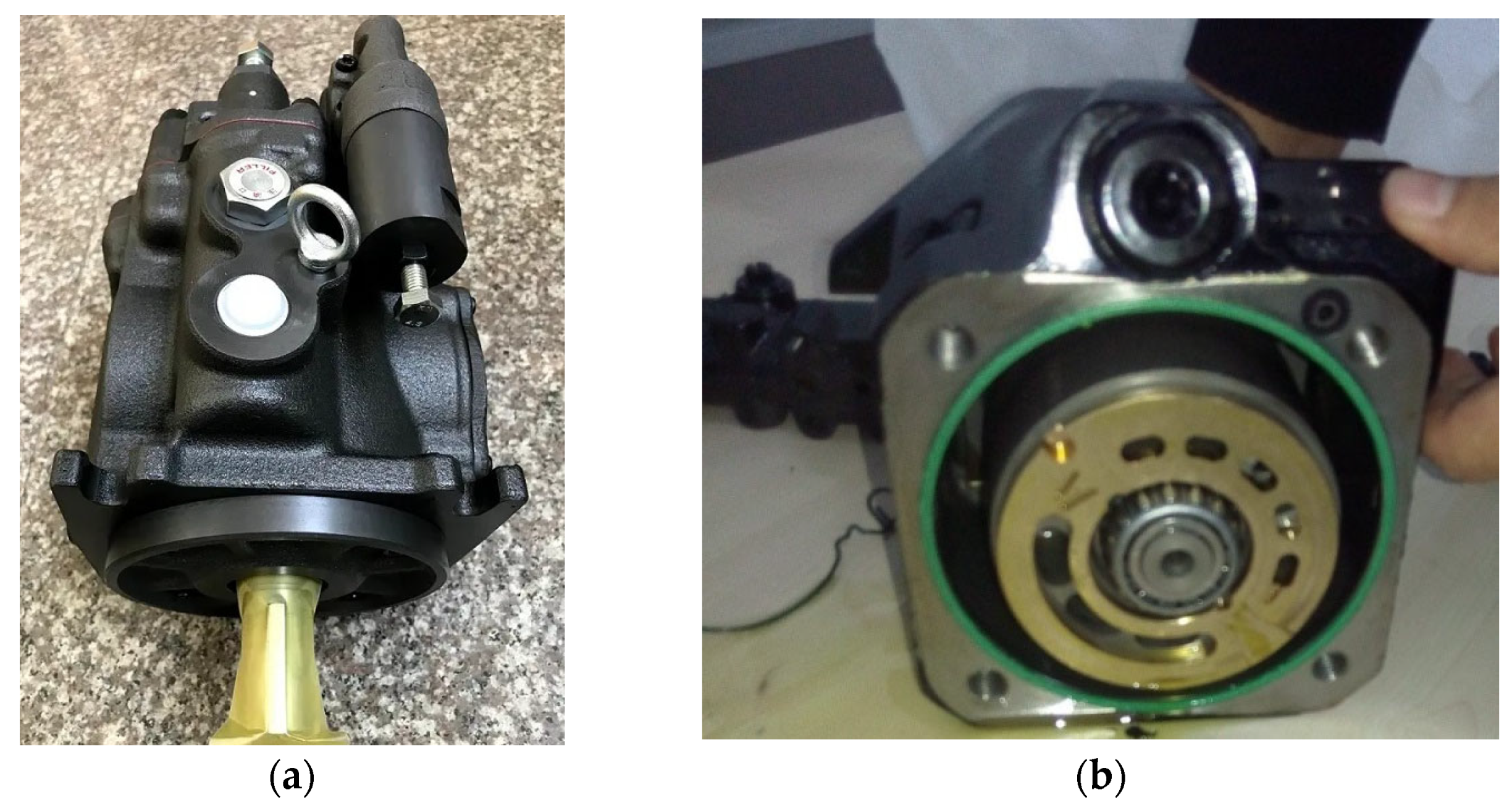
Figure 20.
The experimental schematic diagram. 1—Tank; 2—cut-off valve; 3—pressure gauge; 4—piston pump; 5—motor; 6—frequency converter; 7—overflow valve; 8—pressure gauge; 9—throttle valve; 10—flowmeter; 11—cut-off valve.
Figure 20.
The experimental schematic diagram. 1—Tank; 2—cut-off valve; 3—pressure gauge; 4—piston pump; 5—motor; 6—frequency converter; 7—overflow valve; 8—pressure gauge; 9—throttle valve; 10—flowmeter; 11—cut-off valve.
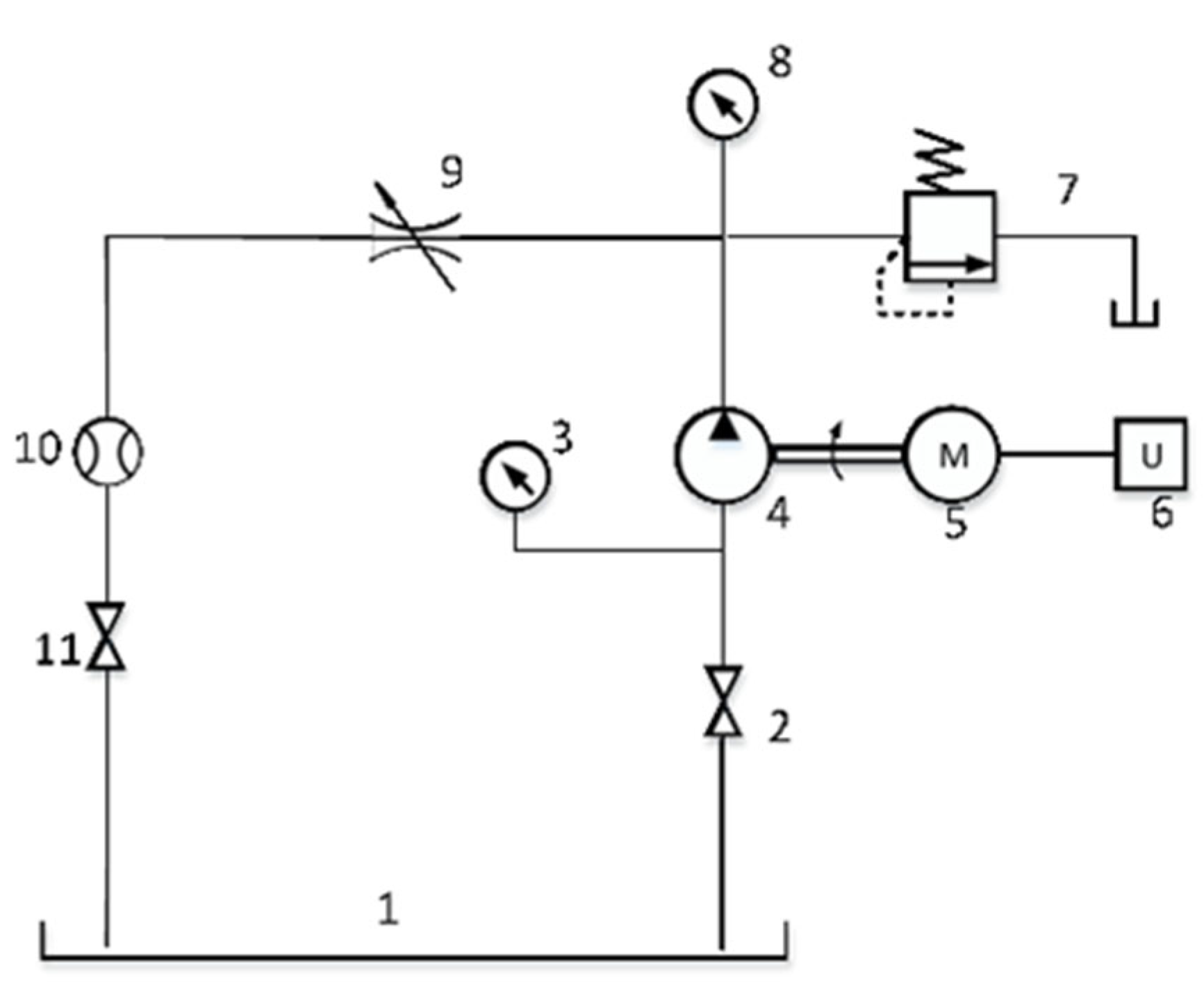
Figure 21.
Comprehensive performance test platform of piston pump.
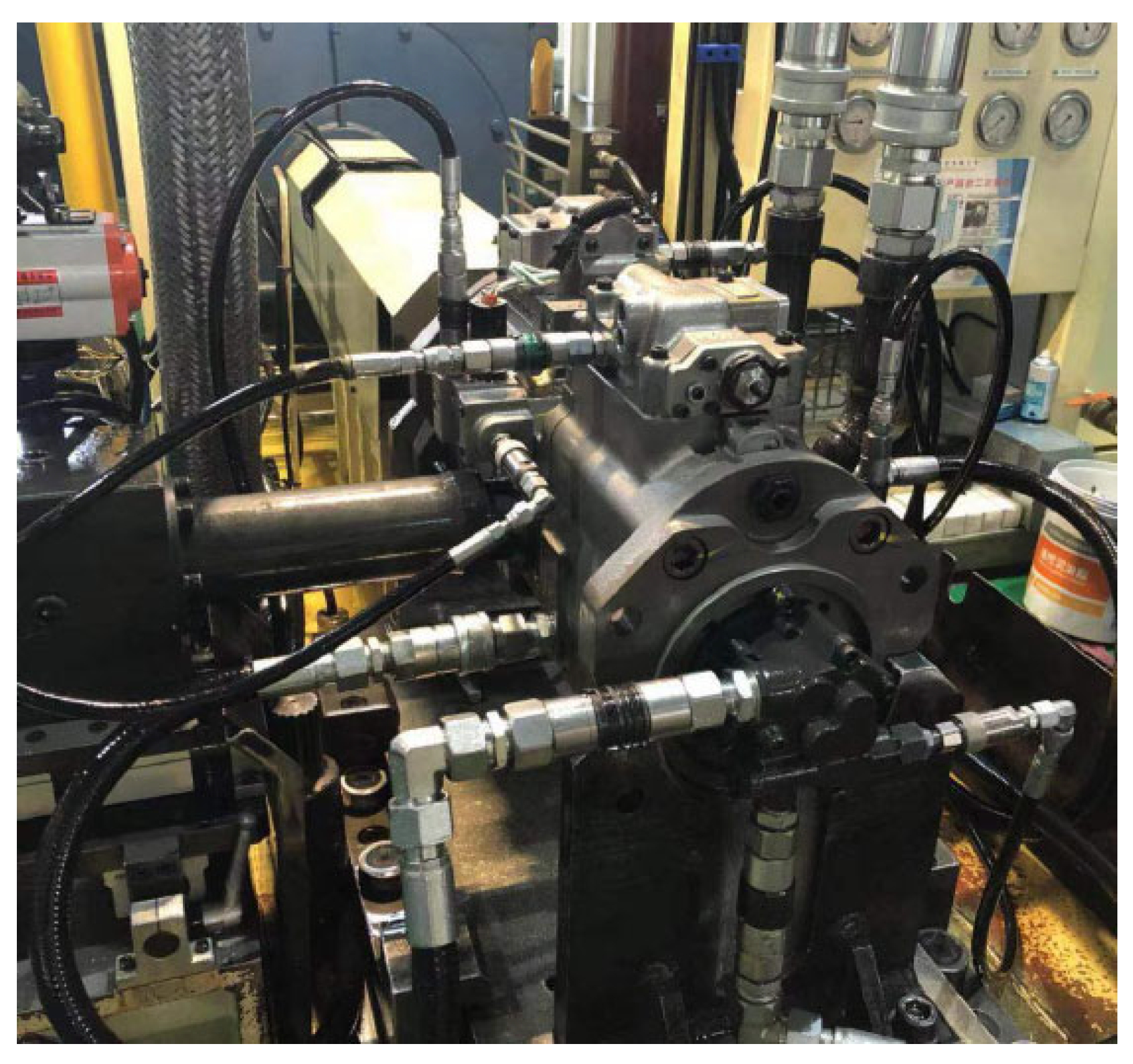
Figure 22.
Experimental diagram of a nine-piston piston pump.

Figure 23.
Experimental diagram of a ten-piston piston pump.

Table 1.
Output flow pulsation rate with different piston pump variable speed ratios.
| K (Variable Speed Ratios) | 0.0001 | 0.001 | 0.01 | 0.03 |
|---|---|---|---|---|
| , z = 9) | 1.47 | 1.83 | 4.78 | 11.97 |
| , z = 10) | 5.01 | 5.18 | 7.0 | 12.03 |
Table 2.
Five port plate structures.
| Type i Structure (i = 1–5) | Pre-Compression Angle (°) | Misalignment Angle (°) |
|---|---|---|
| 1 | 10 | 5 |
| 2 | 8 | 4 |
| 3 | 6 | 3 |
| 4 | 4 | 2 |
| 5 | 2 | 1 |
Table 3.
Flow pulsation rate of pump under five port plate structures when the number of pistons is 8–11.
Table 3.
Flow pulsation rate of pump under five port plate structures when the number of pistons is 8–11.
| Type I Structure (i = 1–5) | Pre-Compression Angle (°) | Misalignment Angle (°) | Flow Pulsation Rate (%) z = 8 | Flow Pulsation Rate (%) z = 9 | Flow Pulsation Rate (%) z = 10 | Flow Pulsation Rate (%) z = 11 |
|---|---|---|---|---|---|---|
| 1 | 10 | 5 | 10.25 | 9.50 | 6.91 | 5.39 |
| 2 | 8 | 4 | 9.55 | 8.31 | 6.56 | 4.31 |
| 3 | 6 | 3 | 9.07 | 7.30 | 6.19 | 3.51 |
| 4 | 4 | 2 | 9.20 | 6.61 | 6.30 | 3.34 |
| 5 | 2 | 1 | 9.70 | 6.36 | 6.60 | 3.28 |
Table 4.
Flow pulsation.
| Name | Simulation Value (%) | Experimental Value (%) | Error Rate (%) |
|---|---|---|---|
| Nine-piston piston pump | 6.75 | 7.11 | 5.1 |
| Ten-piston piston pump | 6.21 | 6.44 | 3.6 |
Publisher’s Note: MDPI stays neutral with regard to jurisdictional claims in published maps and institutional affiliations. |
© 2022 by the authors. Licensee MDPI, Basel, Switzerland. This article is an open access article distributed under the terms and conditions of the Creative Commons Attribution (CC BY) license (https://creativecommons.org/licenses/by/4.0/).
Share and Cite
MDPI and ACS Style
Li, R.; Liu, Q.; Cheng, Y.; Liu, J.; Sun, Q.; Zhang, Y.; Chi, Y. Analysis of the Influence of Structure and Parameters of Axial Piston Pump on Flow Pulsation. Processes 2022, 10, 2138. https://doi.org/10.3390/pr10102138
AMA Style
Li R, Liu Q, Cheng Y, Liu J, Sun Q, Zhang Y, Chi Y. Analysis of the Influence of Structure and Parameters of Axial Piston Pump on Flow Pulsation. Processes. 2022; 10(10):2138. https://doi.org/10.3390/pr10102138
Chicago/Turabian StyleLi, Ruichuan, Qi Liu, Yi Cheng, Jilu Liu, Qiyou Sun, Yisheng Zhang, and Yurong Chi. 2022. "Analysis of the Influence of Structure and Parameters of Axial Piston Pump on Flow Pulsation" Processes 10, no. 10: 2138. https://doi.org/10.3390/pr10102138
Note that from the first issue of 2016, this journal uses article numbers instead of page numbers. See further details here.