Article

Maximizing Lubricant Life for Internal Combustion Engines

by
Saúl Domínguez-García
1,
Luis Béjar-Gómez
1,
Andrés López-Velázquez
2,
Rafael Maya-Yescas
3 and
Fabricio Nápoles-Rivera
3,*
1
Faculty of Mechanical Engineering, Universidad Michoacana de San Nicolás de Hidalgo, Morelia 58000, Mexico
2
Faculty of Electrical Mechanical Engineering, Universidad Veracruzana, Xalapa 91000, Mexico
3
Faculty of Chemical Engineering, Universidad Michoacana de San Nicolás de Hidalgo, Morelia 58000, Mexico
*
Author to whom correspondence should be addressed.
Processes 2022, 10(10), 2070; https://doi.org/10.3390/pr10102070
Submission received: 14 September 2022 / Revised: 7 October 2022 / Accepted: 8 October 2022 / Published: 13 October 2022
(This article belongs to the Section Sustainable Processes)

Abstract

:
Although the lubrication systems for internal combustion engines have been designed to prevent engine wear and friction, their configuration does not contemplate the maximum use of each load of lubricant; because of this limitation, lubricant consumption is currently an environmental and economic problem. In this work, the performance of lubrication systems to form the tribological film that prevents wear is simulated and optimized, through the mass balance of the lubricant precursors contained in the oil and the implementation of optimal control techniques. Optimization results indicate that regulating the flow of lubricant passing through the engine prevents excessive degradation of lubricant precursors, maximizing the life of each lube oil charge, giving the possibility to increase the sustainability of internal combustion engines.

1. Introduction

Currently, work capacity and industrial production, as well as means of transport, are supported by the use of machinery and significant amounts of fuel. There are different ways to transform the chemical energy of fuels into mechanical energy and perform the necessary work to transport matter from one place to another; internal combustion engines are the most common ways to make this transformation, and of these, diesel and gasoline engines are the most used in automobiles and machinery. For example, trains, ships, and all road freight vehicles that use these types of engines.
Combustion engines are equipped with cooling and lubrication systems. These help to improve efficiency by reducing fuel consumption per unit of power produced and to extend service life. Additionally, preventive maintenance programs are required to ensure that these machines do not suffer excessive wear and work in adequate conditions. One of the essential maintenance practices for internal combustion engines is changing the oil or lubricant to ensure that the engine does not wear excessively and to reduce power losses due to friction.
One of the disadvantages of the lubrication system used in internal combustion engines is the waste of exhausted oil removed from the lubrication system, this waste should be properly treated to avoid contamination of water and subsoil, although, there are some ways to recycle or to give other use to lubricants, much of this waste is carelessly discarded [1,2]. Other disadvantage of these lubrication systems is the monetary cost, since many transportation and transformation companies expend too much money replenishing the lubricant of their engines. Having these problems, it is necessary to carry out research that lead to a reduction of the lubricant consumption resulting from the use of the internal combustion engines [1,2].
It should be noted that the lubrication process that occurs within the lubrication systems is quite complex and even today there is not a complete understanding of the phenomena, from the mechanical and physicochemical point of view, that occurs during the operation of these lubrication systems. In addition, due to the differences in the nature of the phenomena that occur in the lubrication process, a multidisciplinary research approach is required. Therefore, in an attempt to obtain this knowledge, there is research to develop more efficient and sustainable lubricant formulations; there is research that models and simulates the phenomenon of lubrication from a plastic-mechanical perspective; and there is additional research that also models and simulates the phenomenon of lubrication but from a tribochemical perspective. Some examples of these works are:
Studies aiming to achieve more efficient and sustainable formulations: The research of J. A. Carlos Cornelio et al., 2016 studied the tribological properties of functionalized nanotubes (single and multi-walled) modified with carboxylic acid and their results indicated that carbon nanotubes provoke a decrease in both the friction coefficient and the wear rate for oil and water lubricated systems [3]. The work of P. Zulhanafi and S. Syahrullail, 2018, studied the effect of tertiary Hydroquinone as an anti-oxidant agent and their results revealed that tertiary Hydroquinone reduces the coefficient of friction and provides a smooth surface roughness [4]. J. Panda et al., 2021, assessed the performance of solid lubricants, polytetrafluoroethylene, polyether ether ketone, and poly aryl ether ketone, to mention a few examples, to impart very low friction and enhance wear resistance, their results showed that the transfer of a polymeric film on a countersurface achieves ultralow wear and friction in a dry condition [5]. K. Chowdary et al., 2021, reviewed the tribological and thermophysical mechanisms of bio-lubricants for automotive applications [6].
Other works focus on the modeling and simulation of the lubrication phenomenon from a plastic-mechanical perspective. The research of Zhao et al., 2016, developed a lubrication model that considers the deformation of the protective tribolayer and the angle of the connecting rods in the wear of the piston cylinder surfaces in internal combustion engines [7]. Fang, Meng, and Xie, 2017, proposed a lubrication model for internal combustion engines in order to investigate the influence of grooves on the dynamics of friction between pistons and cylinders [8]. Akchurin et al., 2015, and Akchurin, Bosman, and Lugt, 2017, proposed a lubrication model to simulate the generation of wear particles in boundary contact lubrication regimes between sliding surfaces [9,10]. Azam, Dorgham, et al., 2019, developed a model that unifies the previous lubrication approaches [11]. However, none of the previous works considered the evolution of the protective layer precursors that form the tribolayer, followed by the chemical degradation of the lubricating compounds and the wear of the tribolayer. One of the first publications that considers the chemical degradation of the lubricant is the research of Ghanbarzadeh et al., 2016, which developed a tribochemical model based on the thermodynamics and kinetics of tribolayer formation [12]. Another example of tribochemical lubrication models is the research of Azam, Dorgham, et al., 2019, which developed a model that considers both aspects: the phenomena considered by the mechanical-plastic models and the tribochemical phenomena [13]. There is also a research carried out by Dominguez-Garcia et al., 2022, which modeled, simulated, and predicted lubricant life for a conventional lubrication system that operated in unregulated conditions of lubricant supply to the internal engine [14]. Note that the above lubrication model carried out by Dominguez-Garcia et al., 2022, is used as the starting point for the current research.
However, until now, the increasing of life of each lubricant batch used in internal combustion engines has not been addressed from an optimization perspective that provides a more efficient way to supply the lubricant inside of the engine. Therefore, in this work, the performance of lubrication systems to form the tribological film that prevents wear is simulated and optimized, through the mass balance of the lubricant precursors contained in the oil and the implementation of optimal control techniques.

2. Problem Definition

2.1. Lubrication in Internal Combustion Engines

Lubrication systems for internal combustion engines consist of an oil pan that contains the lubricating oil, a pump that sends the oil through the engine, and a filter that prevents the arrival of abrasive particles to the interior of the engine (Figure 1). Once the lubricating oil reaches the interior of the engine, three situations can occur, depending on the kind of relative movement of the internal parts of the engine, the speed and pressure of the lubricant flow: the less extreme condition of lubrication is the hydrodynamic regime that occurs in axes and bearings where lubricant can flow separating the surfaces on movement, of course, this separation requires of the adequate speed and pressure of the lubricant; on the contrary, the most extreme condition of lubrication is the boundary regimen that occurs in valves train and piston cylinder assembles, since these subsystem of the engines require the seal of the parts, in this situation there is not flowing lubricant between surfaces, so to avoid wear of this parts, a solid film must be deposited and remains over surfaces; and the other condition of the lubrication is the mixed regimen that is characterized by the switching between the hydrodynamic regimen and the boundary regimen, it occurs during starting, load bumping and engine shutdown.
In the case of the boundary regimen, which is the targeted condition in this work, the lubricant precursors are deposited on the internal surfaces of the engine and react chemically to form a protective layer, called tribofilm, which prevents direct contact between sliding surfaces [15,16,17,18,19,20,21]. During its operating time, this tribofilm is mechanically removed from the surface, changing its thickness and nanostructural properties. Under these conditions, the thickness of the tribofilm that remains on the internal surface of the engines is the result of the competition between the speed of its formation and the speed of its removal [22,23].
The speed of formation of the tribofilm depends on some kinetic parameters, such as the temperature and the catalytic effect of the surface where it is deposited, as well as the transport of the lubricant precursors in the oil that is inside the engine and its concentration [23]. The removal rate of the tribofilm depends mainly on mechanical properties and variables, such as its nanostructure, its thickness, the charge on the surface and the speed of movement. Note that it also depends on the tribofilm thickness itself, since if the tribofilm thickness is less than the roughness of the surfaces in contact, the removal rate will be reduced by the contact between the roughness peaks, and the thickness of the tribofilm cannot be larger than the maximum separation of the sliding surfaces [22,23], since the tribofilm excess formed beyond this maximum separation is instantly removed, unnecessarily depleting the reserve of lubricant precursors.
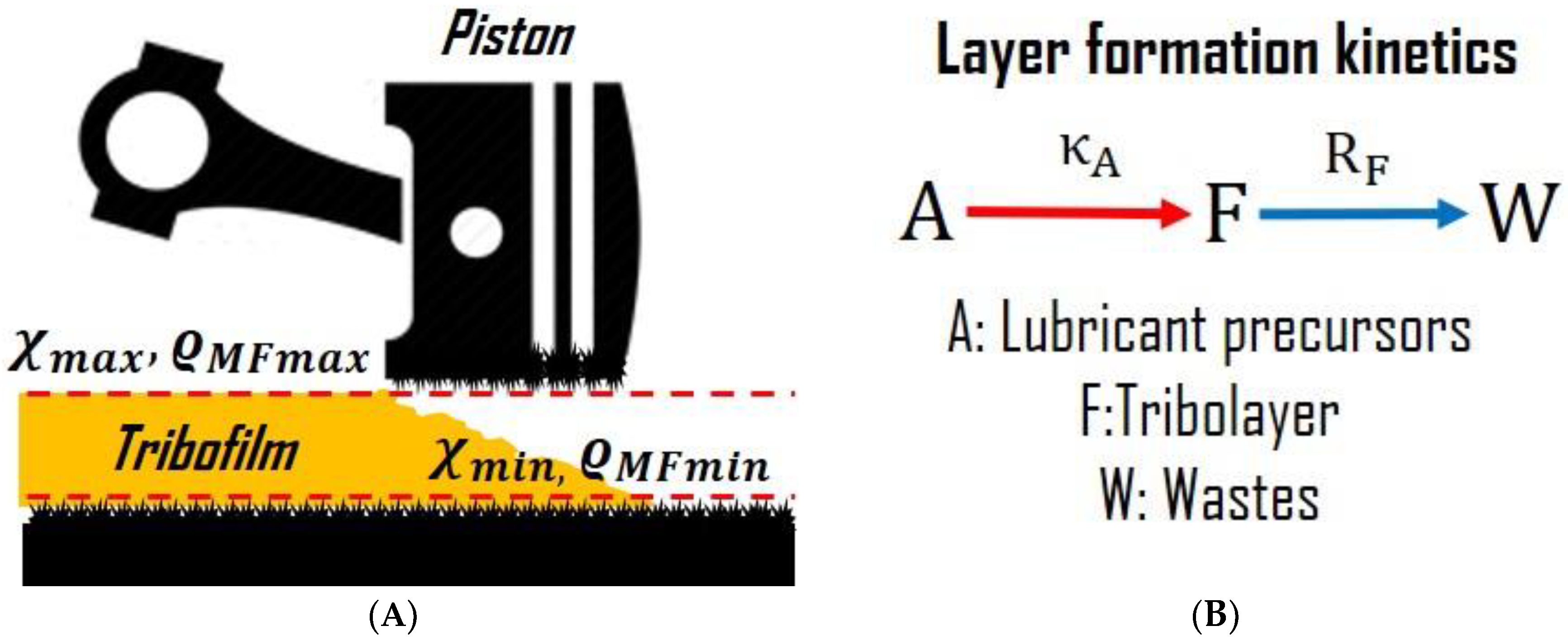
In order to model the simultaneous processes of formation and removal of the lubricating tribofilm (Figure 2A) in a simplified way, a previous work has suggested that the dynamics of the thickness of the tribofilm (Figure 2B) is represented by two monomolecular, first-order, and sequential reactions [14]. The first reaction takes place when the agglomerate of lubricant precursors (A), consisting of the lubricant additives and the oil molecules that carry them, chemically reacts to form the tribofilm agglomerate (F) on the surfaces. The second reaction represents the removal of the tribofilm due to the sliding of the moving parts of the engine, converting the tribofilm into the agglomerate of waste substances (W), which no longer has the ability to renew the tribofilm.

2.2. Mathematical Model for the Lubricating System

This model represents the lubrication system by two rigid vessels containing the lubricant, the oil pan with volume ( V C ), and the engine with volume ( V M ). The oil pan is connected to the engine by a pump that supplies a volumetric flow of lubricant ( u ) from the oil pan to the engine; the supplied lubricant flow contains certain weight-volume ratio of lubricant precursors ϱ C A . In the engine, the lubricant precursors A are transformed into tribofilm (F) (Figure 2B), and after one residence time, the volumetric flow of lubricant u is recirculated to the oil pan vessel but containing a smaller amount of the weight-volume ratio of lubricant precursors ϱ M A (Figure 1).
The classical mass balances for the lubricant precursors of this model are described as:
The accumulation of lubricating precursors A in the oil pan vessel V C d ϱ C A d t , is counted as the mass coming from the inside of the engine that reaches the oil pan vessel minus the mass coming from the oil pan vessel that is supplied to the inside of the engine ϱ M A ϱ C A u (1).
d ϱ C A d t = 1 V C ϱ M A ϱ C A u
The accumulation of lubricant precursors A inside the engine V M d ϱ M A d t is counted as the mass entering and leaving the oil pan vessel ϱ C A ϱ M A   u minus the rate of consumption of lubricant precursors due to the formation of tribofilm κ A   ϱ M A (2). It is worth mentioning that this rate of consumption is due to the first-order monomolecular reaction, which contains the tribofilm formation constant κ A (Figure 2B).
d ϱ M A d t = 1 V M ϱ C A ϱ M A u κ A ϱ M A V M
The accumulation of tribofilm F inside the engine V M d ϱ M F d t is counted as the rate of tribofilm formation σ κ A   ϱ M A minus the rate of tribofilm removal ς R F (3). It should be noted that κ A and R F are experimental parameters that depend on temperature, catalytic effect, engine speed, and other mechanical variables [14] and that must be determined experimentally [23,24,25,26,27,28,29,30]. For this work, the operation of the engine was considered in steady state, therefore these two parameters are assumed to be constant.
d ϱ M F d t = σ κ A ϱ M A V M ς R F V M
In order to restrain tribofilm growth to its physical limits, two additional parameters are introduced σ , ς . The first parameter σ restricts tribofilm growth above ϱ M F m a x , which is the amount of tribofilm mass needed to reach the maximum separation χ m a x between two sliding surfaces inside the engine (Figure 2A), so if χ > χ m a x then σ = 0 (4), avoiding the growth of the tribofilm. On the contrary, if the thickness of the tribofilm is less than or equal to its maximum value χ χ m a x , then σ = 1 , allowing tribofilm growth (4).
σ = 0 , χ > χ m a x 1 , χ χ m a x
The second parameter ς restricts tribofilm removal below ϱ M F m i n , that is, the tribofilm mass needed to achieve the minimum separation to avoid direct contact between rubbing surfaces χ m i n inside the engine (Figure 2A); thus, if χ χ m i n , then ς = 1 (5), allowing free elimination of the tribofilm. On the other hand, if χ < χ m i n , then ς = χ χ m i n , slowing down the elimination of the tribofilm, since below this thickness the roughness peaks appear (5). In addition, the last ratio approximates the roughness distribution, which is a normal probability curve called Archard’s equation [23,31,32,33,34].
ς = 1 , 1 χ m i n , χ χ m i n χ < χ m i n
The relationship between the thickness of the tribofilm χ and the amount of mass in the tribofilm ϱ M F is determined by the tribofilm mass on the internal surface area of the engine ( A R ) where the slip occurs (6).
χ = χ m i n + V M ρ F A R ϱ M F ϱ M F m i n , ϱ M F ϱ M F m i n χ m i n ϱ M F ϱ M F m i n 1 / 2 , ϱ M F < ϱ M F m i n
The last equation comes from solving the weight-volume ratio definition for tribofilm ϱ M F (7), the density of the tribotribofilm ρ F (8), and the volume variation of the tribofilm v M F with respect to its thickness d v M F d χ (9); m M F is the mass of the tribolayer deposited over the internal surface area of the engine.
ϱ M F = m M F V M
ρ F = m M F v M F
d v M F d χ = A R ς
The solution of Equations (7)–(9), taking the definite integral of (9), from zero to χ m i n and from χ m i n to χ m a x , gives the relationship between χ m i n and ϱ M F m i n (10) and the relationship between χ m i n and ϱ M F m a x (11), respectively.
ϱ M F m i n = ρ F A R χ m i n 2 V M
ϱ M F m a x = ϱ M F m i n + ρ F A R χ m a x χ m i n V M
Note that, in this model of the lubrication system, since the inside of the engine and the oil pan vessel are connected by two pipelines (Figure 1), the flow u is controlled by the lubricant pump. Under these conditions, a proposal to avoid excessive depletion of the tribofilm formed is to regulate the flow of lubricant passing through the engine, consequently controlling the amount of lubricant precursor available inside the engine for the tribofilm formation of and, consequently, the speed of tribofilm formation. This objective is revisited in Section 4.2.

2.3. Experimental Estimation of the Model Parameters

Although, this research is technically a mathematical study of lubrication system behavior, it is convenient, for the understanding of this work, to briefly address the procedure to experimentally estimate the tribofilm formation constant κ A and the tribofilm removal rate R F , as well as the roughness measurement of surfaces, which in this work is proposed as the minimum thickness of the film χ m i n .
A way to estimate the value of the tribofilm formation constant κ A for a specific operation temperature of internal combustion engines is by means of runs to form films at different deposition times [23], later, the thickness of the films is measured by means of the scanning electron microscopy; then, assuming that the superficial area of each sample where the film was deposited is the same and the surface of all samples is completely flat, the volume of the deposited film is estimated and so the mass of the deposited film is estimated from a known film density. Once, the mass of the deposited films is known, a monomolecular first-order kinetic is adjusted to estimate the tribofilm formation constant κ A by means of linear regression. This procedure was used in previous research, which obtained a suitable adjustment of film growth along time [23], besides, in this same research, the value of the tribofilm removal rate is estimated by computing the ratio of the removed film mass over time [23].
For the estimation of the roughness height, a roughness meter is used. This device measures the roughness height by scaring the samples’ surfaces, giving the arithmetic mean of the roughness height over the sampling length, the maximum height of the peak and the maximum depth of the valley relative to mean roughness, the maximum roughness height and others roughness parameters. For this research, it was assumed that the roughness height is 500 nm, since this value approximated the maximum roughness height reported in previous research [23].

3. Materials and Methods

3.1. Maximization Methodology

The objective of this research is to maximize lubricant life in internal combustion engines, which can be achieved through the implementation of the optimal control methodology, searching the best route for a system that evolves over time and is susceptible to external stimuli. However, before dealing with the best route of lubrication, is proper to get an intuition of this method.
In the approach of a mathematical problem of optimal control, the starting point is having a set of first order ordinary differential equations d x d t = f x , u , t (12), which define and, at the same time, constrain the system along time, as well as a set of algebraic equations g x , u , t (13) and a set of inequalities h x , u , t (14), which also constrain the system. In order to control the route followed by the system, through a trajectory that connects an initial state and a final state, the system variables are classified into state variables x, which define the response of the system, and control variables u , which are the external stimuli that provoke the response of the system.
f x , u , t = d x d t
g x , u , t = 0
h x , u , t 0
To quantify the performance of the system, the performance index J ( τ ) is defined (15), which integrates all points of the route followed the system along its trajectory between the initial state and the final state. This function includes other function, L x , u , t that define the behavior of the system, which is desired to optimize, such a function should be carefully chosen, accordingly with the objective to optimize the route of the state x t , to optimize the use of the control u t , or to simultaneously optimize both. Another thing to consider when choosing L x , u , t is that this function meets the sufficient conditions, the criteria of the second derivatives, so that the optimal route found is the absolute optimal route of the system. These conditions are always fulfilled in the case of functions that are convex, so, very often, quadratic performance indices are chosen in optimal control problems. It is worth mentioning that both J τ and L x , u , t may not have a physical meaning, however, their optimal values guarantee an optimal route for convex functions [35].
J τ = 0 τ L x , u , t d t
The optimal control methodology states that the optimal route of a function conditioned by certain constraints is at the stationary points of a new unconstrained function constructed as linear combination of the performance function L x , u , t and the functions involved in the constraints f x , u , t and g x , u , t . This function (16), known as the Hamiltonian or motion function, consists of coefficients regarded as Lagrange multipliers, adjoining variables, or co-state variables, λ and γ (16). In the case of static optimization problems, the adjoining variables λ and γ are constant; however, in the case of optimal control, which are dynamic problems, the adjoining variables λ t and γ t also evolve over time.
H = L x , u , t + λ f x , u , t + γ g x , u , t
Note that in Equation (16) the inequality restrictions h x , u , t do not appear, because these restrictions are less rigorous than the equality restrictions f x , u , t and g x , u , t ; in a first attempt to find the optimal route, they are left out of the equation of motion and then it is verified that the optimal route found is within the feasible region, delimited by the inequality restrictions h x , u , t . If these constraints are not satisfied, when they are left out of the Hamiltonian, then, to correct this situation, such constraints can be added as equality constraints, forcing the system to move on the inequalities boundaries [35,36,37].
Once the equation of motion has been established, the necessary conditions to find the optimal route are determined by the first partial derivatives of the Hamiltonian H with respect to the state variables x , the control variables u , and the adjoining variables λ and γ . Following the optimal control methodology, the derivative H / x should be set equal to d λ / d t (17), the derivative H / u should be set equal to 0 (18), the derivative H / λ should be set equal to d x / d t (19) and the derivative H / γ must be set equal to 0 (20). The deduction of these equations is out of the scope of this article, so the reader is recommended to review the bibliography specialized in optimal control, in the bibliography section there are some references on this topic [37,38].
H x = d λ d t
H u = 0
H λ = d x d t = f x , u , t
H γ = g x , u , t = 0
The solution of optimal control problems is complicated, since the adjoining variables, or co-state variables, are given by ordinary differential equations, which require an unknown initial or final condition that, in general, it is not a physical value that cannot be intuited; instead, there are initial and final conditions for the state variables.
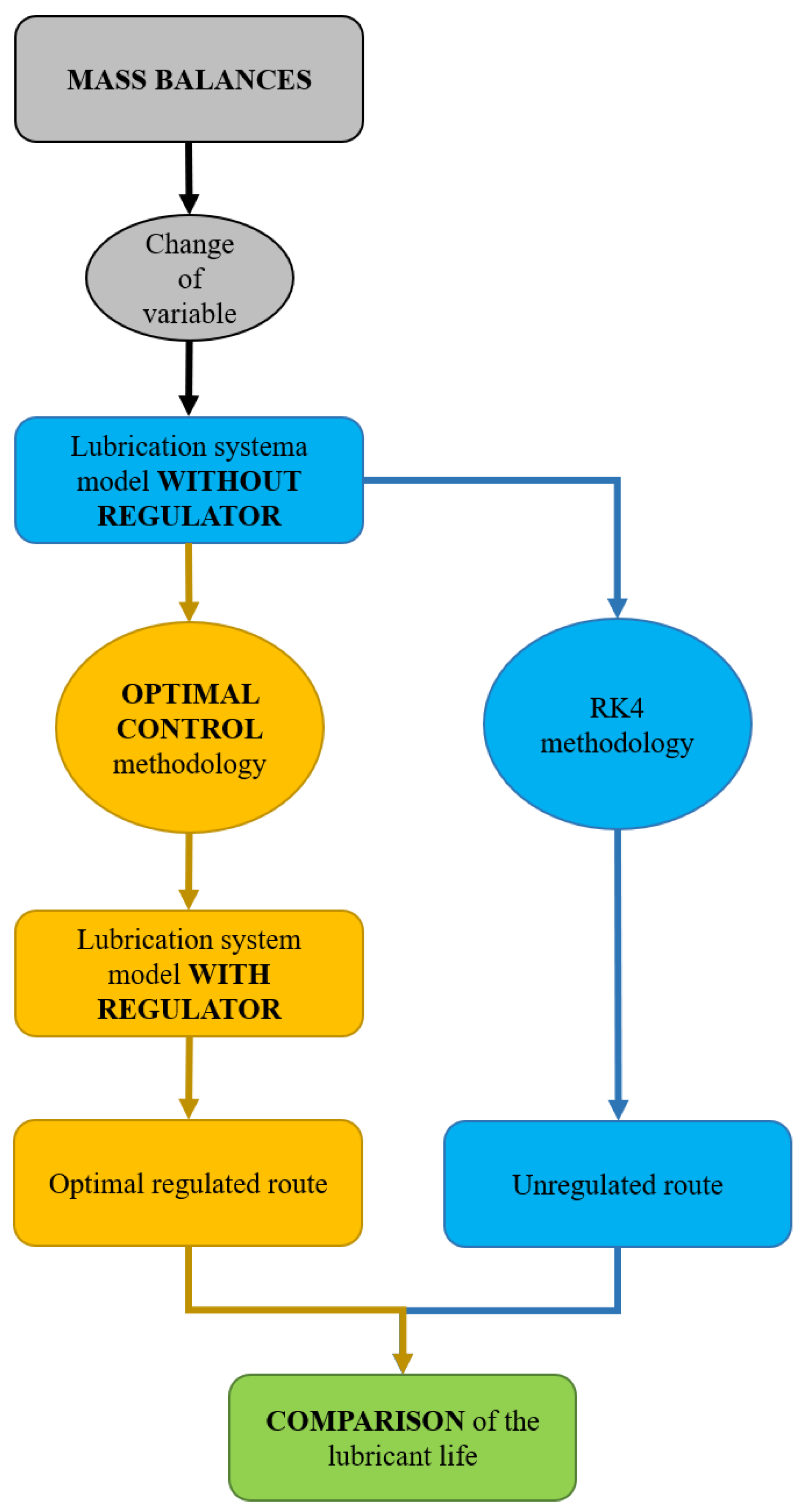
In this work, it is assumed that the amount of lubricant precursor and the thickness of the tribofilm evolve over time, during the entire period of use of each load of lubricant and the optimal route sought is the one that maximizes the duration of each load of lubricant. The differential equations that determine the evolution of the amount of lubricant precursor and the film thickness are the mass balances given in Equations (1)–(3), while Equations (4)–(6) are the algebraic restrictions of the system, given by sections. However, to reduce the complexity of the optimal control methodology applied to this system, first, it is necessary to make a change of variable and some adjustments, which allows finding the optimal route for regulating the flow of lubricant sent through the engine. Figure 3 shows the flow diagram of the procedure to compare the lubricant life of each load of lubricant used in the lubrication systems with and without regulation of the lubricant supply to the engine.

3.2. Lubrication System Model without Regulator

Now, the variable θ A is introduced, which is the difference between weight-volume ratio of lubricant precursor A in the oil pan and the weight-volume ratio of lubricant precursor A in the engine inside (21) and its derivative respect to time (22).
θ A = ϱ C A ϱ M A
d θ A d t = d ϱ C A d t d ϱ M A d t
Combining Equations (21) and (22) with Equations (1) and (2), it is possible to obtain Equations (23) and (24).
d ϱ M A d t = 1 V M θ A u κ A ϱ M A V M
d θ A d t = 1 V C + 1 V M θ A u κ A ϱ M A V M
These two equations, together with Equation (3) and restrictions (4)–(6), complete the mass balance of the lubricant precursors and the tribofilm formed inside the engine.
Then, with the mathematical model given by these equations, it can be defined that the state variables for a lubrication system WITHOUT A REGULATOR, where the lubricant supply flow between the oil pan and the inside of the engine u is constant, are ϱ M A , θ A , and ϱ M F .

3.3. Lubrication System Model with Regulator

Nevertheless, to implement the control of the lubrication system that maximizes its useful life, the lubricant flow u must be regulated continuously during the life time of each lubricant charge τ, in addition, the requirements of lubrication that prevent engine wear have to be satisfied, that is, impose new restrictions on the lubrication system to ensure that the tribofilm mass ϱ M F remains stable during τ and that χ is held at the maximum χ m a x level of film thickness inside the engine. The previous restrictions imply that Equations (25) and (26) are satisfied. Note that the maximum thickness was chosen as a restriction and not the minimum thickness, to give the system reliability, preventing a minimum disturbance driving the lubrication system to operate in the rough region of the surface (Figure 2A).
d ϱ M F d t = d ϱ M A d t = 0
σ = ς = 1
Combining (25) and (26) with (3), (23), and (24), Equations (27)–(29) are obtained, which complete the mass balances for a lubrication system with regulation of the supply of lubricant between the oil pan and the engine inside u .
ϱ M A e = R F κ A
0 = θ A u κ A ϱ M A e
d θ A d t = κ A ϱ M A e V C
Here, ϱ M A e is the weight-volume ratio of the lubricant precursor A, inside the engine, necessary to tribofilm removal rate balances the tribofilm growth rate. It should be noted that ϱ M A e is a constant parameter for each lubrication system, since it only depends on two parameters, the tribofilm formation constant κ A and the tribofilm removal rate R F .
At this time, already with the mathematical model given by Equations (28) and (29), it can be defined the state variable for the lubrication system WITH A REGULATOR, where the lubricant supply flow between the oil pan and the engine inside u is regulated, is θ A and the control variable is u .
To find the route that minimizes the lubricant flow u that passes through the engine, in this work, the functional 1 2 u 2 is proposed. This functional, being a quadratic function, ensures the existence of one absolute minimum. Note that the factor 1/2 is only a weight factor that facilitates the handle of the control equation. The performance index for this functional is computed as the area under the curve during the operation time τ (30).
J = 0 τ 1 2 u 2 d t
Later, incorporating the performance functional of Equation (30) and the constraints that define the regulated lubrication system in the equation of motion, the Hamiltonian, using the co-state variables γ and λ for the algebraic constraint (28) and for the differential restriction (29) respectively, it is obtained (31).
H = 1 2 u 2 + γ θ A u κ A ϱ A e λ κ A ϱ A e V C
Then, setting the partial derivative of H with respect to the state variable θ A equal to the negative of the ordinary derivative of λ with respect to time, equating the partial derivative of H with respect to the control variable u to 0, equating the partial derivative of H with respect to the co-state variable γ with 0 and equating the partial derivative of H with respect to the co-state variable λ with the ordinary derivative of θ A with respect to time, as established in the optimal control methodology, the necessary conditions for a critical route are defined, for the lubrication system, by Equations (32)–(35).
H θ A = d λ d t = γ u
H u = 0 = u γ θ A
H γ = 0 = θ A u κ A ϱ A e
H λ = d θ A d t = κ A ϱ A e V C
To find the critical route of the lubrication system that minimizes the flow of lubricant passing through the engine, the set of Equations (32)–(35) must be solved, which, due to the introduction of the variable θ A in the mass balances, can be solved sequentially, starting with Equation (35), since it is a constant ordinary differential equation, whose integration results in a straight-line function, which gives the route of the state of the system, in terms of the difference of weight-volume ratio of lubricant precursors between the oil pan and the engine θ A , during the time of use of each load of lubricant (36), then, from Equation (34) the optimal regulated route of the lubricant flow u that passes through the engine during the time of use of each lubricant load is solved, which results in a hyperbolic function (37) and which, as will be seen in the results section, establishes the maximum feasible duration of each load of lubricant.
θ A = θ A 0 κ A ϱ A e V C t
u = κ A ϱ A e θ A
Note that, since u is an inverse function of θ A (37), when this state variable approaches 0, then u tends to infinity, defining the feasible limit of operation of the lubrication system with a regulator, in other words, the maximum time τ * that the regulator can satisfy the lubrication restrictions (25) and (26). This limit can be computed by setting Equation (36) equal to 0, substituting τ * for t, and then solving for τ * (38).
τ * = V C θ A 0 κ A ϱ A e
After obtaining the state and control routes of the lubrication system, the route for the adjoining variable γ (39) is obtained by substituting (36) and (37) in Equation (33). The route for the adjoining variable λ (40) is obtained with a little more effort, from Equation (32), since it requires a change of variable, some of algebra and integral calculus, to yield the following result:
γ = κ A ϱ A e θ A 2
λ = λ 0 + 1 2 V C κ A ϱ A e 1 θ A 2 1 θ A 0 2
Note that to find the critical state and control routes of the lubrication system, it is not required to know the functions for the routes of the adjoining variables (39) and (40); however, their existence guarantees that the state route (36) and control route (37) satisfy the necessary conditions for the critical points of the equation of motion, the Hamiltonian (31). In addition, note that in the function for the adjoining variable λ the unknown initial condition λ 0 appears, this would be a big complication if the state and control critical routes depended on λ , since there is no easy way to estimate the correct value of λ 0 ; however, in this optimal control problem, the state and control routes do not depend on the adjoining variables, so those adjoining variables can be allowed to take any value.

3.4. Arrangements to Compare the Lubrication System Performance

To complete the necessary mathematical arrangements in the COMPARISON of the performance of the lubrication system, the performance indices are used for both conditions, with and without a control, which are obtained by integrating Equation (30), resulting in Equation (41) for the route of the lubrication system without a control and Equation (42) for the optimal route of the lubrication system with a regulator.
J = 1 2 u ¯ 2 τ
J = 1 2 V C κ A ϱ A e 1 θ A 0 κ A ϱ A e V C τ ¯ 1 θ A 0
In the performance index for the system without a control (38), u ¯ is the average flow of lubricant circulating through the engine during the useful life of each lubricant charge τ in the performance index for the system with a regulator (39) and τ ¯ is the time in which the optimal control route reaches the value of u ¯ . It should be noted that u ¯ in both performance indices is the same flow; however, while the lubrication system without a control always works with a supply rate u ¯ , the lubrication system that follows the optimal route regulates the value of u until u ¯ is reached, in time τ ¯ . This last time interval is obtained by substituting u ¯ and τ ¯ for u and τ in Equations (36) and (37) and then solving for τ ¯ (43).
τ ¯ = V C θ A 0 κ A ϱ A e V C u ¯

4. Results and Discussion

4.1. Analysis of the Behavior of the Lubrication System without Control

First, to observe the behavior of the lubrication system without a control, a lubrication system loaded with 4 L of fresh lubricant in the oil pan was simulated of which, 2 L are inside the engine when it is working V M and the other 2 L remains in the oil pan when the engine is operating V C , it was assumed that the lubricant inside the engine and in the oil pan was a fresh lubricant, which initially contained 40 g/L of lubricant precursors, so the initial difference of lubricant precursors between the oil pan and engine θ A 0 was 0 g/L, the initial weight-volume of tribofilm inside the engine ϱ M F 0 was 0 g/L, the average rate of lubricant supply inside the engine u ¯ was 60 L/h, the assumed kinetics constant of tribofilm formation κ A was 6.4 × 10⁻⁵ L/s, the assumed rate of film removal R F was 3.20 × 10⁻⁴ g/s, the maximum deposited tribofilm thickness χ m a x was 1000 nm, and the roughness thickness χ m i n was 500 nm. The simulation was carried out by simultaneously solving Equations (3)–(6), (23) and (24), by implementing the RK4 method.
From the simulation of the lubrication system in the previous conditions, the state route followed by the lubrication system without a regulator for 2 L of lubricant in the oil pan was obtained. Figure 4A shows the thickness profile of the tribofilm χ , which, at the beginning, at time 0 h, has a value of 0 nm and then grows, almost immediately, until reaching the maximum value of the roughness χ m a x , there it is maintained until hour 36; after that time, the thickness decreases rapidly until it is below the minimum thickness of the roughness χ m i n , where the peaks of the roughness appear, from that moment the thickness continues to decrease, approaching to 0 nm, but with a rate slowed down due to the contact between the rugosities of the sliding surfaces.
Figure 4B shows the profile of the difference in weight-volume ratio between the oil pan and the engine θ A , which at the beginning, at time 0 h, has a value of 0 g/L of lubricant precursors, since, at that instant, the lubricant that is in both, the oil pan and the engine inside, has the same concentration of lubricant precursors, then it grows, almost immediately, until it reaches a maximum value of 0.07 g/L and, from that moment, it begins to decrease, slowly approaching to 0 g/L. It should be noted that the instant when the film thickness begins to decrease indicates the useful life of each lubricant charge τ for this unregulated lubrication system.

4.2. Analysis of the Behavior of the Lubrication System with Regulator

Subsequently, to observe the behavior of the lubrication system with a regulator, a lubrication system loaded with 4 L of fresh lubricant in the oil pan was simulated, of which, 2 L are inside the engine when it is working V M and the other 2 L remains in the oil pan when the engine is operating V C , it was assumed that the lubricant in the oil pan was fresh lubricant, initially containing 40 g/L of lubricant precursors, and that the lubricant inside the engine was aged lubricant ϱ A e , initially containing 5 g/L of lubricant precursors, so the initial difference of lubricant precursors between the oil pan and the inside of the engine θ A 0 was 35 g/L, the assumed kinetics constant of tribofilm formation κ A was 6.4 × 10⁻⁵ L/s, the assumed rate of film removal R F was 3.20 × 10⁻⁴ g/s, the maximum deposited tribofilm thickness χ m a x was 1000 nm, and the roughness thickness χ m i n was 500 nm. The simulation was carried out by simultaneously solving Equations (36) and (37).
From the simulation of the lubrication system in the previous conditions, the state route followed by the lubrication system with a regulator for 2 L of lubricant in the oil pan was obtained. Figure 5A shows the profile of the difference of the weight-volume ratio between the oil pan and the inside of the engine θ A , which at the beginning, at time 0 h, has a value of 35 g/L of lubricant precursors, since at that moment, the lubricant in the oil pan contains 40 g/L of lubricant precursors and the lubricant inside the engine has only 5 g/L of lubricant precursors, which is the amount necessary to balance the rates of film formation and removal; then, it decreases with constant slope, until reaching a minimum value of 0 g/L at 61 h.
Figure 5B shows the profile of the lubricant flow u that must be supplied to the interior of the engine so that the rates of film formation and removal are balanced and the film thickness remains stable, at the maximum thickness of the tribofilm χ m a x , during the entire period of operation of the lubrication system, which, at the beginning, at time 0 h, has a value of 0.03 L/h and from that moment it grows hyperbolically to infinity at hour 61. It should be noted that, the instant in which the difference in weight-volume ratio of the lubricant precursors θ A decreases to 0 g/L, indicates the maximum useful life of each lubricant charge τ * for this lubrication system with a regulator, however, this value is only a mathematical limit, since an infinite flow of lubricant is impossible, instead, to compare both lubrication systems, it was considered as maximum flow of lubricant that equal to the average supply of lubricant inside the engine u ¯ equal to 60 L/h, which, using Equation (43), gives a useful life of each lubricant charge τ ¯ that is approximately equal to 61 h.

4.3. Comparison of the Behavior of the Lubrication System with and without Regulator

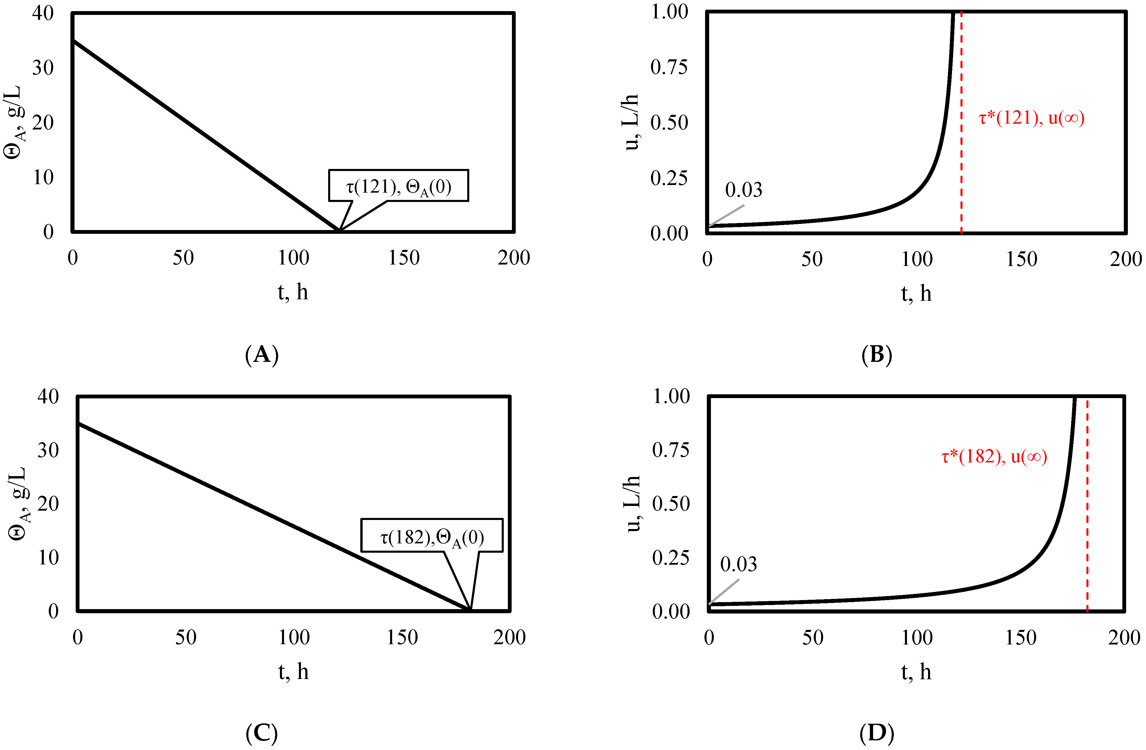
Then, in order to observe the behavior of the lubrication system without a control and with a regulator for different volumes of lubricant in the oil pan, simulations were carried out for 4 L and 6 L of lubricant in the oil pan. From these simulations, it was obtained that, on the one hand, the useful life of each load of lubricant for a lubrication system without a control, under the conditions of the simulations, is 54 h for 4 L of lubricant in the oil pan (Figure 6A,C) and 72 h for 6 L of lubricant in the oil pan (Figure 6B,D).On the other hand, the useful life of each load of lubricant for a lubrication system with a regulator, under the conditions of the simulations is 121 h for 4 L of lubricant in the oil pan (Figure 7A,C) and 182 h for 6 L of lubricant in the oil pan (Figure 7B,D).
Note that the difference in weight-volume ratio of lubricant precursors between the oil pan and the engine inside, for the lubrication system without a control, at the instant that the film thickness begins to decrease, θ A is 0.01 g/L for the three volumes of lubricant in the oil pan, 2, 4, and 6 L also note that the supply of lubricant u for the lubrication system with a regulator, at the initial instant, is 0.03 L/h for the three volumes of lubricant in the oil pan, 2, 4, and 6 L.
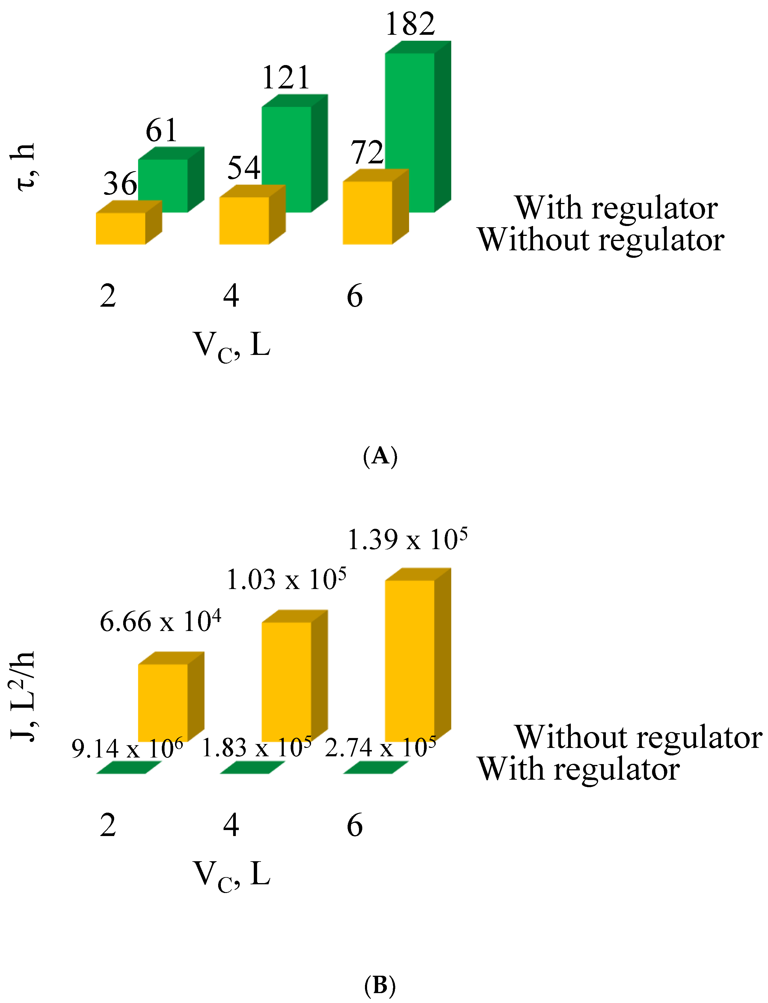
On the one hand, when comparing the useful life of each load of lubricant in the lubrication system with and without a control, it can be seen that the increase in the volume of lubricant that remains in the oil pan when the engine is working V C extends, as is logical, the duration of each load of lubricant, in both cases; however, it is appreciated that the useful life of the same load of lubricant in the crankcase is longer for the lubrication system with a regulator than for the lubrication system without a control; another important result is that the proportion of this increase in the service life is longer for larger volumes in the oil pan (Figure 8A). On the other hand, when comparing the performance index for the three volumes of lubricant in the oil pan, 2, 4, and 6 L, a very large difference can be seen between the indices of the lubrication system without a control and the indices of the lubrication system with a regulator (Figure 8B).
Last results reveal a very interesting situation, from the mathematical point of view, the regulation of the lubricant that pass through the engine may increases the life of each batch of lubricant, however to implement such regulation in real engines, some mechanical modifications and configurations are required for which development does not yet exist, therefore, there is still a lot of scientific and technologic work to be done to enhance the behavior of lubrication systems for combustion internal engines.

4.4. Results Discussion

In this work the solution of a problem related to internal combustion engines is presented from a completely mathematical approach, however this effort is only a step on the way to improve the performance of lubrication systems. Although, to obtain the results presented in this work, several not entirely realistic assumptions were made, the main contribution of this work is to show an area of opportunity to improve lubrication systems, from a mathematical point of view. The solution is very attractive, since it would reduce the net amount of lubricant consumed in lubrication systems for internal combustion engines and, consequently, the expenses associated with this consumption and the pollution resulting from its waste. It should be noted that the procedure to solve the mathematics involved in the model of the lubrication system are not trivial and require a real effort, yielding an innovative approach, in such a way that, currently, in most workshops of industries and companies related to internal combustion engines, the dynamics of the performance of lubricants in real engines is unknown; so, many times, it is decided to consume more lubricant to guarantee the protection of the engine, at the expense of money and pollution of the environment and, as indicated in the results of this work, such expenses could be excessive or unnecessary.
Even though, the results presented in this work cannot be applied directly to lubrication systems, these results do indicate that there are more efficient alternatives for the configuration of lubrication systems, which should be explored from both points of view, from the modeling and simulation to predict the regions of operation and from experimentation to demonstrate the technical feasibility of these regions of operation. In addition, these results raise new questions about lubrication systems for internal combustion engines, such as: Is it possible to increase the useful life of the lubricant without increasing engine wear? Is it possible to increase the useful life of the engines by using more lubricant? Is it possible to increase both engine and lubricant life by changing the lubricant supply configuration? Why or why not?
It cannot be denied that, in order to have a satisfactory answer to the above questions, a lot of experimental work and mathematical analysis is required, however, the work presented in this article is one of the possible starting points to answer some of those questions.

5. Conclusions

In this work, a modification of the lubrication system model developed by S. Dominguez-Garcia et al., 2022, which predicts the formation and remotion of tribofilm on internal surfaces of engine, was carried out by changing the variables of the mass balances. This modification allowed for implementing the optimal control methodology to this model of the lubrication system; then, both routes of operation of the lubrication system were computed by means of the RK4 method and the resulting lubricant life were compared, elucidating that the regulation of the lubricant flow sent to the engine maximizes the life of each batch of lubricant. This result is beyond the step in improving the lubrication system behavior presented by S. Dominguez-Garcia et al., 2022, where it is evidenced that the reduction of lubricant life in a lubrication system is due to high lubricant supply rates.
In addition to the previous general conclusion, the following particular conclusions are reached, which could be useful for future research:
The introduction of the variable of the difference in weight-volume ratio of lubricant precursors between the oil pan and the engine facilitated the solution of the system of differential equations that define the optimal route for the regulator of the lubricant supply to the engine inside.
For the solution of the mathematical problem resulting from the implementation of the optimal control methodology to the mathematical model of the lubrication system for internal combustion engines, based on the mass balances of lubricant precursors, it was not necessary to know the values of the adjoining variables, however, finding them ensures that the control route found is an optimal route.
Minimizing the supply of lubricant that is sent into the engine also results in maximizing the useful life of each lubricant charge. The increase in the useful life of each lubricant charge obtained through the implementation of a lubrication supply regulation system can be several times the useful life of the same lubrication charge used in a lubrication system without regulation, which works with a constant supply rate.
This knowledge can be very useful to reduce lubricant consumption and increasing sustainability by reducing lubricant costs and pollutant emissions of the lubricant waste coming from internal combustion engines still in use around the world.

Author Contributions

Conceptualization, S.D.-G., R.M.-Y. and F.N.-R.; methodology, S.D.-G.; validation, R.M.-Y. and A.L.-V.; resources, L.B.-G.; writing—original draft preparation, S.D.-G.; writing—review and editing, R.M.-Y., F.N.-R. and A.L.-V.; visualization, R.M.-Y. and L.B.-G. All authors have read and agreed to the published version of the manuscript.

Funding

This research received no external funding.

Data Availability Statement

The datasets generated during and/or analyzed during the current study are available from the corresponding author on reasonable request.

Acknowledgments

The authors gratefully thank CONACYT for sponsorship and grants and Universidad Michoacana de San Nicolás de Hidalgo for funding these studies.

Conflicts of Interest

The authors declare no conflict of interest.

References

  1. Pinheiro, C.; Ascensão, V.; Cardoso, C.; Quina, M.; Gando-Ferreira, L. An overview of waste lubricant oil management system: Physicochemical characterization contribution for its improvement. J. Clean. Prod. 2017, 150, 301–308. [Google Scholar] [CrossRef]
  2. Pires, A.; Martinho, G. Life cycle assessment of a waste lubricant oil management system. Int. J. Life Cycle Assess. 2013, 18, 102–112. [Google Scholar] [CrossRef]
  3. Cornelio, J.A.C.; Cuervo, P.A.; Hoyos-Palacio, L.M.; Lara-Romero, J.; Toro, A. Tribological properties of carbon nanotubes as lubricant additive in oil and water for a wheel–rail system. J. Mater. Res. Technol. 2016, 5, 68–76. [Google Scholar] [CrossRef] [Green Version]
  4. Zulhanafi, P.; Syahrullail, S. The tribological performances of Super Olein as fluid lubricant using four-ball tribotester. Tribol. Int. 2019, 130, 85–93. [Google Scholar] [CrossRef]
  5. Panda, J.N.; Bijwe, J.; Pandey, R.K. Particulate PTFE as a super-efficient secondary solid lubricant in PAEK composites for exceptional performance in adhesive wear mode. Compos. Part C Open Access 2021, 4, 100110. [Google Scholar] [CrossRef]
  6. Chowdary, K.; Kotia, A.; Lakshmanan, V.; Elsheikh, A.H.; Ali, M.K.A. A review of the tribological and thermophysical mechanisms of bio-lubricants based nanomaterials in automotive applications. J. Mol. Liq. 2021, 339, 116717. [Google Scholar] [CrossRef]
  7. Zhao, B.; Dai, X.-D.; Zhang, Z.-N.; Xie, Y.-B. A new numerical method for piston dynamics and lubrication analysis. Tribol. Int. 2016, 94, 395–408. [Google Scholar] [CrossRef]
  8. Fang, C.; Meng, X.; Xie, Y. A piston tribodynamic model with deterministic consideration of skirt surface grooves. Tribol. Int. 2017, 110, 232–251. [Google Scholar] [CrossRef]
  9. Akchurin, A.; Bosman, R.; Lugt, P.M. Generation of wear particles and running-in in mixed lubricated sliding contacts. Tribol. Int. 2017, 110, 201–208. [Google Scholar] [CrossRef]
  10. Akchurin, A.; Bosman, R.; Lugt, P.M.; van Drogen, M. On a Model for the Prediction of the Friction Coefficient in Mixed Lubrication Based on a Load-Sharing Concept with Measured Surface Roughness. Tribol. Lett. 2015, 59, 19. [Google Scholar] [CrossRef]
  11. Azam, A.; Dorgham, A.; Morina, A.; Neville, A.; Wilson, M.C. A simple deterministic plastoelastohydrodynamic lubrication (PEHL) model in mixed lubrication. Tribol. Int. 2019, 131, 520–529. [Google Scholar] [CrossRef] [Green Version]
  12. Ghanbarzadeh, A.; Wilson, M.; Morina, A.; Dowson, D.; Neville, A. Development of a new mechano-chemical model in boundary lubrication. Tribol. Int. 2016, 93, 573–582. [Google Scholar] [CrossRef]
  13. Azam, A.; Ghanbarzadeh, A.; Neville, A.; Morina, A.; Wilson, M.C. Modelling tribochemistry in the mixed lubrication regime. Tribol. Int. 2019, 132, 265–274. [Google Scholar] [CrossRef] [Green Version]
  14. Domínguez-García, S.; Maya-Yescas, R.; Béjar-Gómez, L. Reduction of lubricant life in lubrication systems for internal combustion engines due to high lubricant supply rates. Mater. Lett. 2022, 313, 131785. [Google Scholar] [CrossRef]
  15. Zhang, J.; Meng, Y. Boundary lubrication by adsorption film. Friction 2015, 3, 115–147. [Google Scholar] [CrossRef] [Green Version]
  16. Zhang, C. Analysis on mechanism of thin film lubrication. Chin. Sci. Bull. 2005, 50, 2645. [Google Scholar] [CrossRef]
  17. Harris, K.L.; Pitenis, A.A.; Sawyer, W.G.; Krick, B.A.; Blackman, G.S.; Kasprzak, D.J.; Junk, C.P. PTFE Tribology and the Role of Mechanochemistry in the Development of Protective Surface Films. Macromolecules 2015, 48, 3739–3745. [Google Scholar] [CrossRef]
  18. Cafolla, C.; Foster, W.; Voïtchovsky, K. Lubricated friction around nanodefects. Sci. Adv. 2020, 6, eaaz3673. [Google Scholar] [CrossRef] [Green Version]
  19. Yang, X.; Hu, Y.; Zhang, L.; Zheng, Y.; Politis, D.J.; Liu, X.; Wang, L.-L. Experimental and modelling study of interaction between friction and galling under contact load change conditions. Friction 2022, 10, 454–472. [Google Scholar] [CrossRef]
  20. Holmberg, K.; Ronkainen, H.; Laukkanen, A.; Wallin, K. Friction and wear of coated surfaces—Scales, modelling and simulation of tribomechanisms. Surf. Coat. Technol. 2007, 202, 1034–1049. [Google Scholar] [CrossRef]
  21. Söderfjäll, M.; Herbst, H.M.; Larsson, R.; Almqvist, A. Influence on friction from piston ring design, cylinder liner roughness and lubricant properties. Tribol. Int. 2017, 116, 272–284. [Google Scholar] [CrossRef]
  22. Domínguez-García, S.; Béjar-Gómez, L.; Huirache-Acuna, R.; Lara-Romero, J.; Maya-Yescas, R. Delumping Strategy to Infer Lubrication Reaction Pathways in Internal Combustion Engines. Int. J. Chem. React. Eng. 2020, 18, 20190043. [Google Scholar] [CrossRef]
  23. Domínguez-García, S.; Aguilar-Ramírez, C.E.; Béjar-Gómez, L.; Maya-Yescas, R. Mass balance of the tribofilm in lubricated systems. Tribol. Int. 2021, 155, 106757. [Google Scholar] [CrossRef]
  24. Acharya, B.; Seed, C.M.; Krim, J. Shear activation of ZDDP reaction films in the presence and absence of nanodiamonds. Appl. Surf. Sci. Adv. 2022, 7, 100214. [Google Scholar] [CrossRef]
  25. Spikes, H. The History and Mechanisms of ZDDP. Tribol. Lett. 2004, 17, 469–489. [Google Scholar] [CrossRef]
  26. Minfray, C.; Martin, J.M.; de Barros, M.I.; le Mogne, T.; Kersting, R.; Hagenhoff, B. Chemistry of ZDDP tribofilm by ToF-SIMS. Tribol. Lett. 2004, 17, 351–357. [Google Scholar] [CrossRef]
  27. Ueda, M.; Kadiric, A.; Spikes, H. On the Crystallinity and Durability of ZDDP Tribofilm. Tribol. Lett. 2019, 67, 123. [Google Scholar] [CrossRef] [Green Version]
  28. Shimizu, Y.; Spikes, H. The Influence of Slide–Roll Ratio on ZDDP Tribofilm Formation. Tribol. Lett. 2016, 64, 19. [Google Scholar] [CrossRef] [Green Version]
  29. Shimizu, Y.; Spikes, H. The Tribofilm Formation of ZDDP Under Reciprocating Pure Sliding Conditions. Tribol. Lett. 2016, 64, 46. [Google Scholar] [CrossRef] [Green Version]
  30. Muraki, M.; Yanagi, Y.; Sakaguchi, K. Synergistic effect on frictional characteristics under rolling-sliding conditions due to a combination of molybdenum dialkyldithiocarbamate and zinc dialkyldithiophosphate. Tribol. Int. 1997, 30, 69–75. [Google Scholar] [CrossRef]
  31. Persson, B. Contact mechanics for randomly rough surfaces. Surf. Sci. Rep. 2006, 61, 201–227. [Google Scholar] [CrossRef] [Green Version]
  32. Bonaventure, J.; Cayer-Barrioz, J.; Mazuyer, D. Transition Between Mixed Lubrication and Elastohydrodynamic Lubrication with Randomly Rough Surfaces. Tribol. Lett. 2016, 64, 44. [Google Scholar] [CrossRef]
  33. Petrova, D.; Weber, B.; Allain, C.; Audebert, P.; Venner, C.H.; Brouwer, A.M.; Bonn, D. Fluorescence microscopy visualization of the rough-ness-induced transition between lubrication regimes. Sci. Adv. 2019, 5, eaaw4761. Available online: https://www.science.org (accessed on 1 January 2022). [CrossRef] [PubMed] [Green Version]
  34. Khaemba, D.N.; Jarnias, F.; Thiebaut, B.; Neville, A.; Morina, A. The role of surface roughness and slide-roll ratio on the decomposition of MoDTC in tribological contacts. J. Phys. D Appl. Phys. 2017, 50, 085302. [Google Scholar] [CrossRef] [Green Version]
  35. Lewis, F.L.; Vrabie, D.; Syrmos, V.L. Optimal Control; John Wiley & Sons: Hoboken, NJ, USA, 2012. [Google Scholar]
  36. Domínguez-García, S.; Béjar-Gómez, L.; Nápoles-Rivera, F.; Maya-Yescas, R. Optimal Control of Make-up Lubricating Systems for Internal Combustion Engines. ACAM 2021, 4, 74. [Google Scholar] [CrossRef]
  37. Göllmann, L.; Kern, D.; Maurer, H. Optimal control problems with delays in state and control variables subject to mixed control-state constraints. Optim. Control Appl. Methods 2009, 30, 341–365. [Google Scholar] [CrossRef]
  38. Alt, W.; Schneider, C. Linear-quadratic control problems withL1-control cost. Optim. Control Appl. Methods 2015, 36, 512–534. [Google Scholar] [CrossRef]
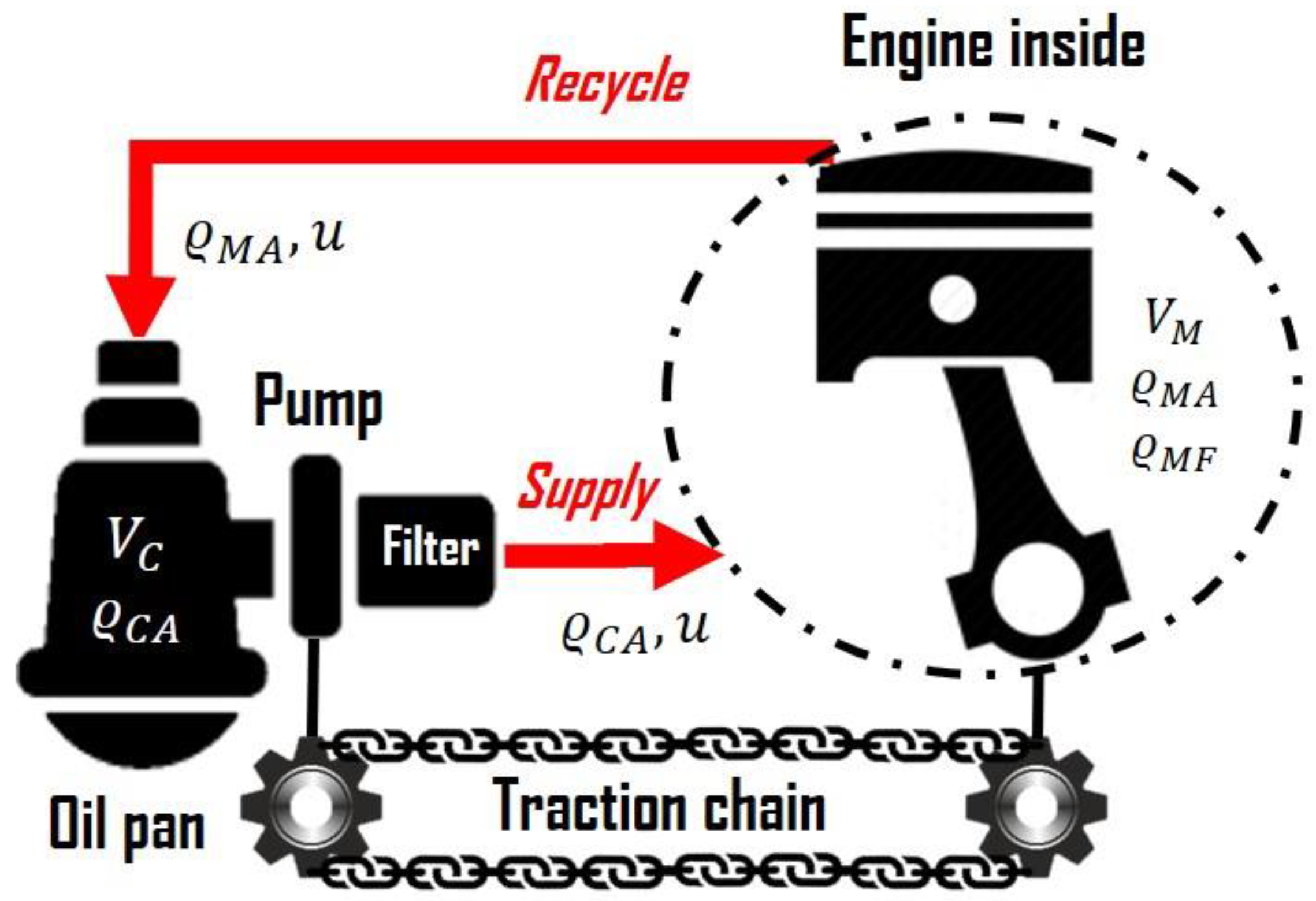
Figure 1. Functional diagram of the lubrication system.
Processes 10 02070 g001
Figure 2. (A) Growth restrictions of the tribofilm and (B) Reactive scheme of tribofilm formation.
Processes 10 02070 g002
Figure 3. Scheme of the methodology to find out the optimal regulated route and to compare it versus the unregulated route.
Processes 10 02070 g003
Figure 4. Route of the state of lubrication system without a regulator for 2 L of lubricant in oil pan. (A) Tribofilm thickness profile and (B) profile of the difference in partial densities of lubricant precursors between the crankcase and the engine.
Processes 10 02070 g004
Figure 5. Route of the state of lubrication system with a regulator for 2 L of lubricant in oil pan. (A) Profile of the difference in partial densities of lubricant precursors between the crankcase and the engine and (B) Optimal route of lubricant supply to the interior of the engine.
Processes 10 02070 g005
Figure 6. Route of the state of lubrication system without a regulator. (A) Tribofilm thickness profile for 4 L of lubricant in the oil pan, (B) Tribofilm thickness profile for 6 L of lubricant in the oil pan, (C) Profile of the difference in partial densities of lubricant precursors between the oil pan and the engine for 4 L of lubricant in the oil pan, and (D) Profile of the difference in partial densities of lubricant precursors between the oil pan and the engine for 6 L of lubricant in the oil pan.
Processes 10 02070 g006
Figure 7. Route of the state of lubrication system with a regulator. (A) Profile of the difference in partial densities of lubricant precursors between the oil pan and the engine for 4 L of lubricant in the oil pan, (B) Profile of the difference in partial density of lubricant precursors between the oil pan and the engine for 6 L of lubricant in the oil pan, (C) Optimal lubricant supply path to the inside of the engine for 2 L of lubricant in the oil pan, and (D) Optimal lubricant supply path to the inside of the engine for 6 L of lubricant in the oil pan.
Processes 10 02070 g007
Figure 8. Comparison of the lubrication system with and without the regulator of the lubricant supply to inside the engine. (A) Comparison of the useful life of each load of lubricant and (B) Comparison of the performance index.
Processes 10 02070 g008
Publisher’s Note: MDPI stays neutral with regard to jurisdictional claims in published maps and institutional affiliations.