Article

Analytical Research on the Bearing Characteristics of Oil Film Supplied with Constant Oil Flow Hydrostatic Turntables under Fixed Eccentric Load Condition

1
Hunan Province Engineering Laboratory of Wind Power Operation Maintenance and Testing Technology, College of Mechanical Engineering, Hunan Institute of Engineering, Xiangtan 411104, China
2
Harbin Electric Wind Power Research Institute, Xiangtan 411104, China
3
School of Mechanical Engineering, Hunan University of Science and Technology, Xiangtan 411201, China
*
Author to whom correspondence should be addressed.
Processes 2022, 10(10), 2017; https://doi.org/10.3390/pr10102017
Submission received: 1 August 2022 / Revised: 24 September 2022 / Accepted: 25 September 2022 / Published: 6 October 2022

Abstract

:
This study was initiated in view of the phenomenon that hydrostatic turntable rails are prone to scrape damage when the liquid hydrostatic turntable is running under fixed partial load. The existing bias-load hydrostatic turntable oil film bearing characteristics are mainly calculated by using the calculus integration method and CFD fluid simulation method. The calculating formula obtained by the calculus integration method is complex and inefficient. The CFD fluid simulation calculation method requires 3D modeling and meshing of the oil film, which is a tedious and time-consuming process and may not yield convergent calculation results due to improper meshing methods or boundary condition settings. In order to solve the shortage of the above calculation methods, this paper simplifies and equates the uneven thickness of the oil film of each sealing edge of the oil pad of the bias-loaded hydrostatic rotary table to the equivalent uniform thickness of the oil film, and based on this idea, the analytical calculation formula of the oil film bearing capacity, bending moment and stiffness under constant bias-load conditions of the constant-flow liquid hydrostatic rotary table is derived. In this paper, Fluent software was used to numerically simulate the oil film under this working condition, and a hydrostatic turntable test bench was established to conduct an experimental study on the biased load hydrostatic turntable; the experimental data and simulation results were compared with the results obtained from this simplified method of calculating the oil film loading characteristics. The results show that the error of oil film bearing capacity is less than 6% and the error of overturning moment is less than 7%, which has verified the validity of the calculation method. The simplified analytical calculation method proposed in this paper is used to study the influence of tilt displacement rate, lubricant flow rate and turntable speed on the basic performance parameters of oil film, which provides a theoretical basis for the study of oil film load-bearing characteristics under constant bias-load conditions of the constant-flow liquid hydrostatic turntable.

1. Introduction

The constant flow oil supply hydrostatic turntable (hydrostatic turntable) has the advantages of high rotation accuracy, high stiffness, large bearing capacity, strong anti-overturning stability, and so on, and is widely used in precision and ultra-precision heavy-duty vertical machine tools. When the hydrostatic turntable is working, it is influenced by factors such as workpiece shape and clamping position, which makes the rotary table tilted by uneven force, and the oil film height is no longer equal everywhere. The processing quality will be lowered, and even the turntable may be scratched and damaged, resulting in accidents under the eccentric load condition. Therefore, studying the oil film bearing characteristics of the static pressure turntable under eccentric load conditions plays critical roles in solving the scratch accident of the hydrostatic turntable, which has notable engineering practical value.
Recently, a few scholars at home and abroad have studied the bearing characteristics of hydrostatic turntables under a fixed eccentric load condition. Ma, L. et al. [1] used Fluent software to simulate the relationship between pressure, piston rod speed, eccentricity, partial load and asymmetric hydrostatic bearing oil film performance. Wang, L. et al. [2] deduced the relationship between hydrodynamic and thermal coupling on pressure distribution and load carrying capacity of the circular oil pad, based on Christensen’s stochastic model of rough surface. Kozdera, M. et al. [3] analyzed the relationship between the pressure field, load carrying capacity and static pressure variation of annular hydrostatic thrust bearings. However, none of them gave an intuitive analytical formula for calculation. Rehman, W.U. et al. [4] developed a mathematical model and robust control design system and used fractional-order control techniques and optimization algorithms to improve the static–dynamic characteristics of actively controlled hydrostatic bearings. Alves, D.S. et al. [5] introduced the oil film nonlinear characteristics by creating an analytical model. Liu, C. et al. [6] used the FSI technique and computational fluid dynamics (CFD) method to develop a novel flow–structure–thermal coupling model to study the hydrostatic rotary table under different operating conditions. Andrés, L.S. et al. [7] developed a large volume flow model of axial clearance of hydrostatic thrust bearing with supply pressure, load and flow resistance of the membrane surface. Liu, Z. et al. [8] studied the coupling characteristics of tilting and thermal effects and found that tilting has a huge effect on the groove pressure, load capacity and stiffness of hydrostatic bearings. Dong, X. et al. [9] established the Reynolds equation for oil film solved by the finite difference method and continuous over-relaxation iterative algorithm and numerically analyzed the oil film characteristics of circular oil pad and annular oil pad. Li, M. et al. [10] studied the lubrication performance of hydrostatic thrust bearings of heavy/large equipment based on large circular oil pads and established a mathematical model for the distribution of lubrication performance such as velocity field, flow field and pressure field. However, these experiments did not investigate the sectoral multi-pad planar hydrostatic thrust bearings. Gao, Q. et al. [11] uses fractional-order control techniques and optimization algorithms to improve the static–dynamic characteristics of actively controlled hydrostatic bearings. Yu, X. et al. [12] constructed a mathematical model of the relationship between rotational speed and load carrying capacity of a double rectangular hydrostatic bearing and analyzed the load and rotational speed characteristics of the temperature and pressure fields of the hydrostatic bearing oil film. Liu, Z. et al. [13] proposed an analytical calculation method to determine the load carrying capacity and moment of a circular oil pad. Liang, P. et al. [14] proposed a new analytical method to calculate the static performance of hydrostatic radial bearings. However, only the notch pressure and flow rate at the same eccentricity and oil notch wrapping angle are involved. Hsiao, S.T. et al. [15] used the flow resistance network method to analyze the bearing carrying load capacity. Wu, L. [16] used CFD method to model the oil film in the hydrostatic bearing of a gear pump operating at high pressure and speed. However, these studies did not conduct a comprehensive study of the pressure, flow and load carrying capacity of the bearings. Bouyer, J. et al. [17] experimented with steady-state and transient bearing operation. The speed was found to be a critical parameter: as it increases, the hydrostatic pressure effect is affected, and the film thickness decreases. Gao, S. et al. [18] analyzed the effects of hydrostatic thrust bearing load capacity, stiffness, volumetric flow rate and orifice flow resistance. Yu, X. et al. [19] derived the load carrying capacity, flow rate, oil film thickness equation and oil film stiffness of hydrostatic-pressure hybrid bearings under variable viscosity conditions, based on tribological principles and lubrication theory. Tian, Z. et al. [20] discussed the static characteristics of hydrostatic thrust bearings by considering the inertia effect in the area of the oil supply hole. In turn, new expressions for pressure, load capacity and flow rate are given. Zhang, Y. et al. [21] proposed a new method for calculating the oil film temperature, considering the effect of hot oil carryover, and analyzed the effect of some parameters on the temperature distribution. In Zhang, Y. et al. [22], a mathematical model of the lubrication characteristics of a vertical hydrostatic guideway is established, and the relationship between the groove pressure and the oil film thickness is derived. Zhang, Y. et al. [23] also constructed a mathematical model of the bearing characteristics of a multi-oil pad hydrostatic bearing. Based on the idea of equivalent oil film thickness, Our Subject Group [24] proposed an analytical formula for the load-bearing characteristics such as oil film load capacity, bending moment and stiffness of a liquid hydrostatic rotary table with a small orifice throttling ring in constant pressure supply under biased load conditions. However, they are not applicable to constant flow liquid hydrostatic rotary tables for off-load conditions. Zhao, J. et al. [25] studied the effect of machining and assembly tolerances on the performance of the turntable. The hydrostatic oil film is assumed as the elastomer in this paper; the load-bearing capacity of oil pockets with table mass offset was studied. The effect of machining tolerance of oil seal with gap on the load-bearing capacity of the oil bag is analyzed.
In summary, the hydrostatic turntable oil film load-bearing characteristics under constant bias load conditions can be studied by the micro-integral calculation method and CFD fluid simulation calculation method. The calculating formula obtained by the calculus integration method is complex and inefficient. The CFD fluid simulation calculation method requires 3D modeling and meshing of the oil film, which is a tedious and time-consuming process and may not yield convergent calculation results due to improper meshing methods or boundary condition settings.
In view of the shortcomings of the above methods for calculating the oil film bearing characteristics of hydrostatic turntables under fixed bias load conditions, this paper simplifies and equates the uneven thickness of the oil film of each sealing edge of the hydrostatic turntable oil pad to a uniform equivalent oil film and derives the analytical formula for calculating the oil film bearing capacity, bending moment and stiffness under constant bias load conditions of hydrostatic turntables with constant flow, based on this idea. In this paper, Fluent software was used to numerically simulate the oil film under this working condition; a hydrostatic turntable test system was established, and an experimental study was conducted on the biased load hydrostatic turntable; the experimental data and simulation results were compared with the results obtained from this simplified method of calculating the oil film bearing characteristics, and the validity of the calculation method was verified.

2. Analytical Calculation Method for the Bearing Characteristics of Oil Film Supplied with Constant Oil Flow Hydrostatic Turntables under Fixed Eccentric Load Condition, Based on Equivalent Oil Film Thickness
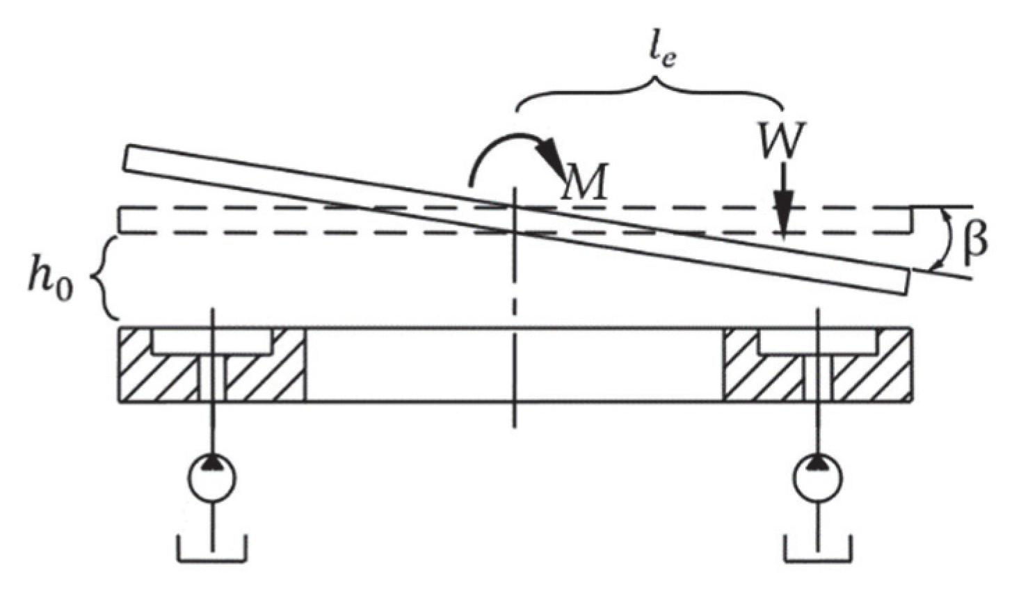
This paper analyzes the physical model of tilted oil film of the liquid hydrostatic turntable under a fixed bias load condition, equates the uneven thickness oil film of each sealing edge of the hydrostatic turntable oil pad to the equivalent uniform thickness oil film, and establishes a simplified analytical calculation mathematical model of tilted oil film bearing characteristics under a bias load condition of the liquid hydrostatic turntable based on this idea.

2.1. Physical Model

The quantitative pump will pump the lubricant from the oil tank and provide the lubricant to the oil chamber through the inlet hole of each oil chamber. When the lubricating oil film pressure on the surface of the hydrostatic guide is greater than the turntable gravity, the liquid hydrostatic turntable floats up, and the upper and lower hydrostatic guide surfaces are in a pure liquid friction state. The lubricating oil flows back to the oil tank through the gap of the sealing oil edge. As shown in Figure 1, hydrostatic turntables are affected by the shape of the workpiece and of clamping position during operation, so that the turntable is subjected to overturning torque, and the shape of the oil film changes.
According to the force translation theorem, load-bearing force of the hydrostatic turntable can be decomposed into an axial force W and an overturning moment M = W l e , where eccentricity l e is the distance from the center of gravity of the workpiece to the center of the turntable. If only axial force W is applied, the table translates to the base of the guide at a distance e w . The overturning moment M acts to tilt the turntable, changing distribution of the load in each oil chamber. h 0 is the distance from the center of the turntable circle to the center of the lower circular guide, β is the tilt angle of the turntable, and e M is the maximum offset of displacement. Tilt displacement rate at the maximum displacement of the turntable is ε M = e M / h 0 . As shown in Figure 1, biased load turntable tilt direction is x-axis direction. φ i is the angle between the x-axis direction and the symmetrical centerline of the oil pad (the angle between the x-axis direction and the centerline of symmetry of the oil pad).
The subscript i is the oil pad number. The oil pad intersecting the x-axis in the positive direction is defined as No. 1, and along the counterclockwise direction is defined as No. 2, 3, 4, … in that order. As shown in Figure 2, φ i , φ i 1 , φ i 2 , φ i 3 , φ i 4 , φ i 5 , φ i 6 indicate the angles of each position in the i-th oil pad with respect to the x-axis (i = 1, 2, 3, …, n, n is the number of oil pads) [26,27,28,29].
For this physical model, the following assumptions are made: (1) The lubricant flow state is laminar flow. (2) Contact between lubricant and wall is without slip. (3) The quality force of the lubricant is tiny relative to the shear force and ignored. (4) The pressure, density and viscosity of the lubricant remain constant along the direction of oil film thickness. (5) Only the velocity gradient along the direction of the oil film thickness is large and the others can be ignored, when the lubricant flows. (6) The oil film thickness is little compared with the radius of the oil pad, so the curvature of the oil film is neglected. The speed of movement can be replaced by the speed of rotation.

2.2. Calculus Approach

The oil pads are separated from each other by oil return grooves, and each oil pad is independent of each other. One of the individual sector oil pads in the annular oil pad hydrostatic bearing is shown in Figure 2. θ 1 is half of the corresponding circle angle of the sector-shaped oil pad, θ 2 is half of the corresponding circle angle of the sector-shaped oil chamber. The half of the circle center angle corresponding to the effective bearing area of the oil pad derived from the simplified calculation is set as θ e . In Figure 2 and Figure 3, θ 1 and θ 2 are known parameters, φ i , φ i 1 , φ i 2 , φ i 3 , φ i 4 , φ i 5 , φ i 6 , θ e are expressions about known parameters. The relationship between the parameters can be found as follows:
φ i = 2 π ( i 1 ) / n + φ 0 , φ i 1 = φ i 0.5 θ 1 ,
φ i 2 = φ i 0.5 θ 2 , φ i 3 = φ i + 0.5 θ 2 φ i 4 = φ i + 0.5 θ 1 , φ i 5 = φ i 0.5 θ e ,
φ i 6 = φ i + 0.5 θ e , θ e = θ 1 + θ 2 / 2 .
Length in the circumferential direction of the straight sealing edge (No. 1 and No. 2 sealing edge):
L = 1 2 R θ 1 θ 2
Equivalent radius:
R e = ( R e 1 + R e 2 ) / 2
The uneven thickness oil film of each sealing edge of the hydrostatic turntable oil pad is equated to the equivalent of uniform thickness oil film. In view of the problem of calculating the load-bearing characteristics of the inclined oil film of a biased-load hydrostatic turntable, a simplified method of calculating the equivalent oil film thickness is adopted, based on the previous differential integration method.
Equivalent oil film thickness is the volume of oil film on each sealing edge of inclined oil film divided by the corresponding sealing edge area; calculation formula is: h e = S h d S / S d S (S is the area of the corresponding sealing edge). The method of calculating the oil film bearing characteristics of an off-load hydrostatic turntable using equivalent oil film thickness is called the equivalent oil film thickness method. This method equates each sealing edge gap to a parallel flat slit of equivalent oil film thickness, thereby simplifying the equation for calculating the oil film loading characteristics of a hydrostatic turntable under constant bias load conditions.
(1)
Equivalent oil film thickness of any oil pad sealing oil edge
Integrate the face of any oil pad No. 1 sealing edge corresponding to the hydrostatic guide:
R 1 R 4 φ i 1 φ i 2 r d φ d r = φ i 2 φ i 1 R 4 2 R 1 2 / 2
Integrate the body between the upper and lower two descending guides corresponding to the oil sealing edge of any oil pad No. 1:
R 1 R 4 φ i 1 φ i 2 h r d φ d r = h 0 φ i 2 φ i 1 R 4 2 R 1 2 / 2 sin φ i 2 sin φ i 1 tan α R 4 3 R 1 3 / 3
The equivalent oil film thickness of any oil pad No. 1 sealing edge:
h e i 1 = R 1 R 4 φ i 1 φ i 2 h r d φ d r R 1 R 4 φ i 1 φ i 2 r d φ d r = h 0 2 sin φ i 2 sin φ i 1 tan α R 1 2 + R 1 R 4 + R 4 2 3 φ i 2 φ i 1 R 1 + R 4
where subscript e —Equivalent oil film thickness mark; subscript   i —Oil pad number mark; subscript 1—No. 1 oil sealing edge of the i-th oil pad.
In the same way:
h e i 2 = R 1 R 4 φ i 3 φ i 4 h r d φ d r R 1 R 4 φ i 3 φ i 4 r d φ d r = h 0 2 sin φ i 4 sin φ i 3 tan α R 1 2 + R 1 R 4 + R 4 2 3 φ i 4 φ i 3 R 1 + R 4
h ei 3 = R 3 R 4 φ i 1 φ i 4 h r d φ d r R 3 R 4 φ i 1 φ i 4 r d φ d r = h 0 2 tan α sin φ i 4 sin φ i 1 R 3 2 + R 3 R 4 + R 4 2 3 φ i 4 φ i 1 R 3 + R 4
h ei 4 = R 1 R 2 φ i 1 φ i 4 h r d φ d r R 1 R 2 φ i 1 φ i 4 r d φ d r = h 0 2 tan α sin φ i 4 sin φ i 1 R 1 2 + R 1 R 2 + R 2 2 3 φ i 4 φ i 1 R 1 + R 2
(2)
Flow Rate of any oil pad sealing oil edge
In consideration of the liquid hydrostatic turntable speed, the flow rate of each sealing edge of any oil pad is calculated according to the formula of fluid flow rate between parallel flat gaps as [30]:
Q i 1 = b h e i 1 3 12 μ L Δ p i 1 2 b h e i 1 ω R e
Δ p i —Pressure difference between the inside of the i-th oil chamber and the atmosphere
μ—Lubricant viscosity
ω —Turntable speed
Q i 2 = b h ei 2 3 12 μ L Δ p i + 1 2 b h e i 2 ω R e
Q i 3 = θ θ h e i 3 3 6 μ ln R 4 / R 3 Δ p i + θ e h e i 3 3 6 μ ln R 4 / R 3 0.15 ρ ω 2 R 4 2 R 3 2
Q i 4 = θ θ h e i 4 3 6 μ ln R 2 / R 1 Δ p i θ e h e i 4 3 6 μ ln R 2 / R 1 0.15 ρ ω 2 R 2 2 R 1 2
Based on the above equation, the oil supply quantity of any oil pad is:
Q i 0 = Q i 1 + Q i 2 + Q i 3 + Q i 4 = ( C i 11 + C i 21 + C i 31 + C i 41 ) Δ P i + ( C i 12 + C i 22 + C i 32 + C i 42 )
where C i 11 = b h e i 1 3 12 μ L ; C i 12 = 1 2 b h e i 1 ω R e ; C i 21 = b h e i 2 3 12 μ L ; C i 22 = 1 2 b h e i 2 ω R e ; C i 31 = θ e h e i 3 3 6 μ ln R 4 / R 3 ; C i 32 = θ θ h e i 3 3 6 μ ln R 4 / R 3 0.15 ρ ω 2 R 4 2 R 3 2 ; C i 41 = θ e h e i 4 3 6 μ ln R 4 / R 3 ; C i 42 = θ θ h e i 4 3 6 μ ln R 2 / R 1 0.15 ρ ω 2 R 2 2 R 1 2 .
(3)
Bearing characteristics of oil film supplied with constant oil flow hydrostatic turntables after simplifying the analytical formalism
(a)
Bearing capacity of the entire oil film
Q i 0 is always a certain value for a constant flow supply of hydrostatic turntable [31].
When the oil film thickness is certain, the pressure in any oil chamber is:
Δ p i = Q i 0 C i 12 + C i 22 + C i 32 + C i 42 C i 11 + C i 21 + C i 31 + C i 41
The effective bearing area of the fan-shaped oil pad is:
A e = θ e 2 R e 2 2 R e 1 2
The bearing capacity of the whole oil pad is:
W = i = 1 n Δ p i A e
(b)
Stiffness of the entire oil film
K = F h 0
(c)
Overturning moment of the entire oil film
As shown in Figure 1, the hydrostatic turntable is tilted around the y-axis. Therefore, the oil film overturning moment is along the y-axis direction.
Effective bearing area inner circle radius [30]:
R e 1 = R 2 1 R 1 / R 2 2 2 ln R 2 / R 1
Effective bearing area outer circle radius [30]:
R e 2 = R 4 1 R 3 / R 4 2 2 ln R 4 / R 3
Effective radial width (difference between effective inner and outer radius):
b = R e 2 R e 1
Overturning moment of the arbitrary oil pad is:
M i = R e 1 R e 2 φ i 5 φ i 6 p i r cos φ r d φ d r = p i sin φ i 6 sin φ i 5 R e 2 3 R e 1 3 / 3
So, overturning moment of the whole oil film is:
M = i = 1 n M i

3. CFD Simulation Calculation

For a typical model of the liquid hydrostatic rotary table under different tilt displacement rate working conditions, this paper adopts the most comprehensive and widely adaptable Fluent software to numerically simulate the bearing force and overturning moment of the oil film under this working condition. At the same time, the hydrostatic turntable test system was established to conduct experimental studies on the biased hydrostatic turntable. The simulation results and experimental data are compared with the results obtained by this simplified method of calculating the equivalent oil film thickness of oil film load characteristics to verify the effectiveness of this calculation method.
The following basic assumptions were made in conducting the numerical simulations: ① Lubricants are considered incompressible fluids. ② No relative sliding occurs between lubricant and solid. ③ Lubricant outlet pressure is zero. ④ Laminar flow of lubricant exists inside the bearing. ⑤ Ignore the force and heat deformation of lubricant and solid base boundary.
A typical model of liquid hydrostatic turntable lubricant pad related parameters are as follows:
φ 5 = 0 , θ 1 = 26 , θ 2 = 18 , R1 = 850 mm, R2 = 917 mm, R3 = 83 mm, R4 = 1050 mm, L = 436.46 mm, b = 66 mm.
This model of hydrostatic turntable uses No. 46 lubricant. When the density ρ = 0.917 × 10 3 Kg / m 3 and the temperature is 30 °C, the kinematic viscosity η = 0.0688 Kg / ( m s ) .
The pre-processing software ICEM was used to model the fluid. Considering the accuracy of the calculation results and the requirements, such as the number of meshes, the fluid region is divided by a hexahedral regular mesh, as shown in Figure 4. The oil film thickness direction is divided into 8 layers, the oil film surface is divided by quadrilateral, the body mesh is in pave mode, and the number of fluid domain mesh nodes is about 1.15 million. Additionally, we set the corresponding boundary conditions as follows: the inlet hole is defined as the velocity inlet, the inner and outer cylindrical surfaces of the oil film is defined as the pressure outlet, the upper surface of the oil film is the rotating wall surface, and the others are the wall surfaces.
Fluent software was used to solve the model. The solver is a single-precision split solver; the SIMPLE algorithm is chosen to solve the problem in the standard format, and the second-order windward format is chosen for the discrete format of the momentum. The following convergence criterion is set, and the relative errors in solving the control parameter equations are all 1 × 10⁻³, and the under-relaxation factors of pressure and velocity are all 0.3 and others are 1. The specific parameters of the boundary conditions are set as follows: the inlet oil supply speed is 0.1061 m/s (total flow rate is 6 L/min) and the outlet pressure is 0 MPa. As shown in Figure 5, the pressure distribution cloud of the oil film is at the center height of 0.15 mm and the tilt displacement rate of 0.1.

4. Experimental Analysis

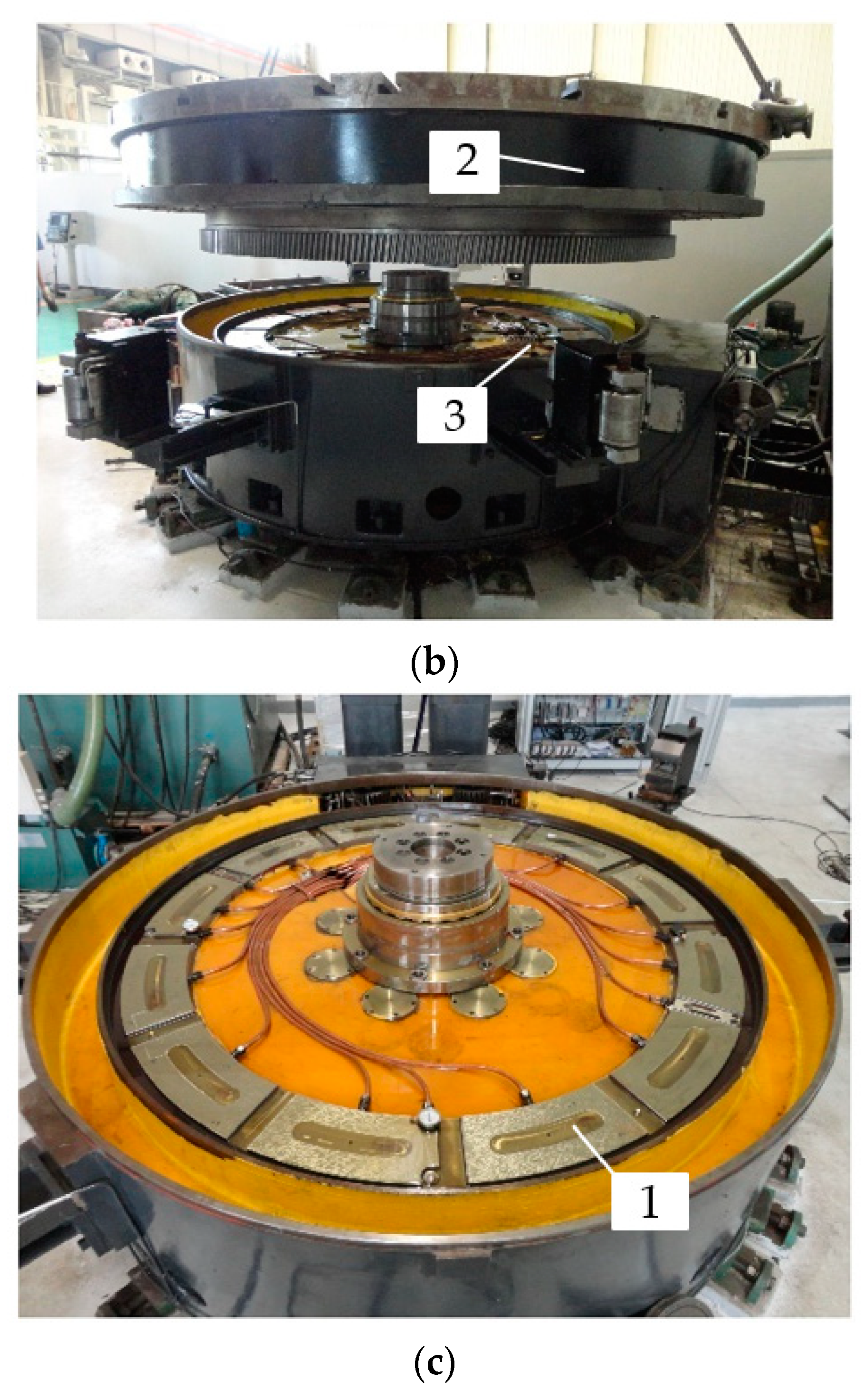
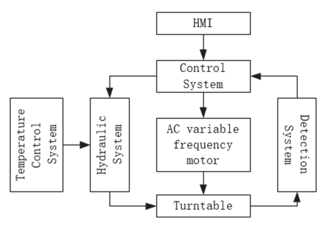
4.1. Experimental Program

As shown in Figure 6, in order to further verify the reliability of the method of calculating the equivalent oil film thickness of the oil film bearing characteristics of the liquid hydrostatic turntable under fixed bias load conditions, a heavy-duty vertical CNC lathe hydrostatic turntable test system was constructed. The system consists of a hydrostatic turntable, temperature control system, hydraulic system, power system, detection system and control system.
The operating principle of the heavy-duty hydrostatic rotary table test system is shown in Figure 7. The temperature of the lubricating oil in the tank is controlled by a temperature control system. Lubricating oil flows into the hydrostatic turntable guide the oil chamber through the hydraulic system to provide lubrication for the spindle and keep the liquid hydrostatic turntable in a hydrostatic working condition. Lubricating oil flows out through the oil side of the hydrostatic guide seal and then flows back to the tank through the hydraulic system. The control system controls the lubricant flow and rotary table speed by controlling the frequency of the two inverter motors that drive the oil supply pump and the rotary table. The main parameters of the real-time working status of the hydrostatic turntable (oil film thickness, rail temperature, pressure in the oil chamber) are monitored by the monitoring system and transformed into electrical signals for input to the control system and are controlled in real time according to the working requirements for early warning or shutdown protection in case of emergency. The HMI allows the user to program and operate the hydrostatic turntable and to read the relevant values directly.
Experimental conditions: the flow rate of oil supplied to the turntable by the control dosing pump is 6 L/min and the speed of the turntable is 20 r/min. The weight of the turntable is 9.4 t.
Data acquisition: Based on the maximum oil film thickness and minimum oil film thickness monitored by the four displacement sensors, the average maximum oil film thickness and average minimum oil film thickness are found out, respectively, and the tilt displacement rate is calculated. The load carrying force is the sum of the load gravity and the self-weight of the rotary table. The overturning moment is obtained from the load gravity and eccentric displacement.

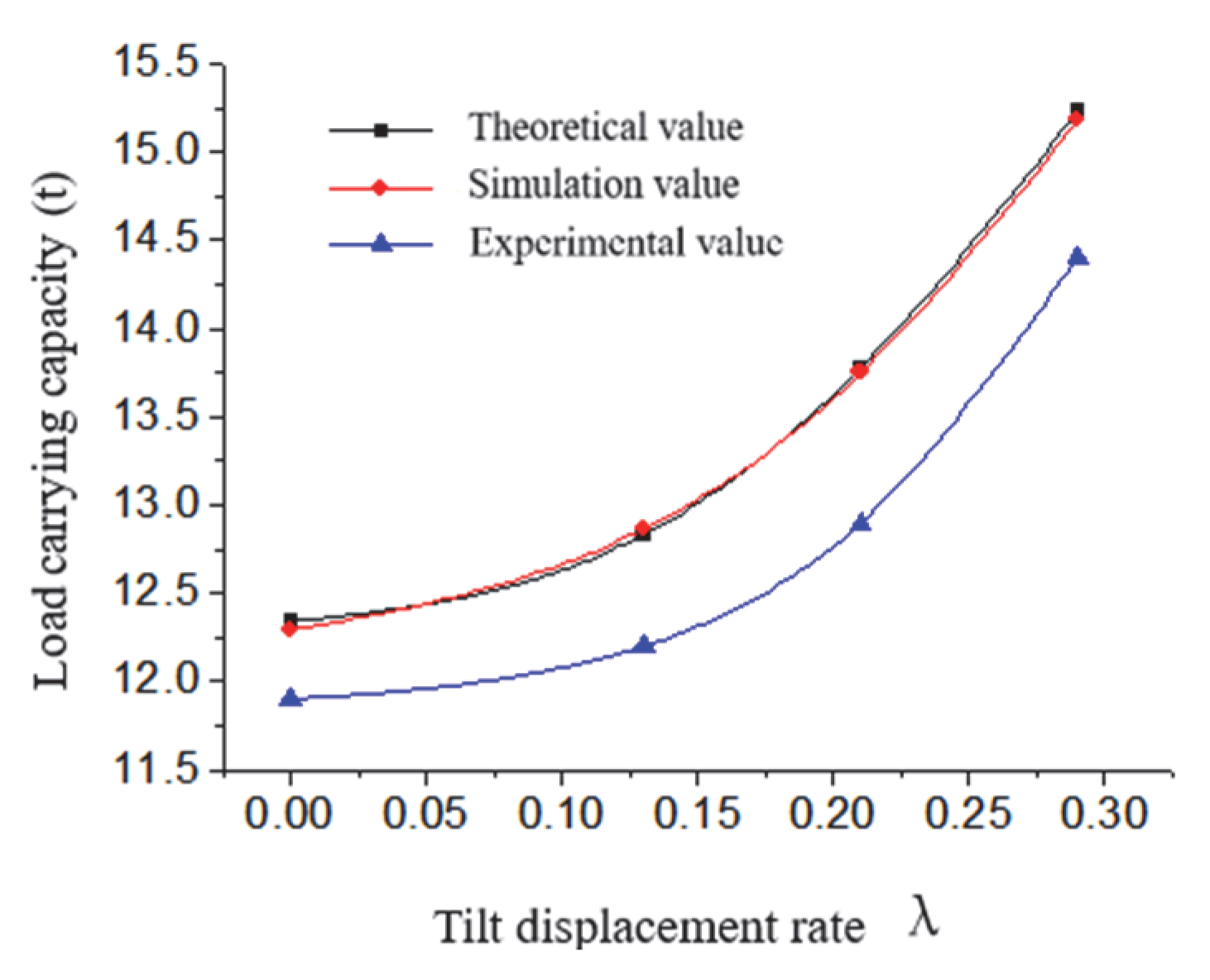
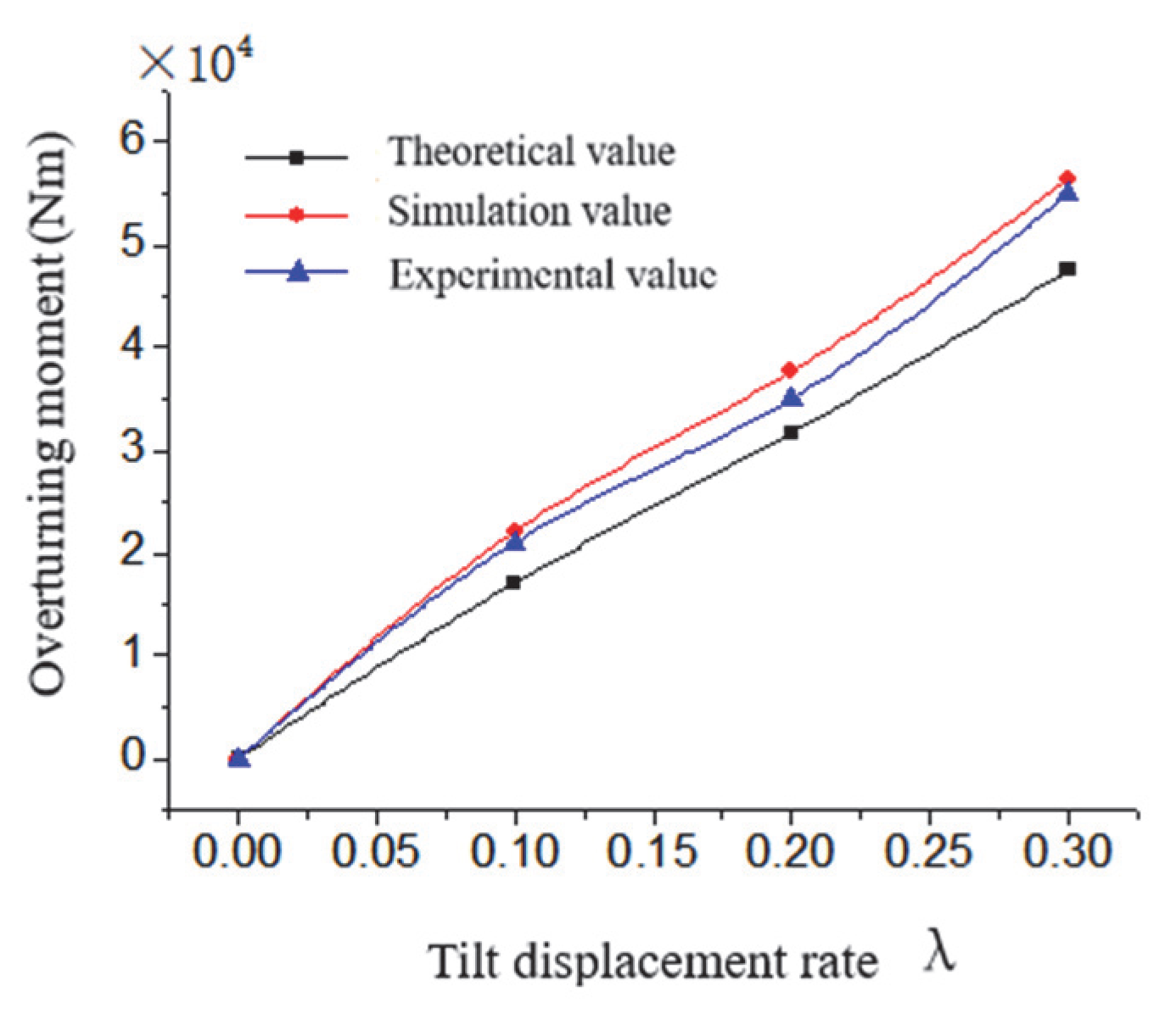
4.2. Analysis of Experimental Results

The experimental data, simulation calculation results and the results obtained by the equivalent film thickness calculation method of the bias-loaded liquid hydrostatic turntable load bearing characteristics proposed in this paper are compared and analyzed to verify the feasibility and effectiveness of the calculation method.
It is difficult to conduct experimental studies on heavy-duty hydrostatic rotary tables with deflection loads. On the one hand, a load of tens or even hundreds of tons is required to produce a large tilt displacement rate; at the same time, the convenience of clamping needs to be considered, making it difficult to find a loaded workpiece that matches the experimental requirements. On the other hand, due to the high cost of the turntable, so the experiment to ensure the safe operation of the turntable, to avoid scraping the upper and lower guide surfaces of the turntable, resulting in the selection of experimental conditions is limited. Therefore, experimental studies were carried out for only a few typical operating conditions.
As shown in Figure 8, the oil film thickness is 0.13 mm; the tilt displacement rate is 0, 0.1, 0.2, 0.3; the experimental measured oil film bearing capacity with the simulation value is represented; the comparison graph of the analytical value is represented. In the figure, the trend of the hydrostatic turntable oil film load capacity measured by the dynamic grid algorithm, the analytical algorithm and the experiment is consistent with the growth of the tilt displacement rate of the turntable. Simulated values are compared with experimental values for tilt displacement rates of 0, 0.1, 0.2 and 0.3, with errors within 6%, 3.2%, 5.2%, 6% and 5.2%, respectively. The simulated values are within 0.5% of the resolved values, with errors of 0.4%, 0.2%, 0.2% and 0.3%, respectively. It is shown that the method of calculating the equivalent film thickness of the load-bearing characteristics of the bias-loaded liquid hydrostatic turntable is effective and feasible.
As shown in Figure 9, comparison of the experimentally measured oil film overturning moment with the simulated and analyzed values for tilt displacement rates of 0, 0.1, 0.2 and 0.3, respectively, is represented. In the figure, the trend of the oil film tilting moment with the increase in the tilt displacement rate measured by dynamic mesh algorithm, analytical algorithm and experiment is consistent. When the tilt displacement rate is 0, the overturning moment is considered to be 0 because the turntable is not tilted. The simulated values are significantly larger than the analyzed values when the tilt displacement rates are 0.1, 0.2 and 0.3, with errors of 29%, 18.9% and 18.7%, respectively. The main reason is, compared with the analytical method, the dynamic mesh method reflects the effect of turntable motion on the oil film flow field. The turntable motion causes a significant change in the pressure field distribution of the entire annular oil film, which increases the overturning moment. The simulated values were within 7.2% of the experimental values when the tilt displacement rates were 0, 0.1, 0.2 and 0.3, with errors of 0, 5%, 7.2% and 2.5%, respectively. It is shown that the calculation of the oil film overturning moment of the turntable is effective and feasible by the method of calculating the equivalent film thickness of the load-bearing characteristics of the off-load liquid hydrostatic turntable.
Through the above comparative analysis, it shows that the experimental data are basically consistent with the results of the equivalent film thickness calculation method of the load-bearing characteristics of the bias-loaded liquid hydrostatic turntable proposed in this paper, which confirms that the calculation method is effective and feasible.

5. Analysis on the Influence of Working Parameters on Bearing Characteristics of Oil Film Supplied with Constant Oil Flow Hydrostatic Turntables under Fixed Eccentric Load Condition

5.1. Effects of Tilt Displacement Rate on Oil Film Thickness and Oil Chamber Pressure of Oil Pad

Under the condition of constant bias load, the tilting of the turntable causes the thickness of the oil film on the sealing edge of each oil pad to change, and the pressure in the oil chamber also changes [32]. In this paper, a typical model of a large heavy-duty liquid hydrostatic turntable is selected for study. The hydrostatic turntable consists of 12 oil pads evenly distributed, as shown in Figure 1. Oil pad numbers are numbered counterclockwise. The influence law of inclined displacement rate on the average oil film thickness and oil cavity pressure of each oil pad outer arc sealing edge are shown as Figure 10.
When the lubricant temperature is 30 °C, the oil film thickness is 0.15 mm, and the rotation speed is 0 r/min; the relationship between the oil chamber pressure and the inclined displacement rate of each oil pad is shown in Figure 10. The icon serial number indicates the corresponding oil pad number.
As shown in Figure 10, with the increase in the tilt displacement rate of the hydrostatic turntable, the oil film thickness of the outer arc sealing edge of the No. 4 oil pad changes the least, and the change of the pressure in its oil chamber is small. As No. 1, 2, 3 oil pad outer arc seal oil edge thickness decreases, the pressure in the oil cavity increases, where the increase in pressure in the oil chamber of oil pad No. 1 is very significant. Additionally, the pressure in the oil cavity of oil pad No. 5 and 6 decreases. The reason is: as shown in Figure 1, when the liquid hydrostatic turntable is subjected to bias load, the oil film thickness decreases on the tilted side, and the pressure in the oil cavity increases. Conversely, on the other side, the thickness of the oil film increases and the pressure in the oil chamber decreases. Specifically, the oil film thickness of oil pads No. 1–3 decreases, with oil pad No. 1 having the smallest film thickness and the most significant change in pressure in the oil chamber. The oil film thickness of oil pads No. 5 and No. 6 increases, where the oil film thickness of No. 6 is the largest and the oil chamber pressure is the smallest. Since the No. 4 oil pad is in the tilted rotation axis position, the oil film thickness changes less, and the pressure in its oil chamber changes the least.

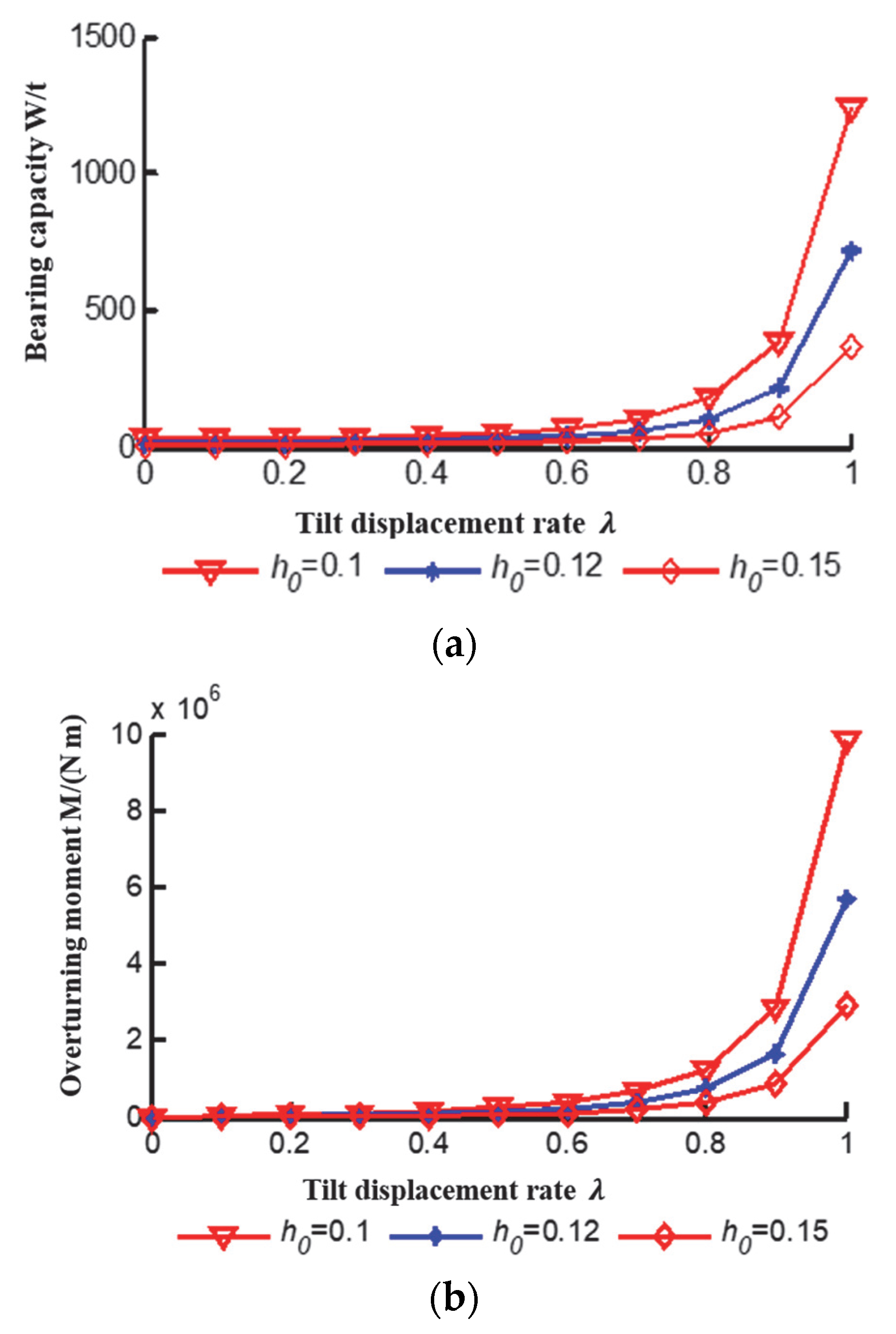
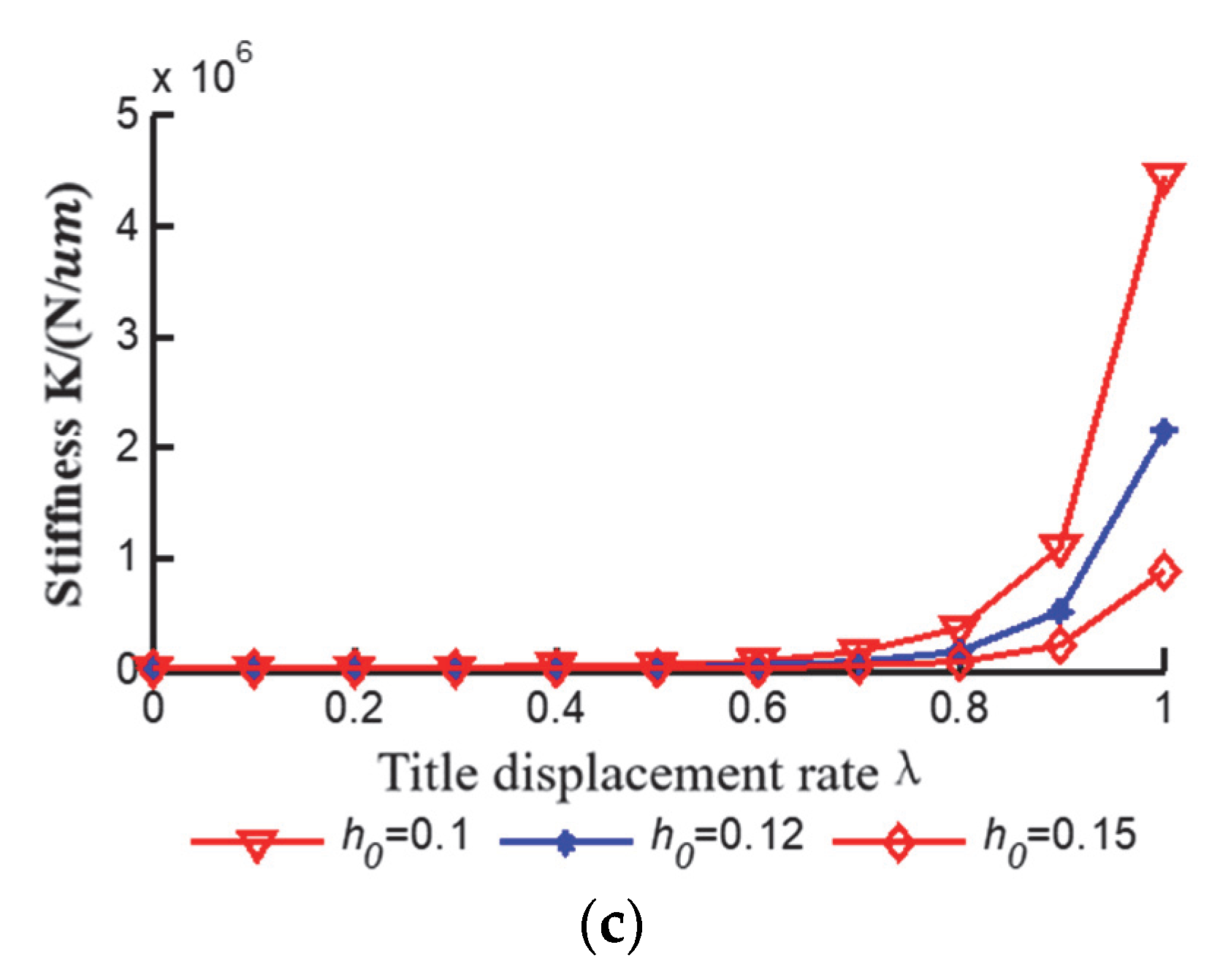
5.2. Effects of Tilt Displacement Rate on Bearing Capacity, Overturning Moment and Stiffness of Oil Film

When the hydrostatic turntable is subjected to a constant bias load, the oil chamber pressure and load capacity of each oil pad change with the tilt of the oil film, which in turn generates the overturning moment. The inclined displacement rate of the lubricant film has a significant effect on the load-bearing characteristics of a constant bias-loaded hydrostatic turntable.
When the lubricant temperature is 30 °C, the oil flow rate is 6 L/min, and the rotation speed is 0 r/min; the relationship between the oil film bearing capacity, overturning moment, stiffness and oil film inclined displacement rate of the constant bias load hydrostatic turntable is shown in Figure 11.
As shown in Figure 10, oil film load capacity, overturning moment and stiffness increase with the increase in the tilt displacement rate of the turntable. The larger the tilt displacement rate, the more significant the effect.
In the oil film thickness of 0.15 mm working condition, when the tilt displacement rate is 0, the oil film bearing capacity is 8.03 t, the overturning moment is 0, and the oil film stiffness is 3.39 × 10 3 N / μ m . When the tilt displacement rate is 0.2, 0.4, 0.6, 0.8 and 1, the oil film bearing capacity is 8.81 t, 11.8 t, 20.35 t, 52.65 t and 366.3 t, and the overturning moment is 1.93 × 10 4 N m , 4.93 × 10 4 N m , 1.19 × 10 5 N m , 3.74 × 10 5 N m and 2.91 × 10 6 N m . The oil film stiffness is 4 × 10 3 N / μ m , 6.67 × 10 3 N / μ m , 1.66 × 10 4 N / μ m , 7.37 × 10 4 N / μ m and 8.78 × 10 5 N / μ m , respectively.

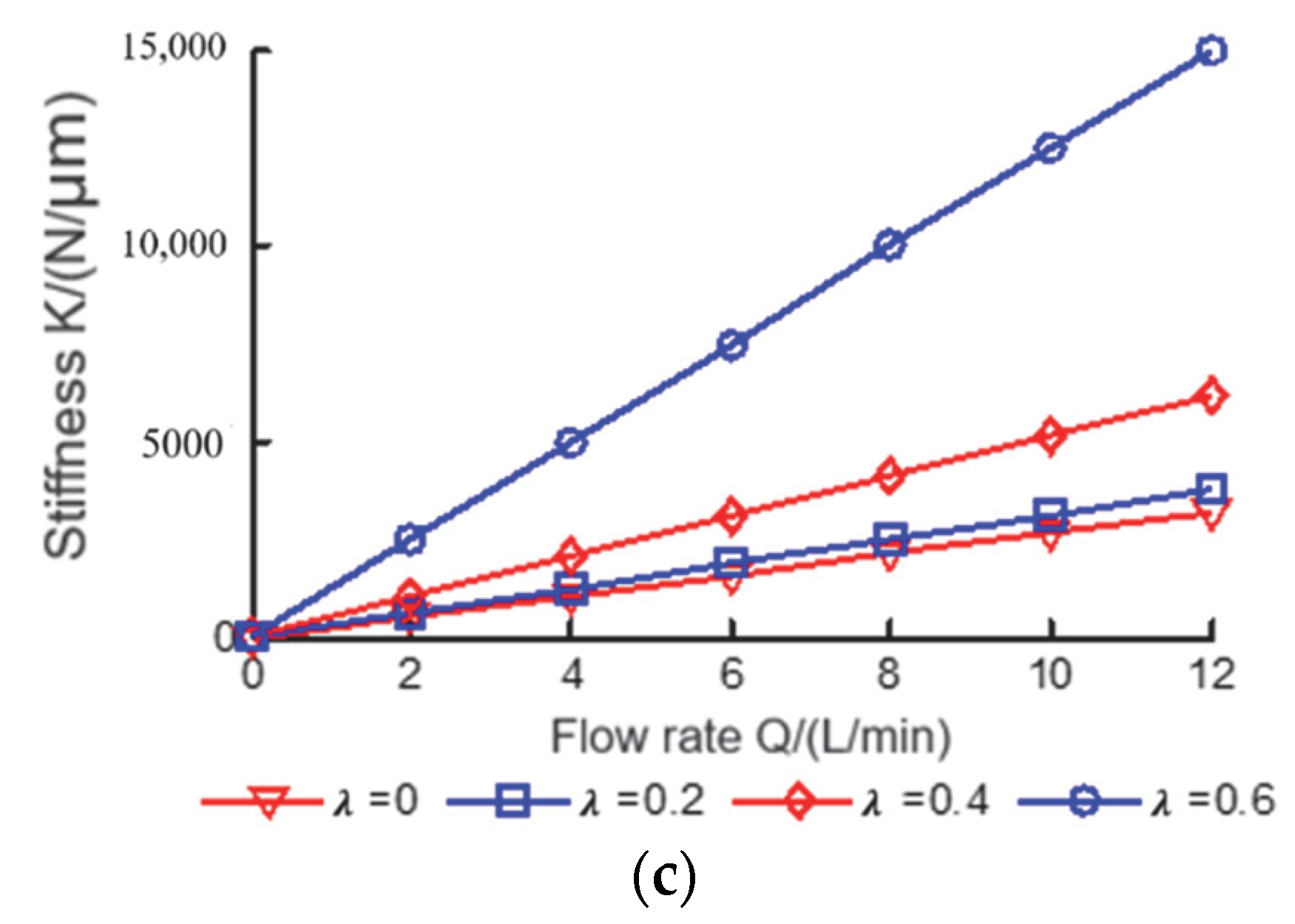
5.3. Effects of Lubricant Flow on Bearing Capacity, Overturning Moment and Stiffness of Oil Film

For the hydrostatic turntable subjected to a constant bias load, when the thickness of the oil film center and the tilt displacement rate are constant, the lubricant flow rate plays a key role in influencing the bearing capacity, overturning moment and stiffness.
When the lubricant temperature is 30 °C, the table center clearance is 0.15 mm, and the rotation speed is 0 r/min; the relationship between oil film bearing capacity, overturning moment, stiffness and lubricant flow rate of the constant bias load liquid hydrostatic turntable is shown in Figure 12.
As shown in Figure 12, the oil film bearing capacity, overturning moment and stiffness of the hydrostatic turntable are linearly related to the flow rate of lubricating oil and increase with the increase in flow rate. The reason is: the mathematical model of a constant bias load hydrostatic turntable oil film bearing capacity, overturning moment and stiffness are proportional to the lubricant flow. The greater the tilt displacement rate, the more significant the effect of lubricant flow on the hydrostatic turntable load bearing capacity, overturning moment and stiffness.
The linear factor of oil film bearing capacity and lubricant flow rate for tilt displacement rate of 0, 0.2, 0.4 and 0.6 are 1.34, 1.47, 1.97 and 3.39, respectively; the linear factor of overturning moment and lubricant flow were 0 , 3.21 × 10 3 , 8.22 × 10 3 , 1.98 × 10 4 ; the linear factor of oil film stiffness and lubricant flow were 267.67, 314.5, 515.33, 1249.17.

5.4. Effects of the Rotation Speed on Bearing Capacity, Overturning Moment and Stiffness of Oil Film

For hydrostatic turntable subjected to a constant bias load, when the thickness of the oil film center, the tilt displacement rate and the lubricant flow rate are constant, the rotation speed plays a decisive role in influencing bearing capacity and overturning moment.
When the lubricant temperature is 30 °C, the table center clearance is 0.15 mm, and the oil flow rate is 6 L/min; the relationship between oil film bearing capacity, overturning moment, stiffness and the rotation speed of the constant bias load liquid hydrostatic turntable is shown in Figure 13.
As shown in Figure 13a, the hydrostatic turntable oil film load capacity decreases as the speed increases.
The reason is: centrifugal force reduces the oil film bearing capacity. The higher the speed, the more obvious the effect of centrifugal force on the oil film bearing capacity. The oil film load capacity is 12.04 t at a tilt displacement rate of 0.4 and a rotational speed of 0 r/min, the load capacity is 12 t, 11.87 t, 11.66 t, 11.37 t and 10.99 t at 200 r/min, 400 r/min, 600 r/min, 800 r/min and 1000 r/min, respectively. The reductions were 0.3%, 0.6%, 3.2%, 5.6% and 9%, respectively.
As shown in Figure 13b, the oil film tilting torque increases as the speed increases. The reason is: the dynamic pressure effect caused by the rotational speed has an effect on the oil film overturning moment. The higher the speed, the greater the effect of dynamic pressure on the oil film overturning moment. When the tilt displacement rate is 0, the hydrostatic turntable is kept horizontal, no deflection load is applied, and the overturning moment is 0 N·m. The oil film overturning moment is 5.76 × 10 4   N m at a tilt displacement rate of 0.4 and a rotation speed of 0 r/min. The overturning moment is 5.77 × 10 4   [ Nm ]   , 5.81 × 10 4   [ Nm ]   , 5.88 × 10 4   [ Nm ]   , 5.97 × 10 4   [ Nm ]   and 6.09 × 10 4   [ Nm ]   at 200 r/min, 400 r/min, 600 r/min, 800 r/min and 1000 r/min, which increased by 0.1%, 0.9%, 2.1%, 3.6% and 5.7%, respectively.
As shown in Figure 12c, the fluid hydrostatic turntable oil film stiffness is independent of speed. At tilt displacement rates of 0, 0.2, 0.4 and 0.6, the oil film stiffness was 1.61 × 10 3   N / μ m , 1.89 × 10 3   N / μ m , 3.09 × 10 3   N / μ m and 7.50 × 10 3   N / μ m .

6. Conclusions

(1) In this paper, in order to solve the deficiencies of the existing calculation methods of the load-bearing characteristics of the hydrostatic turntable with constant bias load, the uneven thickness of the oil film of each sealing edge of the oil pad is simplified to be equivalent to the uniform thickness of the oil film, and based on this idea, the calculation method of the oil film load-bearing characteristics of the hydrostatic turntable with constant bias load is simplified. The calculation results obtained by this method are in basic agreement with the CFD simulation calculation results and experimental data, which confirms the validity of the calculation method.
(2) The load-bearing characteristics of the constant bias hydrostatic turntable are mainly influenced by the operating parameters such as tilt displacement rate and lubricant flow rate. The study shows that: (a) with the increase in the tilt displacement rate of the hydrostatic turntable, the side where the tilt occurs, the oil film thickness decreases and the pressure in the oil chamber increases. Conversely, on the opposite side, the thickness of the oil film increases and the pressure in the oil chamber decreases. (b) Oil film load capacity, overturning moment and stiffness increase with the increase in the tilt displacement rate of the hydrostatic turntable. The larger the tilt displacement rate is, the more significant the effect is. (c) The hydrostatic rotary table oil film bearing capacity, overturning moment and stiffness are linearly related to the flow of lubricant and increase with the flow of lubricant. (d) As the speed of the hydrostatic rotary table increases, the oil film bearing capacity decreases and the overturning moment increases.

Author Contributions

S.W.: review and editing, validation, and supervision; J.L. and Y.Z.: data curation, investigation and writing-original draft; K.G. and C.Z.: methodology, data curation., revision. All authors have read and agreed to the published version of the manuscript.

Funding

The Outstanding Youth Fund Project of Hunan Provincial Department of Education (19B127).

Institutional Review Board Statement

Not applicable.

Informed Consent Statement

Not applicable.

Data Availability Statement

All data used to support the findings of this study are included within the article.

Acknowledgments

The authors would like to acknowledge the Outstanding Youth Fund Project of Hunan Provincial Department of Education (19B127).

Conflicts of Interest

The authors declare that there is no conflict of interest regarding the publication of this paper.

References

  1. Ma, L.; Zhang, W.; Zhao, X.; Zhao, J.; Wang, T. Oil film characteristics and flow field analysis of asymmetrical hydrostatic support structure with full hydraulic fixed-length shear servo cylinder. Eng. Fail. Anal. 2021, 120, 105101. [Google Scholar] [CrossRef]
  2. Wang, Y.; Zhao, Y.; Cai, L.; Liu, Z.; Cheng, Q. Effects of thermal and hydrodynamic characteristics of heavy-duty rotary table on the hydrostatic circular pads. J. Vibroeng. 2016, 18, 4193–4206. [Google Scholar] [CrossRef] [Green Version]
  3. Kozdera, M.; Drábková, S. Numerical modeling of the flow in the annular multi-recess hydrostatic thrust bearing using CFD methods. EPJ Web Conf. 2013, 45, 01051. [Google Scholar] [CrossRef]
  4. Rehman, W.U.; Wang, X.; Chen, Y.; Yang, X.; Ullah, Z.; Cheng, Y.; Kanwal, M. An active control for hydrostatic journal bearing using optimization algorithms. Ind. Lubr. Tribol. 2021, 73, 316–324. [Google Scholar] [CrossRef]
  5. Alves, D.S.; Machado, T.H.; Cavalca, K.L.; Bachschmidb, N. Characteristics of oil film nonlinearity in bearings and its effects in rotor balancing. J. Sound Vib. 2019, 459, 114854. [Google Scholar] [CrossRef]
  6. Liu, C.; Hu, J. A FSI-thermal model to analyze performance characteristics of hydrostatic turntable. Ind. Lubr. Tribol. 2018, 70, 1692–1698. [Google Scholar] [CrossRef]
  7. Andrés, L.S.; Rohmer, M.; Wilkinson, S. Static Load Performance of a Water-Lubricated Hydrostatic Thrust Bearing. J. Eng. Gas Turbines Power 2017, 140, 062401. [Google Scholar]
  8. Liu, Z.; Zhan, C.; Cheng, Q.; Zhao, Y.S.; Li, X.Y.; Wang, Y.D. Thermal and tilt effects on bearing characteristics of hydrostatic oil pad in rotary table. J. Hydrodyn. 2016, 28, 585–595. [Google Scholar] [CrossRef]
  9. Dong, X.; Cai, L.; Liu, Z.; Zhao, Y.; Wang, Y. Research of Oil Film Characteristics of Hydrostatic Turntable under Rotation and Tilt. Int. J. Simul. Syst. Sci. Technol. 2016, 17, 8.1–8.9. [Google Scholar]
  10. Li, M.; Li, X.; Zhang, X.; Fan, R.; Cai, Y. An Investigation into the Mechanical Properties of Hydro-static Thrust Bearing for Constant Flow Circular Ring Oil Pad. Int. J. Simul. Syst. Sci. Technol. 2016, 17, 231–237. [Google Scholar]
  11. Gao, Q.; Qi, L.; Gao, S.; Lu, L.; Song, L.; Zhang, F. A FEM based modeling method for analyzing the static performance of aerostatic thrust bearings considering the fluid-structure interaction. Tribol. Int. 2021, 156, 106849. [Google Scholar] [CrossRef]
  12. Yu, X.; Geng, L.; Zheng, X.; Wang, Z.X.; Wu, X.G. Matching the relationship between rotational speed and load-carrying capacity on high-speed and heavy-load hydrostatic thrust bearing. Ind. Lubr. Tribol. 2018, 70, 8–14. [Google Scholar] [CrossRef]
  13. Liu, Z.; Wang, Y.; Cai, L.; Zhao, Y.; Cheng, Q.; Dong, X. A review of hydrostatic bearing system: Researches and applications. Adv. Mech. Eng. 2017, 9, 1687814017730536. [Google Scholar] [CrossRef]
  14. Liang, P.; Lu, C.; Pan, W.; Li, S. A new method for calculating the static performance of hydrostatic journal bearing. Tribol. Int. 2014, 77, 72–77. [Google Scholar] [CrossRef]
  15. Hsiao, S.T.; Kang, Y.; Jong, S.M.; Lee, H.H.; Peng, D.X.; Chang, Y.P. Static analysis of hydrostatic conical bearings using flow resistance network method. Ind. Lubr. Tribol. 2014, 66, 411–423. [Google Scholar] [CrossRef]
  16. Wu, L.; Song, B.; Zhou, Y.; Hao, M. Analysis on Oil Film of Hydrostatic Bearing in Gear Pump Operating at High Pressures and High Speeds. Int. J. Simul. Syst. Sci. Technol. 2016, 17, 25.1–25.4. [Google Scholar]
  17. Bouyer, J.; Wodtke, M.; Fillon, M. Experimental research on a hydrodynamic thrust bearing with hydrostatic lift pockets: Influence of lubrication modes on bearing performance. Tribol. Int. 2022, 165, 107253. [Google Scholar] [CrossRef]
  18. Gao, S.; Shang, Y.; Gao, Q.; Lu, L.; Zhu, M.; Sun, Y.; Yu, W. CFD-based investigation on effects of orifice length–diameter ratio for the design of hydrostatic thrust bearings. Appl. Sci. 2021, 11, 959. [Google Scholar] [CrossRef]
  19. Yu, X.; Wu, G.; Zhou, W.; Bi, H.; Wang, Y.; Gao, W.; Wang, J.; Jiao, J.; Jiang, H. Inclination angle effect of tribological performance for hydrostatic bearing having tilting oil pad under variable viscosity conditions. J. Braz. Soc. Mech. Sci. Eng. 2021, 43, 231. [Google Scholar] [CrossRef]
  20. Tian, Z.; Cao, H.; Huang, Y. Static characteristics of hydrostatic thrust bearing considering the inertia effect on the region of supply hole. Proc. Inst. Mech. Eng. Part J J. Eng. Tribol. 2019, 233, 188–193. [Google Scholar] [CrossRef]
  21. Zhang, Y.; Kong, P.; Feng, Y.; Guo, L. Hot oil carrying characteristic about hydrostatic bearing oil film of heavy vertical lathe in high speed. Ind. Lubr. Tribol. 2019, 71, 126–132. [Google Scholar] [CrossRef]
  22. Zhang, Y.; Qu, Y.; Shen, Z.; Wu, W.Q.; Wu, F.B.; Xu, L.Y. Oil Film Carrying Property Research of Hydrostatic Vertical Guideway of CNC Vertical Lathe. In Key Engineering Materials; Trans Tech Publications Ltd.: Wollerau, Switzerland, 2014; Volume 579–580, pp. 564–567. [Google Scholar]
  23. Zhang, Y.; Fan, L.; Li, R.; Dai, C.X.; Yu, X.D. Simulation and experimental analysis of supporting characteristics of multiple oil pad hydrostatic bearing disk. J. Hydrodyn. 2013, 25, 236–241. [Google Scholar] [CrossRef]
  24. Xiong, W.; Fu, M.; Wang, S.; Lü, L. Analyses on tilted oil film dynamical characteristics of hydrostatic rotary tables. China Mech. Eng. 2014, 25, 3326. [Google Scholar]
  25. Zhao, J.; Liang, Y.; Gao, D. Oil pocket’s bearing capacity analysis of liquid hydrostatic worktable in gantry moving milling center. Chin. J. Mech. Eng. 2014, 27, 1008–1017. [Google Scholar] [CrossRef]
  26. Rehman, W.U.; Wang, X.; Cheng, Y.; Chen, Y.; Shahzad, H.; Chai, H.; Abbas, K.; Ullah, Z.; Kanwal, M. Model-Based Design Approach to Improve Performance Characteristics of Hydrostatic Bearing Using Multivariable Optimization. Mathematics 2021, 9, 388. [Google Scholar] [CrossRef]
  27. Zhang, Y.; Hou, J.; Gao, W.; Zhao, Z.; Zhou, D.; Cheng, H. Prediction model of the clearance oil film for static vertical rail considering the ram deformation. Proc. Inst. Mech. Eng. Part J J. Eng. Tribol. 2020, 234, 42–49. [Google Scholar] [CrossRef]
  28. Xiong, W.; Hu, C.; Lv, L.; Zheng, L.G. Research on the influence of controllable restrictor parameters on the characteristics of hydrostatic journal bearing. Chin. J. Mech. Eng. 2018, 54, 63–71. [Google Scholar] [CrossRef]
  29. Li, X.; Wang, X.; Li, M.; Ma, Y.; Huang, Y. The research status and progress of heavy/large hydrostatic thrust bearing. Adv. Mech. Eng. 2014, 6, 982584. [Google Scholar] [CrossRef]
  30. Cheng, Y. Liquid Hydrostatic Support Principle and Design; National Defense Industry Press: Arlington, VA, USA, 1980. [Google Scholar]
  31. Zhang, Y.; Liu, G.; Yang, X.; Hu, C.; Wang, H.; Shao, J. Coupled solving thermal deformation of hydrostatic bearing rotary worktable based on temperature fields of oil film. J. Comput. Theor. Nanosci. 2015, 12, 3917–3921. [Google Scholar] [CrossRef]
  32. Zhang, Y.; Zhang, Z.; Kong, X.; Li, R.; Jiang, H. Application of dynamic mesh technology in the oil film flow simulation for hydrostatic bearing. Ind. Lubr. Tribol. 2018, 71, 146–153. [Google Scholar] [CrossRef]
Figure 1. Schematic diagram of the hydrostatic turntable subjected to bias load.
Processes 10 02017 g001
Figure 2. Schematic diagram of load and overturning moment of turntable under partial load. (a) Guide rail and parameter schematic; (b) Overall physical picture of the turntable; (c) Guides and their internal structure. 1—Oil chamber; 2—Turntable; 3—Guide.
Processes 10 02017 g002aProcesses 10 02017 g002b
Figure 3. Schematic diagram of a single fan-shaped flat oil pad.
Processes 10 02017 g003
Figure 4. Oil film fluid domain mesh. (a) Fluid domain mesh, (b) Local magnification diagram.
Processes 10 02017 g004
Figure 5. Cloud diagram of pressure distribution of biased oil film.
Processes 10 02017 g005
Figure 6. Heavy duty hydrostatic turntable test system.
Processes 10 02017 g006
Figure 7. Heavy duty hydrostatic turntable test system working principal diagram.
Processes 10 02017 g007
Figure 8. Relationship between load bearing force and tilt displacement rate.
Processes 10 02017 g008
Figure 9. Relationship between overturning moment and tilt displacement rate.
Processes 10 02017 g009
Figure 10. Influence of tilt displacement rate on pressure of oil pad cavity and average thickness of the outer circular sealing edge of oil pad. (a) Effect on the average oil film thickness of the outer arc sealing edge of each oil pad; (b) Effect on the pressure in each oil chamber; (c) Local magnification of effect on the pressure of each oil chamber of the oil pad.
Processes 10 02017 g010
Figure 11. Influence of inclined displacement rate on bearing characteristics. (a) Influence on oil film bearing capacity; (b) Influence on oil film overturning moment; (c) Influence of inclined displacement rate on oil film stiffness.
Processes 10 02017 g011aProcesses 10 02017 g011b
Figure 12. Influence of flow rate on bearing characteristics. (a) Influence on oil film bearing capacity; (b) Influence on oil film overturning moment; (c) Influence of inclined displacement rate on oil film stiffness.
Processes 10 02017 g012aProcesses 10 02017 g012b
Figure 13. Influence of rotational speed on bearing characteristics. (a) Influence on oil film bearing capacity; (b) Influence on oil film overturning moment; (c) Influence of inclined displacement rate on oil film stiffness.
Processes 10 02017 g013aProcesses 10 02017 g013b
Publisher’s Note: MDPI stays neutral with regard to jurisdictional claims in published maps and institutional affiliations.

