Article

Glucose Biosensor Based on Dendritic Gold Nanostructures Electrodeposited on Graphite Electrode by Different Electrochemical Methods

by
Almira Ramanaviciene
1,2,*,
Natalija German
2,
Asta Kausaite-Minkstimiene
1,2 and
Arunas Ramanavicius
3
1
NanoTechnas—Center of Nanotechnology and Materials Science, Faculty of Chemistry and Geosciences, Vilnius University, LT-03225 Vilnius, Lithuania
2
Department of Immunology, State Research Institute Centre for Innovative Medicine, Santariskiu 5, LT-08406 Vilnius, Lithuania
3
Department of Physical Chemistry, Faculty of Chemistry and Geosciences, Vilnius University, Naugarduko 24, LT-03225 Vilnius, Lithuania
*
Author to whom correspondence should be addressed.
Chemosensors 2021, 9(8), 188; https://doi.org/10.3390/chemosensors9080188
Submission received: 22 June 2021 / Revised: 13 July 2021 / Accepted: 19 July 2021 / Published: 22 July 2021

Abstract

:
In this research, we have demonstrated a one-step electrochemical deposition of dendritic gold nanostructures (DGNs) on a graphite rod (GR) electrode without any template, seeds, surfactants, or stabilizers. Three electrochemical methods, namely, constant potential amperometry (CPA), pulse amperometry, and differential pulse voltammetry, were used for DGN synthesis on GR electrode and further application in enzymatic glucose biosensors. Formed gold nanostructures, including DGNs, were characterized by a field emission scanning electron microscopy. The optimal concentration of HAuCl4 (6.0 mmol L−1), duration of DGNs synthesis (400 s), electrodeposition potential (−0.4 V), and the best electrochemical method (CPA) were determined experimentally. Then the enzyme, glucose oxidase, was adsorbed on the surface of DGNs and covalently cross-linked with glutaraldehyde vapor. The enzymatic glucose biosensor based on DGNs electrodeposited at optimal conditions and modified with glucose oxidase showed a quick response (less than 3 s), a high saturation current (291 μA), appropriate linear range (up to 9.97 mmol L−1 of glucose, R2 = 0.9994), good repeatability (RSD 2.4, 2.2 and 1.5% for 2, 30, 97 mmol L−1 of glucose), low limit of detection (0.059 mmol L−1, S/N = 3) and good stability. Additionally, this biosensor could be successfully applied for glucose determination in real samples with good accuracy. These results proved the principle of enzymatic glucose biosensor development based on DGNs as the basis for further investigations.

1. Introduction

Nowadays, gold micro- and nano-structures of various forms have received considerable attention due to their size- and shape-dependent physical and chemical properties [1,2,3]. The stars, three-dimensional meso-flowers, porous textile-like gold sheets, raspberry- and urchin-like gold nanostructures have attracted increased interest due to their enhanced electrocatalytic activity, efficiency and high sensitivity in surface-enhanced Raman spectroscopy (SERS) [4,5,6]. Recently, dendritic gold nanostructures (DGNs) have received great success among various shaped nanostructures due to (i) their importance in the understanding of their growth mechanism and regulation of this process [7], (ii) their superhydrophobic properties [8], (iii) high surface-to-volume ratio [9], and unique size- and shape-dependent properties, such as (iv) enhanced SERS sensitivity [10,11], (v) photoluminescence emission [12], and (vi) electrocatalytic activity [13]. The shape-controlled synthesis of DGNs can be achieved using different methods, such as the wet chemical method [11,14], galvanic replacement [15], seeded growth and template methods [16,17], hydrothermal reduction [18], interface-mediated synthesis [19], and electrochemical deposition [7,13]. The direct, cost-effective, rapid electrochemical deposition and growth of DGNs from the aqueous solution of HAuCl4 via potentiostatic methods could be performed on a polycrystalline gold surface at a potential of 0.0 mV (vs. Ag/AgCl/KCl 3 mol L−1) for 600 s [20], on a glassy carbon (GC) electrode at a potential of −0.3 mV (vs. Ag/AgCl) for 3600 s [21], or by a square-wave voltammetry technique using lower and higher potentials of −0.8 V and +0.2 V (vs. Ag/AgCl/NaCl 3 mol L−1) at a frequency of 40 Hz for 2000 s [22], on GC electrode premodified with reduced graphene oxide functionalized by β-lactoglobulin at −0.4 V (vs. Ag/AgCl/KClsat.) for 120 s [23], on fluorine-doped tin oxide (FTO)-coated glass at −0.25 V (vs. Ag/AgCl) for 300 s [24], on GC electrode premodified with multiwalled carbon nanotubes and gold nanoparticle hybrid (MWCNT-AuNPs) structure using chronoamperometry at a constant −0.30 V potential (vs. Ag/AgCl) for 1500 s [25], or a paper fiber-based electrode at −0.08 or −0.20 V (vs. Ag/AgCl) for 4 min [26]. It is known that the selected potential has impact on the morphology and size of electrodeposited gold nanostructures [27].
Usually the potential controlled electrochemical deposition of anisotropic DGNs on different supports can be achieved using various organic and inorganic additives or surfactants. Histidine as a soft template [20], ethylenediamine, cytosine, 3-aminopropyltriethoxysilane as the agents for initial branching and for subsequent growth and/or structure directing [24,28,29], cysteine as the Au(100) and (110) blocking molecule and inducing the preferential growth of DGNs along the Au(111) directions [7], nicotinamide adenine dinucleotide as the growth of DGNs along the Au(111) directions enhancing agent [22], and L-asparagine [30] as the agent regulating the shape and morphology of the DGNs and β-lactoglobulin as the stabilizer [23] were used for this purpose. Additionally, small iodide ions were used as an agent preventing the continual growth of gold into larger agglomerates and inhibiting the coalescence of the neighbouring nanodendrites [31]. The ion of SO42− formed in the presence of Na2SO4 in the synthesis solution preferred to adsorb on Au(111) planes and so block their growth [32].
Mainly gold or glassy carbon electrodes electrochemically premodified with DGNs or coated by casting the already synthetized DGN suspension were applied for superior electrocatalytic oxidation of ethanol (in comparison to the polycrystalline Au nanoparticles) [28], methanol (in comparison to the Au nanostructures) [11,22], and sensitive and selective determination of bisphenol A with a strong anti-interference ability [30]. DGNs electrodeposited on the electrode and additionally decorated by Pt clusters were applied for the electrocatalytic oxidation of formic acid. Due to more defect sites and edges, DGNs with Pt clusters demonstrated different electrochemical behaviors (lower oxidation peak potential and higher oxidation peak current density) in comparison to the same Pt clusters on smooth gold or gold nanoparticles (AuNPs) [33]. On the GC electrode formed an MWCNT-AuNPs/DGNs nanohybrid with enhanced catalytic activity that was used for acetaminophen detection in human urine [25]. Additionally, DGNs were used for the nonenzymatic detection of glucose in neutral and alkaline pH solutions [13,20,21,22,24,26]. An enhanced electrocatalytic oxidation of glucose at lower potentials than for some other gold-based electrodes (+0.38 V vs. Ag/AgCl/NaCl 3 mol L−1) [22], a low limit of detection (LOD) (0.05 mmol L−1 [21], 0.005 mmol L−1 [24]), high stability for a longer period of time, lower coast, good sensitivity to glucose (37.29 μA cm−2 mM−1 [24], 190.7 μA cm−2 mM−1 [21]), wide linear range (0.1–25 mmol L−1), good repeatability, quick response (less than 2 s), possibility to detect glucose in a wide pH interval [21] were experimentally determined. Polypyrrole functionalized DGNs were successfully applied for the immobilization of antibodies and for the development of a sensitive immunosensor for cholera detection [34]. Despite the listed advantages of the nonenzymatic electrocatalytic oxidation of glucose, the activity of electrodes premodified with gold can easily be lost or be affected by adsorbed intermediates, especially at neutral pH [35].
Enzymatic glucose biosensors based on glucose oxidase (GOx) immobilized on AuNPs distinguished from nonenzymatic sensors by such advantages as increased selectivity and sensitivity to glucose, a better stability of biosensors based on hierarchical Au-Ni alloy with a conductive polymer in comparison to the nonenzymatic sensors [36], physiologically relevant linear range, and the ability to detect glucose in the blood (in the presence of other electrochemically active substances) at a physiological pH [37]. Additionally, AuNPs are biocompatible and can ensure higher GOx uploading on the same electrode surface using different immobilisation methods (adsorption, chemisorption, covalent immobilisation via self-assembled monolayers), proper orientation of enzyme molecules, higher enzymatic activity and stability, and improved charge transfer [38,39,40].
Nowadays, the development of quick, sensitive, selective, reliable, accurate, and user-friendly glucose detection systems for people with diabetes are of high importance. The modification of the electrode with DGNs presents many benefits not only for nonenzymatic glucose detection. DGNs, due to an increased electrode working surface area, enhanced electron transfers as well as improved orientation and more uniform distribution of enzyme molecules on the surface, improve the performance of the enzymatic glucose biosensor. The aim of this work was to synthesize dendritic gold nanostructures on the graphite rod electrode surface (DGNs/GR) in one step, without any template, seeds, surfactant and stabilizer (they complicate and prolong the synthetic procedure, may block the active sites and introduce heterogeneous impurities) using different electrochemical methods to select the best of them for the development of a sensitive and convenient amperometric enzymatic glucose biosensor. Additionally, the optimal conditions for the development of a glucose biosensor based on a DGNs/GR electrode were selected experimentally. The presented electrochemical method for the deposition of DGNs is a powerful, fast, cost-effective, and green method. The application of DGNs for the development of an enzymatic second generation glucose biosensor was shown in this work, while the use of DGNs for the nonenzymatic determination of glucose and other analytes has already been published in many articles.

2. Materials and Methods

2.1. Materials

Glucose oxidase (EC 1.1.3.4, type VII, from Aspergillus niger, 208 units mg−1 protein) was received from Sigma-Aldrich (Buchs, Switzerland). Phenazine methosulfate (PMS), 25% glutaraldehyde solution, L-ascorbic and uric acids were obtained from AppliChem GmbH (Darmstadt, Germany). Hydrogen tetrachloroaurate(III) trihydrate (HAuCl4 × 3 H2O), D-(+)-glucose, D(+)-saccharose, D(+)-xylose, D(+)-galactose, D(+)-mannose, and D(−)-fructose were acquired from Carl Roth GmbH + Co. KG (Karlsruhe, Germany), hydrochloric acid 37%—from Acta Medica (Hradec Kralove, Czech Republic) and potassium nitrate—from Acros Organics (New Jersey, NJ, USA). Before investigation, the glucose solution was allowed to stay overnight for the equilibrium of the α-β optical isomers. All chemicals used in the present study were either analytical grade or better. All solutions were prepared using deionized water purified with the water purification system Millipore S.A. (Molsheim, France). The sodium acetate (SA) buffered solution (0.05 mol L−1 CH3COONa) with 0.1 mol L−1 KCl was prepared by mixing CH3COONa × 3H2O and KCl, which were obtained from Reanal (Budapest, Hungary) and Lachema (Neratovice, Czech Republic), respectively. Graphite rods (3 mm diameter, 99.999%, low density) were purchased from Sigma-Aldrich (St. Louis, MO, USA), alpha alumina powder (grain diameter 0.3 μm, Type N)—from Electron Microscopy Sciences (Hatfield, MA, USA).

2.2. Pretreatment of the Working Electrode and Optimization of Electrochemical DGN Synthesis

GR was cut and polished on fine emery paper and later on slurry alpha alumina powder. After this, the surface of the GR electrode was rinsed with distilled water, dried at 20 ± 2 °C and sealed in a silicone tube to prevent contact of the electrode’s side surface with the solution. The active GR electrode surface area was 0.071 cm2. The concentration of HAuCl4, potential applied to the working electrode, duration and preferred electrochemical methods of DGNs electrochemical deposition were optimized to achieve the maximal sensitivity of glucose biosensor. For the modification of GR with DGNs the electrode was placed in the solution of appropriate concentration of HAuCl4 with 0.1 mol L−1 KNO3 and the selected electrochemical method was applied using a computerized potentiostat PGSTAT 30/Autolab (EcoChemie, Utrecht, Netherlands) with GPES 4.9 software. The electrochemical deposition of DGNs for 200 s at constant −0.2 V potential vs. Ag/AgCl/KCl 3 mol L−1 was performed using 0.02, 3.0 and 6.0 mmol L−1 solution of HAuCl4 with 0.1 mol L−1 KNO3 for the evaluation of the optimal concentration of HAuCl4. The selection of the optimal DGN deposition potential was performed in the solution of 6 mmol L−1 HAuCl4 with 0.1 mol L−1 KNO3 for 400 s changing the constant potential of the working electrode from −1.0 to +0.4 V. The optimal time required for the potential controlled electrochemical deposition of DGNs was determined changing the duration of electrochemical deposition from 50 to 1200 s in the solution of 6 mmol L−1 HAuCl4 with 0.1 mol L−1 KNO3 at constant potential −0.4 V vs. Ag/AgCl/KCl 3 mol L−1. For selection of the best electrochemical method for the modification of GR electrode, electrochemical deposition of DGNs was performed in a solution of 6 mmol L−1 HAuCl4 with 0.1 mol L−1 of KNO3 (i) at constant −0.4 V potential vs. Ag/AgCl/KCl 3 mol L−1 for 400 s (constant potential amperometry, CPA), (ii) changing potential by pulses (pulse amperometry, PA): −0.4 V for 100 s and 0 V for 1 s, repeating these pulses 4 times, and (iii) sweeping potential from −0.4 to 0 V vs. Ag/AgCl/KCl 3 mol L−1 during 400 s, scan rate 0.001 V s−1, step potential 0.0003 V, pulse amplitude 0.025 V (differential pulse voltammetry, DPV).

2.3. Imaging of DGN/GR Electrode by Field Emission Scanning Electron Microscopy

The surface of GR electrodes modified by electrochemically deposited DGNs was characterized by a high resolution field emission scanning electron microscope SU-70 (Hitachi, Tokyo, Japan) (FE-SEM).

2.4. Immobilization of GOx on GR Electrode Premodified with Electrochemically Deposited DGNs

A portion of 3 µL of 25 mg mL−1 GOx solution was deposited on the DGNs premodified GR electrode surface (GOx/DGNs/GR). After the evaporation of water, the working electrode was stored for 15 min in a closed vessel over a 25% solution of glutaraldehyde at room temperature (+20 ± 2 °C). Before all electrochemical measurements, GOx modified electrodes were washed with distilled water to remove non-cross-linked enzymes. All working electrodes were stored in a closed vessel over SA buffer (pH 6.0) at +4 °C before use. Prior to electrochemical measurements, the electrodes were washed with distilled water.

2.5. Electrochemical Measurements

All electrochemical measurements during the registration of glucose were performed with a computerized potentiostat PGSTAT 30/Autolab with GPES 4.9 software using the three-electrodes system: premodified working GR electrode, 2 cm2 platinum wire as an auxiliary electrode and a reference Ag/AgCl/KCl 3 mol L−1 electrode (Metrhom, Herisau, Switzerland) (Scheme 1). Amperometric signals were evaluated in 0.05 mol L−1 SA buffer with 0.1 mol L−1 KCl (pH 6.0) and 2.0 mmol L−1 PMS after enzyme immobilization on GR surface premodified with DGNs at different conditions. Firstly, a steady current was reached (stable baseline), and then different concentrations of glucose were added. The reoxidation currents of PMSH2 (reduced form of PMS) at +0.3 V potential vs. Ag/AgCl/KCl 3 mol L−1 were registered at glucose concentrations ranging from 0.1 to 97 mmol L−1. The current response under certain concentrations of glucose (ΔI) was evaluated as the difference of registered steady anodic currents after the addition of glucose and baseline. All investigations were performed at +20 ± 2 °C temperature in a 5 mL volume electrochemical cell stirring solution with a magnetic stirrer (1200 rpm).

2.6. Calculations

Amperometric signal showed hyperbolic dependence on glucose concentration and it was in agreement with Michaelis−Menten kinetics. The saturation current (ΔImax) generated during the enzymatic reaction was a parameter of the hyperbolic function y = ax/(b + x), which was used for the approximation of results. ΔImax of the enzyme catalysed reaction were calculated using SigmaPlot software (version 11.00). The results of all electrochemical measurements are reported as the mean value of minimum three independent experiments. Calibration curve parameters, such as slope and determination coefficient (R2), were evaluated. The limit of detection as the lowest concentration of analyte, which gives an analytical signal greater than the background value plus 3 σ, was also estimated using the statistic software SigmaPlot 11. At least three samples were used for the calculation of the signal-to-noise ratio.

3. Results and Discussion

3.1. The Optimization of Electrochemical Deposition of DGNs

3.1.1. The Selection of Optimal HAuCl4 Solution Concentration

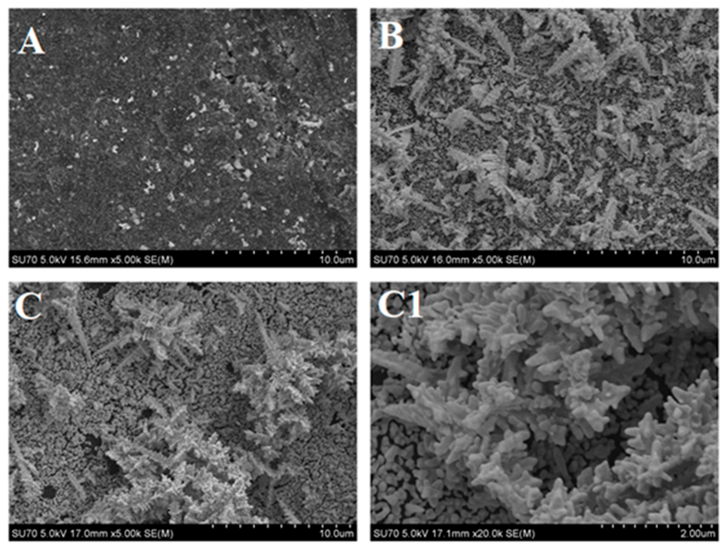
The success of DGNs synthesis depends on a few factors. One of them is the concentration of HAuCl4 in the DGNs synthesis solution. During the electrochemical nucleation and growth process, instantaneous and progressive nucleation are both related to the concentration of HAuCl4 [21,41]. Three concentrations of HAuCl4 −0.02, 3.0 and 6.0 mmol L−1, were selected and tested in this study at a constant −0.2 V potential for 200 s. FE-SEM images show the morphological evaluation of the gold nanostructures formed on the GR electrode changing the concentration of HAuCl4 (Figure 1).
Small AuNPs and aggregates of nanoparticles (diameter about 100 nm) were formed at the lowest 0.02 mmol L−1 concentration of HAuCl4 (Figure 1A). Increasing the concentration of HAuCl4, DGNs were formed on the surface together with AuNPs and aggregates of nanoparticles. Smaller, shorter, and thinner dendrites were formed using 3.0 mmol L−1 concentration of HAuCl4, while bigger, longer, thicker, and with numerous branch DGNs were formed using 6.0 mmol L−1 concentration of HAuCl4 (Figure 1B,C). The clearer view of DGNs is presented in the magnified image of the surface in Figure 1C1.
To select the optimal concentration of HAuCl4 and to develop a glucose biosensor, GOx was immobilized on differently modified electrodes and amperometric measurements were performed. A GR electrode without any modification with gold nanostructures was used as a control.
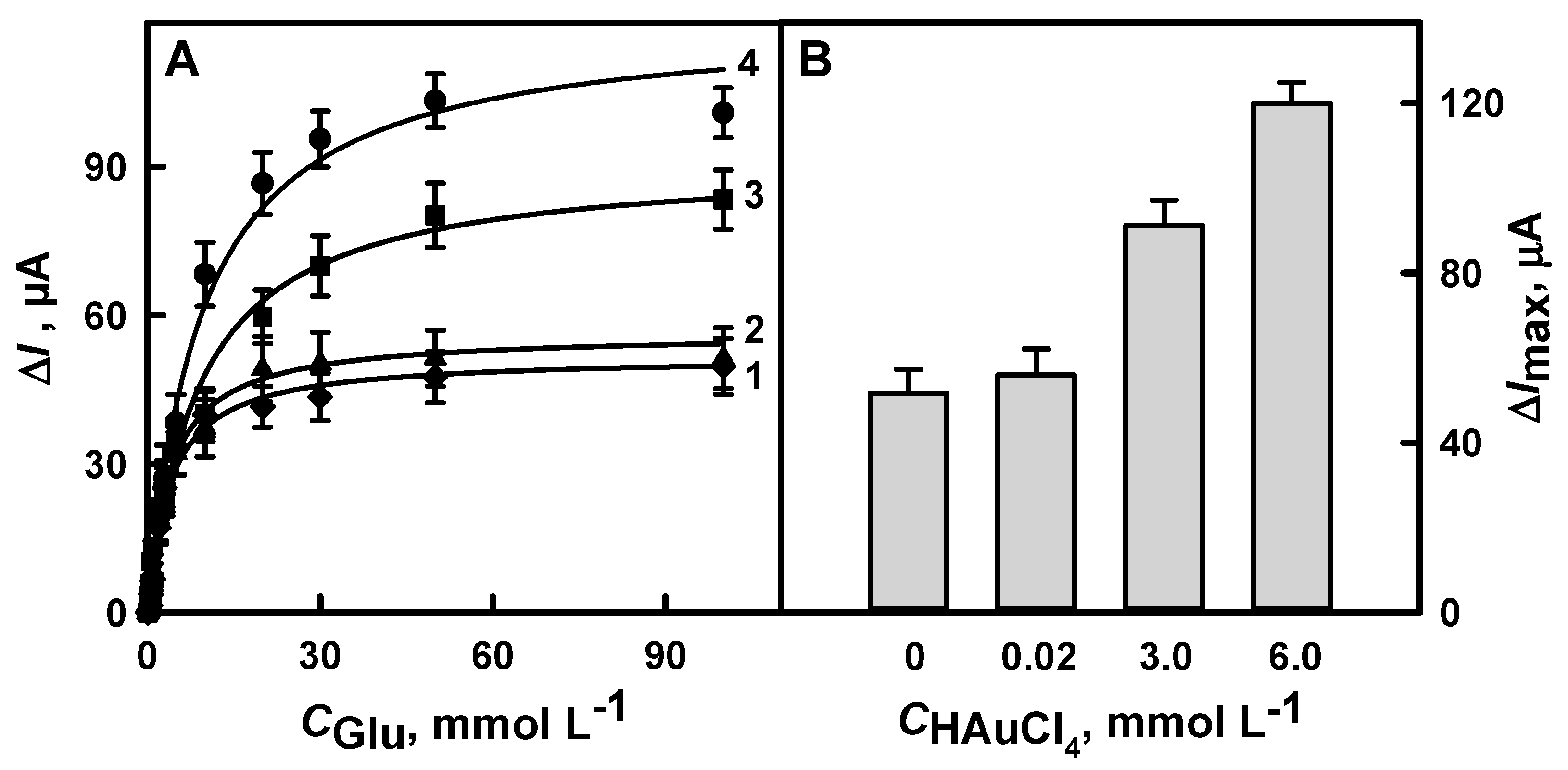
As shown in Figure 2A, the modification of GR electrodes with gold nanostructures has a positive effect in all cases on the performance of glucose biosensor. The highest current response was registered using a GR electrode premodified with DGNs at the highest 6.0 mmol L−1 concentration of HAuCl4. In this case, the ΔImax increased up to 2.3 times in comparison to the GR electrode without any modifications with gold nanostructures. The ΔImax obtained by the electrode premodified with dendrites at 3.0 mmol L−1 concentration of HAuCl4 was 1.8 times higher, while that premodified with AuNPs at 0.02 mmol L−1 concentration of HAuCl4 was only 1.1 times higher if compared with the electrode without gold nanostructures (Figure 2B). Therefore, 6.0 mmol L−1 concentration of HAuCl4 was considered as the optimal concentration for the DGN synthesis and enzymatic glucose biosensor development.

3.1.2. The Selection of the Optimal Time for the Electrochemical Deposition of DGNs

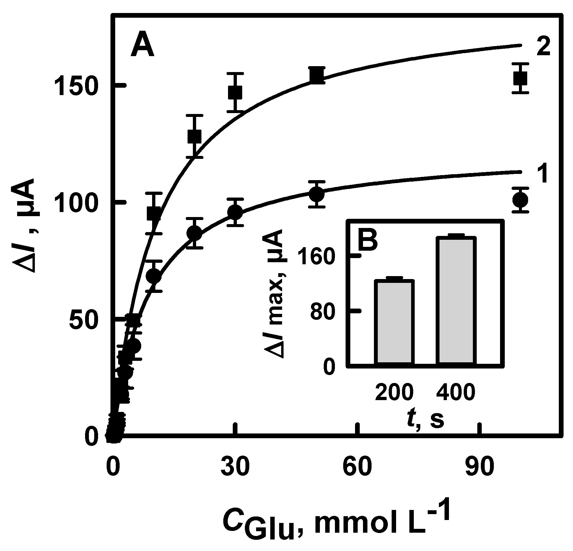
The influence of DGNs electrochemical deposition time on the amperometric signal of the developed biosensors was tested. For this reason, DGNs were electrochemically deposited from 6.0 mmol L−1 concentration of HAuCl4 solution for 200 s and 400 s. As you can see from the results presented in Figure 3, the registered current was higher after a longer 400 s time of synthesis. In this case, the ΔImax was 1.5 times higher than after 200 s electrochemical deposition of DGNs. Thus, 400 s was selected as the optimal time for DGN synthesis.

3.1.3. The Selection of the Optimal Potential for Electrochemical Deposition of DGNs

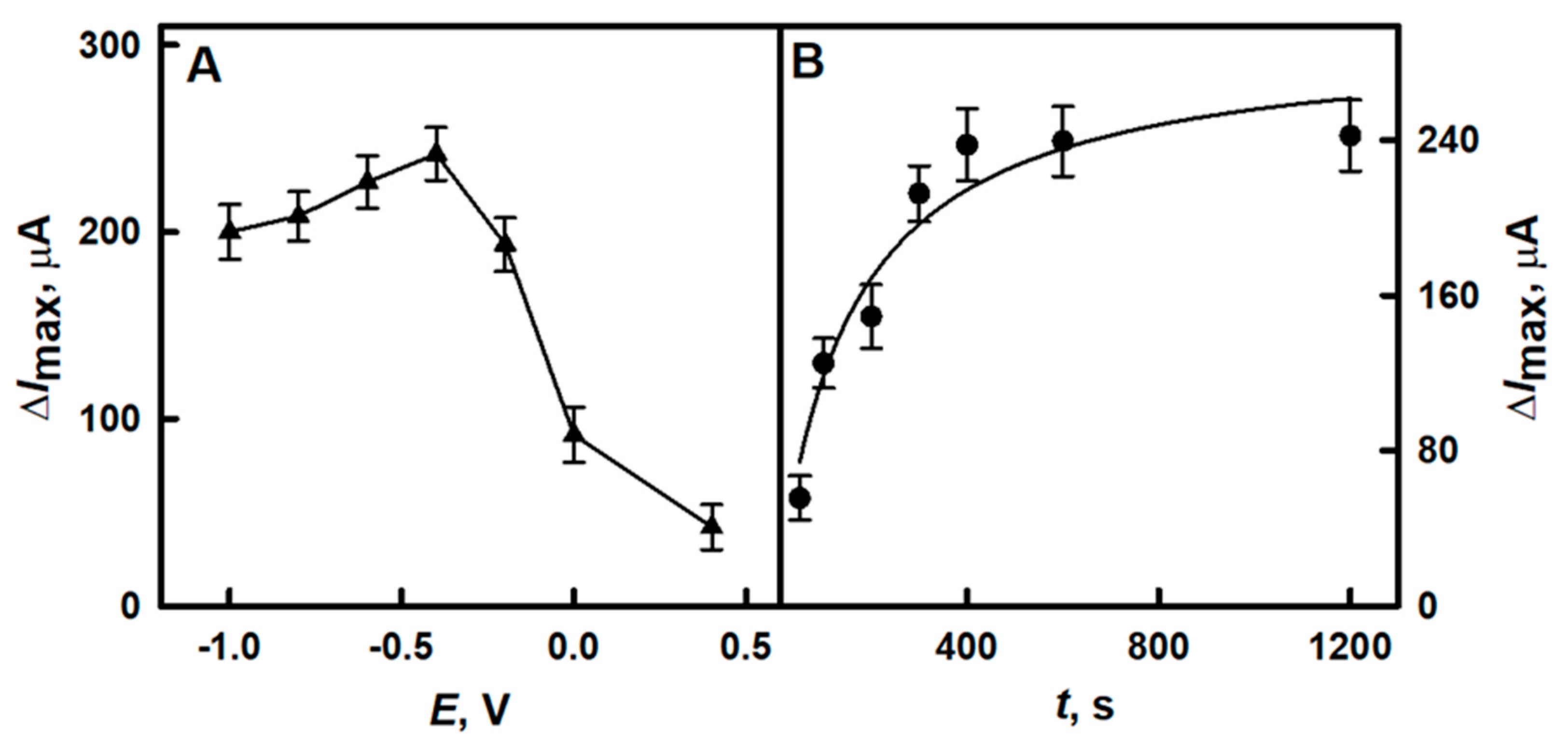
The performance of the glucose biosensor depends on the morphology of the DGNs formed on the GR electrode, so the selection of the optimal potential for this purpose was performed. The ΔImax obtained using biosensors based on a GR electrode premodified with DGNs formed at a constant −0.4 V potential was 242 μA (Figure 4A) and it was 1.3 times higher than using DGNs electrochemically deposited at −0.2 V potential. Additionally, the impact of DGNs electrochemical deposition time at −0.4 V potential on the performance of glucose biosensor was tested. It was obvious from the results presented in Figure 4B, that there was no reason to extend the synthesis of DGNs longer than 400 s usingsolution of 6.0 mmol L−1 HAuCl4 with 0.1 mol L−1 KNO3. In this case, the ΔImax was 1.6 times higher than performing the synthesis of the DGNs for the shorter 200 s period of time.
Summarizing the results obtained during the optimization of DGN synthesis, we can state that the performance of the glucose biosensor was best using the GR electrode premodified with DGNs electrochemically deposited at a constant −0.4 V potential for 400 s using 6.0 mmol L−1 concentration of HAuCl4. The same protocol for the GR electrode modification with DGNs was applied for further glucose biosensor studies. Some authors reported the successful synthesis of DGNs on a glassy carbon electrode at a constant −0.3 V potential for 3600 s using 10.0 mmol L−1 concentration of HAuCl4 [21], while others formed DGNs on a gold electrode at 0.0 mV potential for 600 s using 20 mmol L−1 concentration of HAuCl4 in the presence of histidine [20]. The best conditions for the electrodeposition of DGNs on GC electrode premodified with reduced graphene oxide functionalized by β-lactoglobulin and development of enzymatic glucose biosensor were at −0.4 V potential (vs. Ag/AgCl/KClsat) for 120 s using 5.0 mmol L−1 concentration of HAuCl4 [23].

3.1.4. The Comparison of Glucose Biosensors Developed Using Electrodes Modified with DGNs Synthetized by Different Electrochemical Methods

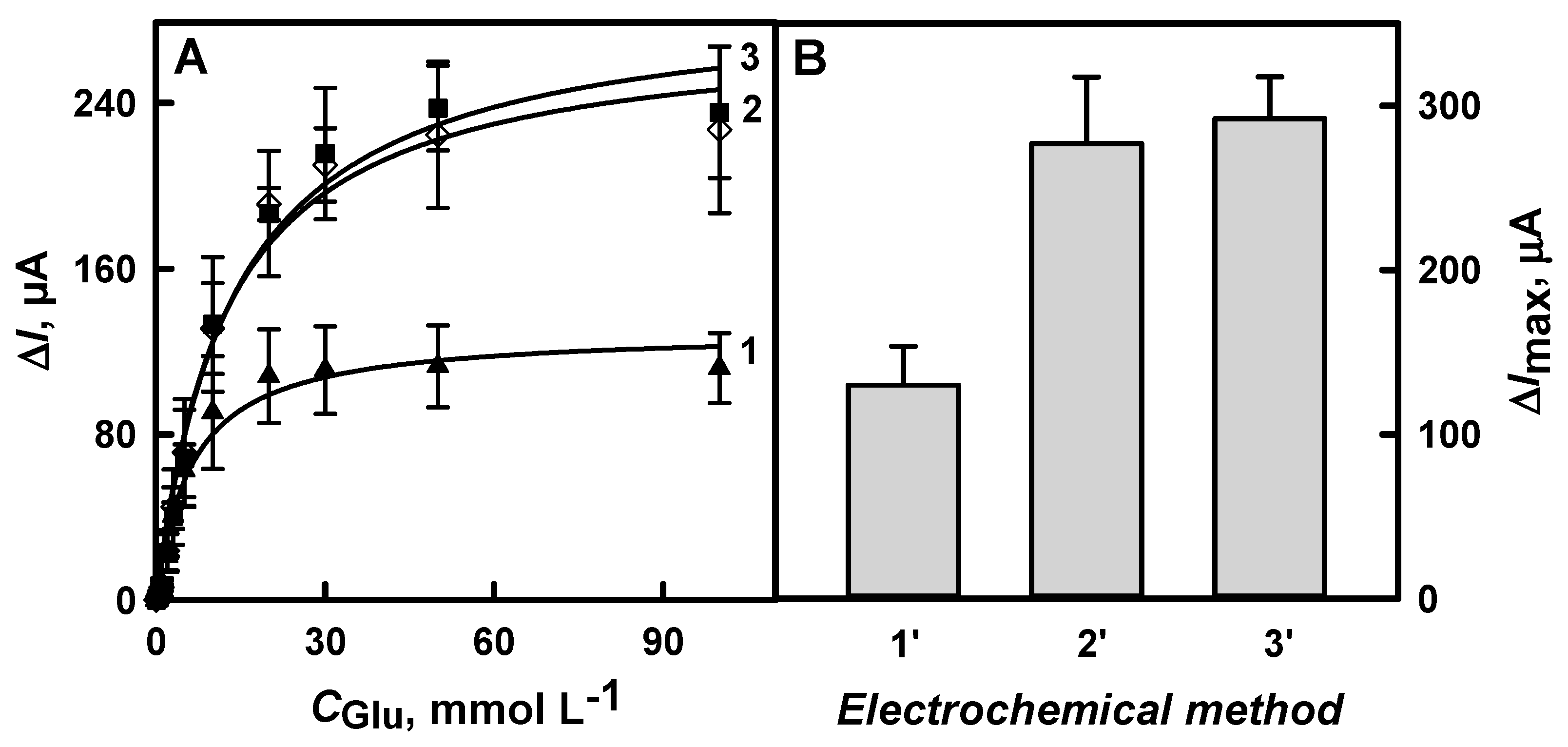
For the selection of the best electrochemical method, the modification of the GR electrode by DGNs was performed using CPA, PA, or DPV. The highest ΔImax (292 μA) of the three developed glucose biosensors was achieved using an electrode premodified with DGNs at a constant −0.4 V potential for 400 s (Figure 5B, 3’). Only slightly lower ΔImax (277 μA) was registered with the electrode premodified with DGNs using DPV method (Figure 5B, 2’). The lowest ΔImax (130 μA) was achieved with the electrode premodified with DGNs using the PA method (Figure 5B, 1’) in the tested glucose concentration range. The ΔImax of the glucose biosensor with an electrode premodified with DGNs electrochemically deposited at a constant potential was 2.2 times higher when compared with the biosensor based on the electrode premodified with gold nanostructures using the PA method. Accordingly, the electrochemical deposition of DGNs on the electrode at a constant −0.4 V potential for 400 s is the best method for the development of a glucose biosensor. Summarizing the publications where DGNs were used for the nonenzymatic detection of glucose, the synthesis of DGNs at a constant potential was used in most cases [13,20,21], while a square-wave technique can also be used [22].
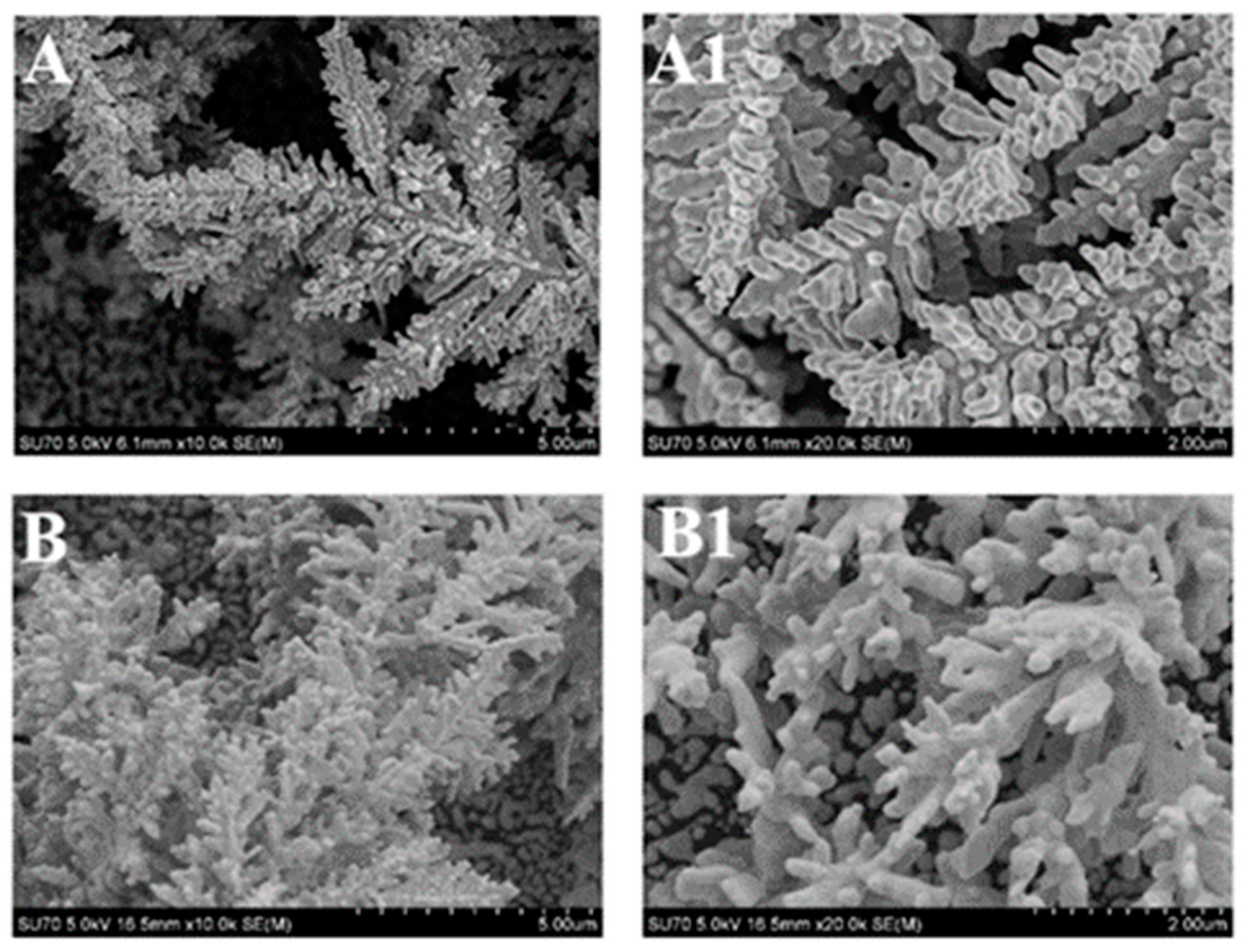
The best results were achieved by two methods, so the morphological evaluation of DGNs formed using CPA, Figure 6A,A1 and DPV, Figure 6B,B1 was performed by FE-SEM. DGNs were formed by both electrochemical methods; however, the detailed image showed differences between them.
Longer, thinner, and more branched DGNs were formed at a constant −0.4 V potential for 400 s. Summarizing the electrochemical results and FE-SEM images, it can be stated that electrochemical deposition of DGNs on the electrode at a constant −0.4 V potential for 400 s is the best method for the development of an enzymatic glucose biosensor, when GOx is adsorbed and covalently cross-linked with glutaraldehyde. This GOx immobilization method was successfully applied using AuNPs of different sizes or electrochemically deposited AuNPs in the development of glucose biosensors [37,39,42]. However, the covalent immobilization of GOx on nanoporous gold using different self-assembled monolayers was also shown [40].

3.2. The Characterization of the Developed Biosensor Based on Electrochemically Deposited DGNs

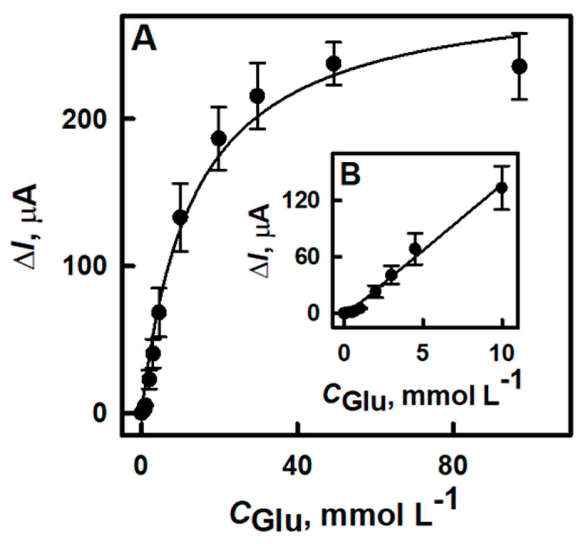
After optimization of the DGN electrochemical deposition on GR electrode conditions and successful immobilization of GOx, the electrochemical performance of the glucose biosensor based on a GOx/DGNs/GR electrode was investigated. The amperometric response to different glucose concentrations was registered in 0.05 mol L−1 SA buffer (pH 6.0) with 2.0 mmol L−1 PMS. During the enzymatic reaction in the presence of the redox mediator, electrons were transferred towards the working electrode surface and the steady-state current was registered at +0.3 V potential vs. Ag/AgCl/KCl 3 mol L−1. The hyperbolic relationship between registered current and glucose concentrations in the range from 0.1 to 97.0 mmol L−1 was obtained (Figure 7A). The ΔImax of the developed biosensor was 291 μA and it was 1.3 times higher than using the biosensor based on electrochemically deposited 13 nm AuNPs (ΔImax = 225 μA) [39] and 2.7, 2.8 and 3.1 times higher than using a biosensor based on immobilized 3.5, 6 and 13 nm AuNPs (ΔImax = 104, 108 and 93.7 μA, respectively) [42]. It should be noted that the performance of the herein compared biosensors was tested at the same potential and using the redox mediator PMS. Additionally, the ΔImax of the developed biosensor was 3.4, 4.1 and 4.4 times higher if compared with the biosensor based on immobilized 3.5, 6 and 13 nm AuNPs in the presence of insoluble mediator—tetrathiafulvalene [37].
The developed biosensor based on DGNs was characterized by a high sensitivity of 12 μA/mmol L −1, short current response time (less than 3 s), and good repeatability—relative standard deviations were 2.4, 2.2 and 1.5% for 2, 30 and 97 mmol L−1 of glucose, respectively. A linear dependence of registered current on glucose concentration was observed from 0.1 to 9.97 mmol L−1 (R2 = 0.9994) (Figure 7B) and it is similar to other published results where AuNPs of different sizes and various enzyme immobilization methods were used [39,43]. For the extension of glucose detection rage, π-π conjugated polymers might be applied [37]. The limit of detection for the developed biosensor was estimated to be as 0.059 mmol L−1 at a signal-to-noise ratio of three and it is satisfactory for the sensitive glucose determination. However, this parameter can be improved using other electrodes and GOx immobilization methods, smaller AuNPs, or other redox mediators. In comparison, the glucose biosensor based on GOx immobilized on DGNs formed on GC electrode premodified with reduced graphene oxide functionalized with β-lactoglobulin was characterized by lower LOD (0.0229 mmol L−1), however, the linear range was only up to 6 mmol L−1 and response time was longer (within 6 s). It should also be mentioned that in this case, the response to glucose at +0.6 V was registered [23]. Amperometric measurements at a high applied potential have a drawback as many endogenous and exogenous compounds, such as uric acid, ascorbic acid, paracetamol, dopamine, and many others present in biological samples can be electrochemically oxidized at a working electrode surface, which can cause significant interference and loss of biosensor accuracy. Electrochemical interference from oxidizable compounds is a serious problem in the practical application of amperometric biosensors with an applied potential of +0.4 V vs. Ag/AgCl or higher [44]. Meanwhile, the lower applied potential significantly reduces or even completely eliminates the effect of electrochemical interference.

3.3. The Stability of the Developed Glucose Biosensor

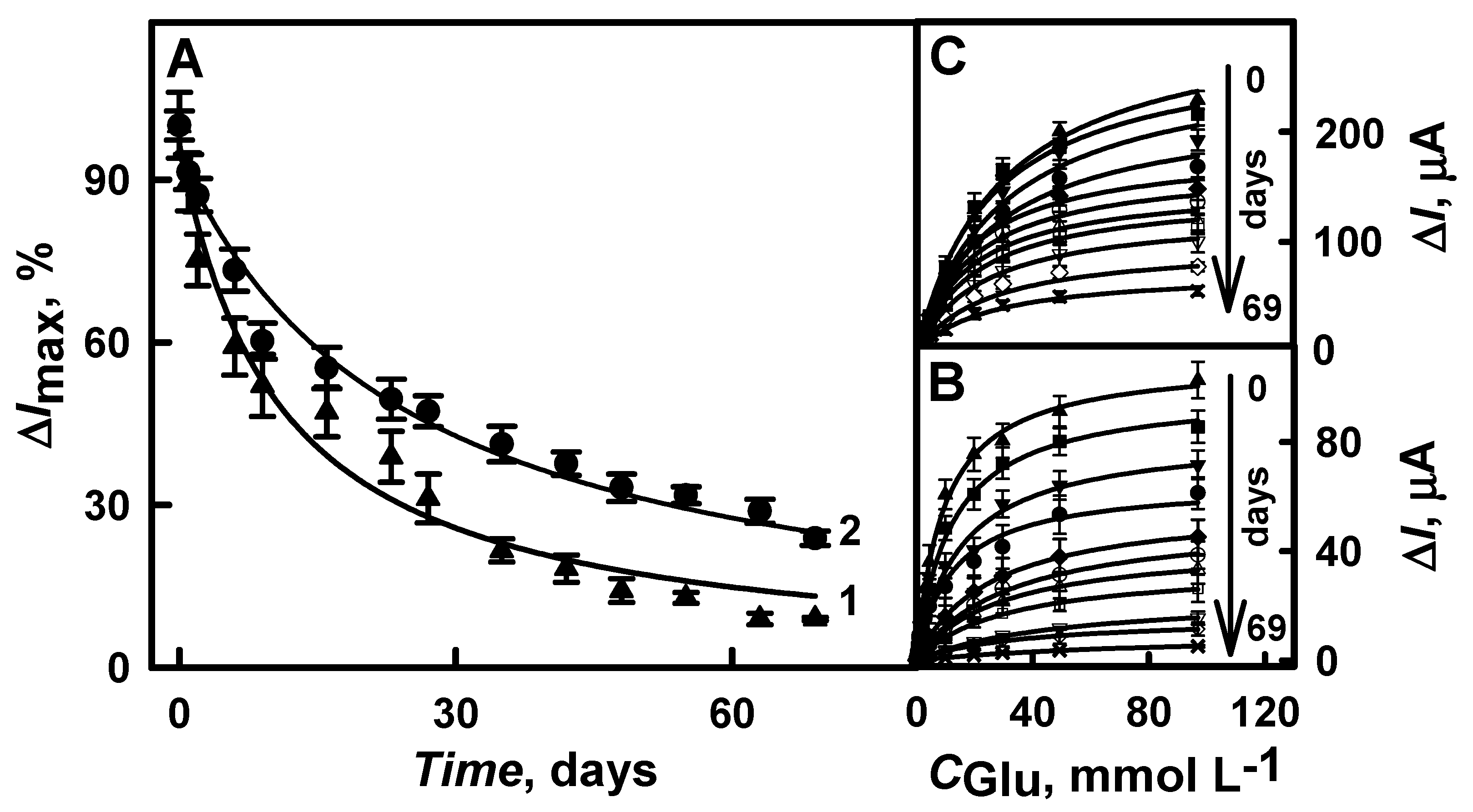
The stability of the glucose biosensor based on the GOx/DGNs/GR electrode was tested during a 69-day period. For comparison, the performance of the biosensor based on GOx/GR electrode was also tested. The ΔImax calculated for both types of biosensors gradually decreased (Figure 8A). However, the biosensor with DGNs was more stable than without any gold nanostructures: 50 % of the initial current response was retained after 22 days, while for the biosensor without AuNPs it was after 11 days. The decrease of current could be affected by desorption of enzyme from the surface and the denaturation of some GOx molecules during the electrochemical measurements. It should be emphasized that DGNs ensure better stability of the enzyme layer on the electrode during repeated measurements and washing, and facilitate the electron transfer between the enzyme redox center and the electrode similar to other types of gold nanostructures [38].

3.4. Application of the Developed Biosensor for the Determination of Glucose in Human Serum

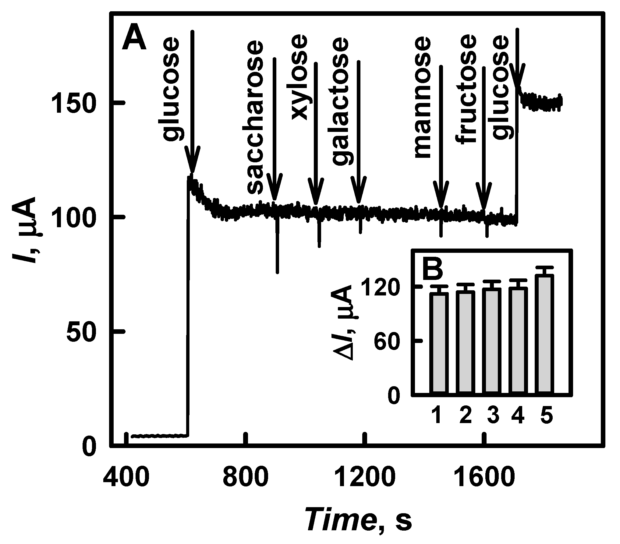
The selectivity of the developed biosensor and the impact of some potentially interfering compounds (they can oxidize on the surface of the working electrode at applied potential) present in real samples on the analytical signal were investigated. The addition of 1.0 mmol L−1 saccharose, xylose, galactose, mannose, or fructose to the solution of 10.0 mmol L−1 glucose had no effect on the registered amperometric responses (Figure 9A). The influence of common interfering substances, such as ascorbic acid and uric acid, on the determination of glucose was also evaluated. It was found that the presence of 0.01 and 0.05 mmol L−1 of ascorbic acid in the solution of 10.0 mmol L−1 glucose increased the analytical signal by 1.78 and 4.46 %, while the presence of 0.01 and 0.1 mmol L−1 of uric acid increased the signal by 5.36 and 17.9 % (Figure 9B). The obtained results suggest that the developed glucose biosensor based on DGNs electrodeposited on a GR electrode is suitable for the selective determination of glucose in the presence of interfering electroactive substances, especially if the sample is diluted during the analysis.
The developed glucose biosensor based on GOx/DGNs/GR electrode was applied for the detection of glucose in human serum diluted with 0.05 mol L−1 SA buffer (pH 6.0) 10 times. Before use, the serum was taken from the freezer, thawed, and centrifuged by IEC CL31R Multispeed centrifuge at 14.6 × 10³ g for 8 min. Electrochemical measurements were performed in diluted human serum after the addition of a known concentration of glucose. Each sample was measured three times, and the results were expressed as average values (Table 1). The recovery of glucose in the human serum was in the range from 94.0 to 98.0% and the relative standard deviation was from 4.39 to 5.63%. Therefore, the developed glucose biosensor based on DGNs could be successfully applied for glucose determination in real samples with sufficient accuracy.

4. Conclusions

In this work, we investigated a one-step electrochemical deposition of DGNs on a GR electrode without any template, seeds, surfactant, or stabilizer using different electrochemical methods, namely, constant potential amperometry, pulse amperometry and differential pulse voltammetry. The electrochemical deposition at constant potential was determined as the best method out of the three herein evaluated electrochemical methods. The optimal conditions for the development of such types of glucose biosensors were elaborated. The developed glucose biosensor showed a linear range up to 9.97 mmol L−1 (dynamic range up to 49 mmol L−1), which is suitable for the diagnosis of diabetes mellitus. Additionally, the performance of the developed biosensor was tested in a real sample. These results proved the principle of enzymatic glucose biosensor development based on DGNs and provide a basis for further improvement using some other enzyme immobilization methods and/or different redox mediators.

Author Contributions

Conceptualization, A.R. (Almira Ramanaviciene); methodology, N.G.; software, N.G.; validation, N.G., A.R. (Almira Ramanaviciene), and A.R. (Arunas Ramanavicius); formal analysis, N.G.; investigation, N.G.; resources, A.K.-M. and A.R. (Almira Ramanaviciene); writing—original draft preparation, N.G., A.K.-M., A.R. (Arunas Ramanavicius) and A.R. (Almira Ramanaviciene); writing—review and editing, A.R. (Arunas Ramanavicius), A.R. (Almira Ramanaviciene); visualization, A.R. (Almira Ramanaviciene); supervision, A.R. (Almira Ramanaviciene); project administration, A.K.-M., and A.R. (Almira Ramanaviciene); funding acquisition, A.K.-M. and A.R. (Almira Ramanaviciene). All authors have read and agreed to the published version of the manuscript.

Funding

This research has received funding from the Research Council of Lithuania (LMTLT), agreement No S-LU-20-11.

Institutional Review Board Statement

Not applicable.

Informed Consent Statement

Not applicable.

Data Availability Statement

Not applicable.

Conflicts of Interest

The authors declare no conflict of interest.

References

  1. Li, N.; Zhao, P.; Astruc, D. Anisotropic gold nanoparticles: Synthesis, properties, applications, and toxicity. Angew. Chem. Int. Ed. 2014, 53, 1756–1789. [Google Scholar] [CrossRef]
  2. Jeerapan, I.; Sonsaard, T.; Nacapricha, D. Applying nanomaterials to modern biomedical electrochemical detection of metabolites, electrolytes, and pathogens. Chemosensors 2020, 8, 71. [Google Scholar] [CrossRef]
  3. Piña, S.; Candia-Onfray, C.; Hassan, N.; Jara-Ulloa, P.; Contreras, D.; Salazar, R. Glassy carbon electrode modified with C/Au nanostructured materials for simultaneous determination of hydroquinone and catechol in water matrices. Chemosensors 2021, 9, 88. [Google Scholar] [CrossRef]
  4. Zou, H.; Ren, G.; Shang, M.; Wang, W. One-step, seedless, fabrication of three-dimensional gold meso-flowers (3D-AuMFs) with high activities in catalysis and surface enhanced Raman scattering. Mater. Chem. Phys. 2016, 176, 115–120. [Google Scholar] [CrossRef]
  5. Cui, Q.; Xia, B.; Mitzscherling, S.; Masic, A.; Li, L.; Bargheer, M.; Möhwald, H. Preparation of gold nanostars and their study in selective catalytic reactions. Colloids Surf. A Physicochem. Eng. Asp. 2015, 465, 20–25. [Google Scholar] [CrossRef]
  6. Feng, J.J.; Lv, Z.Y.; Qin, S.F.; Li, A.Q.; Fei, Y.; Wang, A.J. N-methylimidazole-assisted electrodeposition of Au porous textile-like sheet arrays and its application to electrocatalysis. Electrochim. Acta 2013, 102, 312–318. [Google Scholar] [CrossRef]
  7. Lin, T.H.; Lin, C.W.; Liu, H.H.; Sheu, J.T.; Hung, W.H. Potential-controlled electrodeposition of gold dendrites in the presence of cysteine. Chem. Commun. 2011, 47, 2044–2046. [Google Scholar] [CrossRef] [PubMed]
  8. Zhang, X.; Shi, F.; Yu, X.; Liu, H.; Fu, Y.; Wang, Z.; Jiang, L.; Li, X. Polyelectrolyte multilayer as matrix for electrochemical deposition of gold clusters:  Toward super-hydrophobic surface. J. Am. Chem. Soc. 2004, 126, 3064–3065. [Google Scholar] [CrossRef]
  9. Jia, H.; Chang, G.; Lei, M.; Hec, H.; Liu, X.; Shu, H.; Xia, T.; Su, J.; He, Y. Platinum nanoparticles decorated dendrite-like gold nanostructure on glassy carbon electrodes for enhancing electrocatalysis performance to glucose oxidation. Appl. Surf. Sci. 2016, 384, 58–64. [Google Scholar] [CrossRef]
  10. Yi, S.; Sun, L.; Lenaghan, S.C.; Wang, Y.; Chong, X.; Zhang, Z.; Zhang, M. One-step synthesis of dendritic gold nanoflowers with high surface-enhanced Raman scattering (SERS) properties. RSC Adv. 2013, 3, 10139–10144. [Google Scholar] [CrossRef]
  11. Huang, T.; Meng, F.; Qi, L. Controlled synthesis of dendritic gold nanostructures assisted by supramolecular complexes of surfactant with cyclodextrin. Langmuir 2010, 26, 7582–7589. [Google Scholar] [CrossRef] [PubMed]
  12. Hu, Y.; Pan, N.; Zhang, K.; Wang, Z.; Hu, H.; Wang, X. Fabrication of dendrite-like Au nanostructures and their enhanced photoluminescence emission. Phys. Stat. Sol. A 2007, 204, 3398–3404. [Google Scholar] [CrossRef]
  13. Shanmugam, M.; Kim, K. Electrodeposited gold dendrites at reduced graphene oxide as an electrocatalyst for nitrite and glucose oxidation. J. Electroanal. Chem. 2016, 776, 82–92. [Google Scholar] [CrossRef]
  14. Pang, S.; Kondo, T.; Kawai, T. Formation of dendrimer-like gold nanoparticle assemblies. Chem. Mater. 2005, 17, 3636–3641. [Google Scholar] [CrossRef]
  15. Bai, X.; Gao, Y.; Zheng, L. Galvanic replacement mediated growth of dendritic gold nanostructures with a three-fold symmetry and their applications to SERS. Cryst. Eng. Comm. 2011, 13, 3562–3568. [Google Scholar] [CrossRef]
  16. Lee, J.H.; Kamada, K.; Enomoto, N.; Hojo, J. Seeding method for three-dimensional dendritic growth of gold nanoparticles stabilized by hexatrimethylammonium bromide. Chem. Lett. 2007, 36, 728–729. [Google Scholar] [CrossRef]
  17. Zhang, J.; Meng, L.; Zhao, D.; Fei, Z.; Lu, Q.; Dyson, P.J. Fabrication of dendritic gold nanoparticles by use of an ionic polymer template. Langmuir 2008, 24, 2699–2704. [Google Scholar] [CrossRef]
  18. Tang, X.L.; Jiang, P.; Ge, G.L.; Tsuji, M.; Xie, S.S.; Guo, Y.J. Poly(N-vinyl-2-pyrrolidone) (PVP)-capped dendritic gold nanoparticles by a one-step hydrothermal route and their high SERS effect. Langmuir 2008, 24, 1763–1768. [Google Scholar] [CrossRef]
  19. Wu, Y.; Liu, K.; Su, B.; Jiang, L. Superhydrophobicity-mediated electrochemical reaction along the solid-liquid -gas triphase interface: Edge-growth of gold architectures. Adv. Mater. 2014, 26, 1124–1128. [Google Scholar] [CrossRef]
  20. Heli, H.; Amirizadeh, O. Non-enzymatic glucose biosensor based on hyperbranched pine-like gold nanostructures. Mater. Sci. Eng. C 2016, 63, 150–154. [Google Scholar] [CrossRef] [Green Version]
  21. Shu, H.; Cao, L.; Chang, G.; He, H.; Zhang, Y.; He, Y. Direct electrodeposition of gold nanostructures onto glassy carbon electrodes for non-enzymatic detection of glucose. Electrochim. Acta 2014, 132, 524–532. [Google Scholar] [CrossRef]
  22. Das, A.K.; Samdani, J.; Kim, H.Y.; Lee, J.H. Nicotinamide adenine dinucleotide assisted direct electrodeposition of gold nanodendrites and its electrochemical application. Electrochim. Acta 2015, 158, 129–137. [Google Scholar] [CrossRef]
  23. Du, X.; Zhang, Z.; Miao, Z.; Ma, M.; Zhang, Y.; Zhang, C.; Wang, W.; Han, B.; Chen, Q. One step electrodeposotion of dendritic gold nanostructures on β-lactoglobulin-functionalized reduced graphene oxide for glucose sensing. Talanta 2015, 144, 823–829. [Google Scholar] [CrossRef]
  24. Hau, N.Y.; Yang, P.; Liu, C.; Wang, J.; Lee, P.H.; Feng, S.P. Aminosilane-assisted electrodeposition of gold nanodendrites and their catalytic properties. Sci. Rep. 2017, 7, 39839. [Google Scholar] [CrossRef]
  25. Purohit, B.; Kumar, A.; Mahato, K.; Chandra, P. Novel sensing assembly comprising engineered gold dendrites and MWCNT-AuNPs nanohybrid for acetaminophen detection in human urine. Electroanalysis 2020, 32, 561–570. [Google Scholar] [CrossRef]
  26. Rafatmah, E.; Hemmateenejad, B. Dendrite gold nanostructures electrodeposited on paper fibers: Application to electrochemical non-enzymatic determination of glucose. Sens. Actuators B Chem. 2020, 304, 127335. [Google Scholar] [CrossRef]
  27. Zaki, M.H.M.; Mohd, Y.; Chin, L.Y. Surface properties of nanostructured gold coatings electrodeposited at different potentials. Int. J. Electrochem. Sci. 2020, 15, 11401–11415. [Google Scholar] [CrossRef]
  28. Feng, J.J.; Li, A.Q.; Lei, Z.; Wang, A.J. Low-potential synthesis of “clean” Au nanodendrites and their high performance toward ethanol oxidation. ACS Appl. Mater. Inerfaces 2012, 4, 2570–2576. [Google Scholar] [CrossRef]
  29. Lv, Z.Y.; Li, A.Q.; Fei, Y.; Li, Z.; Chen, J.R.; Wang, A.J.; Feng, J.J. Facile and controlled electrochemical route to three-dimensional hierarchical dendritic gold nanostructures. Electrochim. Acta 2013, 109, 136–144. [Google Scholar] [CrossRef]
  30. Chen, W.Y.; Mei, L.P.; Feng, J.J.; Yuan, T.; Wang, A.J.; Yu, H. Electrochemical determination of bisphenol A with a glassy carbon electrode modified with gold nanodendrites. Microchim. Acta 2015, 182, 703–709. [Google Scholar] [CrossRef]
  31. Huan, T.N.; Ganesh, T.; Kim, K.S.; Kim, S.; Han, S.H.; Chung, H. A three-dimentional gold nanodendrites network porous structure and its application for an electrochemical sensing. Biosens. Bioelectron. 2011, 27, 183–186. [Google Scholar] [CrossRef]
  32. Ye, W.; Yan, J.; Ye, Q.; Zhou, F. Template-free and direct electrochemical deposition of hierarchical dendritic gold microstructures: Growth and their multiple applications. J. Phys. Chem. C 2010, 114, 15617–15624. [Google Scholar] [CrossRef]
  33. Xiao, Y.; Liu, J.; Huang, W.; Li, Z. Electrochemical fabrication of clean dendritic Au supported Pt clusters for electrocatalytic oxidation of formic acid. Electrochim. Acta 2012, 70, 304–312. [Google Scholar] [CrossRef]
  34. Valera, A.E.; Nesbitt, N.T.; Archibald, M.M.; Naughton, M.J.; Chiles, T.C. On-chip electrochemical detection of cholera using a polypyrrole-functionalized dendritic gold sensor. ACS Sens. 2019, 4, 654–659. [Google Scholar] [CrossRef] [PubMed]
  35. Vassilyev, Y.B.; Khazova, O.A.; Nikolaeva, N.N. Kinetics and mechanism of glucose electrooxidation on different electrode-catalysts part II. Effect of the nature of the electrode and the electrooxidation mechanism. J. Electroanal. Chem. 1985, 196, 127–144. [Google Scholar] [CrossRef]
  36. Lee, W.C.; Kim, K.B.; Gurudatt, N.G.; Hussain, K.K.; Choi, C.S.; Park, D.S.; Shim, Y.B. Comparison of enzymatic and non-enzymatic glucose sensors based on hierarchical Au-Ni alloy with conductive polymer. Biosens. Bioelectron. 2019, 130, 48–54. [Google Scholar] [CrossRef]
  37. German, N.; Kausaite-Minkstimiene, A.; Ramanavicius, A.; Semashko, T.; Mikhailova, R.; Ramanaviciene, A. The use of different glucose oxidases for the development of an amperometric reagentless glucose biosensor based on gold nanoparticles covered by polypyrrole. Electrochim. Acta 2015, 169, 326–333. [Google Scholar] [CrossRef]
  38. Ramanavicius, A.; German, N.; Ramanaviciene, A. Evaluation of electron transfer in electrochemical system based on immobilized gold nanoparticles and glucose oxidase. J. Electrochem. Soc. 2017, 164, G45–G49. [Google Scholar] [CrossRef]
  39. German, N.; Ramanavicius, A.; Ramanaviciene, A. Electrochemical deposition of gold nanoparticles on graphite rod for glucose biosensing. Sens. Actuat. B Chem. 2014, 203, 25–34. [Google Scholar] [CrossRef]
  40. Xiao, X.; Li, H.; Wang, M.; Zhang, K.; Si, P. Examining the effects of self-assembled monolayers on nanoporous gold based amperometric glucose biosensors. Analyst 2014, 139, 488–494. [Google Scholar] [CrossRef]
  41. Scharifker, B.; Hills, G. Theoretical and experimental studies of multiple nucleation. Electrochim. Acta 1983, 28, 879–889. [Google Scholar] [CrossRef]
  42. German, N.; Ramanaviciene, A.; Voronovic, J.; Ramanavicius, A. Glucose biosensor based on graphite electrodes modified with glucose oxidase and colloidal gold nanoparticles. Microchim. Acta 2010, 168, 221–229. [Google Scholar] [CrossRef]
  43. Yang, W.; Wang, J.; Zhao, S.; Sun, Y.; Sun, C. Multilayered construction of glucose oxidase and gold nanoparticles on Au electrodes based on layer-by-layer covalent attachment. Electrochem. Commun. 2006, 8, 665–672. [Google Scholar] [CrossRef]
  44. Yuan, C.J.; Hsu, C.L.; Wang, S.C.; Chang, K.S. Eliminating the interference of ascorbic acid and uric acid to the amperometric glucose biosensor by cation exchangers membrane and size exclusion membrane. Electroanalysis 2005, 17, 2239–2245. [Google Scholar] [CrossRef]
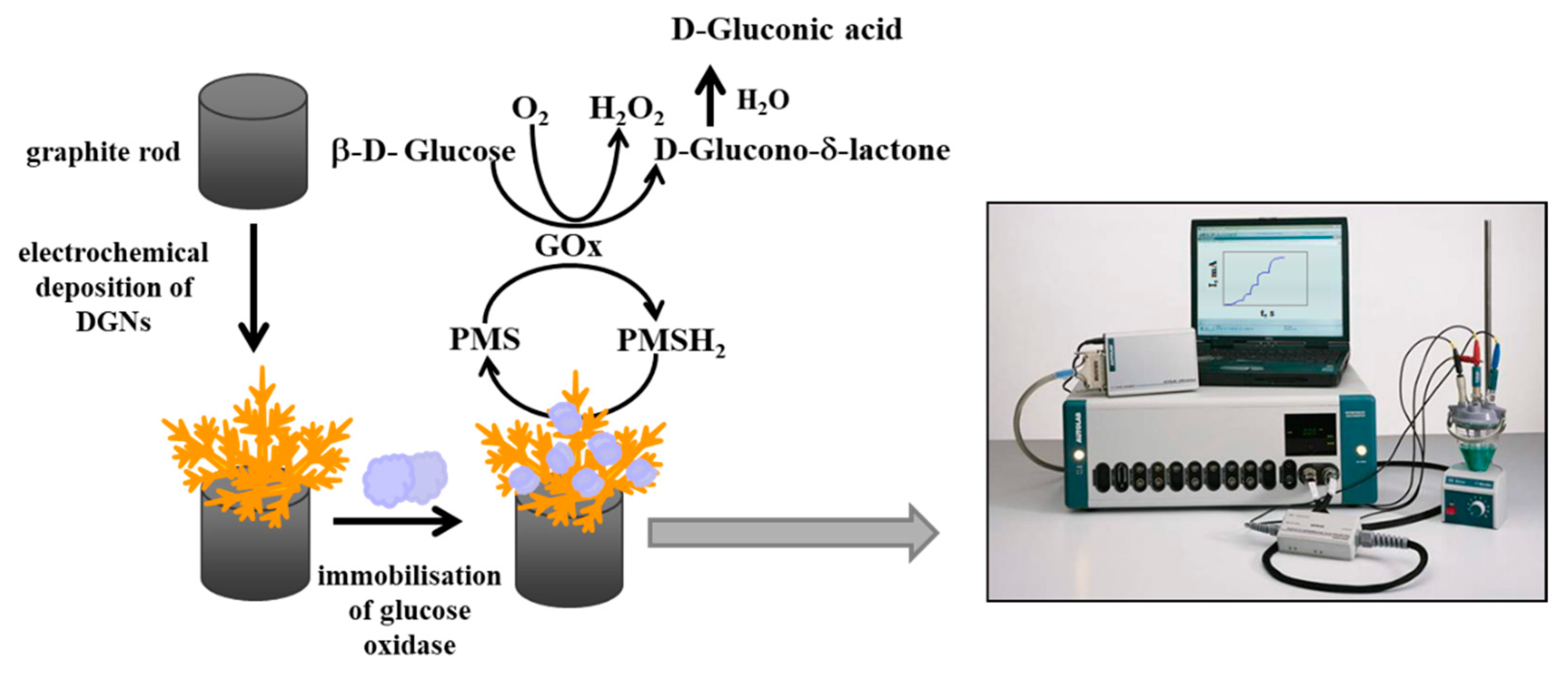
Scheme 1. Schematic representation of electrochemical DGNs deposition on graphite rod electrodes followed by glucose oxidase immobilisation and glucose determination by the developed biosensor.
Chemosensors 09 00188 sch001
Figure 1. SEM images of the gold nanostructures electrochemically deposited on a graphite rod at constant −0.2 V potential for 200 s in the solution of 0.1 mol L−1 KNO3 containing different concentrations of HAuCl4: (A) 0.02, (B) 3.0, and (C) 6.0 mmol L−1 ((C1) magnified image of picture (C)).
Chemosensors 09 00188 g001
Figure 2. Calibration plots (A) and diagrams (B) of glucose biosensors based on DGNs electrochemically deposited using different concentrations of HAuCl4 solution. Electrochemical deposition of gold nanostructures was performed in a solution of 0.1 mol L−1 KNO3 containing 0, 0.02, 3.0 or 6.0 mmol L−1 of HAuCl4 (curves 1, 2, 3 and 4, respectively) at constant −0.2 V potential for 200 s. Amperometric response was measured in 0.05 mol L−1 SA buffer with 0.1 mol L−1 KCl (pH 6.0) and 2.0 mmol L−1 PMS.
Chemosensors 09 00188 g002
Figure 3. Calibration plots (A) and diagrams (B) of glucose biosensors based on DGNs electrochemically deposited for different periods of time. Electrochemical deposition of DGNs was performed in a solution of 6 mmol L−1 HAuCl4 with 0.1 mol L−1 KNO3 at constant −0.2 V potential for 200 s (curve 1) and 400 s (curve 2).
Chemosensors 09 00188 g003
Figure 4. The effect of applied potential (A) and the duration (B) of electrochemical deposition of DGNs on currents registered by glucose biosensors. (A) Electrochemical deposition of DGNs was performed in the solution of 6 mmol L−1 HAuCl4 with 0.1 mol L−1 KNO3 at different potentials for 400 s; (B) Electrochemical deposition of DGNs was performed at constant −0.4 V potential for different period of time.
Chemosensors 09 00188 g004
Figure 5. Calibration plots (A) and diagrams (B) of glucose biosensors based on DGNs electrochemically deposited on the electrode using different electrochemical methods: 1, 1’—pulse amperometry; 2, 2’—differential pulse voltammetry; 3, 3’—constant potential amperometry. Synthesis of DGNs was performed in the solution of 6 mmol L−1 HAuCl4 with 0.1 mol L−1 KNO3.
Chemosensors 09 00188 g005
Figure 6. FE-SEM images of DGNs on the electrode surface obtained after electrochemical deposition using CPA (A,A1) and DPV methods (B,B1). Synthesis of DGNs was performed in the solution of 6 mmol L−1 HAuCl4 with 0.1 mol L−1 KNO3.
Chemosensors 09 00188 g006
Figure 7. Calibration plot of glucose biosensors based on DGNs electrochemically deposited on the electrode at optimal conditions (A) and linear glucose detection interval (B). Amperometric response was measured in 0.05 mol L−1 SA.
Chemosensors 09 00188 g007
Figure 8. The stability (A) and calibration plots of GOx/GR (1 curve and B) and GOx/DGNs/GR (2 curve and C) electrodes. Amperometric response was measured in 0.05 mol L−1 SA buffer with 0.1 mol L−1 KCl (pH 6.0) and 2.0 mmol L−1 PMS.
Chemosensors 09 00188 g008
Figure 9. The effect of interfering substances on the amperometric response of the developed glucose biosensor. (A)—Amperogram registered in 10 times diluted human serum sample after an addition of the 10.0 mmol L−1 glucose, 1.0 mmol L−1 saccharose, xylose, galactose, mannose or fructose. (B)—Diagram of registered currents in 10 times diluted human serum after an addition of 10.0 mmol L−1 glucose (column 1); 10.0 mmol L−1 glucose with 0.01 mmol L−1 ascorbic acid (column 2); 10.0 mmol L−1 glucose with 0.05 mmol L−1 ascorbic acid (column 3); 10.0 mmol L−1 glucose with 0.01 mmol L−1 uric acid (column 4); 10.0 mmol L−1 glucose with 0.1 mmol L−1 uric acid (column 5). Amperometric response was measured in 0.05 mol L−1 SA buffer (pH 6.0) with 2.0 mmol L−1 PMS.
Chemosensors 09 00188 g009
Table 1. Recovery of glucose in human serum using an electrochemical biosensor based on GOx/DGNs/GR electrode. (n—number of measurements) *.
Added Concentration, mmol L−1Detected Concentration (n = 3), mmol L−1Relative Standard
Deviation, %
Recovery Ratio, %
0.5000.4705.6394.0
1.000.9604.9196.0
2.001.954.8197.5
3.002.944.3998.0
* Amperometric response was measured in human serum diluted 10 times with 0.05 mol L−1 SA buffer (pH 6.0) in the presence of 2 mmol L−1 PMS at +0.3 V vs. Ag/AgCl/KCl 3 mol L−1.
Publisher’s Note: MDPI stays neutral with regard to jurisdictional claims in published maps and institutional affiliations.