Article

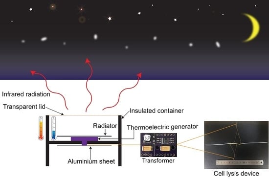
Off-Grid Electrical Cell Lysis Microfluidic Device Utilizing Thermoelectricity and Thermal Radiation

Department of BioNano Technology, Gachon University, 1342 Seongnam-daero, Sujeong-gu, Seongnam-si 13120, Korea
*
Author to whom correspondence should be addressed.
Chemosensors 2021, 9(10), 292; https://doi.org/10.3390/chemosensors9100292
Submission received: 14 September 2021 / Revised: 11 October 2021 / Accepted: 12 October 2021 / Published: 14 October 2021
(This article belongs to the Special Issue Microfluidic Biosensing Platform)

Abstract

:
Microfluidic devices have enormous potential and a wide range of applications. However, most applications end up as chip-in-a-lab systems because of power source constraints. This work focuses on reducing the reliance on the power network and expanding on the concept of a lab-on-a-chip for microfluidic devices. A cellulose-based radiator to reflect infrared (IR) radiation with wavelengths within the atmospheric window (8–13 µm) into outer space was fabricated. This process lowered the temperature inside the insulated environment. The difference in temperature was used to power a thermoelectric generator (TEG) and generate an electric current. This electric current was run through a DC-DC transformer to increase the voltage before being used to perform electrical cell lysis with a microfluidic device. This experimental setup successfully achieved 90% and 50% cell lysis efficiencies in ideal conditions and in field tests, respectively. This work demonstrated the possibility of utilizing the unique characteristics of a microfluidic device to perform an energy-intensive assay with minimal energy generated from a TEG and no initial power input for the system. The TEG system also required less maintenance than solar, wind, or hydroelectricity. The IR radiation process naturally allows for more dynamic working conditions for the entire system.

Graphical Abstract

1. Introduction

Microfluidic devices have been the focal point of many technologies, with promising concepts such as lab-on-chip [1], organ-on-chip, and human-on-chip systems [2,3], with the aim of creating eco-friendly, material-efficient, and energy-efficient testing platforms [4,5,6]. However, the potential of microfluidic devices is limited because of their dependency on large and bulky support machines. Moreover, power source requirements also limit the extensive usage of microfluidic devices in remote areas with little to no access to conventional power networks. Additionally, common alternative power sources, such as solar and wind power, are bulky, expensive, and labor-intensive to set up and maintain [7]. These financial and labor costs are not suitable for remote areas where these technologies are needed the most. However, thermoelectricity is a promising solution for this conundrum. Thermal energy can be converted directly into electric energy using a thermoelectric generator (TEG). Each thermocouple is composed of two different materials with opposite Seebeck coefficients. Thus, a TEG contains neither moving parts nor chemicals. This characteristic enables TEGs to function reliably in harsh environments with negligible maintenance and have a limited effect on the environment. Furthermore, owing to these advantages, considerable research has been devoted toward the potential of integrating TEGs into fabrics and accessories to harvest wasted body heat for powering small devices [8,9,10,11,12,13,14,15,16,17]. Although TEG-woven fabrics have significant potential applications, they are uncommon and expensive. Furthermore, actively maintaining a constant difference in temperature between the two sides of the TEG consumes more energy than the amount of energy generated by the TEG. Therefore, passively cooling one side of the TEG is a promising solution for achieving a temperature gradient. The improvement of technology has widened the range of applications for this type of passive radiative cooling [18,19,20]. The passive cooling process can be realized by exploiting the gap in the infrared (IR) absorption spectrum of the atmosphere, commonly called the IR atmospheric window. The atmosphere is transparent for wavelengths ranging from 8 to 13 µm. The thermal energy of the object is passively and slowly radiated in the form of IR radiation to outer space through the IR atmospheric window [21,22]. If IR radiation removes more thermal energy than the total thermal energy gain from the ambient environment, the object will be cooled [23,24]. A carefully insulated container with an IR emitter inside can reduce the interior temperature to a sub-ambient or below freezing temperature under direct sunlight when the interior of the container is a near vacuum [25,26,27]. Many strategies have been implemented to fabricate and optimize the efficiency of IR radiators. These methods include optimizing IR emissivity via the stimulation and fabrication of a multilayered coating, altering the nature of the material, carefully modifying the nano/microstructure of the surface, or a combination of these approaches to maximize the IR emissions [23,25,28,29,30,31,32,33,34,35,36,37,38].
In a remote area, identifying a sample using molecular diagnostics is not an easy task [39,40]. The lack of equipment and specialized chemicals make the use of conventional cell lysis methods to extract cells’ contents an insurmountable challenge. Electrical cell lysis, on the other hand, does not require specialized chemicals. Thus, it is a simpler, quicker, and less expensive approach for extracting cell molecules. This process uses a strong external electric field to disrupt and open pores in the cell membrane. The cell’s contents flow out, partially owing to the external electrical field. Because membrane disruption agent is not added, the product can be used directly without the need to eliminate the added chemicals. The entire cell lysis process is fast, effective, and labor saving, compared to other methods such as using mechanical force or heat shock. However, electrical cell lysis requires a high voltage for operation [41]. Fortunately, the development of microfluidic technology has enabled the use of minimal voltages to create an external electrical field sufficient to overcome the critical threshold to disintegrate cell membranes [42,43,44,45].
In this study, a small power station was built using a conventional TEG as the main power generator. The TEG was powered by the heat flux generated by reflecting IR radiation, with wavelengths within the atmospheric window, into outer space. The output of the TEG was then stepped up using a DC-DC transformer system and employed to perform electrical cell lysis in a microfluidic device. The final goal of this work is to offer a solution for the power network dependency when operating a microdevice. The concept is illustrated in Figure 1.
In Section 1, a short introduction about the potential of the microfluidic device and the current power source constraints were introduced. The working principle of the TEG, radiative cooling, and electrical cell lysis technique are described. Section 2 presents the materials and the methods used to fabricate and set up the power station and the microdevice. Section 3 discusses on the results. Section 4 describes the advantages and disadvantages, as well as possible future improvement.

2. Materials and Methods

The power station used a TEG as the generator. An IR radiator was employed to power the TEG. The electric current generated by the TEG was amplified by a DC-DC transformer system for the operation of the electrical cell lysis microdevice.

2.1. Materials

An ultra-low voltage boost converter model, MCU-3108 LTC-3108-1, was purchased from Analog Devices Inc., Wilmington, MA, USA. A transformer (ratio 1:100), LPR6235-752SMRB, was purchased from Coilcraft, Taiwan. A CPM-2C Peltier was purchased from CUI devices, Lake Oswego, OR, USA. HeLa cells, trypan blue solution, carbon paste, and silver paste were purchased from Sigma-Aldrich, St. Louis, MO, USA. Dulbecco’s Modified Eagle Medium (DMEM), penicillin-streptomycin solution (1:100), fetal bovine serum (FBS), Ca2+ and Mg2+-free salt solution, Dulbecco’s phosphate-buffered saline (DPBS) (1×, pH 7.4), trypsin/EDTA solution (0.25%), and trypsin neutralization solution were purchased from Sciencell Research Laboratories, Carlsbad, CA, USA. Hemocytometers were purchased from INCYTO, Republic of Korea. PDMS prepolymer (Sylgard 184) and a curing agent were purchased from Dow Corning, Midland, MI, USA.

2.2. Methods

2.2.1. Cell Culture and Harvesting

HeLa cells were seeded in a commercialized Petri dish at a concentration of 105 cells/mL, after which the cells were incubated in a humidified incubator at 37 °C and 5% CO2. The cells were cultured in DMEM and 10% FBS, and the cell medium was exchanged every two days. When confluency reached approximately 90%, DMEM was aspirated, and the cells were gently rinsed with DBPS. Subsequently, the trypsin/EDTA solution was added until the culture surface was completely covered. The dish was incubated at 37 °C for 1–3 min. The morphology of the cells was periodically monitored under a microscope until approximately 90% of the cells were detached from the cultured surface. Then, a trypsin-neutralizing solution was added. Next, the wall of the vessel was gently tapped to dislodge the remaining cells. The solution was then transferred into centrifuge tubes and centrifuged at 1000 rpm for 5 min at 10 °C. The suspension was discarded. The cells were resuspended in DMEM based on the usage. Finally, the cells were seeded at a concentration of 105 cells/cm2 in DMEM in a new culture vessel.

2.2.2. Fabrication of Cell Electrical Lysis Device

The device has a simple structure, as shown in the schematic Figure 2a. The first component of this device is a silicone tube with an outer diameter of 2.0 mm and an inner diameter of 1.0 mm. The second component is the electrodes. The electrodes were four hollow brass tubes with an outer diameter of 1.2 mm and an inner diameter of 1 mm. Figure 2b shows the scale and overall structure of the complete device. To fabricate the device, first, the silicone tube was cut to a suitable length to connect the electrodes. Second, the electrodes were inserted inside the silicone tube. Each electrode was positioned 0.5 mm apart. Then, each electrode was connected using separate wires. The cathode and anode were alternately connected to electrodes using a copper wire, as shown in Figure 2c. The device was designed to take full advantage of the characteristics of the microfluidic device, such as its small size, low cost per unit, and minimal use of samples. Conventional electrical cell lysis devices draw a large amount of energy from the power network to create a strong electrical field to disrupt the cell membrane. Conversely, microfluidic devices use a significantly smaller amount of power with a low voltage input. The microfluidic configuration enabled the electrodes to be placed at smaller intervals. This placement exponentially increases the strength of the electrical field in the microchannel without the need to increase the voltage. The constrictions in the channel also increase the strength of the electrical field to an adequate threshold to disrupt the cell membrane [46,47,48,49]. Additionally, empirical results have shown that a longer duration of direct current releases more cell contents [50].

2.2.3. Fabrication of Radiator

Figure 3a shows the layer composition of the radiator and fabrication process. As shown in Figure 3b, the radiator was fabricated from a base of a commercial cellulose fiber of size A4. First, a layer of carbon paste was carefully painted on the cellulose fiber sheet, leaving no gaps on the sheet when observed over a light source. This cellulose sheet was then allowed to dry in a convection oven at 80 °C for 30 min. The result of this process is shown in Figure 3c. Second, 10 g of the PDMS prepolymer and a curing agent were mixed at a ratio of 10:1 (w/w), and the mixture was spread evenly over the surface of the sheet. The result can be seen in Figure 3d. After the PDMS layer was cured at 80 °C for 30 min, the silver paste was coated on the surface of the PDMS layer. Figure 3e shows the final form of the radiator.

2.2.4. Fourier-Transform Infrared Spectroscopy (FT-IR) Analysis

The radiator was analyzed using an FT-IR analyzer (660-IR Varian, Allegiant Technologies). The absorptivity and emissivity of IR radiation ranging from 2.5 to 25 µm were used. Each sample was scanned using a total of 60 scans at a resolution of 2 cm−1. The data were collected using Resolution Pro.

2.2.5. Setup and Measurement of Thermoelectric Generation

First, a DC-DC transformer (ratio 1:100) was soldered onto the ultra-low voltage boost converter. Second, on the ultra-low voltage boost converter, VAUX, VS1, and VS2 were linked. All GNDs also needed to be linked or grounded for the device to operate. This setup enabled the system to achieve a maximum voltage of 4.9 V. Third, VIN and GND were connected to the TEG to supply power for the system. Finally, the power output was taken from GND and VOUT and connected to the electrical cell lysis device. Details of the connection and solder points of the front and back of the system are shown in Figure 4d,e, respectively.
For indoor testing, the TEG was placed on a heater to generate power. The temperature of the heater was set to be higher than the ambient temperature, ranging from 1 °C to 12 °C. Between each temperature treatment, the TEG was removed from the heater, placed on insulated Styrofoam, and then allowed to cool to room temperature for 10 min. The heater was also provided 10–20 min to stabilize at a new temperature. The output of the transformer system was connected to a multimeter to monitor the power output. The output was recorded five times at intervals of 1 min, and the results were averaged. The experimental setup is shown in Figure 4a.
For outdoor testing, the TEG was encased inside an insulated box. The insulated box had the outside and inside covered with an aluminum sheet, as shown in Figure 4b. The radiator was positioned on top of the TEG, as shown in Figure 4c. The container also had an IR-transparent wind shield composed of polyethylene. The center of the container was cut to expose one side of the TEG to the external environment. All gaps were sealed to create a partially insulated environment. The container was situated 20 cm from the ground on two Styrofoam boxes, with the other side of the TEG exposed to the ambient environment. The TEG was connected to the transformer system, multimeter, and microfluidic device in the same manner as in the indoor experiment. The temperatures of the inner surface of the TEG and the air inside the partially insulated container were measured using a thermocouple thermometer (Oakton Temp 10T) with an accuracy of ±0.1% of the reading or ±0.4 °C.

2.2.6. Electrical Cell Lysis

For the indoor experiment, first, cultured HeLa cells were harvested using the trypsin/EDTA method mentioned above. Second, the cells were suspended and diluted to a concentration of 105 cells/mL. Third, the cell suspension was kept on ice for no more than 5 min until electrical cell lysis was performed. Finally, 1 mL of the cell solution was pumped through the powered electrical cell lysis device at a constant flow rate of 100 µL/min. The power generated by the TEG and transformer system was constantly applied to the electrodes of the device. The sample was collected from the outlet and stained using trypan blue, according to the manufacturer’s instructions. The number of live cells was counted using a hemocytometer under a microscope. The total number of live cells was then recorded.
For the outdoor experiment, the suspended cell solution was prepared in the laboratory using the same method. The cell suspension was manually actuated into the cell lysis device using a syringe over a period of 10 min. The sample was collected from the outlet and stained using trypan blue, according to the manufacturer’s instructions. The number of live cells was counted using a hemocytometer under a microscope. The total number of live cells was then recorded.

3. Results and Discussion

3.1. IR Emissivity of Cellulose-Based Radiator

Passive radiative cooling operates by reflecting and emitting IR radiation in the range of 8–13 µm [51]. When designing this radiator, our goal was to create an inexpensive, simple structure with relatively high IR emission. As shown in Figure 5, the FT-IR spectra of the cellulose-based radiator indicated that the radiator had low IR absorption and strong IR emission between 8 and 13 μm. This high IR emission is contributed by the wide range of IR emissivity from 5 to 20 μm, which was caused by the C–H, C–O, and C–O–C stretching in cellulose molecules, a phenomenon that is also observed in another cellulose-based radiator [52,53]. The Si–O–Si bond has good emissivity in the range of 8–13 µm [54,55,56]. The bilayer structure of polymers and metals is also widely used to maximize IR reflection and emission [57,58,59,60].

3.2. Electrical Cell Lysis Efficiency of Microfluidic Device

3.2.1. Indoor Conditions

To determine the voltage that the system can generate and the lowest temperature at which the system generates the highest voltage, the experiment setup was assembled as shown in Figure 4a. The TEG was placed on the heater and the amount of energy generated by the transformer system was measured. The TEG generated more power when the difference in temperature increased. During the experiment, the room temperature was 25 ± 0.5 °C. When the heater reached and stabilized at 31 ± 0.5 °C, which was approximately 7 °C above room temperature, the TEG stably generated 0.025 V, and the transformer system reached its maximum output at 4.9 V. The output of the transformer system did not increase as the difference in temperature increased, as shown in Figure 6a. Subsequently, the heater maintained a difference of 9 ± 0.5 °C relative to room temperature (25 ± 0.5 °C) and performed electrical cell lysis. For the next step, HeLa cells were diluted to a concentration of 105 cells/mL. Then, using a syringe pump, the cell mixture was pumped at a constant rate of 100 µL/min into the microfluidic device. The treated cell mixture was collected from the outlet, stained using trypan blue, and observed under a microscope. After electrolysis, based on the cell morphology, the concentration of live cells was estimated to have a concentration of 104 cells/mL. The dead cells and cell debris can be observed in Figure 6b,c, respectively.

3.2.2. Outdoor Conditions

To demonstrate the potential of the system to operate in areas without a direct connection to a power network, an outdoor experiment was performed. The experiment was conducted under clear-sky conditions. The coordinates of the testing location were 37.449702-latitude and 127.127294-longitude. The passive cooling radiation system was taken outside after sunset. The experiment was commenced at 8:00 P.M. and halted at 2:00 A.M. The temperature and voltage were recorded once every 6 min. The setup is shown in Figure 4. The outdoor temperature was measured using a desktop digital thermometer. Figure 7 shows the temperature fluctuation of the system over time. The radiator was exposed under the sky and the measured output voltages were recorded as shown in Figure 7. The highest recorded difference in temperature was approximately 5 ± 0.4 °C. The highest voltage that the system was able to produce was approximately 3.877 ± 0.15 V. The number of live cells decreased from 8.7 × 10⁵ cells/mL to 4.3 × 10⁵ cells/mL.
As the data presents, the electrical cell lysis microdevice can achieved a high cell lysis efficiency of 90% in ideal conditions and 50% cell lysis efficiency in the field. This efficiency is relatively low compared to other microdevices with efficiencies of more than 95% [61,62]. However, the design, materials, and fabrication technique are simpler and more accessible. The IR radiator has over 80% emission/absorption for IR wavelength at the atmospheric window, thus, allowing for the radiator to passively cool the insulated space. The cooling process generates a heat flux, and the heat flux, in turn, powers the TEG and allows for the microdevice to operate. The design is simple enough for untrained personnel to build the whole system on site with inexpensive materials in a short period of time. The TEG output is still lower than most of the commonly used power sources, however, this can be improved in the future by employing TEG with high electricity generating capacity. In addition, materials with higher insulating properties would enhance the performance of the electrical cell lysis system.

4. Conclusions

The main purpose of this work was to design a simple and portable power source that allows for the operation of a microfluidic device in areas where electrical supply is scarce or unavailable. The entire power source and cell lysis device were designed to be simple and to minimize maintenance, thus allowing personnel with no prior specialized knowledge to easily fabricate, set up, operate, and maintain the system in remote areas within a short period of less than an hour. Specifically, this work highlighted the potential of the TEG and passive radiative cooling system as a mobile power source for electrical cell lysis performed inside a microfluidic system. This work also illustrated the potential for a microfluidic device with a minimalistic design to be utilized in rural areas. The current design of the system can be used to passively generate power, which can be used to operate low-energy-consuming microfluidic systems, sensors, or small light sources. A more robust and better insulated structure can provide more reliable power and function under harsher conditions. As demonstrated above, a simple electrical cell lysis device can be fabricated without the need to employ complex processes or expensive machinery, requiring no prior knowledge or special training. This microfluidic device achieved 50% cell lysis efficiency with a low voltage of approximately 3.877 V. Although this efficiency is not particularly high, it is acceptable for such a simple device. Furthermore, the potential of TEG power systems cannot be underestimated, because they are considerably more durable and reliable than other power systems as they contain neither moving parts nor chemicals. Therefore, the mechanical wear and tear of components as well as the leakage of harmful chemicals are eliminated. This prolongs the operating time of the power system, lessens the burden of maintenance, and contributes toward the reduction of worldwide waste. Lastly, in the case of poor atmospheric conditions, a TEG can always utilize the waste heat produced by sources such as cooking and body heat to provide the energy to operate microdevices.
However, this system is highly dependent on atmospheric conditions and requires good insulation to achieve higher outputs, which remain challenging issues. Despite the convenience of generating electricity easily, the output of the TEG is lower than conventional power generating systems or commonly used power storage systems such as solar energy, hydroelectricity, or battery. Therefore, a TEG with higher energy generation efficiency could greatly improve the range of applications of not only the power station but also the types of devices which can be utilized, such as small light sources or sensors. There is also a need to find the balance between simple design and function, thus, avoiding the need to use multiple devices to complete a test.

Author Contributions

Conceptualization, D.-D.D.; Funding acquisition, N.-Y.L.; Investigation, D.-D.D.; Methodology, D.-D.D.; Project administration, N.-Y.L.; Resources, N.-Y.L.; Supervision, N.-Y.L.; Validation, N.-Y.L.; Visualization, D.-D.D. and N.-Y.L.; Writing—original draft, D.-D.D. and N.-Y.L.; Writing—review & editing, D.-D.D. and N.-Y.L. All authors have read and agreed to the published version of the manuscript.

Funding

This research was supported by Basic Science Research Program through the National Research Foundation of Korea (NRF) funded by the Ministry of Education (2021R1A6A1A03038996), and also by the Gachon University research fund of 2020 (GCU-202002700001).

Institutional Review Board Statement

Not applicable.

Informed Consent Statement

Not applicable.

Conflicts of Interest

The authors declare no conflict of interest.

References

  1. Lindström, S.; Andersson-Svahn, H. Overview of single-cell analyses: Microdevices and applications. Lab Chip 2010, 10, 3363–3372. [Google Scholar] [CrossRef] [PubMed]
  2. Zhang, C.; Zhao, Z.; Rahim, N.A.A.; van Noort, D.; Yu, H. Towards a human-on-chip: Culturing multiple cell types on a chip with compartmentalized microenvironments. Lab Chip 2009, 9, 3185–3192. [Google Scholar] [CrossRef] [PubMed]
  3. Sontheimer-Phelps, A.; Hassell, B.A.; Ingber, D.E. Modelling cancer in microfluidic human organs-on-chips. Nat. Rev. Cancer 2019, 19, 65–81. [Google Scholar] [CrossRef] [PubMed]
  4. Chen, G.; Zheng, J.; Liu, L.; Xu, L. Application of Microfluidics in Wearable Devices. Small Methods 2019, 3, 1900688. [Google Scholar] [CrossRef]
  5. Lu, K.-Y.; Wo, A.M.; Lo, Y.-J.; Chen, K.-C.; Lin, C.-M.; Yang, C.-R. Three dimensional electrode array for cell lysis via electroporation. Biosens. Bioelectron. 2006, 22, 568–574. [Google Scholar] [CrossRef]
  6. Mohammed, M.I.; Haswell, S.; Gibson, I. Lab-on-a-chip or Chip-in-a-lab: Challenges of Commercialization Lost in Translation. Procedia Technol. 2015, 20, 54–59. [Google Scholar] [CrossRef] [Green Version]
  7. Shen, W.; Chen, X.; Qiu, J.; Hayward, J.A.; Sayeef, S.; Osman, P.; Meng, K.; Dong, Z.Y. A comprehensive review of variable renewable energy levelized cost of electricity. Renew. Sustain. Energy Rev. 2020, 133, 110301. [Google Scholar] [CrossRef]
  8. Jaziri, N.; Boughamoura, A.; Müller, J.; Mezghani, B.; Tounsi, F.; Ismail, M. A comprehensive review of Thermoelectric Generators: Technologies and common applications. Energy Rep. 2020, 6, 264–287. [Google Scholar] [CrossRef]
  9. Chen, X.; Cui, D.; Cai, H.; Li, H.; Sun, J.; Zhang, L. MEMS-based microdevice for cell lysis and DNA extraction. Microelectromechanical Systems Devices. 2012, pp. 23–39. Available online: https://www.researchgate.net/publication/221920990_MEMS-Based_Microdevice_for_Cell_Lysis_and_DNA_Extraction (accessed on 14 September 2021).
  10. He, W.; Zhang, G.; Zhang, X.; Ji, J.; Li, G.; Zhao, X. Recent development and application of thermoelectric generator and cooler. Appl. Energy 2015, 143, 1–25. [Google Scholar] [CrossRef]
  11. Kim, S.J.; We, J.H.; Cho, B.J. A wearable thermoelectric generator fabricated on a glass fabric. Energy Environ. Sci. 2014, 7, 1959–1965. [Google Scholar] [CrossRef]
  12. Kim, M.-K.; Kim, M.-S.; Lee, S.; Kim, C.; Kim, Y.-J. Wearable thermoelectric generator for harvesting human body heat energy. Smart Mater. Struct. 2014, 23, 105002. [Google Scholar] [CrossRef]
  13. Kim, S.K.; Kim, J.H.; Kim, K.P.; Chung, T.D. Continuous low-voltage dc electroporation on a microfluidic chip with polyelectrolytic salt bridges. Anal. Chem. 2007, 79, 7761–7766. [Google Scholar] [CrossRef]
  14. Ren, W.; Sun, Y.; Zhao, D.; Aili, A.; Zhang, S.; Shi, C.; Zhang, J.; Geng, H.; Zhang, J.; Zhang, L. High-performance wearable thermoelectric generator with self-healing, recycling, and Lego-like reconfiguring capabilities. Sci. Adv. 2021, 7, eabe0586. [Google Scholar] [CrossRef] [PubMed]
  15. Wu, Q.; Hu, J. A novel design for a wearable thermoelectric generator based on 3D fabric structure. Smart Mater. Struct. 2017, 26, 045037. [Google Scholar] [CrossRef]
  16. Yan, J.; Liao, X.; Yan, D.; Chen, Y. Review of Micro Thermoelectric Generator. J. Microelectromechanical Syst. 2018, 27, 1–18. [Google Scholar] [CrossRef]
  17. Stordeur, M.; Stark, I. Low power thermoelectric generator-self-sufficient energy supply for micro systems. In Proceedings of theXVI ICT '97. Proceedings ICT'97. 16th International Conference on Thermoelectrics (Cat. No.97TH8291), Dresden, Germany, 26–29 August 1997; pp. 575–577. [Google Scholar]
  18. Lu, X.; Xu, P.; Wang, H.; Yang, T.; Hou, J. Cooling potential and applications prospects of passive radiative cooling in buildings: The current state-of-the-art. Renew. Sustain. Energy Rev. 2016, 65, 1079–1097. [Google Scholar] [CrossRef]
  19. Perrakis, G.; Tasolamprou, A.C.; Kenanakis, G.; Economou, E.N.; Tzortzakis, S.; Kafesaki, M. Passive radiative cooling and other photonic approaches for the temperature control of photovoltaics: A comparative study for crystalline silicon-based architectures. Opt. Express 2020, 28, 18548–18565. [Google Scholar] [CrossRef]
  20. Xu, J.; Zhang, J.; Fu, B.; Song, C.; Shang, W.; Tao, P.; Deng, T. All-Day Freshwater Harvesting through Combined Solar-Driven Interfacial Desalination and Passive Radiative Cooling. ACS Appl. Mater. Interfaces 2020, 12, 47612–47622. [Google Scholar] [CrossRef]
  21. Zhao, B.; Hu, M.; Ao, X.; Chen, N.; Pei, G. Radiative cooling: A review of fundamentals, materials, applications, and prospects. Appl. Energy 2019, 236, 489–513. [Google Scholar] [CrossRef]
  22. Xu, D.; Zheng, G.; Xian, F.; Wang, S.; Hua, X. Ultra-broadband and angle-insensitive perfect absorber in the mid-infrared atmospheric window. Optik 2021, 245, 167633. [Google Scholar] [CrossRef]
  23. Raman, A.P.; Anoma, M.A.; Zhu, L.; Rephaeli, E.; Fan, S. Passive radiative cooling below ambient air temperature under direct sunlight. Nature 2014, 515, 540–544. [Google Scholar] [CrossRef]
  24. Liu, J.; Zhou, Z.; Zhang, J.; Feng, W.; Zuo, J. Advances and challenges in commercializing radiative cooling. Mater. Today Phys. 2019, 11, 100161. [Google Scholar] [CrossRef]
  25. Zhu, L.; Raman, A.P.; Fan, S. Radiative cooling of solar absorbers using a visibly transparent photonic crystal thermal blackbody. Proc. Natl. Acad. Sci. USA 2015, 112, 12282–12287. [Google Scholar] [CrossRef] [Green Version]
  26. Chen, Z.; Zhu, L.; Raman, A.; Fan, S. Radiative cooling to deep sub-freezing temperatures through a 24-h day–night cycle. Nat. Commun. 2016, 7, 1–5. [Google Scholar] [CrossRef] [PubMed]
  27. Tso, C.Y.; Chan, K.C.; Chao, C.Y.H. A field investigation of passive radiative cooling under Hong Kong’s climate. Renew. Energy 2017, 106, 52–61. [Google Scholar] [CrossRef]
  28. Orel, B.; Gunde, M.K.; Krainer, A. Radiative cooling efficiency of white pigmented paints. Sol. Energy 1993, 50, 477–482. [Google Scholar] [CrossRef]
  29. Granqvist, C.; Hjortsberg, A.; Eriksson, T. Radiative cooling to low temperatures with selectivity IR-emitting surfaces. Thin Solid Film. 1982, 90, 187–190. [Google Scholar] [CrossRef]
  30. Hossain, M.M.; Jia, B.; Gu, M. A metamaterial emitter for highly efficient radiative cooling. Adv. Opt. Mater. 2015, 3, 1047–1051. [Google Scholar] [CrossRef]
  31. Bathgate, S.N.; Bosi, S.G. A robust convection cover material for selective radiative cooling applications. Sol. Energy Mater. Sol. Cells 2011, 95, 2778–2785. [Google Scholar] [CrossRef]
  32. Li, Y.; Su, L.; Xu, X.; Zhang, C.; Wang, B. Energy conversion within infrared plasmonic absorption metamaterials for multi-band resonance. Opt. Commun. 2015, 342, 247–252. [Google Scholar] [CrossRef]
  33. El-Kady, I.; Farfan, G.; Rammohan, R.; Taha, M.R. Photonic crystal high-efficiency multispectral thermal emitters. Appl. Phys. Lett. 2008, 93, 153501. [Google Scholar] [CrossRef]
  34. Cui, Y.; He, Y.; Jin, Y.; Ding, F.; Yang, L.; Ye, Y.; Zhong, S.; Lin, Y.; He, S. Plasmonic and metamaterial structures as electromagnetic absorbers. Laser Photonics Rev. 2014, 8, 495–520. [Google Scholar] [CrossRef] [Green Version]
  35. Hervé, A.; Drévillon, J.; Ezzahri, Y.; Joulain, K. Radiative cooling by tailoring surfaces with microstructures: Association of a grating and a multi-layer structure. J. Quant. Spectrosc. Radiat. Transf. 2018, 221, 155–163. [Google Scholar] [CrossRef]
  36. Bao, H.; Yan, C.; Wang, B.; Fang, X.; Zhao, C.; Ruan, X. Double-layer nanoparticle-based coatings for efficient terrestrial radiative cooling. Sol. Energy Mater. Sol. Cells 2017, 168, 78–84. [Google Scholar] [CrossRef]
  37. Kecebas, M.A.; Menguc, M.P.; Kosar, A.; Sendur, K. Passive radiative cooling design with broadband optical thin-film filters. J. Quant. Spectrosc. Radiat. Transf. 2017, 198, 179–186. [Google Scholar] [CrossRef]
  38. Xiang, B.; Zhang, R.; Luo, Y.; Zhang, S.; Xu, L.; Min, H.; Tang, S.; Meng, X. 3D porous polymer film with designed pore architecture and auto-deposited SiO2 for highly efficient passive radiative cooling. Nano Energy 2021, 81, 105600. [Google Scholar] [CrossRef]
  39. McNerney, R. Diagnostics for Developing Countries. Diagnostics 2015, 5, 200–209. [Google Scholar] [CrossRef]
  40. Hanna, S.E.; Connor, C.J.; Wang, H.H. Real-time Polymerase Chain Reaction for the Food Microbiologist: Technologies, Applications, and Limitations. J. Food Sci. 2005, 70, R49–R53. [Google Scholar] [CrossRef]
  41. Shehadul Islam, M.; Aryasomayajula, A.; Selvaganapathy, P.R. A review on macroscale and microscale cell lysis methods. Micromachines 2017, 8, 83. [Google Scholar] [CrossRef]
  42. Won, E.-J.; Thai, D.A.; Duong, D.D.; Lee, N.Y.; Song, Y.-J. Microfluidic electrical cell lysis for high-throughput and continuous production of cell-free varicella-zoster virus. J. Biotechnol. 2021, 335, 19–26. [Google Scholar] [CrossRef]
  43. Nan, L.; Jiang, Z.; Wei, X. Emerging microfluidic devices for cell lysis: A review. Lab A Chip 2014, 14, 1060–1073. [Google Scholar] [CrossRef] [PubMed]
  44. Tsong, T.Y. Electroporation of Cell Membranes. In Electroporation and Electrofusion in Cell Biology; Neumann, E., Sowers, A.E., Jordan, C.A., Eds.; Springer US: Boston, MA, USA, 1989; pp. 149–163. [Google Scholar]
  45. Weaver, J.C. Electroporation theory. In Plant Cell Electroporation and Electrofusion Protocols; Springer: Berlin/Heidelberg, Germany, 1995; pp. 3–28. [Google Scholar]
  46. Jordan, C.A.; Neumann, E.; Sowers, A.E. Electroporation and Electrofusion in Cell Biology; Springer Science & Business Media: Berlin/Heidelberg, Germany, 2013. [Google Scholar]
  47. Ho, S.; Mittal, G.S. Electroporation of cell membranes: A review. Crit. Rev. Biotechnol. 1996, 16, 349–362. [Google Scholar] [CrossRef] [PubMed]
  48. Olofsson, J.; Levin, M.; Stromberg, A.; Weber, S.G.; Ryttsen, F.; Orwar, O. Generation of focused electric field patterns at dielectric surfaces. Anal. Chem. 2005, 77, 4667–4672. [Google Scholar] [CrossRef] [Green Version]
  49. Shin, Y.S.; Cho, K.; Kim, J.K.; Lim, S.H.; Park, C.H.; Lee, K.B.; Park, Y.; Chung, C.; Han, D.-C.; Chang, J.K. Electrotransfection of Mammalian Cells Using Microchannel-Type Electroporation Chip. Anal. Chem. 2004, 76, 7045–7052. [Google Scholar] [CrossRef]
  50. Geng, T.; Zhan, Y.; Wang, H.-Y.; Witting, S.R.; Cornetta, K.G.; Lu, C. Flow-through electroporation based on constant voltage for large-volume transfection of cells. J. Control. Release 2010, 144, 91–100. [Google Scholar] [CrossRef]
  51. Hossain, M.M.; Gu, M. Radiative Cooling: Principles, Progress, and Potentials. Adv. Sci. 2016, 3, 1500360. [Google Scholar] [CrossRef]
  52. Chen, Y.; Dang, B.; Fu, J.; Wang, C.; Li, C.; Sun, Q.; Li, H. Cellulose-Based Hybrid Structural Material for Radiative Cooling. Nano Lett. 2021, 21, 397–404. [Google Scholar] [CrossRef]
  53. Li, T.; Zhai, Y.; He, S.; Gan, W.; Wei, Z.; Heidarinejad, M.; Dalgo, D.; Mi, R.; Zhao, X.; Song, J.; et al. A radiative cooling structural material. Science 2019, 364, 760–763. [Google Scholar] [CrossRef] [Green Version]
  54. Zhang, Q.; Xu, J.-J.; Liu, Y.; Chen, H.-Y. In-situ synthesis of poly (dimethylsiloxane)–gold nanoparticles composite films and its application in microfluidic systems. Lab Chip 2008, 8, 352–357. [Google Scholar] [CrossRef] [PubMed]
  55. Feifel, S.C.; Lisdat, F. Silica nanoparticles for the layer-by-layer assembly of fully electro-active cytochrome c multilayers. J. Nanobiotechnology 2011, 9, 1–12. [Google Scholar] [CrossRef] [PubMed] [Green Version]
  56. Wu, D.; Liu, C.; Xu, Z.; Liu, Y.; Yu, Z.; Yu, L.; Chen, L.; Li, R.; Ma, R.; Ye, H. The design of ultra-broadband selective near-perfect absorber based on photonic structures to achieve near-ideal daytime radiative cooling. Mater. Des. 2018, 139. [Google Scholar] [CrossRef]
  57. Jeon, S.; Son, S.; Lee, S.Y.; Chae, D.; Bae, J.H.; Lee, H.; Oh, S.J. Multifunctional Daytime Radiative Cooling Devices with Simultaneous Light-Emitting and Radiative Cooling Functional Layers. ACS Appl. Mater. Interfaces 2020, 12, 54763–54772. [Google Scholar] [CrossRef] [PubMed]
  58. Ko, B.; Lee, D.; Badloe, T.; Rho, J. Metamaterial-Based Radiative Cooling: Towards Energy-Free All-Day Cooling. Energies 2019, 12, 89. [Google Scholar] [CrossRef] [Green Version]
  59. Vall, S.; Castell, A. Radiative cooling as low-grade energy source: A literature review. Renew. Sustain. Energy Rev. 2017, 77, 803–820. [Google Scholar] [CrossRef] [Green Version]
  60. Zhao, B.; Ao, X.; Chen, N.; Xuan, Q.; Hu, M.; Pei, G. General strategy of passive sub-ambient daytime radiative cooling. Sol. Energy Mater. Sol. Cells 2019, 199, 108–113. [Google Scholar] [CrossRef]
  61. Di Carlo, D.; Jeong, K.H.; Lee, L.P. Reagentless mechanical cell lysis by nanoscale barbs in microchannels for sample preparation. Lab Chip 2003, 3, 287–291. [Google Scholar] [CrossRef]
  62. Lo, Y.-J.; Lei, U. A Continuous Flow-through Microfluidic Device for Electrical Lysis of Cells. Micromachines 2019, 10, 247. [Google Scholar] [CrossRef] [PubMed] [Green Version]
Figure 1. Overall schematic of the off-grid electrical cell lysis system.
Chemosensors 09 00292 g001
Figure 2. (a) Schematic of cell lysis device; photographs of the (b) device and (c) electrode section.
Chemosensors 09 00292 g002
Figure 3. (a) Structure of the radiator, (b) pristine cellulose fiber sheet, (c) carbon layer, (d) PDMS layer, and (e) silver layer.
Chemosensors 09 00292 g003
Figure 4. (a) Details of connections between devices, (b) connection of microfluidic device, (c) connections at the front of the transformer system, (d) connections at the rear of the transformer system, (e) position of TEG inside the insulated box, (f) radiator setup inside the insulated box, and (g) position of radiator and TEG.
Chemosensors 09 00292 g004
Figure 5. FT-IR spectra of the cellulose fiber sheet-based radiator.
Chemosensors 09 00292 g005
Figure 6. (a) Correlation between temperature and output voltage, (b) HeLa cells before electrical cell lysis, (1), (2) cells with intact membrane, and (c) HeLa cells after electrical cell lysis, (3) dead cell, (4) cells with disrupted membrane.
Chemosensors 09 00292 g006
Figure 7. Temperature fluctuation of the TEG, ambient temperature during the experiment, and voltage generated over time.
Chemosensors 09 00292 g007
Publisher’s Note: MDPI stays neutral with regard to jurisdictional claims in published maps and institutional affiliations.

