Abstract
Tumor Necrosis Factor-alpha (TNF-α) is a pro-inflammatory cytokine strongly associated with the early onset and progression of heart failure (HF). In this study, we present the design and fabrication of a label-free, fluorescence-based biosensor for the detection of TNF-α cytokines. The biosensor is constructed using microcontact printing (μCP) to pattern Triethoxysilylundecanal (TESUD) on oxygen plasma-activated polydimethylsiloxane (PDMS) substrates, forming self-assembled monolayers (SAMs) of microstructures. TNF-α antibodies are then covalently immobilized via imine coupling. Detection of TNF-α cytokines at 50 µg/mL was achieved via an optical “sandwich” immunoassay with rhodamine-labeled secondary antibodies, enabling visualization by fluorescence microscopy. Surface wettability analysis confirmed successful stepwise functionalization, while imaging revealed well-defined microstructures and specific immune binding of TNF-α. This platform demonstrates a proof-of-concept and offers a non-invasive, sensitive, and cost-effective alternative for the early detection of TNF-α in biological fluids, with potential applications in HF monitoring.
Keywords:
TNF-α; biosensor; saliva; heart failure; microcontact printing; PDMS; fluorescence microscopy 1. Introduction
Heart failure (HF) remains a critical public health issue, ranking among the top contributors to hospitalizations and premature death worldwide. Despite the progress made in medical treatments, patient outcomes are still far from optimal. HF typically arises as a consequence of diverse cardiovascular disorders, such as chronic high blood pressure, ischemic events, excessive cardiac volume load from valvular abnormalities, or genetic and acquired cardiomyopathies [1,2]. The echocardiogram and electrocardiogram (ECG) are the most used tests for HF suspected patients [3]. In order to monitor the changes in the patient’s health status and detect early signs of heart failure, several biomarkers have been studied [4]. Over the last decade, recent studies in the field of heart failure have highlighted a growing interest in newly identified metabolic and inflammatory biomarkers, offering fresh insights into disease mechanisms and potential diagnostic tools [5,6,7]. However, research into biological analyses tends to improve sampling conditions using non-invasive techniques like saliva sample analysis [8,9,10]. Recently, a correlation between increased concentration of pro-inflammatory cytokines such as interleukin-6 (IL-6) and the tumor necrosis factor alpha (TNF-α) in saliva and early symptoms of heart failure has been demonstrated [11,12,13,14]. Currently, the standard laboratory technique used for cytokine analysis is the enzyme-linked immunosorbent assay (ELISA), which remains the benchmark method due to its excellent specificity and sensitivity, often reaching levels below 1 pg/mL depending on the assay kit used [15]. Using ELISA, studies have reported average salivary concentrations of TNF-α in healthy individuals of around 3.65 ± 0.18 pg/mL, whereas patients with heart failure exhibit significantly elevated levels, averaging 50.17 ± 37.5 pg/mL [16,17].
Despite its widespread use, ELISA has limitations: it is time consuming, relatively expensive, requires trained personnel, and necessitates well-equipped laboratory infrastructure [18]. To overcome these constraints and meet the growing demand for rapid, accurate, and cost-effective diagnostic tools, significant efforts have been made in developing biosensors as promising alternatives for cytokine detection.
Various types of biosensors have been developed for the detection of biomolecules, particularly cytokines, using different transduction technologies. Among these, electrochemical biosensors have gained attention for their sensitivity and miniaturization potential. For example, interleukin-10 (IL-10), IL-1β, TNF-α, and NTproBNP biomarkers have recently been detected at low concentrations (1–15 pg/mL) in PBS and human saliva using impedance-based electrochemical biosensors [19,20,21,22,23,24,25].
Mechanical biosensors, such as quartz crystal microbalance (QCM), and optical biosensors have also been explored. Optical biosensors, especially those based on surface plasmon resonance (SPR), are widely used to monitor changes in refractive index at a conductive surface due to biomolecular interactions [26]. SPR has enabled the development of multiplexed immunoassay devices capable of detecting several cytokines simultaneously, including TNF-α, IL-2, IL-6, IL-10, and IFN-γ, typically within a detection range of 5–20 pg/mL [27].
Other optical transducers based on luminescence offer advantages such as simplicity, as they do not require enzyme immobilization or complex surface modifications. The results can be read immediately after sample incubation [28]. Optical biosensors are considered among the most sensitive analytical tools, relying on variations in light properties such as phase, amplitude, polarization, or frequency in response to molecular recognition events [29].
Biosensors generally require surface biofunctionalization to ensure selective and efficient biomolecular recognition. Various strategies have been developed to functionalize surfaces with biological entities, among which soft lithography stands out as one of the most efficient and versatile techniques [30,31]. Two soft lithographic approaches, replica molding and microcontact printing (µCP), are commonly used, which enable the precise patterning of biomolecules onto polymer substrates without denaturing their structure or impairing their activity [32,33].
Recent developments in biosensor technology have moved towards applications involving non-planar and flexible substrates, driven by the need for wearable, portable, or conformable diagnostic platforms. For this purpose, soft polymers such as polyimide (PI) [25,34], polyethylene naphthalate (PEN), and polyethylene terephthalate (PET) [35,36] have been widely investigated. These materials can be chemically modified to allow the formation of self-assembled monolayers (SAMs) using techniques such as microcontact printing (µCP).
In our study, we selected poly (dimethylsiloxane) (PDMS) as the polymer substrate due to its advantageous physicochemical properties, including flexibility, optical transparency, biocompatibility, and ease of surface modification. The PDMS surfaces were first activated by O2 plasma treatment, followed by µCP to deposit TESUD-based patterns. Surface modification and functionalization steps were characterized using contact angle measurements. Anti-TNF-α antibodies were then covalently immobilized onto the TESUD patterns, and TNF-α cytokine detection was achieved through the formation of immune complexes on the biosensor surface, using a fluorescence-based sandwich immunoassay analyzed via fluorescence optical microscopy.
2. Materials and Methods
2.1. Chemicals and Reagents
Polydimethylsiloxane (PDMS) (Sylgard® 184) was purchased from Dow Corning, Asnières-sur-Seine, France, Octadecyltrichlorosilane (OTS), carbon tetrachloride, heptane, cyanoborohydride (NaBH3CN), Phosphate buffer saline (PBS) with pH 7.2, 1H,1H,2H,2H-Perfluorodecyltriethoxysilane (PFDTS), and tetraborate decahydrate were all supplied by Sigma Aldrich, France. Triethoxysilylundecanal (TESUD) was purchased from abcr GmbH, Karlsruhe, Germany. TNF-α antibodies, TNF-α antigens, and secondary antibodies with chromophore were purchased from R&D System, France.
2.2. Preparation of Silicon Mold
Silicon masters featuring micro donut patterns were prepared at the National Centre for Microelectronics (IMB-CNM, CSIC, Barcelona, Spain). To avoid irreversible adhesion of PDMS after curing, the surface of the silicon templates was functionalized with a silanizing agent. Specifically, the molds were immersed for 10 min in a solution containing 5 µM of OTS and 0.4 mM of carbon tetrachloride in heptane, enabling the formation of a physisorbed monolayer. Following treatment, the substrates were rinsed three times with pure heptane, gently dried using nitrogen flow, and thermally treated at 100 °C for one hour to promote the covalent bonding of the OTS layer. At this stage, the silicon mold is ready to be used for replica molding for a long time [30].
2.3. PDMS Stamp Fabrication
From the silanized silicon mold (multiple donuts Ø int = 20 µm and Ø ext = 30 µm) (Figure 1a), a PDMS stamp was manufactured by replica molding, which is a technique of soft lithography [30]. Briefly, the PDMS pre-polymer was combined with its curing agent at a typical 10:1 weight ratio (w/w), then degassed to eliminate any trapped air bubbles from the mixture. Afterward, the mixture was poured over the silicon mold (Figure 1b), degassed, and then cured at 90 °C for 1 hr. After curing, the PDMS became fully polymerized and structurally stable. Finally, the PDMS stamp, now bearing the donut-shaped microstructures (Figure 1c), was carefully peeled off from the silicon mold, completing the stamp fabrication process. Figure S1 in Supplementary Materials shows the procedure for the fabrication of the PDMS stamp in the poly (methyl methacrylate) PMMA holder.
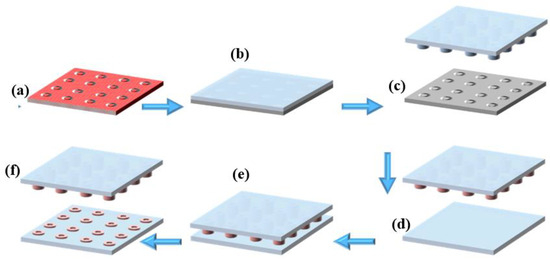
Figure 1.
Microcontact printing process: (a) silanized silicon mold, (b) casting of PDMS onto the silicon mold, (c) peeling off the cured PDMS to obtain the microstructured stamp, (d) inking of the PDMS stamp with fluorescent solution, (e) stamping process onto PDMS substrate, (f) removal of the PDMS stamp, leaving successfully transferred fluorescent microdonut patterns on the PDMS substrate.
2.4. PDMS Silanization with PFDTS
The PDMS substrate was activated using oxygen plasma (Diener Electronic PCCE Plasma-Surface-Technology, Ebhausen. Germany), which generated hydroxyl functional groups on the PDMS surface [36]. Subsequently, the activated PDMS was immersed in an ethanol solution containing 10 mM of PFDTS at 80 °C for 6 h. After the reaction, the substrate was gently rinsed with ethanol and dried under a stream of nitrogen. Finally, the PDMS substrate was placed in an oven at 90 °C for 1 h to complete the surface functionalization process.
2.5. Micro Contact Printing with Ink
Microcontact printing (µCP) was performed using a µCP machine from GeSiM (Germany), which is controlled by dedicated software to precisely manage the stamping parameters (Figures S2 and S3). The PDMS stamp was automatically fixed and lowered by the µCP printer head (full operating procedures are provided in the Supplementary Material). Before printing, the PDMS stamp bearing the microstructures was immersed in an ethanol-based ink solution containing an orange fluorescent marker (Figure 1d). The stamp was then inked for 5 min and dried under a stream of nitrogen. Next, the inked PDMS stamp was brought into conformal contact with the PFDTS silanized PDMS substrate (Figure 1e), and stamping was carried out for 20 s. After this period, the stamp was carefully removed (Figure 1f), leaving behind micro-patterned fluorescent circles on the PDMS substrate.
2.6. Micro Contact Printing with TSEUD
The PDMS substrate was activated by plasma/O2 treatment, generating hydroxyl functional groups on its surface (Figure 2a). The PDMS stamp was then inked with a 1% (v/v) solution of TESUD in ethanol for 10 min, followed by air drying. The µCP process (Figure 2b) was carried out carefully to avoid stamp collapse [34]. After printing onto the activated PDMS substrate, the assembly was placed in an oven at 90 °C for 1 h to promote silanization between TESUD and the silanol groups on the PDMS surface. At this stage, the PDMS substrate was successfully functionalized with printed TESUD self-assembled monolayers (SAMs) (Figure 2c).
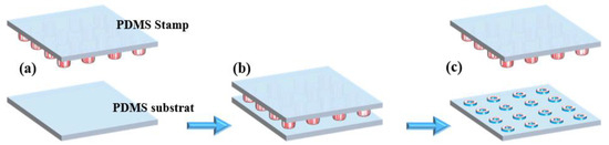
Figure 2.
µCP of TESUD: (a) inking of the PDMS stamp with TESUD solution, (b) stamping process onto the oxygen plasma-activated PDMS substrate, (c) removal of the PDMS stamp, leaving successfully TESUD transferred microdonut patterns on the PDMS substrate.
Generally, for silicon nitride, aluminum oxide, or hafnium dioxide substrates, we have previously reported µCP of TESUD or (3-Aminopropyl)triethoxysilane (APTES) silanes, using another silane as a blocking layer to prevent nonspecific adsorption [37,38,39]. However, in this study, the PDMS surface reverts to its hydrophobic state after 1 h at 90 °C in the oven. Therefore, there is no need to introduce an additional silane as a blocking layer. This was confirmed by the presence of large, homogeneous patterns of rhodamine-labeled antibodies without any nonspecific adsorption.
2.7. PDMS Biofunctionalization and TNF-α Detection
The biofunctionalization was carried out via an imination reaction between the aldehyde groups of the TESUD and the amine groups of the antibodies. The resulting imine bonds were then stabilized through reductive amination using sodium cyanoborohydride, converting them into stable secondary amines. This reaction enables the covalent attachment of the antibodies to the TESUD SAMs on the activated PDMS substrate (Figure 3a).
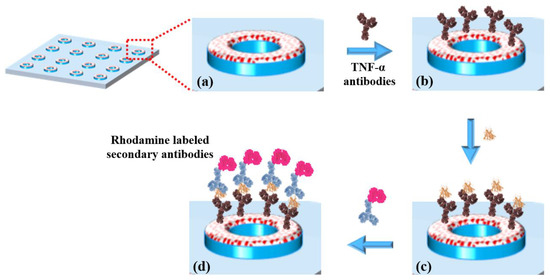
Figure 3.
(a) TESUD microdonut patterns; (b) immobilization of anti-TNF-α antibodies; (c) capture of TNF-α cytokines; (d) detection using rhodamine-labeled secondary antibodies, forming a sandwich complex: antibody–cytokine–rhodamine-labeled secondary antibody.
A solution containing 50 µg of anti-TNF-α antibodies in 1 mL of sodium tetraborate decahydrate buffer (pH = 9), supplemented with 4 mM sodium cyanoborohydride, was prepared. A volume of 0.5 mL of this solution was deposited onto the TESUD functionalized PDMS substrate and incubated for 30 min. The substrate was then rinsed with PBS buffer to remove unbound antibodies. At this stage, the biosensor consists of a PDMS substrate functionalized with circular patterns of immobilized anti-TNF-α antibodies.
2.8. Wettability
Surface wettability of the PDMS substrates was evaluated at each stage of chemical modification using contact angle measurements (Easydrop OCA 20, DataPhysics Instruments, Filderstadt, Germany). A 3 µL droplet of deionized water was gently deposited on the surface to assess the static contact angle. For each experimental condition, four independent measurements were taken per sample to ensure reproducibility and accuracy of the results.
2.9. Fluorescence Microscopy
Fluorescence images were acquired using a fluorescence microscope (Axio ZEISS, Baden-Württemberg, Germany) equipped with an HXP120C Kubler illumination system. Samples were observed under fluorescent light excitation: rhodamine was excited using a 550 ± 25 nm band pass filter, and the emitted fluorescence was collected through a 605 ± 70 nm band pass filter.
3. Results and Discussion
3.1. Micro Contact Printing µCP
As previously mentioned, the PDMS stamp was peeled off from the silicon master bearing microcircular structures on its surface. The microcontact printing (µCP) process was carried out using the µContact Printer (GeSIM, Bioinstruments and Microfluidics, Radeberg, Germany), controlled by the GeSIM software (µ-CP 3.0) (Figures S2–S4 in Supplementary Materials).
Prior to biofunctionalization, the µCP parameters were optimized using an orange fluorescent ink. Here, the µContact Printer is equipped with a printhead containing a PDMS membrane with replicated microstructures. The printhead was brought into conformal contact with the PDMS substrate surface, and the parameters, including pressure, contact time, and approach distance, were carefully adjusted (Figure 4a). High pressure combined with a short approach distance led to a phenomenon known as “roof collapse” (Figure 4b). In this case, the top surface (roof) of the PDMS stamp deforms and comes into contact with the substrate, resulting in both positive and negative features being transferred [34]. On the other hand, excessive pressure or too close an approach caused structural deformation, resulting in large, distorted circular patterns indicative of poor pattern fidelity (Figure 4c).
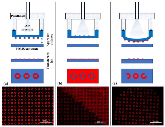
Figure 4.
Different µCP scenarios as a function of µContact Printer (GeSiM) parameter optimization: (a) homogeneous fluorescence image of µCP over a large area of micro donuts patterns using red ink, achieved under optimal conditions; (b) excessive air pressure and a short approach distance result in roof collapse; (c) insufficient air pressure combined with a large approach distance leads to incomplete contact, resulting in inhomogeneous µCP.
Once the optimal pressure and approach distance were defined, the stamping contact time was also optimized to minimize ink diffusion. As shown in Figure 5a,c, prolonged contact or excessive ink concentrations led to spreading of the ink on the PDMS substrate, causing spots or merged patterns instead of donuts. In fact, the ink diffusion into the PDMS bulk was consistently observed due to its porous nature.
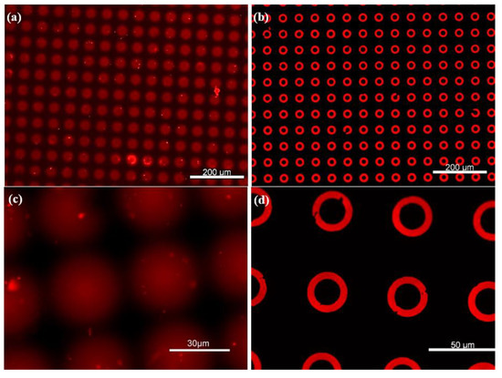
Figure 5.
Large area homogeneous µCP of microdonut patterns. (a,c) Non-silanized PDMS substrates, where the ink is absorbed into the surface, resulting in diffuse spot-like features. (b,d) PFDTS-silanized PDMS substrates, exhibiting highly well-defined microdonut structures due to the protective silane layer.
To prevent ink diffusion, the PDMS substrate was salinized with PFDTS as described previously and stamped again with the same donut microstructures. Table 1 shows the wettability parameters after each stage of PDMS chemical surface treatment. The contact angle measurement (CAM) decreased from 113.97° ± 1.24° to almost 0° after oxygen plasma treatment, which revealed a substantial increase in the hydrophilicity of the PDMS polymer films’ surface. This oxidation process facilitated the chemical functionalization with PFDTS. The latter was successfully immobilized onto the PDMS substrate, confirmed by the increase of CAM to 117.71° ± 1.2°. Here, only static wettability measurements were employed as a rapid and supportive tool to demonstrate successful chemical surface modification, serving as a preliminary step toward the detection process.

Table 1.
Contact angle measurements for bare PDMS, plasma/O2, and PFDTS-treated PDMS.
PDMS was silanized using PFDTS instead of OTS, as commonly employed for silicon surfaces, due to the incompatibility of OTS with PDMS. OTS is typically prepared in heptane, a solvent known to degrade the elastomeric PDMS matrix, whereas PFDTS is dissolved in ethanol, which preserves the structural integrity of the PDMS substrate.
After the silanization process, Figure 5b,d display well-defined donut-shaped microstructures, with no visible ink absorption into the PDMS substrate, owing to the protective PFDTS layer. This homogeneous stamping result was achieved by optimizing various parameters of the µCP GeSiM printer. Moreover, Figure 6 illustrates the high-fidelity reproduction of the donut patterns, from the silicon master to the PDMS stamp, and ultimately to the final stamped ink on the PFDTS silanized substrate.
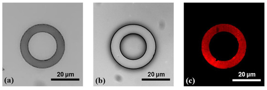
Figure 6.
Illustration of the stepwise reproduction of microdonut patterns via µCP (a) OTS-silanized silicon master mold; (b) PDMS stamp obtained by replica molding from the silicon master; (c) and donut-shaped ink patterns stamped onto a PFDTS silanized PDMS substrate using orange fluorescent ink.
The initial donut-shaped microstructures fabricated on the silicon mold exhibited inner and outer diameters of Ø int = 20 µm and Ø ext = 30 µm, respectively (Figure 6a). After replica molding with PDMS, the transferred structures on the stamp displayed slightly altered dimensions, with Ø int = 17.26 ± 0.12 µm and Ø ext = 30.57 ± 0.18 µm (Figure 6b). Following microcontact printing (µCP), the resulting features on the functionalized PDMS substrate measured Ø int = 19.56 ± 0.13 µm and Ø ext = 29.26 ± 0.14 µm, indicating a modest dimensional reduction compared to those on the PDMS stamp (Figure 6c). These variations are primarily due to the flexible nature of PDMS, which, owing to its low Young’s modulus [40], can undergo slight mechanical deformation during the stamping process. This elasticity may lead to minor stretching or compression of the printed patterns. Additionally, exposure to the inking solution may induce slight swelling of the PDMS, subtly altering the surface topology of the micro donuts. Such swelling can result in a gentle bulge or beveled edges of the microstructures, contributing to a decrease in the final printed feature size. These combined factors likely account for the minor size discrepancies observed between the microdonut structures on the PDMS stamp and those on the PFDTS silanized PDMS substrate.
3.2. Cytokines Detection
Anti-TNF-α antibodies were immobilized onto the activated TESUD patterned surfaces as previously described. To verify the successful immobilization of anti-TNF-α antibodies, the optical biosensor was incubated in a TNF-α cytokine solution (50 µg in 1 mL of PBS, pH 7.2) for 30 min. After a 30 sec rinse with PBS to remove unbound TNF-α cytokines, 0.5 mL of a rhodamine-labeled anti-TNF-α antibody solution was dropped onto the PDMS substrate. These secondary antibodies specifically recognize and bind TNF-α cytokines already captured by the immobilized surface antibodies, forming an anti-TNF-α < TNF-α > anti-TNF-α*rhodamine sandwich complex.
As shown in Figure 7a,b, well-defined circular patterns with strong fluorescence intensity were observed, confirming the presence of rhodamine-labeled secondary antibodies bound to the TNF-α cytokines. To rule out non-specific adsorption of rhodamine-labeled antibodies, a control experiment was performed under identical conditions but without prior incubation with TNF-α cytokines. In this case, no significant fluorescence was observed (Figure 7c), supporting the specificity of the detection. Upon enhancing the image contrast, faint microdonut patterns can be barely observed, likely due to residual PBS microcrystals adsorbed on the primary antibodies immobilized on the TESUD patterns (Figure 7d).
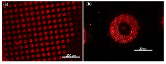
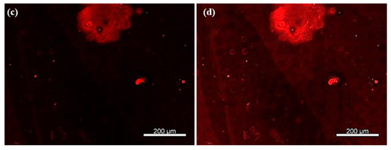
Figure 7.
Fluorescence images showing (a) more than 140 microdonuts exhibiting fluorescence from rhodamine-labeled anti-TNF-α antibodies immobilized on the patterns, confirming both the reproducible detection of TNF-α cytokines and the effective immobilization of the primary anti-TNF-α antibodies; (b) magnification of the positive pattern showing specific detection by the immobilized antibodies anti-TNF-α; (c) no fluorescent signal was observed for the negative control, confirming the specificity of the detection; and (d) after enhancing the image contrast of the negative test, faint microdonut patterns can be barely distinguished, likely due to residual PBS microcrystals adsorbed on the surface.
4. Conclusions
In this study, we successfully developed a fluorescence-based optical biosensor for the detection of TNF-α cytokines using microcontact printing (µCP) on PDMS substrates. The optimization of µCP parameters, such as applied air pressure and the approach distance of the GeSiM µCP printer, enabled the homogeneous transfer of well-defined microdonut patterns over large areas. The silanization of PDMS with PFDTS proved essential for pattern fidelity, unlike non-silanized PDMS, which absorbs the ink and results in diffuse spot-like features. The immobilization of anti-TNF-α antibodies on TESUD-functionalized patterns was demonstrated using a sandwich immunoassay involving rhodamine-labeled secondary anti-TNF-α antibodies. A strong fluorescent signal in the presence of TNF-α and its absence in control experiments confirmed the specificity of the biosensor.
A major focus of this work was the microengineering of the surface biofunctionalization process using soft lithography and µCP techniques. The fabrication of PDMS-based stamps and the successful optimization of printing parameters effectively resolved the issue of ink absorption, ensuring reproducible and localized functionalization. To demonstrate proof-of-concept, a single concentration of TNF-α (50 µg/mL) and a fixed concentration of rhodamine-labeled secondary antibody were used in preliminary testing.
While the present study demonstrates proof-of-concept detection and reproducible surface patterning, the biosensor has not yet been validated at clinically relevant TNF-α concentrations, nor has it been evaluated for long-term stability, multiplexing capability, or compared quantitatively with established clinical assays. Addressing these aspects will be the focus of future work for the quantitative detection of biomarkers by exploring a range of cytokine concentrations to determine the biosensor’s sensitivity, limit of detection (LOD), and dynamic range. In addition, the effect of varying the concentration of rhodamine-labeled secondary antibodies will be investigated to optimize fluorescence intensity and minimize background signal. This work lays a solid foundation for developing robust, PDMS-based biosensing platforms for inflammatory biomarkers using µCP techniques.
Supplementary Materials
The following supporting information can be downloaded at: https://www.mdpi.com/article/10.3390/chemosensors13090338/s1, Figure S1: (a) Injection of the PDMS prepolymer onto the backing substrate that will be in contact with the aluminum holder; (b) Placement of the silicon mold onto the aluminum holder; (c) Fixing the PDMS support onto the aluminum holder; (d) Injection of PDMS to fabricate the PDMS membrane bearing the microstructures of the silicon mold. Figure S2: The µCP machine, equipped with a UV lamp for nanoimprint lithography, and monitored by GeSiM software. Figure S3: The printhead of the µCP equipment automatically picks up and places the PDMS membrane at the stamping position for microcontact printing, using software-defined parameters to control membrane pickup and release, air pressure, approach distance, and stamping duration. Figure S4: Schematic illustration of the µCP procedure: the printhead rapidly approaches the predefined pre-stamping position, then moves slowly toward the substrate to ensure a large, homogeneous stamped surface.
Author Contributions
Writing—original draft preparation, editing, formal analysis, methodology, and validation, A.B. (Abdoullatif Baraket), A.B. (Alexi Bonament) and A.A.; writing, editing, formal analysis, and validation, A.B. (Abdoullatif Baraket), H.N. and M.B.; formal analysis and supervision, N.J.-R. and A.E.; transducer fabrication, J.B.; review, editing, and supervision, A.E. and N.Z. All authors have read and agreed to the published version of the manuscript.
Funding
The authors gratefully acknowledge the financial support provided by the European project GREENSMARTMED (Euro_MED0200399) and the PHC PROCOPE program (49540WG).
Institutional Review Board Statement
Not applicable.
Informed Consent Statement
Not applicable.
Data Availability Statement
The data that support the findings of this study are available from the corresponding author upon reasonable request.
Conflicts of Interest
The authors declare no conflicts of interest.
References
- Savarese, G.; Becher, P.M.; Lund, L.H.; Seferovic, P.; Rosano, G.M.C.; Coats, A.J.S. Global Burden of Heart Failure: A Comprehensive and Updated Review of Epidemiology. Cardiovasc. Res. 2023, 118, 3272–3287. [Google Scholar] [CrossRef]
- Bekele, F.; Sheleme, T.; Tsegaye, T.; Parameswari, S.A.; Syed, M.A.; Tafese, L.; Gezimu, W. Prevalence and risk factors of mortality among heart failure patients in low resource setting hospitals: A multicenter prospective observational study. Front. Cardiovasc. Med. 2024, 11, 1429513. [Google Scholar] [CrossRef]
- McDonagh, T.A.; Metra, M.; Adamo, M.; Gardner, R.S.; Baumbach, A.; Böhm, M.; Burri, H.; Butler, J.; Čelutkienė, J.; Chioncel, O.; et al. 2021 ESC Guidelines for the Diagnosis and Treatment of Acute and Chronic Heart Failure. Eur. Heart J. 2021, 42, 3599–3726. [Google Scholar] [CrossRef]
- Nadar, S.K.; Shaikh, M.M. Biomarkers in Routine Heart Failure Clinical Care. Card. Fail. Rev. 2019, 5, 50–56. [Google Scholar] [CrossRef]
- Licordari, R.; Correale, M.; Bonanno, S.; Beltrami, M.; Ciccarelli, M.; Micari, A.; Palazzuoli, A.; Dattilo, G. Beyond Natriuretic Peptides: Unveiling the Power of Emerging Biomarkers in Heart Failure. Biomolecules 2024, 14, 309. [Google Scholar] [CrossRef]
- Biasucci, L.M.; Maino, A.; Grimaldi, M.C.; Cappannoli, L.; Aspromonte, N. Novel Biomarkers in Heart Failure: New Insight in Pathophys-iology and Clinical Perspective. J. Clin. Med. 2021, 10, 2771. [Google Scholar] [CrossRef]
- Carris, N.W.; Mhaskar, R.; Coughlin, E.; Bracey, E.; Tipparaju, S.M.; Halade, G.V. Novel Biomarkers of Inflammation in Heart Failure with Preserved Ejection Fraction: Analysis from a Large Prospective Cohort Study. BMC Cardiovasc. Disord. 2022, 22, 221. [Google Scholar] [CrossRef]
- Jaric, S.; Kudriavtseva, A.; Nekrasov, N.; Orlov, A.V.; Komarov, I.A.; Barsukov, L.A.; Gadjanski, I.; Nikitin, P.I.; Bobrinetskiy, I. Femtomolar Detection of the Heart Failure Bi-omarker NT-proBNP in Artificial Saliva Using an Immersible Liquid-Gated Aptasensor with Reduced Graphene Oxide. arXiv 2023, arXiv:2307.16692. [Google Scholar] [CrossRef]
- Nunes, L.A.S.; Mussavira, S.; Bindhu, O.S. Clinical and Diagnostic Utility of Saliva as a Non-Invasive Diagnostic Fluid: A Systematic Review. Biochem. Med. 2015, 25, 177–192. [Google Scholar] [CrossRef]
- Bahbah, E.I.; Noehammer, C.; Pulverer, W.; Jung, M.; Weinhaeusel, A. Salivary biomarkers in cardiovascular disease: An insight into the current evidence. FEBS J. 2021, 288, 6392–6405. [Google Scholar] [CrossRef]
- Klimiuk, A.; Zalewska, A.; Knapp, M.; Skutnik-Radziszewska, A.; Maciejczyk, M. Could Inflammation Contribute to Salivary Gland Dysfunction in Patients with Chronic Heart Failure? Front. Immunol. 2022, 13, 1005981. [Google Scholar] [CrossRef]
- Rammos, A.; Bechlioulis, A.; Kalogeras, P.; Tripoliti, E.E.; Goletsis, Y.; Kalivi, A.; Blathra, E.; Salvo, P.; Trivella, M.G.; Lomonaco, T.; et al. Salivary Biomarkers for Diagnosis and Therapy Monitoring in Patients with Heart Failure. A Systematic Review. Diagnostics 2021, 11, 824. [Google Scholar] [CrossRef]
- Assareh, A.; Haybar, H.; Yoosefi, H.; Bozorgmanesh, M. Bedside-Friendly Prediction for Presence of Post-Myocardial Infarction Systolic Dysfunction Using Multimarker Panel: Integrating Salivary Diagnostics into Clinical Practice. Korean Circ. J. 2013, 43, 246–254. [Google Scholar] [CrossRef] [PubMed][Green Version]
- Dekker, R.L.; Lennie, T.A.; Moser, D.K.; Miller, C.S.; Ebersole, J.L.; Chung, M.L.; Campbell, C.L.; Bailey, A.; Tovar, E.G. Salivary Biomarkers, Oral Inflammation, and Functional Status in Patients with Heart Failure. Biol. Res. Nurs. 2017, 19, 153–161. [Google Scholar] [CrossRef] [PubMed]
- Lequin, R.M. Enzyme Immunoassay (EIA)/Enzyme-Linked Immunosorbent Assay (ELISA). Clin. Chem. 2005, 51, 2415–2418. [Google Scholar] [CrossRef] [PubMed]
- Khozeymeh, F.; Mortazavi, M.; Khalighinejad, N.; Akhavankhaleghi, M. Salivary Levels of Interleukin-6 and Tumor Necrosis Factor-α in Patients Undergoing Hemodialysis. Dent. Res. J. 2016, 13, 69–73. [Google Scholar] [CrossRef]
- Lu, Y.; Zhou, Q.; Xu, L. Non-Invasive Electrochemical Biosensors for TNF-α Cytokines Detection in Body Fluids. Front. Bioeng. Biotechnol. 2021, 9, 701045. [Google Scholar] [CrossRef]
- Aydın, S.; Emre, E.; Uğur, K.; Aydın, M.A.; Şahin, İ.; Çınar, V.; Akbulut, T. An over-view of ELISA: A review and update on best laboratory practices for quantifying peptides and proteins in biological fluids. J. Int. Med. Res. 2025, 53, 3000605251315913. [Google Scholar] [CrossRef]
- Baraket, A.; Ghedir, E.K.; Zine, N.; Jaffrezic Renault, N.; Aarfane, A.; Nasrellah, H.; Bel-hora, F.; Bonet, F.P.; Bausells, J.; Errachid, A. Electrochemical Immunosensor Prototype for N Terminal Natriuretic Peptide Detection in Human Saliva: Heart Failure Biomedical Application. Chemosensors 2025, 13, 66. [Google Scholar] [CrossRef]
- Baraket, A.; Lee, M.; Zine, N.; Caruso, R.; Trivella, M.G.; Errachid, A. Electrochemical Biosensor for Interleukin 10 Detection in Real Human Plasma: Heart Failure Biomedical Application. Int. J. Cardiovasc. Res. 2017, 6, 1. [Google Scholar] [CrossRef]
- Baraket, A.; Lee, M.; Zine, N.; Sigaud, M.; Bausells, J.; Errachid, A. A Fully Integrated Electrochemical Biosensor Platform Fabrication Process for Cytokine Detection. Biosens. Bioelectron. 2017, 93, 170–175. [Google Scholar] [CrossRef] [PubMed]
- Barhoumi, L.; Bellagambi, F.G.; Vivaldi, F.M.; Baraket, A.; Clément, Y.; Zine, N.; Ben Ali, M.; Elaissari, A.; Errachid, A. Ultrasensitive Immunosensor Array for TNF-α Detec-tion in Artificial Saliva Using Polymer Coated Magnetic Microparticles onto Screen Print-ed Gold Electrode. Sensors 2019, 19, 692. [Google Scholar] [CrossRef]
- Bellagambi, F.G.; Baraket, A.; Longo, A.; Vatteroni, M.; Zine, N.; Bausells, J.; Fuoco, R.; Di Francesco, F.; Salvo, P.; Karanasiou, G.S.; et al. Electrochemical Biosensor Platform for TNF-α Cytokine Detection in Both Artificial and Human Saliva: Heart Failure. Sens. Actuators B Chem. 2017, 251, 1026–1033. [Google Scholar] [CrossRef]
- Ghedir, E.K.; Baraket, A.; Benounis, M.; Zine, N.; Errachid, A. Electrochemical Multi-plexed N Terminal Natriuretic Peptide and Cortisol Detection in Human Artificial Saliva: Heart Failure Biomedical Application. Chemosensors 2023, 11, 416. [Google Scholar] [CrossRef]
- Baraket, A.; Lee, M.; Zine, N.; Yaakoubi, N.; Bausells, J.; Errachid, A. A Flexible Electrochemical Micro Lab on Chip: Ap-plication to the Detection of Interleukin 10. Microchim. Acta 2016, 183, 2155–2162. [Google Scholar] [CrossRef]
- Homola, J. Surface Plasmon Resonance Sensors for Detection of Chemical and Biological Species. Chem. Rev. 2008, 108, 462–493. [Google Scholar] [CrossRef]
- Lohcharoenkal, W.; Abbas, Z.; Rojanasakul, Y. Advances in Nanotechnology-Based Biosensing of Immunoregulatory Cytokines. Biosensors 2021, 11, 364. [Google Scholar] [CrossRef]
- Damborský, P.; Švitel, J.; Katrlík, J. Optical Biosensors. Essays Biochem. 2016, 60, 91–100. [Google Scholar] [CrossRef]
- Mostufa, S.; Rezaei, B.; Ciannella, S.; Yari, P.; Gómez-Pastora, J.; He, R.; Wu, K. Advancements and Perspectives in Optical Biosensors. ACS Omega 2024, 9, 24181–24202. [Google Scholar] [CrossRef]
- Xia, Y.; Whitesides, G.M. Soft Lithography. Angew. Chem. Int. Ed. 1998, 37, 550–575. [Google Scholar] [CrossRef]
- Qin, D.; Xia, Y.; Whitesides, G.M. Soft Lithography for Micro- and Nanoscale Patterning. Nat. Protoc. 2010, 5, 491–502. [Google Scholar] [CrossRef]
- Bernard, A.; Delamarche, E.; Schmid, H.; Michel, B.; Biebuyck, H. Printing Patterns of Proteins. Langmuir 2000, 14, 2225–2229. [Google Scholar] [CrossRef]
- Delamarche, E.; Bernard, A.; Schmid, H.; Michel, B.; Biebuyck, H. Patterned Delivery of Immunoglobulins to Surfaces Using Microfluidic Networks. Science 1997, 276, 779–781. [Google Scholar] [CrossRef]
- Baraket, A.; Lee, M.; Zine, N.; Sigaud, M.; Yaakoubi, N.; Trivella, M.G.; Zabalad, M.; Bausells, J.; Jaffrezic Renault, N.; Errachid, A. Diazonium Modified Gold Microelec-trodes onto Polyimide Substrates for Impedimetric Cytokine Detection with an Integrated Ag/AgCl Reference Electrode. Sens. Actuators B Chem. 2013, 189, 165–172. [Google Scholar] [CrossRef]
- Lee, M.; Lopez-Martinez, M.J.; Baraket, A.; Zine, N.; Errachid, A.; Jaffrezic-Renault, N.; Bausells, J. Combination of PDMS Microfilters and Micromixers Based on Flexible Thermoplastic Films for Size Sorting and Mixing of Microparticles. J. Appl. Polym. Sci. 2015, 132, 42088. [Google Scholar] [CrossRef]
- Baraket, A.; Zine, N.; Lee, M.; Bausells, J.; Jaffrezic-Renault, N.; Bessueille, F.; Yaakoubi, N.; Errachid, A. Development of a Flexible Microfluidic System Based on a Simple and Reproducible Sealing Process between Polymers and Poly(dimethylsiloxane). Microelectron. Eng. 2013, 110, 173–177. [Google Scholar] [CrossRef]
- Lee, M.; Baraket, A.; Zine, N.; Zabala, M.; Campabadal, F.; Caruso, R.; Trivella, M.G.; Jaffrezic-Renault, N.; Errachid, A. A novel three-dimensional biosensor based on aluminum oxide: Application for early-stage detection of human interleukin-10. Methods Mol. Biol. 2014, 1172, 49–64. [Google Scholar]
- Bougrini, M.; Baraket, A.; Jamshaid, T.; El Aissari, A.; Bausells, J.; Zabala, M.; El Bari, N.; Bouchikhi, B.; Jaffrezic-Renault, N.; Abdelhamid, E.; et al. Development of a novel capacitance electrochemical biosensor based on silicon nitride for ochratoxin A detection. Sens. Actuators B Chem. 2016, 234, 446–452. [Google Scholar] [CrossRef]
- Lee, M.; Zine, N.; Baraket, A.; Zabala, M.; Campabadal, F.; Caruso, R.; Trivella, M.G.; Jaffrezic-Renault, N.; Errachid, A. A novel biosensor based on hafnium oxide: Application for early stage detection of human interleukin-10. Sens. Actuators B Chem. 2012, 175, 201–207. [Google Scholar] [CrossRef]
- Fuard, D.; Tzvetkova-Chevolleau, T.; Decossas, S.; Tracqui, P.; Schiavone, P. Optimiza-tion of Poly(dimethylsiloxane) (PDMS) Substrates for Studying Cellular Adhesion and Motility. Microelectron. Eng. 2008, 85, 1289–1293. [Google Scholar] [CrossRef]


Disclaimer/Publisher’s Note: The statements, opinions and data contained in all publications are solely those of the individual author(s) and contributor(s) and not of MDPI and/or the editor(s). MDPI and/or the editor(s) disclaim responsibility for any injury to people or property resulting from any ideas, methods, instructions or products referred to in the content. |
© 2025 by the authors. Licensee MDPI, Basel, Switzerland. This article is an open access article distributed under the terms and conditions of the Creative Commons Attribution (CC BY) license (https://creativecommons.org/licenses/by/4.0/).