Abstract
The formation of scale in hot springs and geothermal brines can be detected quickly and easily using optical fiber-based scale sensors. This paper describes the development of a portable sensor for the in situ detection of scale in geothermal water. This sensor was used to detect the formation of calcium carbonate and silica scale and to assess the effectiveness of their inhibitors. The performance of the sensor was evaluated using calcium carbonate scale. In laboratory experiments using both the newly developed sensor and a conventional nonportable sensor, the strength of the transmitted signal was found to decrease significantly as the amount of scale increased. It was considered that this sensor can accurately evaluate only scale formation without being affected by turbidity. The scale that was deposited on each material (optical fiber core, glass plate, polyvinyl chloride (PVC), and SUS304) was observed using a shape analysis laser microscope. Based on these observations, we concluded that this sensor could be used to predict the amount of scale deposited in real time. In situ evaluation of the sensor was conducted at a blowout carbonated hot spring on Rishiri Island, which is located off the coast of Hokkaido, Japan. The results obtained from experiments using hot spring water showed a similar sensor response within a comparable time range as those obtained from the laboratory experiments. The results of this study thus demonstrate that this novel portable scale sensor is suitable for use in geothermal power plants and investigating effectiveness of inhibiters under different conditions.
1. Introduction
In many countries, thermal power stations supply most of the electricity used [1]. However, these power stations emit large amounts of greenhouse gases, which contribute to global warming [2,3]. There is, therefore, an urgent need to develop power generation based on renewable sources [4]. Japan is promoting the development of renewable energy and has the goal of raising the share of electricity produced from renewable sources to around 30% by 2030. As part of this transition, Japan intends to promote the development of its geothermal resources, which are the third most abundant in the world. Geothermal resources have been used as a stable energy source for many years, especially in regions where they are abundant [5]. The properties and chemical composition of thermal water are sensitive to changes in temperature, pressure, and pH, and the efficiency of processes that utilize thermal water are affected by the precipitation of inorganic salts, which are collectively known as geothermal scale [6]. Since solubility and activity coefficients at extreme conditions are unknown, scaling is largely unpredictable. The formation of scale leads to problems such as equipment failure, blocked pipes, and a reduction in the efficiency of heat exchange [7,8]. For this reason, the inhibition and prevention of scale formation has been studied for many years, and various methods of inhibiting and preventing scale, such as the addition of scale inhibitors, pH adjustment, and the use of ultrasound, have been investigated and implemented [9,10,11,12,13,14,15].
To examine the effectiveness of scale inhibitors and other suppression methods under various conditions, it is necessary to monitor the formation of scale in real time. The methods used to do this should be simple to implement and produce results quickly. Visual observations have long been used to monitor the formation of scale in geothermal fluids. However, it is difficult to make these observations in an operational setting. Other methods involve determining the amount of scale deposition by using an experimental device that imitates real pipes or by immersing a test object, such as a piece of metal, in hot water and measuring the change in mass [10,16,17]. These methods have many disadvantages, including cost and complexity, and it is difficult to evaluate the results obtained within a short time. There is, therefore, a need to develop simpler methods of monitoring the generation of scale in geothermal water that can be applied in real time.
Optical fiber sensors use passive optical components to reflect or transmit light from light sources and to convert information into optical signals. This means that they can be used for the acquisition of data at distances of several tens of kilometers. The advantages of optical fiber sensors include their relatively low cost (depending on the type of optical fiber); in addition, no power supply is required for the sensing unit; real-time, remote multipoint measurements can be obtained; and the sensors are easy to handle [18]. As optical waveguides, fiber optics enable less common interrogation methods, in particular, evanescent wave spectroscopy and spatially resolved spectroscopy. Therefore, the use of fiber optic sensors with a variety of detection principles has been actively researched in various areas of analytical sciences, and many review articles have been published [19,20,21,22,23,24,25,26,27].
The development for use of sensors based on mass-produced optical fibers has become widespread. Optical fiber sensors that make use of evanescent waves are generally constructed so that the core is exposed to allow for it to be used as the sensing area. The critical angle of the fiber depends on the refractive index of the surrounding medium; as the refractive index changes, the intensity of the light that emerges from the core changes (as the extent to which the evanescent light waves are absorbed varies). The use of optical fiber sensors based on evanescent waves generated at the exposed core has been widely reported including in studies in which biosensors and chemical sensors were used, such as a sensor based on localized surface plasmon resonance [28], 4-nitrophenol sensor [29], H2O2 biosensor [30], mercury sensor [31], sensor for soil testing [32], etc. We also reported on a biofilm sensor [33] and spectroelectrochemical sensors [34,35] using mass-produced unclad optical fibers.
Optical fibers are also resistant to heat and pressure, which makes them very suitable for use in geothermal fluids, where the temperature and pressure can be extremely high. Previously, we developed an optical fiber sensor that can be used to monitor the formation of scale in geothermal fluids and for which results can be obtained within a few hours [36,37,38,39,40,41]. A schematic diagram illustrating the principle and an example of how this sensor responds is shown in Figure 1. When scale that has a higher refractive index than the core of fiber optic forms on the surface of the sensor, total internal reflection at this surface is inhibited. As a result, the intensity of the light that reaches the detector is reduced and the amount of scale formation can be determined. We already have reported on a method for monitoring calcium carbonate [37,41] and silica scale precipitated from geothermal water and its vapor [39] that uses this sensor. In addition, we evaluated the effectiveness of using electromagnetic waves and scale inhibitors to inhibit the formation of calcium carbonate scale [40]. These sensors have to be replaced when a certain amount of scale forms at the sensing portion. The use of a fiber covered with a platinum mesh allows for the sensor to be regenerated for multiple measurements by dissolving the scale precipitated on the fiber surface as a result of the pH changes associated with the anodic electrolysis of water [38]. Real-time monitoring of barite deposition using a fiber optic sensor under high pressure and high temperature conditions in autoclaves has also been reported by Zotzmann et al. [42]. The monitoring system using fiber optic overcomes a major drawback of existing non-optical detection.
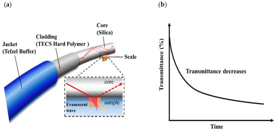
Figure 1.
Principle of scale sensor based on an optical fiber: (a) scale detection based on evanescent waves and (b) graph illustrating change in transmittance due to the precipitation of scale.
In this study, we developed a portable fiber optic scale sensor that can be used for in-situ measurements. The responses to the formation of different types of scale obtained using the portable sensor was compared with those obtained using conventional sensors. We also evaluated images of the calcium carbonate scale deposited on the surfaces of various materials (SUS304, polyvinyl chloride (PVC), and glass slides) on which calcium carbonate scale formed. The amount of scale that actually adhered to the equipment was calculated based on the mass of the scale attached to each type of material and the response of the sensor. Finally, in situ evaluation of the sensor was conducted at a hot spring and at a geothermal power plant.
2. Materials and Methods
2.1. Chemical Reagents and Materials
Sodium hydrogen carbonate, calcium chloride dihydrate, sodium sulfate, barium chloride dihydrate, acetone, ethanol, and kaolin were purchased from Wako Pure Chemicals Industries, Ltd (Osaka, Japan). All reagents were of analytical grade, and solutions of these compounds were prepared by distilled water.
A step index multimode optical fiber (FT200EMT; Thorlabs, Newton, NJ, USA) that had a silica core with a 200 μm diameter and a refractive index of 1.459 (589.3 nm) was used. The cladding was made of TECS hard polymer cladding with a refractive index of 1.398 (589.3 nm); Tefzel buffer was used as the protective film. Since the optical and mechanical properties of fused silica are stable up to about 1000 °C, it is very suitable for use under high-temperature, high-pressure conditions, such as in geothermal fluids. Before any measurements were made, the jacket around the central part of the optical fiber was removed; the cladding was also removed by rubbing it with a solvent-resistant wipe (pro-wipe) soaked in acetone.
In the conventional sensor, a halogen light source (HL-2000-FHSA-LL; Ocean Optics, Orlando, FL, USA) and a spectrophotometer (MV-3200; Jasco, Tokyo, Japan) were connected by an optical fiber sensor. A shape analysis laser microscope (VK-X1000 series; Keyence Corporation, Itasca, IL, USA) was used to observe the scale that formed on various test materials. An ion coater (JFC-1500; JEOL, Tokyo, Japan) was used to deposit gold film on these materials before the observations were made. The test pieces were weighed using an analytical balance (AG285; Mettler Toledo, Greifensee, Switzerland).
2.2. Portable Sensor
The device consists of two LED light sources (560 nm and 832 nm), two photodetectors, and a touch panel PC (Figure S1). The device has a two-channel sensor. The sensor is compact and has dimensions of 24 × 16 × 5.5 cm3 (Figure S2a). The sensor can be fabricated inexpensively using mass-produced optoelectronic components. In addition, the software can determine the change in transmittance with time and save the measurement data in CSV format.
2.3. Method for Determining the Amount of Scale
Both the portable sensor and a conventional sensor were used in this study. The length of sensing area was set as 5 cm in all the laboratory tests. The sensitivity of the scale sensor can be controlled with the length of the sensing area [41]. In the field tests, the length of the area that was monitored was fixed as 10 cm because the amount of scale deposition was smaller than in the laboratory tests. A newly fabricated optical fiber sensor was used for each measurement.
An optical fiber sensor was directly inserted into a U-shaped stainless-steel tube (which had a bending radius of approximately 1 cm); the upper part of the tube was used as the sensor in the subsequent measurements. To prevent the fiber optic sensor from moving, the end of the U-tube and the fiber optic were fixed using a rubber tube. In both the portable and nonportable sensors, a connector was used to connect one end of the sensor to the light source and the other end to the detector as shown in Figure 2. In the laboratory, we confirmed that this measurement system had the same sensitivity as our previous method [41] (Figure S2b). Transmittance measurements were performed indoors at room temperature and atmospheric pressure using both the portable and nonportable sensors.
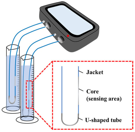
Figure 2.
U-shaped scale sensor arrangement.
2.4. Observations of Scale Deposition on Different Surfaces and Calculation of Scale Coverage
Observations of the formation of scale on various test pieces were carried out. An optical fiber and various test pieces were immersed in the measurement solution (100 mM CaCO3 solution; saturation index (SI) of calcite: 1.77) with or without kaolin. The test pieces were removed after 15, 30, 60, 120, and 300 min, washed with ethanol, and dried in air. After that, they were measured using a shape analysis laser microscope in laser confocal mode with an objective lens magnification of ×50. The amount of scale covering the surface of each test piece was binarized with respect to a specific threshold value using ImageJ. The scale coverage was then determined from the binarized area within a fixed area (300 × 300 pixels).
Determination of the Scale Mass
Each time the test pieces were removed from the test solution, they were washed and dried as described above and then weighed using an electronic balance. In each case, the sample was weighed three times, and the average mass was calculated.
2.5. Monitoring the Scale Formation under High-Temperature and High-Pressure Conditions
The experiments were carried out in a high-temperature, high-pressure stainless-steel vessel with the set of scale sensor. The reaction vessel containing the test solutions (5 mM NaHCO3 and CaCl2) was wrapped and heated with a tape heater. The reaction vessel was covered with heat insulating material and the temperature of the reaction vessel was monitored throughout the experiment.
2.6. Field Tests
A field experiments was conducted at the Rishiri Fureai hot spring on Rishiri Island, Hokkaido and at the Onuma geothermal power plant (O-12R), which is located in the city of Kazuno, Akita Prefecture. The hot spring water was pumped from the spring with a hose, placed in the bathtub and overflowed at a constant flow rate to prevent the temperature of the hot spring water in the bathtub from changing [36].
3. Results and Discussion
3.1. Performance of the Portable Scale Sensor and Comparison of Its Sensitivity with That of a Nonportable Sensor
The responses of the portable and nonportable (conventional) scale sensors to the formation of CaCO3, calcium sulfate (CaSO4), and barium sulfate (BaSO4) scale were compared. These types of scale have been reported to precipitate in both geothermal and oil field facilities.
First, we compared the sensitivity of the two sensors using calcium carbonate as a test compound. An optical fiber sensor was immersed in a solution produced by mixing equal volumes of 100 mM NaHCO3 and CaCl2 (saturation index (SI) of calcite: 1.77). Figure 3 shows the transmittance that was then measured using the two sensors based on the same detection principle. The results for the portable sensor show a rapid decrease in transmittance in both the visible and near-infrared wavelengths as the CaCO3 forms; no dependence of the transmittance on the wavelength was observed (Figure 3a). A similar response was observed using the nonportable sensor: the transmittance decreased by about 80% (Figure 3b,c). An expression approximating the response of the sensors showed that the initial response rate (at 0–120 min) was 0.49%/min and 0.45%/min at 560 nm and 832 nm, respectively, for the portable sensor and 0.54%/min and 0.51%/min, respectively, for the nonportable sensor. The intersection of the curve described by this expression (0–120 min) and the slope (240–300 min) was used to determine the saturation time. The saturation times were calculated as 145 min (560 nm) and 155 min (832 nm) for the portable sensor and 117 min (560 nm) and 115 min (832 nm) for the nonportable sensor. Although there was a slight difference in the response immediately after the start of the experiment, these results suggest that the portable sensor could be used to monitor scale generation with the same degree of sensitivity as the nonportable sensor.
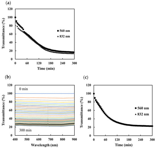
Figure 3.
Transmittance measured by the scale sensors during the precipitation of calcium carbonate: (a) change in transmittance at 560 nm (■) and 832 nm (▲) measured using the portable sensor, (b) change in the transmittance spectrum measured using the nonportable sensor, and (c) change in transmittance with time at 560 nm (■) and 832 nm (▲).
Similar experiments were then conducted to evaluate the response of the sensors to the formation of BaSO4 and CaSO4. The concentration of the solutions was set so that the turbidity matched the maximum turbidity of the CaCO3 solution. The sensors were immersed in a solution produced by mixing equal volumes of 2.5 mM BaCl2 and Na2SO4 (SI of barite: 4.29) and 150 mM CaCl2 and Na2SO4 (SI of anhydrite: 0.92). The transmittances measured by each sensor during the formation of BaSO4 scale are shown in Figure 4a–c. It can be seen that immediately after the start of the measurements, the transmittance of both sensors decreases by about 60%.
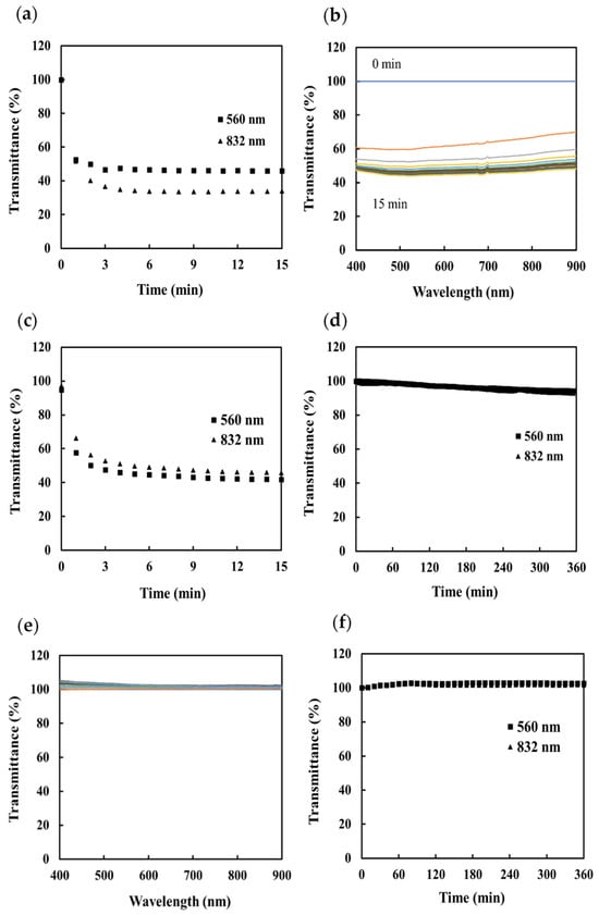
Figure 4.
Transmittance measured by the scale sensors during the precipitation of BaSO4 scale: (a) change in transmittance with time measured using the portable sensor, (b) transmission spectrum measured using the nonportable sensor, and (c) change in transmittance with time measured using the nonportable sensor. Transmittance measured by the scale sensors during the precipitation of CaSO4: (d) change in transmittance with time measured using the portable sensor, (e) transmission spectrum measured using the nonportable sensor, and (f) change in transmittance with time measured using the nonportable sensor transmittance then saturates at about 40%.
The initial response rate and the saturation time were measured at 560 nm and 832 nm. The initial response rates were 25.0%/min and 29.9%/min, respectively, for the portable sensor and 23.5%/min and 21.0%/min, respectively, for the nonportable sensor. The saturation time was 2 min for all measurements, which is a very fast response compared to that for CaCO3. We consider that this is because the saturation index of the BaSO4 was very large and the BaSO4 scale grew very quickly. The transmittance measurements made during the formation of the CaSO4 scale are shown in Figure 4d–f. For both the portable and nonportable sensor, no change in the transmittance due to scale formation can be observed after 360 min. Observations also showed that no scale formation was visible on the silica core, which is the sensing part, but a large amount of scale was visible on the jacket (Figure S3). We consider that this is because a highly homogeneous substrate surface, such as the silica core, does not provide nuclei suitable for scale growth; thus, scale formation did not occur. More sensitive measurements could be made in the future if suitable core materials were used for each scale type.
3.2. Effect of Turbidity on Scale-Formation Measurements
To evaluate the effect of solution turbidity on the scale-formation measurements, the transmittance response of sensor was also measured in turbid solutions. A cloudy solution was prepared using kaolin. The sensing portion of scale sensor connected with portable sensor was then immersed in 3 L of water. After 5 min, a kaolin solution with a concentration of 200 mg/L was added at a rate of 20 mL/min using a peristaltic pump. The transmittance of this solution and that of a 100 mM CaCO3 solution mixed with a 100 mg/L kaolin solution are shown in Figure 5a. Only a slight decrease in the transmittance can be observed as the turbidity of the kaolin solution increases. In contrast, the CaCO3 solution shows a significant decrease in transmittance due to scale formation even though the solution itself was turbid. The response saturation times were calculated to be 124 min (560 nm) and 127 min (832 nm), indicating that scale formation can be accurately measured even in the case of turbid solutions such as kaolin. The transmittance response of the sensor was measured at 5, 10, 15, 30, 60, 90 and 120 min after preparation of the 100 mM CaCO3 solution. The solutions became increasingly turbid with time, reaching a maximum at approximately 15 minutes after solution preparation. Figure 5b shows the measured transmittance; it reduced by only a few percent even after a total of seven immersions. These results suggest that this sensor can be evaluated only for the scale formation on its surface, without being affected by the turbidity of the solution. This is because the sensor detects the evanescent waves that seep out from the interface where total internal reflection occurs.
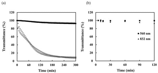
Figure 5.
Transmittance response of the sensor for turbid solutions: (a) transmittance response of sensor in kaolin solution added to pure water at 560 nm (■) and 832 nm (▲) and of CaCO3 scale precipitated in kaolin solution at 560 nm (□) and 832 nm (△) and (b) transmittance measured by portable sensor immersed in CaCO3 solution.
The penetration depth of the evanescent wave is given by the following formula:
Here, λ is the light wavelength, n1 and n2 are the refractive indices of the core and sample, respectively, and θ is the incidence angle. The distance traveled by evanescent waves in this sensor, as calculated using this equation, is in the order of tens to hundreds of nanometers. In this sensor, total internal reflection occurs several times within the sensing area due to the use of a multimode optical fiber. Therefore, 10 μM rhodamine B, a kind of xanthine dye that has a maximum absorption around 555 nm (molar absorptivity: 1 × 10⁵ M−1 cm−1), was used to calculate the optical path length of the evanescent waves on sensing portion (the core is exposed to 5 cm) from the Beer–Lambert law. The optical path length (for all the evanescent waves) calculated from the absorbance at the wavelength where the absorption is a maximum was about 185.8 μm. The transmittance of the 100 mg/L kaolin solution was measured as 56.3% (560 nm) by a spectrophotometer using a quartz cell with an optical path length of 1 cm. The transmittance of the kaolin solution was determined as 98.9% (560 nm) from the previously calculated optical path length of the sensor. These results are similar to those obtained using a portable sensor. In conclusion, it can seen from the above information that this scale sensor, which is based on the absorption of evanescent waves, can only be used to determine the amount of scale deposited on the core and not the turbidity of the solution.
3.3. Observations of Scale on Different Surfaces Using a Shape Analysis Laser Microscope
To evaluate the possibility of using the proposed sensor for the monitoring of scale deposited on different substrates, observations of the surface of the core of the optical fiber and of test pieces made of SUS304, polyvinyl chloride (PVC), and glass plate covered with CaCO3 scale were made using a shape analysis laser microscope. The 3D images of the surface of each substrate that were acquired are shown in Figure 6. In each case, the growth of the CaCO3 with time can be observed. The presence of calcite and vaterite was confirmed in each case, and it was found that the percentage of calcite increased with the immersion time. This is because amorphous calcium carbonate precipitates as vaterite or calcite when the solution is prepared at room temperature; the vaterite subsequently undergoes a phase transition to calcite, which is the stable phase [43]. In the case of the optical fiber core and quartz plate, for which the calcite coverage was relatively high, cubic pieces of scale measuring 20 to 40 μm across were observed. The pieces of scale that formed on the PVC and SUS304 had different shapes, and their sizes were different from those of the calcite (Figure S4).
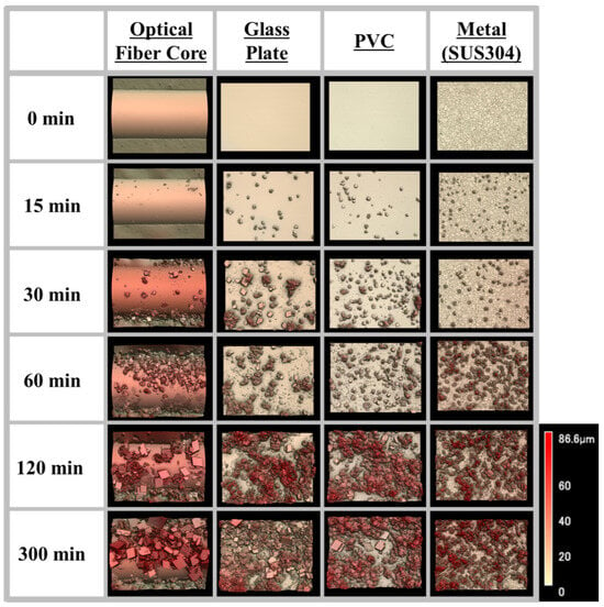
Figure 6.
Images of CaCO3 scale deposited on different materials (optical fiber core, glass plate, PVC, and metal plate) obtained using a shape analysis laser microscope.
Figure 7a shows the amount of scale coverage on the surface of each test piece as calculated from the 3D images using the image analysis software ImageJ 1.53, together with the measured transmittance. There is no difference in the amount of surface coverage on the different materials. In addition, the transmittance measured by the sensor is highly correlated with the scale coverage. These results suggest that the portable scale sensor could be used to monitor the deposition of scale in real time.
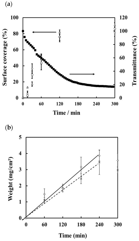
Figure 7.
(a) Transmittance measured by the portable sensor during the precipitation of CaCO3 scale (■) and percentage scale coverage on the surface of SUS304 (△), PVC (○), and a glass plate (◇). (b) Mass of scale deposited on test pieces of SUS304 (◇) and PVC (×).
The mass of scale deposited on the metal and PVC test pieces is shown in Figure 7b. From these results, the rate of scale deposition on each material was calculated for the time interval 0–240 min. The calibration curves that were derived showed that the rate of deposition (in mg/cm2/min) for SUS304 was equal to 0.0167 × time (R2 = 0.990) and for PVC (mg/cm2/min) = 0.0144 × time (R2 = 0.996). Based on these calibration curves and the sensor response, the following equation for the decrease in transmittance based on the rate constant, K, and the mass of precipitated scale was obtained:
where Δ%T = decrease in transmittance; K = rate constant; W = mass of precipitated scale. From the results the mass of scale was calculated as being equal to 36.941 × %T for SUS304 and 44.857 × %T for PVC. We thus conclude that it is possible to determine the amount of deposited scale from the transmittance measured using this sensor and the calculated rate constant, K.
Δ%T (min) = KW (mg/min),
3.4. Monitoring the Formation of Scale under High-Temperature, High-Pressure Conditions
To simulate the conditions in a geothermal fluid, a high-temperature, high-pressure vessel was specially fabricated (Figure S5). The reaction vessel was made of 316 stainless steel and had a reaction area of 80 mm. The fiber optic sensor was fixed to the vessel using a PEEK tube, front and rear ferrules, and nuts. A quantity of the test solution (5 mM NaHCO3 and CaCl2) calculated from the specific volume corresponding to each temperature (32, 32, 27, and 25 mL for 25, 100, 200, and 250 °C, respectively) was placed in the reaction vessel and heated by winding a tape heater. The reaction vessel is covered with heat insulating material and the temperature of reaction vessel was monitor during experiment. The transmittance response of the sensor was then measured using a 560 nm light source and a detector attached to the portable scale sensor. The length of the sensed area was fixed at 5 cm. Figure 8 shows the measured transmittance during the precipitation of calcium carbonate scale at each temperature and temperature profile. The reaction vessel reached a temperature of 250 °C after about 3 h, and the transmittance tended to increase as the temperature increased. This is because the refractive index of the solution decreased as its temperature increased, making it easier to satisfy the total internal reflection condition. The response of the sensor to the precipitation of calcium carbonate scale shows that the transmittance increased as the temperature of the solution increased. This is because the saturation index of calcium carbonate increases with increasing temperature; thus, the rate and amount of scale precipitation increased. These results suggest that a suitable high-temperature, high-pressure vessel can be used to simulate the process of scale formation in a geothermal fluid and that this sensor can be used to monitor this process. Scale formation under a range of temperatures and pressures can be simulated.
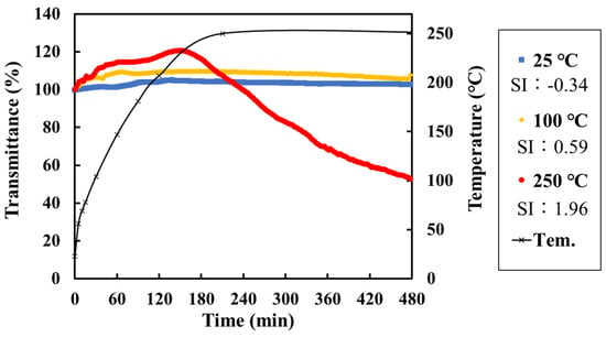
Figure 8.
Transmittance measured by the portable sensor during scale formation at different temperatures and the temperature profile of the reaction vessel: room temperature (25 °C) and SI of calcite = −0.34 (blue); 100 °C and SI of calcite = 0.59 (yellow); and 250 °C and SI of calcite = 1.96 (red).
3.5. Field Investigation
3.5.1. Rishiri Fureai Hot Spring
To further evaluate the applicability of the proposed sensor, we conducted a field test at the Rishiri Fureai hot spring on Rishiri Island, Hokkaido. Carbonated spring water flows naturally at this location; details of the chemical composition of the water are given in Table 1. The saturation index of the calcite was calculated to be 0.88, indicating that precipitation of calcium carbonate scale could be expected. Tests were conducted by directly immersing the scale sensor in a reaction vessel in which hot spring water flowed at a rate of 1.3 L/min. Figure 9a shows the transmittance of the water that was measured using the portable scale sensor. The transmittance decreased dramatically as scale was deposited on the sensor surface, and the transmittance gradually became saturated. Figure 9b,c show, respectively, the spectra and transmittance obtained using the nonportable scale sensor. As with the portable sensor, a decrease in transmittance was observed as the scale was deposited, and the decrease in transmittance was the same for both sensors. The results suggest that the portable scale sensor is suitable for the monitoring of scale formation in geothermal water and performs as well as the nonportable sensor. For both sensors, the decrease in the transmittance was found to depend on the wavelength. This was probably due to the precipitation of iron hydroxide and other compounds, as the conditions were different from those in the laboratory experiments where pure CaCO3 scale was deposited.

Table 1.
Chemical composition of water at the Rishiri Fureai hot spring and Onuma geothermal power plant.
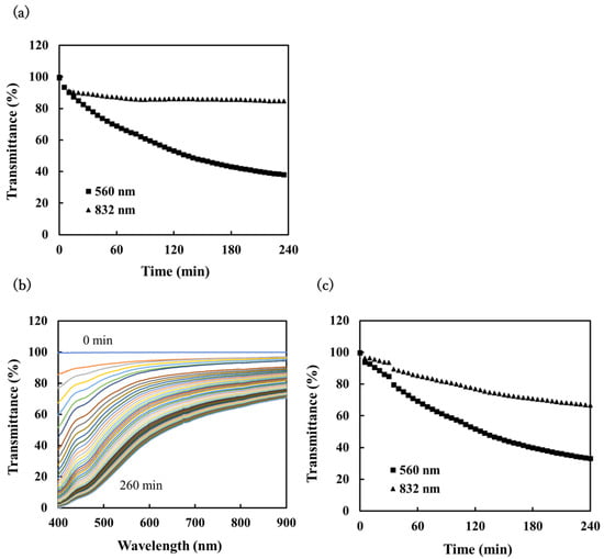
Figure 9.
The sensor response for scale precipitation in spring water at Rishiri Fureai hot spring: (a) change in transmittance with time at 560 nm (■) and 832 nm (▲) measured using the portable scale sensor, (b) change in the transmittance spectrum with time measured using the nonportable scale sensor, and (c) change in transmittance with time at 560 nm (■) and 832 nm (▲) as determined from the spectral measurements.
3.5.2. Onuma Geothermal Power Plant
A second field test was conducted at the Onuma geothermal power plant (O-12R), which has an output of 9500 kW and uses a single-flush system. The power plant is located in the city of Kazuno, Akita Prefecture. The chemical properties and chemical composition of the geothermal water flowing in O-12R are shown in Table 1. The concentration of silica in the water is high, and it is known that the scale precipitated here consists mainly of silica. Using both the portable and nonportable sensors, the transmittance of the water was measured as scale formed in the geothermal water; the results are shown in Figure 10. The measurements were carried out by immersing the sensing part of the fiber optic directly into the water at the plant. In both cases, the transmittance decreased as the immersion time in the measuring solution increased. The results suggest that the portable sensor could be used to monitor the deposition of scale in geothermal power plants in real time.
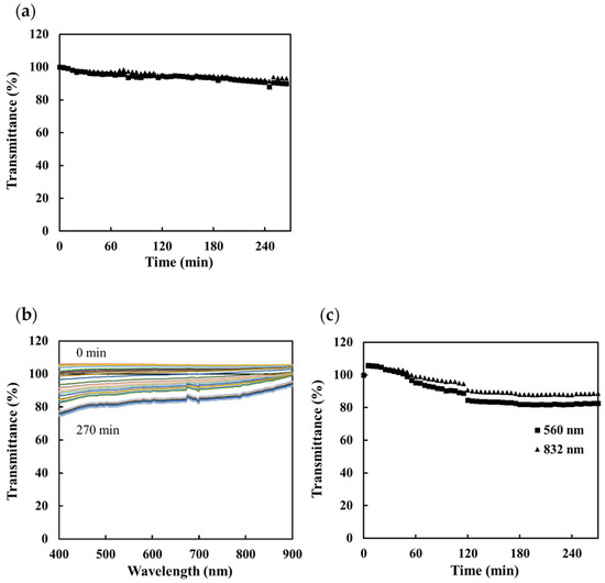
Figure 10.
The sensor response for scale precipitation in geothermal brine at the Onuma geothermal power plant: (a) change in transmittance with time at 560 nm (■) and 832 nm (▲) measured using the portable scale sensor, (b) change in the transmittance spectrum with time measured using the nonportable scale sensor, and (c) change in transmittance with time at 560 nm (■) and 832 nm (▲) as determined from the spectral measurements.
4. Conclusions
Geothermal power is one of the most promising carbon-neutral energy sources. The adoption and growth of geothermal power depends on the ability of geothermal power plants to operate for long periods of time, on the order of decades, without significant loss of efficiency. In this study, we developed a portable scale sensor that incorporates light sources, photodetectors, and a PC in one device. This was intended to be an improvement on sensors that are constructed using many different devices such as a spectroscope and a light source. The results obtained in the study suggest that this portable sensor can be used to monitor the formation of scale as well as a conventional sensor. Experiments were performed in which CaCO3 scale was precipitated onto various materials, and the surfaces of these materials were imaged. Based on these results, an equation that relates the amount of expected scale precipitation to the decrease in transmittance measured by the portable sensor was derived. The results of subsequent experiments suggest that the proposed sensor could be used to monitor the precipitation of scale from geothermal water in real time. This would make it useful for in situ real-time monitoring of scale formation in geothermal power plants and for evaluating the effectiveness of scale inhibitors.
Supplementary Materials
The following supporting information can be downloaded at: https://www.mdpi.com/article/10.3390/chemosensors12090171/s1, Figure S1. Block diagram of the portable scale sensor; Figure S2. (a) The portable scale sensor. (b) The sensor response for calcium carbonate scale precipitation measured using the conventional (watch glass) sensor arrangement and the U-shaped arrangement shown in Figure 2; Figure S3. Images of the surface of the optical fiber core and the optical fiber jacket after immersion in calcium sulfate solution; Figure S4. The change in the depth of the scale as measured along on a line near the center of the different test pieces after being immersed in CaCO3 solution for 300 min. Figure S5. Diagram of the fabricated high-temperature, high-pressure vessel; Figure S6. Experimental setup for the monitoring the formation of scale under high-temperature, high-pressure conditions.
Author Contributions
Conceptualization, H.K.; methodology, T.O. and H.K.; investigation, T.M., T.O., K.S. and H.K.; re-sources, K.S. and H.K.; writing—original draft preparation, T.M. and H.K.; writing—review and editing, T.O., K.S., A.H., A.U. and H.K.; visualization, T.M., T.O., K.S., A.H. and H.K.; supervision, A.U. and H.K.; project administration, A.U. and H.K.; funding acquisition, A.U. and H.K. All authors have read and agreed to the published version of the manuscript.
Funding
New Energy and Industrial Technology Development Organization (NEDO) projects: Research and development of geothermal power generation technology/Development of technology for advanced use of geothermal energy/Development of chemical processing systems in order to properly utilize acid brine and JOGMEC project in the R&D project “Carbon Recycling CO2 Geothermal Power Generation Technology”.
Institutional Review Board Statement
Not applicable.
Informed Consent Statement
Not applicable.
Data Availability Statement
The data are contained within the article and its Supporting Information.
Acknowledgments
This research was conducted as part of the New Energy and Industrial Technology Development Organization (NEDO) projects: Research and development of geothermal power generation technology/Development of technology for advanced use of geothermal energy/Development of chemical processing systems to properly utilize acid brine. A part of this study was re-commissioned by Taisei Corporation as a part of the JOGMEC project investigation in the R&D project “Carbon Recycling CO2 Geothermal Power Generation Technology”. We would like to thank the members of JOGMEC and Taisei Corporation for their cooperation. The authors wish to thank Mitsubishi Materials Corp., Hachimantai Geothermal Corp., and Rishiri Fureai Hot Spring for their kind cooperation during our fieldwork and permitting us to use the chemical data of geothermal brine.
Conflicts of Interest
The authors declare no conflicts of interest.
References
- “Key World Energy Statistics 2019”. Available online: https://www.oecd.org/en/publications/key-world-energy-statistics-2019_71b3ce84-en.html (accessed on 22 August 2024).
- Strezov, V.; Cho, H.H. Environmental impact assessment from direct emissions of australian thermal power generation technologies. J. Clean. Prod. 2020, 270, 122515. [Google Scholar] [CrossRef]
- Agrawal, K.K.; Jain, S.; Jain, A.K.; Dahiya, S. Assessment of greenhouse gas emissions from coal and natural gas thermal power plants using the life cycle approach. Int. J. Environ. Sci. Technol. 2014, 11, 1157–1164. [Google Scholar] [CrossRef]
- Akella, A.K.; Saini, R.P.; Sharma, M.P. Social, economical and environmental impacts of renewable energy systems. Renew. Energy 2009, 34, 390–396. [Google Scholar] [CrossRef]
- Fridleifsson, I.B. Geothermal energy for the benefit of the people. Renew. Sustain. Energy Rev. 2001, 5, 299–312. [Google Scholar] [CrossRef]
- Pátzay, G.; Stáhl, G.; Kármán, F.H.; Kálmán, E. Modeling of scale formation and corrosion from geothermal water. Electrochim. Acta 1998, 43, 137–147. [Google Scholar] [CrossRef]
- Alabi, A.; Chiesa, M.; Garlisi, C.; Palmisano, G. Advances in anti-scale magnetic water treatment. Environ. Sci. Water Res. Technol. 2015, 1, 408–425. [Google Scholar] [CrossRef]
- MacAdam, J.; Parsons, S.A. Calcium carbonate scale formation and control. Rev. Environ. Sci. Biotechnol. 2004, 3, 159–169. [Google Scholar] [CrossRef]
- Dalas, E. The effect of ultrasonic field on calcium carbonate scale formation. J. Colloid. Interface Sci. 1993, 155, 512–514. [Google Scholar] [CrossRef]
- Ueda, A.; Kato, H.; Miyauchi, T.; Kato, K. Investigation of pH Control Method to Avoid Silica Scaling in the Sumikawa Geothermal Field. J. Geotherm. 2003, 25, 163–177. [Google Scholar]
- Ikeda, R.; Ueda, A. Experimental field investigations of inhibitors for controlling silica scale in geothermal brine at the Sumikawa geothermal plant, Akita Prefecture, Japan. Geothermics 2017, 70, 305–313. [Google Scholar] [CrossRef]
- Hanajima, E.; Ueda, A. Recovery of oversaturated silica from Takigami and Sumikawa geothermal brines with cationic polymer flocculants to prevent silica scale deposition. Geothermics 2017, 70, 271–280. [Google Scholar] [CrossRef]
- Li, J.; Zhou, Y.; Yao, Q.; Wang, T.; Zhang, A.; Chen, Y.; Wu, W.; Sun, W. Preparation and Evaluation of a Polyether-Based Polycarboxylate as a Kind of Inhibitor for Water Systems. Ind. Eng. Chem. Res. 2017, 56, 2624–2633. [Google Scholar] [CrossRef]
- Li, X.; Gao, B.; Yue, Q.; Ma, D.; Rong, H.; Zhao, P.; Teng, P. Effect of six kinds of scale inhibitors on calcium carbonate precipitation in high salinity wastewater at high temperatures. J. Environ. Sci. 2015, 29, 124–130. [Google Scholar] [CrossRef] [PubMed]
- Ueda, A.; Kato, K.; Mogi, K.; Mroczek, E.; Thain, I.A. Silica removal from Mokai, New Zealand, geothermal brine by treatment with lime and a cationic precipitant. Geothermics 2003, 32, 47–61. [Google Scholar] [CrossRef]
- Hirowatari, K. Scale prevention method by brine acidification with biochemical reactors. Geothermics 1996, 25, 259–270. [Google Scholar] [CrossRef]
- Gallup, D.L. Investigations of organic inhibitors for silica scale control in geothermal brines. Geothermics 2002, 31, 415–430. [Google Scholar] [CrossRef]
- Fidanboylu, K.; Efendioglu, H.S. Fiber Optic Sensors and Their Applications; MDPI: Basel, Switzerland, 2020. [Google Scholar] [CrossRef]
- Wang, X.-D.; Wolfbeis, O.S. Fiber-Optic Chemical Sensors and Biosensors (2015–2019). Anal. Chem. 2020, 92, 397–430. [Google Scholar] [CrossRef]
- Wang, Q.; Zhang, D.; Qian, Y.; Yin, X.; Wang, L.; Zhang, S.; Wang, Y. Research on Fiber Optic Surface Plasmon Resonance Biosensors: A Review. Photonic. Sens. 2024, 14, 240201. [Google Scholar] [CrossRef]
- Fu, R.; Chen, X.; Yan, X.; Li, H.; Hu, T.; Wei, L.; Qu, Y.; Cheng, T. Optical fiber sensors for heavy metal ion sensing. J. Mater. Sci. Technol. 2024, 189, 110–131. [Google Scholar] [CrossRef]
- Li, X.; Li, Y.; Wei, H.; Wang, C.; Liu, B. A review of wearable optical fiber sensors for rehabilitation monitoring. Sensors 2024, 24, 3602. [Google Scholar] [CrossRef]
- Lu, M.; Wang, C.; Fan, R.; Lin, M.; Guang, J.; Peng, W. Review of fiber-optic localized surface plasmon resonance sensors: Geometries, fabrication technologies, and bio-applications. Photonic Sens. 2024, 14, 240202. [Google Scholar] [CrossRef]
- Wang, W.; Xia, L.; Xiao, X.; Li, G. Recent progress on microfluidics integrated with fiber-optic sensors for on-site detection. Sensors 2024, 24, 2067. [Google Scholar] [CrossRef]
- Kourti, D.; Angelopoulou, M.; Petrou, P.; Kakabakos, S. Optical immunosensors for bacteria detection in food matrices. Chemosensors 2023, 11, 430. [Google Scholar] [CrossRef]
- Leitão, C.; Pereira, S.O.; Marques, C.; Cennamo, N.; Zeni, L.; Shaimerdenova, M.; Ayupova, T.; Tosi, D. Cost-effective fiber optic solutions for biosensing. Biosensors 2022, 12, 575. [Google Scholar] [CrossRef]
- Janik, M.; Koba, M.; Śmietana, M. Optical fiber chemo and biosensors operating in the electrochemical domain–A review. TrAC Trends Anal. Chem. 2024, 178, 117829. [Google Scholar] [CrossRef]
- Fakhri, M.A.; Salim, E.T.; Tariq, S.M.; Ibrahim, R.K.; Alsultany, F.H.; Alwahib, A.A.; Alhasan, S.F.H.; Gopinath, S.C.; Salim, Z.T.; Hashim, U.; et al. A gold nanoparticles coated unclad single mode fiber-optic sensor based on localized surface plasmon resonance. Sci. Rep. 2023, 13, 5680. [Google Scholar] [CrossRef]
- Antohe, I.; Iordache, I.; Antohe, V.A.; Socol, G. A polyaniline/platinum coated fiber optic surface plasmon resonance sensor for picomolar detection of 4-nitrophenol. Sci. Rep. 2021, 11, 10086. [Google Scholar] [CrossRef] [PubMed]
- Usha, S.P.; Shrivastav, A.M.; Gupta, B.D. Silver nanoparticle noduled ZnO nanowedge fetched novel FO-LMR based H2O2 biosensor: A twin regime sensor for in-vivo applications and H2O2 generation analysis from polyphenolic daily devouring beverages. Sens. Actuators B Chem. 2017, 241, 129–145. [Google Scholar] [CrossRef]
- Fan, S.-M.; Chiang, C.-Y.; Tseng, Y.-T.; Wu, T.-Y.; Chen, Y.-L.; Huang, C.-J.; Chau, L.-K. Detection of Hg(II) at part-per-quadrillion levels by fiber optic plasmonic absorption using DNA hairpin and DNA-gold nanoparticle conjugates. ACS Appl. Nano Mater. 2021, 4, 10128–10135. [Google Scholar] [CrossRef]
- Sharma, S.; Gupta, B.D. Surface plasmon resonance based fiber optic potassium ion disposable sensing probe for soil testing. Opt. Fiber Technol. 2021, 64, 102573. [Google Scholar] [CrossRef]
- Orii, T.; Okazaki, T.; Hata, N.; Sugawara, K.; Rahman, F.A.; Kuramitz, H. Development of an attenuated total reflection -based fiber-optic sensor for real-time sensing of biofilm formation. Anal. Sci. 2017, 33, 883–887. [Google Scholar] [CrossRef]
- Imai, K.; Okazaki, T.; Hata, N.; Taguchi, S.; Sugawara, K.; Kuramitz, H. Simultaneous multiselective spectroelectrochemical fiber-optic sensor: Demonstration of the concept using methylene blue and ferrocyanide. Anal. Chem. 2015, 87, 2375–2382. [Google Scholar] [CrossRef] [PubMed]
- Okazaki, T.; Shiokawa, E.; Orii, T.; Yamamoto, T.; Hata, N.; Taguchi, A.; Sugawara, K.; Kuramitz, H. Simultaneous Multiselective Spectroelectrochemical Fiber-Optic Sensor: Sensing with an Optically Transparent Electrode. Anal. Chem. 2018, 90, 2440–2445. [Google Scholar] [CrossRef] [PubMed]
- Okazaki, T.; Kuramitz, H.; Watanabe, T.; Ueda, A. Scale sensor: Rapid monitoring of scale deposition and inhibition using fiber optics in a geothermal system and comparison with other monitoring devices. Geothermics 2021, 93, 102069. [Google Scholar] [CrossRef]
- Okazaki, T.; Yamamoto, T.; Taguchi, A.; Ueda, A.; Kuramitz, H. Fiber Optic Sensor with an Optically Transparent Electrode for Monitoring CaCO3 Scale Formation in Geothermal Water. IEEE Sens. Lett. 2017, 1, 1–4. [Google Scholar] [CrossRef]
- Okazaki, T.; Orii, T.; Ueda, A.; Kuramitz, H. A Reusable Fiber Optic Sensor for the Real-Time Sensing of CaCO3 Scale Formation in Geothermal Water. IEEE Sens. J. 2017, 17, 1207–1208. [Google Scholar] [CrossRef]
- Okazaki, T.; Orii, T.; Ueda, A.; Ozawa, A.; Kuramitz, H. Fiber Optic Sensor for Real-Time Sensing of Silica Scale Formation in Geothermal Water. Sci. Rep. 2017, 7, 3387. [Google Scholar] [CrossRef]
- Okazaki, T.; Umeki, S.; Orii, T.; Ikeya, R.; Sakaguchi, A.; Yamamoto, T.; Watanabe, T.; Ueda, A.; Kuramitz, H. Investigation of the effects of electromagnetic field treatment of hot spring water for scale inhibition using a fibre optic sensor. Sci. Rep. 2019, 9, 3–10. [Google Scholar] [CrossRef] [PubMed]
- Okazaki, T.; Imai, K.; Tan, S.Y.; Yong, Y.T.; Rahman, F.A.; Hata, N.; Taguchi, S.; Ueda, A.; Kuramitz, H. Fundamental study on the development of fiber optic sensor for real-time sensing of CaCO3 scale formation in geothermal water. Anal. Sci. 2015, 31, 177–183. [Google Scholar] [CrossRef]
- Zotzmann, J.; Hastreiter, N.; Mayanna, S.; Reinsch, T.; Regenspurg, S. A fibre-optical method for monitoring barite precipitation at high pressure/high temperature conditions. Appl. Geochem. 2021, 127, 104906. [Google Scholar] [CrossRef]
- Hashimoto, R.; Morita, M.; Umezawa, O.; Motoda, S. Effect of Ions Eluted from Metal Surface on Transformation and Growth of Calcium Carbonate Polymorphisms. J. Jpn. Inst. Met. Mater. 2017, 81, 89–96. [Google Scholar] [CrossRef]
Disclaimer/Publisher’s Note: The statements, opinions and data contained in all publications are solely those of the individual author(s) and contributor(s) and not of MDPI and/or the editor(s). MDPI and/or the editor(s) disclaim responsibility for any injury to people or property resulting from any ideas, methods, instructions or products referred to in the content. |
© 2024 by the authors. Licensee MDPI, Basel, Switzerland. This article is an open access article distributed under the terms and conditions of the Creative Commons Attribution (CC BY) license (https://creativecommons.org/licenses/by/4.0/).