Abstract
The three-layer electrode consisting of the inner, middle, and outer layers of polythiophene (PTh), polyaniline (PANI), and poly(neutral red) (PNR), respectively, was developed, characterized, and tested as a potentiometric sensor for citrates. The spectroscopic and morphological findings based on Raman spectroscopy and scanning electron microscopy, respectively, demonstrated the consecutive formation of individual polymeric layers derived from PTh, PANI, and PNR in the multilayer system. The sharper and narrower peak profiles of PNR in the case of the three-layer system revealed a more organized structure than for the PNR layer alone. The PNR layer in such a novel arrangement shows the highest selectivity towards citrates among the tested carboxylates. Simultaneously, the unwanted influence of the underlying Pt surface is eliminated. The potentiometric characteristics of the proposed potentiometric sensor were examined at the detection of citrates in the real-world samples, compared with results for PNR simple electrode, and corresponded with the reference capillary electrophoresis and literature-based spectrophotometric method.
1. Introduction
The potentiometric response to the target analyte is affected by the electrode substrate material (Pt, Au). Hence, it is very important to eliminate this metal influence. Platinum itself readily reacts in the presence of redox systems such as ascorbic acid, halides, and other ions [1,2] as well as influences the stability of potentiometric signals [3]. One effective solution is to coat the surface with a thicker layer [4] or with multilayers [5]. Conducting polymers have a variety of chemical and physical properties predisposing them to be widely used as sensitive layers in chemical sensors [6,7,8,9]. The application of several individual polymers layered on each other changes both electrochemical and optical properties. In the literature, the electrochemical properties of bilayer polymeric films composed of polypyrrole (PPy) and polythiophene (PTh) derivatives [10], PPy and polyaniline (PANI) [11,12,13], and some other derivatives [14,15] were described. The additional polymer layers such as PANI or PPy can function as lipophilic additives. The additive should simplify ion exchange between a specific layer and the target analyte [16].
Polymer films based on poly(neutral red) (PNR) offer a combination of several different binding modes including ion exchange, ion-dipole, and π-π interactions, or hydrogen bonds. These binding modes make PNR a suitable candidate for the construction of electrochemical sensors for the detection of carboxylates [17]. Poly(neutral red) modified electrodes, in addition to the potentiometric determination of citrates [7,17], are used as well for the voltammetric determination of mandelic and vanillic acid derivatives [18]. For the development of any sensor, it is important to improve the properties that increase its analytical significance. The application of several individual polymers layered on top of each other can positively influence the electrochemical and analytical properties of these electrodes.
Murray et al. conducted the first research aimed at the electrochemical properties of bilayer films [19]. They dealt with electron transfer through a polymer-polymer interface demonstrating the importance of the ionic conductivity of the system for the development of potentiometric sensors based on conducting polymers. Ren and Pickup found that the ionic conductivity of a bilayer polymer system is conditioned by the mobility of ions in the individual layers [20]. It has been shown that the inner layer cannot transfer charge unless the outer layer is permeable to ions. Later Wojda et al. described the potentiometric properties of bilayers [21]. They proposed a theoretical model of the potentiometric response of a bilayer as a function of electrolyte concentration, with electrolyte concentration being dependent on the equilibrium processes at the interface and the transport of ions through the layers [21]. Among the advantages of the bilayer electrode system is the stability of the potential measured in both aqueous and organic solvents containing different electrolyte concentrations documented using a bilayer system composed of PPy and poly(3-methyl-thiophene) as a reference electrode [22].
The polymer bilayer deposited on a platinum wire can be regarded as a coaxial coating as reported in the literature [23,24]. Coaxial nanotubes are produced on an inorganic nanotubular template coated with an outer layer of conductive polymers, mostly represented with PANI. Several authors have additionally remarked on the effect of the used substrate on the morphology of the bilayer system [13,25] and the potentiometric signal [4]. Alumaa et al. observed the influence of the metal support on the potentiometric response of their bilayer system [4]. Therefore, it is necessary to combine rationally selected polymer layers to suppress completely the influence of the underlying metallic material on the measured signal.
In our concept of a multilayer system, the PTh was chosen as the first/inner layer to shield/protect the support metallic material. In addition, PTh can help during the polymerization of the middle layer, which was composed of PANI. In a previous study, PPy was used as a non-specific layer. However, this polymer did not improve the binding properties of the PNR film to citrate [5]. In this study, we select PANI as the middle layer, expecting a significant improvement in sensitivity and selectivity to citrate ions. This polymer forms an unmodified polymer layer responsive to non-selectively reacting ions. The outer specific layer consisted of poly(neutral red) (PNR) reacting selectively to citrate, as we demonstrated previously [7,17].
In addition to potentiometry, other instrumental methods such as FT Raman spectroscopy (FT-Raman) and scanning electron microscopy (SEM) are used to monitor the presence of polymer layers. PNR forms visible colored films readily soluble in DMSO [7], which can serve as primary evidence of its presence on other polymer layers. At the same time, the UV-vis spectrometric method can be used to elucidate further the structure and properties of the polymer formed of NR. In this present work, we tested the properties of PNR by bi- and three-layer electrode systems. Furthermore, we examined whether a well-designed multilayer polymer system could improve the properties of PNR electrodes such as selectivity, stability, and the accuracy of citrate determination in a real-world sample.
2. Materials and Methods
2.1. Chemicals
The monomers of neutral red (NR) (3-amino-7-dimethylamino-2-methyl phenazine, Lachema, Brno, Czech Republic), aniline.H2SO4 (Sigma Aldrich, St. Louis, MO, USA), and thiophene (98%; Sigma Aldrich) and solvents of acetonitrile (min 99.5%; Sigma Aldrich) with tetrabutylammonium perchlorate (TBAP, Fluka, Buchs, Switzerland) and H2SO4 with/without polyvinylpyrrolidone (PVP; Fluka) were used for the polymerization. The other standard chemicals (all inorganic salts and acids) were purchased from Penta (Prague, Czech Republic) or Lachema (Brno, Czech Republic). All working solutions were prepared using redistilled water. Real-world samples of drinks (Gatorade, Mountain Dew) were obtained from a local store (Prague, Czech Republic).
2.2. Preparation of Electrode Systems
Electropolymerization of the polymer layers was performed with a PA 2 polarographic analyzer (Laboratory devices, Prague, Czech Republic), supplemented with an adapter for cyclic voltammetry (Institute of Analytical Chemistry, UCT Prague, Czech Republic). Polymerizations were always terminated at a positive limiting potential. The electrode cell was composed of a polymer-modified Pt wire working electrode (size 8 × 0.4 mm [7]), a saturated Ag/AgCl reference electrode, and an auxiliary Pt plate (with dimensions 8–12 mm and thickness 0.3 mm). The electrolyte was bubbled with nitrogen for about 10 min before polymerization. The conditions for the preparation of the polymer-modified electrodes using cyclic voltammetry are summarized in Table 1.

Table 1.
Conditions for the electropolymerized individual and multilayers. All polymers were prepared at the scan rate of 100 mV s−1.
Firstly, individual polymers (PTh, PANI, PNR) were prepared, then bilayers marked as (PTh-PANI and PTh-PNR) and further two types of three-layer systems differing in sequences of layers (PTh-PANI-PNR and PTh-PNR-PANI). The resulting electrodes were immersed in redistilled water immediately after the completion of the electropolymerization process.
2.3. Spectroscopic Characterization
Raman spectra of PNR were reasonably obtained only on the polymer-modified gold-plated surface of Pt plates with dimensions of 0.5 × 1.0 cm and a thickness of 0.2 mm [26,27]. The spectra of powdered NR were collected in a glass vial. The spectra of other polymers (PTh, PANI, bilayers, and three-layer systems) were acquired on Pt plates without prior gold plating.
An FRA 106/S FT Raman module (Bruker, Ettlingen, Germany) connected to Equinox 55/S Fourier-transform near-infrared spectrometer was employed to collect Raman spectra excited at 1064 nm using the Nd-YAG laser (Coherent, Santa Clara, CA, USA). The applied laser power was less than 50 mW. 512 or 1024 interferogram accumulations resulted in an individual 2-cm−1 resolved spectrum. OPUS software (Bruker, Germany) controlled the spectrometric system and primarily processed spectral data. The OMNIC software package (Thermo Scientific, Waltham, MA, USA) was used for further data processing and assessment.
The morphology of all prepared polymers was studied using a scanning electron microscope JSM 6400 (JEOL, Tokyo, Japan). It worked at a voltage of 25 kV. All samples were sputtered with platinum to a thickness of 10 nm under vacuum (SCD 050, BalTech, Pfäffikon, Switzerland) before analysis. Polymers (single, bi-, and three-layers) were prepared under the identical conditions listed in Table 1 and on the same Pt plates as in the case of Raman spectra accumulations.
UV–vis spectra of the NR monomer and polymer (PNR) were recorded on a Cary Varian 400 Scan instrument (Varian, Belrose, Australia) in the wavelength range of 350–700 nm with a resolution of 1 nm and a scanning speed of 600 nm/min in a 1-cm quartz cuvette. First, the monomer and polymer were dissolved only in DMSO, and the spectra were collected. To monitor the dependence of absorbance on pH, stock solutions of monomer and polymer dissolved in 0.05 M MES with 0.1 M NaCl of pH 4–8 were prepared. The monomer concentration was 1 × 10⁻⁴ M to achieve absorbance around 1. Monomer and polymer were first dissolved in 150 μL DMSO and then added into a 25 mL volumetric flask with 0.05 M MES solution containing 0.1 M NaCl. The pH of the solutions was properly adjusted using NaOH and H2SO4.
2.4. Potentiometric Properties of Multilayer Polymer Electrodes
2.4.1. Calibration, Selectivity, and Stability
For the potentiometric measurements, we used an ion-selective electrode (ISE) tester [28] that consisted of an analog unit box; autosampler with a sampling needle; hot-air thermostat; measuring cell; peristaltic pump, and computer with a PC 516 data acquisition card. The pH values were measured with a PHI 04 MG pH-Meter (Labio, Prague, Czech Republic) and monitored using a SEUJ 212 glass electrode (Monokrystaly, Turnov, Czech Republic). Our multilayer electrodes were composed of followed individual layers (PTh, PANI, PNR, PTh-PANI, PTh-PNR, PTh-PANI-PNR, PTh-PNR-PANI).
Subsequently, the individual dependences of the potential of the multilayer electrodes on the carboxylate’s concentration in a mixture of TRIS with KNO3 were acquired, as in the case of the PNR electrodes themselves [7,17]. The polymer electrode systems were conditioned for several days in distilled water for film maturation after preparation. Before the potentiometric measurement, they were left for 30 min in a citrate solution of a 10−3 M concentration. The calibration of the electrodes was performed in 0.02 M TRIS buffer with 0.1 M KNO3 (pH 8.5). To carefully regenerate electrode surfaces (to stabilize the potentiometric response), the tested electrodes were washed with distilled water and immersed in a solution containing 1 mM sodium citrate in TRIS buffer with KNO3 (pH 8.5).
The potentiometric selectivity coefficient values (KpotCitr,J, where J is different carboxylates (adipate, glutarate, malate, succinate, malonate, mandelate, terephthalate) and ascorbate) were determined by the fixed interference method (FIM) [7,29]. A detailed explanation and the equation for FIM are reported in (Supplementary Materials Figure S1).
The response time of the modified electrodes was determined for 10−3–10−1 M sodium citrate. Electrodes were conditioned in 10−3 M sodium citrate. The stability of modified electrodes (PNR and PTh-PANI-PNR) was monitored by repeated measurements of sodium citrate in the concentration range 10−3–10−1 M for four weeks.
2.4.2. Real-World Sample Analysis
The prepared electrodes were first left in distilled water for several days and calibrated in solutions of sodium citrate dissolved in TRIS (0.02 M) and NaNO3 (0.1 M) at pH 8.5 [17]. The citrate content was determined in real drinks such as Gatorade and Mountain Dew. To eliminate the interference of CO2 present in the real-world samples, the analyzed samples were stirred for 30 min. During these experiments, it was important to keep pH 8.5. This pH value was kept using 0.02 M TRIS buffer with adding 0.1 M NaNO3. In the case of a deviation of pH value from 8.5, solid-state NaOH was used. The degassed sample was tenfold diluted using 0.02 M TRIS buffer. 10 mL aliquot of diluted sample was analyzed by the method of standard addition [17]. The used equation of the standard addition method [30] is given in Supplementary Materials. The necessary potentiometric signal used for the calculation of citrate concentration in the sample was obtained after additions of 100 μL of 0.1 M sodium citrate. The electrodes were regenerated cautiously in distilled water for 30 min [17].
3. Results and Discussion
3.1. Polymerized Multilayer Electrode Preparation by Cyclic Voltammetry
The method of cyclic voltammetry was used for the formation of adherent polymer layers, where the corresponding polymer was formed by anodic oxidation of the monomer. The polymerization conditions of all derivatives are summarized in Table 1.
Cyclic voltammograms of individual layers (Figure 1a,b) served to confirm the course of polymerization of individual polymers of multilayer electrodes (Figure 1c,d). PTh was prepared from acetonitrile with the addition of TBAP according to a standard procedure described in the literature [31]. Electrochemically generated PTh forms stable films in both the doped and undoped state and, as unsubstituted, is practically insoluble in common solvents [31]. A dark brown to black film visible to the naked eye was created within a short time, approx. 2–3 min (Figure 1b). If the PTh coating was polymerized for a longer time (more than 10 min), then thick layers were formed, and they often peeled off. The optimal PTh preparation time was 4 min, with a shorter polymerization time (less than 4 min) the Pt surface was not completely covered by the film. Adhering PTh served as a base layer homogeneously covering the Pt surface and at the same time as a catalyst facilitating and above all accelerating the polymerization of other layers. Polymerization of PNR to both Pt (Figure 1a) and PTh proceeded well from both aqueous and non-aqueous environments. Acetonitrile was chosen as the medium for the preparation of multilayer systems [5,17].
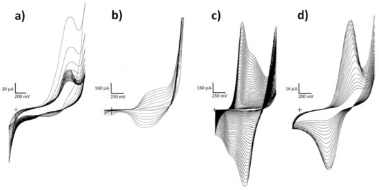
Figure 1.
Cyclic voltammograms of PNR on Pt (a) and of the step-by-step preparation of a three-layer electrode system PTh-PANI-PNR composed of PTh on Pt (b); PANI on PTh (c) and PNR on PTh-PANI bilayer (d). (The “+” corresponds to the crossing of the x and y-axis in zero.)
According to the literature, PANI can be prepared from both aqueous [32] and non-aqueous media [33]. For multilayer systems, an aqueous environment of dilute sulphuric acid with 2% PVP was chosen. The course of electropolymerization corresponded to the records given in the literature [32]. PVP acts as a steric stabilizer or “cleaner” because it removes side chains and thus ensures the formation of a regular structure of PANI [34]. It was found that the polymerization of PANI from an organic medium on the PTh layer did not occur, as there were no visible changes in the cyclic voltammogram. On the contrary, the polymerization of PANI on PTh was shown to run very well only from an aqueous medium, as shown in Figure 1c. The PNR polymerization proceeded well from both environments (aqueous and non-aqueous). However, an organic environment was used for the preparation of multilayer systems, since during the preparation of PANI it was observed that cyclization in dilute sulphuric acid causes its gradual dissolution.
Cyclic voltammograms of PNR on Pt and the bilayer PTh-PANI system are compared in Figure 1. From the course of the PNR deposition on the PTh-PANI system (Figure 1d), it can be assumed that PNR polymerization took place, as the observed peaks remained. However, they cannot be clearly distinguished from the PANI polymer film peaks. The presence of PNR on the surface of the bilayer system was then easily demonstrated by the subsequent dissolution of the colored PNR film in DMSO or spectroscopically, as will be described later.
Based on the size of the current, the conductivity of the PNR film prepared from an organic medium is quite low compared to the PTh and PANI layer, which furthermore corresponds to the size of the current when depositing the PNR top layer on the Pt-Pth-PANI system.
3.2. Characterization of Multilayer Polymer Systems
3.2.1. Raman Spectroscopy
Individual layers prepared by the CV method on gold-plated and non-gold-plated Pt plates were characterized by Raman spectroscopy (Figure 2). First, the spectra of individual polymers PTh (Figure 2a), PANI (Figure 2c), and PNR (Figure 2e) were collected, then PANI was deposited on PTh, the spectrum was acquired (Figure 2b) and finally PNR was deposited on this bilayer as the third (outer) layer labeled PTh-PANI-PNR (Figure 2d).
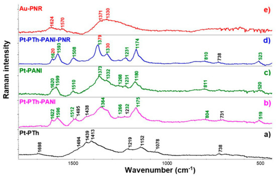
Figure 2.
Raman spectra of individual polymer layers of PTh (a)—black, PANI (c)—green, and PNR (e)—red, a bilayer of the PTh-PANI (b) and three-layer of PTh-PANI-PNR system (d), when the middle layer of PANI was overlaid with a PNR polymer. Black, green, and red numbers indicate PTh, PANI, and PNR bands, respectively. The PNR itself was deposited on a gold-plated Pt plate, while the other polymers were on non-gold-plated platinum plates. (Two-color numbers corresponds to the same bands of different polymers).
In the spectrum of PTh (Figure 2a), a broad band in the interval 1550 to 1300 cm−1 consists of several overlapping bands, from which two maxima at ca. 1439 and 1413 cm−1 and a shoulder at 1494 cm−1 are visible. These bands correspond to in-plane symmetric (1439 and 1413 cm−1) and antisymmetric vibrations (1494 cm−1) of the thiophene skeleton with a dominant share of C=C bond vibrations. The band at 1219 cm−1 was assigned to C-C stretching vibrations of the thiophene ring and 1078 cm−1 corresponds to C-H deformation vibrations on this ring. The deformation vibrations of the PTh ring (Cα-S-Cα’) are evident by a typical band at 738 cm−1 [35].
In the spectrum of PANI (Figure 2c), C=C ring stretching and C=N stretching vibrations [36] are visible at 1599 cm−1 and 1510 cm−1, respectively. The band at 1620 cm−1 can be assigned to the deformation mode of the –NH- group or the ring in-plane vibration of –(C-C)Ar. Coupled C-N and C-C vibrations in PANI are observed at 1373 and 1231 cm−1 and the band at 1180 cm−1 tentatively corresponds to strain C-H vibrations. At 811 cm−1, a characteristic band of out-of-plane deformation vibrations of the ring occurs [37].
After the formation of a bilayer film from PTh and PANI, the characteristic bands of the outer PANI polymer (marked with green numbers: 1622, 1596, 1512, 1364, 1232, 1175, and 804 cm−1) are observed in the spectrum (Figure 2b) as for PANI itself, but it is also possible to identify clearly PTh bands at 1495, 1438 and 731 cm−1 (black numbers).
In the PNR spectrum (Figure 2e), broad bands of in-plane vibrations of the phenazine ring were observed at 1570 cm−1 (vibrations with a dominant share of C=C vibrations), 1371 and 1330 cm−1 (ring vibrations with a coupling of C-C and C-N vibrations). The first mentioned band at 1570 cm−1 is significantly shifted compared to the similar band in the PANI spectrum (1599 cm−1), which may be related to the fact that (i) the structure of the polymer skeleton formed by neutral red polymerization is significantly different from the structure of PANI, (ii) in the case of PANI, it is known from the literature [37] that the position of the band is influenced by the redox state of the polymer and (iii) the underlying material may also have a non-negligible influence [38]. The band at 1624 cm−1 is attributed to the deformation mode of the -NH- group and the in-plane –(C-C)Ar ring vibrations, similar to PANI.
After applying the third layer, namely PNR, bands of all three polymers are visible in the collected spectrum (Figure 2d), the black numbers indicate the bands of the PTh layer (738 cm−1), the non-overlapped modes of PANI are marked again in green (1593, 1508, 1231, 1174, 810 and 520 cm−1), the vibrations of the PNR skeleton somewhat overlapping with bands of PANI (1620, 1379 and 1330 cm−1) are marked in a combination of red and green.
The spectrum of the three-layer PTh-PANI-PNR system differs from the spectrum of the two-layer Pt-Pth-PANI (Figure 2b), i.e., without PNR. Especially, the two bands at 1379 and 1330 cm−1 are well-pronounced (the shoulder at 1570 cm−1 is visible). The three mentioned positions correspond reasonably to the maxima observed for the Au-PNR system (Figure 2e). Hence, even overlapped with PANI bands, we can assign them to the presence of PNR. The bands assigned to the PNR in the three-layer system are sharper and narrower than for simple Au-PNR itself demonstrating better order of the outer PNR layer on the middle PANI layer.
From the Raman spectra, it was found that also the structures of (a) PANI on the underlying PTh layer and (b) PNR polymer on the PTh-PAN bilayer are better ordered, as evidenced by narrower peaks in the spectra, than single corresponding layer systems—(Pt-PANI and Pt/Au-PNR). Raman spectroscopy of the rational set of single, double, and three-layer electrode systems showed the formation of multilayer polymer films and their ordering. The formation of the different three-layer systems was also examined when the order of the second and third layers of the polymers was interchanged, that is for the Pt-PTh-PNR-PANI (not shown here).
3.2.2. Electron Microscopy
SEM researched the coverage, homogeneity, and morphology of the prepared films. It is undoubtedly evident from Figure 3 that each polymer has a different morphology depending on the substrate used [13,25]. The PNR film on Pt itself, prepared from an organic medium, forms a relatively homogeneous surface with visible spherical clusters of different sizes (Figure 3a). Polythiophene homogeneously covers the platinum surface, which is essential for shielding the influence of the underlying platinum (Figure 3b). PANI itself has an entirely different structure, consisting of reasonably short nanofibers, which is in accordance with the literature [23,24,32]. A consistent situation was observed in the PTh-PANI system (Figure 3c). The PNR film on the PTh-PANI substrate is also in the form of nanofibers (Figure 3d), but the PNR nanofibers are significantly longer and significantly create smaller clusters compared to the PTh-PANI system [23,24]. These results correspond with the observation of narrow bands in the Raman spectra of the three-layer system. Furthermore, the outer PNR layer can be partly dissolved in DMSO showing a reddish solution [7].
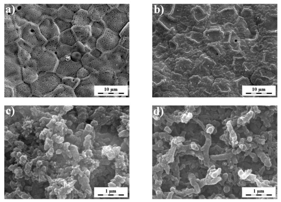
Figure 3.
Surface morphology of polymers prepared on different substrates, where the single PNR (a) and PTh (b) polymer itself are deposited on Pt, the bilayer, where PANI is deposited on PTh (c) and the three-layer, where PNR polymer is deposited on the PTh-PANI bilayer (d).
3.2.3. UV–Vis Spectrometry
UV–vis spectrometry was used as a specific method to characterize the PNR film because both forms, NR monomer, and the formed polymer (PNR), are easily soluble in DMSO, which allowed a direct comparison of UV–vis spectra. It is evident from Figure 4a that both forms exhibit two absorption bands, but their intensities are opposite. The monomer shows higher absorbance at a shorter wavelength than the polymer. Additionally, the polymer band displays a much broader bandwidth at lower wavelengths. Table 2 shows band maxima for individual spectra for clarity.
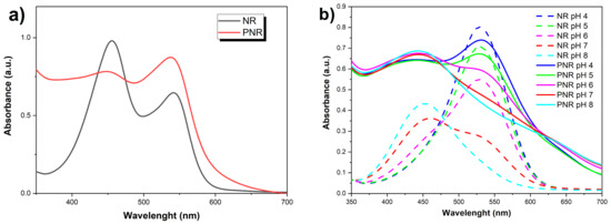
Figure 4.
Comparison of UV-vis spectra of monomer and polymer form of NR (a) dissolved in DMSO and (b) depending on the pH in 0.05 M MES solution with 0.1 M NaCl.
Table 2.
The position of absorption maxima of the UV-vis bands of the monomer and polymer NR spectra dissolved in DMSO.
Furthermore, the dependence of the absorbance of both forms (monomer and polymer) dissolved in DMSO on the pH in 0.05 M MES solution with 0.1 M NaCl was monitored (Figure 4b).
It is obvious from the spectra that, in both forms, deprotonation of the NR phenazine ring occurs with increasing pH of the solution [39,40] (Figure 5).
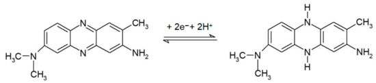
Figure 5.
Reaction scheme of NR protonation in the acidic medium [40].
A spectrum of the acidic form of NR with an absorption maximum at 530 nm (pH 4 and 5) was observed for the monomer, a spectrum of the neutral form of NR at pH 7 showing a single band at 461 nm (max) and a shoulder (marked sh) at 530 nm and the spectrum of the base form of NR (absorption maximum at λ = 453 nm; pH 8).
The spectrum of the polymer was similar, but the peaks were broader with slightly shifted maxima compared to the monomer at basic pH, which was in agreement with the literature [41], and the transition between the acidic and basic spectra occurred already at pH 6 (see Table 3).
Table 3.
Positions of band maxima of monomeric and polymeric forms of NR as a function of pH.
In our previous study, the interconnection of monomer units was hypothesized by interpreting the set of 1H-NMR and Raman spectra [7]. The newly completed study of the UV-vis spectra now leads us to the somewhat modified and detailed conclusion that NR units, next to the NH2 group, are in PNR probably dominantly connected mutually through the free position marked 6 (Figure 6a), rather than through the (positively charged) nitrogen atoms inside the phenazine ring (Figure 6b), as the protonation of the phenazine ring of the polymer is evident.
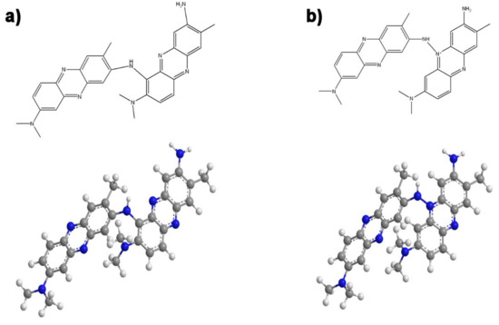
Figure 6.
Possible connection of NR units in the polymer (PNR) via the position marked 6 (a) or the nitrogen of the phenazine ring NR (b). (Molecular formulas and optimized model structures are drawn.).
3.3. Potentiometry
3.3.1. Potentiometric Response to Citrate
The prepared single, bi-, and three-layer systems were tested for citrate ions in 0.02 M TRIS medium with 0.1 M KNO3. All electrodes except bare platinum show some response to citrate ions (Figure S2 in Supplementary Materials). The determined potentiometric parameters of the electrodes (slope, concentration range, linearity, and detection limit) are shown in Table 4.
Table 4.
Evaluation of potentiometric parameter values of prepared electrodes on the concentration of citrate ions.
PTh gives a super-Nernst (−53.5 mV decade−1) response to citrate over a relatively narrow concentration range. PANI itself responds to citrates with an almost theoretical slope (−20.4 mV decade−1), but unlike the PNR electrode only in a narrower concentration range. In the bilayer formed by PTh and PNR, the influence of the underlying PTh was partially manifested, as the electrode showed a higher value of the slope than was observed for the simple PNR electrode. If the middle layer was PANI, the parameters of the PNR layer were improved (linear range, detection limit, and accuracy, Figure 7a). When switching the order of the second and third layers, i.e., for the three-layer system formed in the order PTh-PNR-PANI, no significant improvement in the response of PNR to citrates was observed. The detection limits of these multilayer electrodes are comparable to or even better than the detection limit of only PNR on platinum.
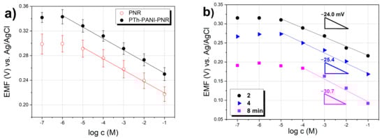
Figure 7.
Potential response of modified PNR electrodes toward citrates in TRIS buffer with KNO3 (a) comparison of PNR and three-layer electrodes (PTh-PANI-PNR), (b) influence of the thickness (deposition time) of PTh layer.
The detection limit (DL) was calculated from the intersection of two lines, namely the extrapolated linear part of the calibration line, in which the Nernst response applies with a line parallel to the x-axis and whose position on the y-axis corresponds to the potential at zero ion concentration [42].
When monitoring the effect of the preparation time of the PTh base layer on the response of the electrode from PTh-PNR, it was found that the response slope for this system increases with increasing polymerization time precisely due to the greater thickness of PTh, and at the same time as the greater thickness of PTh, the concentration range of the linear response of PNR electrodes decreases. Its considerable influence was evident here, while the change in the thickness of the underlying PTh affected the value of the initial potential (shift) of the calibration dependence of the PNR electrode on the logarithm of the citrate concentration (Figure 7b).
It is clear from these results that the properties of both outer and inner layers are important here, which was observed earlier for a two-layer system composed of PPy films containing various dopants [4,20,21]. The potentiometric response of a multilayer system is primarily conditioned by the outer layer. The participation of the inner layer is related to the permeability of the outer layer and the sensitivity of the inner layer to the tested citrate ions.
3.3.2. Potentiometric Selectivity
The potentiometric selectivity coefficient values of multilayer electrodes for carboxylic acid ions and ascorbates concerning citrates were determined by the FIM method. Only those electrodes were used that gave a response to citrates in a sufficient concentration range with an almost theoretical response, i.e., a bilayer electrode from PTh with PNR and two three-layer systems (see Figure 8).
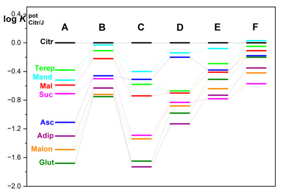
Figure 8.
Graphic representation of the potentiometric selectivity coefficients () for multilayer polymer electrodes labeled: PNR (A); PTh-PNR (B); PTh-PANI-PNR (C), PTh-PNR-PANI (D); PTh-PPy-PNR (E) and PTh-PNR-PPy (F), where the abbreviations of individual carboxylates are: Adip = adipate; Asc = ascorbate; Citr = citrate; Glut = glutarate; Mal = malate; Suc = succinate; Malon = malonate; Mand = mandelate; Terep = terephthalate.
PNR layer prepared from acetonitrile on Pt has the greatest selectivity for citrate compared to glutarate, malonate, adipate, and ascorbate (Figure 8 (electrode A)). Regarding other ions (succinate, malate, mandelate, and terephthalate) the selectivity is much lower. The use of PTh as a base material in a bilayer with PNR results in very slight changes in the order of selectivity of citrates to other anions (only the exchange of the order of (a) mandelate with terephthalate and (b) succinate with ascorbate compared to simple PNR only). Nevertheless, the selectivity for citrates is greatly reduced in this specific PTh-PNR case (Figure 8 (electrode B)).
In three-layer systems with non-specific polymers PANI and/or PPy as the outer layer [5] (Figure 8 (electrode D and F)), changes in the order of selectivity are observed, and at the same time, a significant influence of the order of applied polymers on the values of the potentiometric selectivity coefficients is evident. Moreover, when non-specific PPy is applied (as the third component) to PNR (Figure 8 (electrode E, F)), there is a great loss of selectivity of the PNR layer to citrates against almost all investigated interferents [5].
In the case of using PANI as the underlying PNR layer (Figure 8 (electrode C)), the selectivity of the electrode towards adipate, succinate, malate, and terephthalate is improved. On the contrary, this polymer system shows reduced selectivity towards malonate, ascorbate, and mandelate. In the case of swapping PANI and PNR layers, where PANI is the top layer (Figure 8 (electrode D)), there is no change in the order of selectivity, just only its rather overall reduction. In this case, stronger π-π interactions of aromatic carboxylates with conjugated non-specific polymer skeletons of thiophene, pyrrole, and aniline as well are employed. In all three-layer systems, a high affinity to the anion of ascorbic acid is also observed, which is because both PANI and PPy are redox systems in themselves, the structure of which is easily changed by the presence of redox substances in the solution [4]. The selectivity of the polymer layers to citrates and to carboxylates with different numbers of –CH2- groups (malonates –CH2-, succinate –(CH2)2-, glutarate –(CH2)3-, adipate –(CH2)4-) varies, while it also clearly depends on the non-specific polymer PTh, PANI or PPy used [5].
In general, it can be concluded that with a sufficiently thick layer of polymers that do not show sensitivity to the tested ion, the influence of the underlying platinum surface can be completely shielded, while only the response of the deposited polymer layers is employed.
3.3.3. Electrode Response and Stability
The response time of the electrodes was tested for 10−3–10−1 sodium citrate. The time to reach the terminal stable potential is in the range of 15–25 s following our previous results [17]. The response time is similar for both the simple PNR electrode and the three-layer electrode, but the potential of the multilayer electrode in citrate settled more stable. Three-layer electrodes responded to citrate anions practically immediately after immersion (see Figure S3 in Supplementary Materials).
Long-term stability of prepared single PNR and three-layer electrodes (PTh-PANI-PNR) was comparable only with low drift, except for the first few measurements, where the potential drifted several tens of mV for single PNR electrode and few mV for PTh-PANI-PNR electrode. The stability of the electrodes is predominantly influenced by the incorporation of oligomers and as well by the light rearrangement of the formed film [43]. The electrode parameters of modified electrodes (slope and concentration range) maintain unchanged during this period (not shown here).
3.3.4. Potentiometric Determination of Citrate in Soft Drinks
Potentiometric determination of citrates in real soft drinks with different citrate content (declared by the manufacturer) using PNR-modified electrodes was performed according to our previously described experimental protocol (see Section 2.4.2. Real-World Sample Analysis and ref. [17]) and the crucial calculated results are summarized in Table 5 in comparison with published data of spectrometric determination. The content of citrates in the sample was calculated based on the generally used relationship given in the literature for the standard addition method [30].
Table 5.
Determination of citrate content in g L−1 in two beverage samples using PNR electrodes by the standard addition method [30] and reference methods (Figure S4) [17,44].
The accuracy of the potentiometric determination is higher for three-layer electrodes approximately about 3% compared to simple PNR. The stability of the signal was also much better than in the case of the simple PNR electrode [17]. This observation indicates the (above-mentioned) positive effect of the PANI underlying layer, which facilitates the easier access of citrate ions to the electrode surface. In potentiometric determination, there is no need to perform complex sample treatments and the analyses are very inexpensive due to (a) the small consumption of both the sample and chemicals and (b) simple instrumentation.
4. Conclusions
Our results showed that the proposed concept of three selected and consecutively deposited polymer layers (PTh-PANI-PNR) as a sensing system is fully functional, applicable, and advantageous compared to other existing systems. The potentiometric response of the developed multilayer system was primarily influenced by the sensitive outer layer, but with some slight participation of the chemically almost inert (middle and inner) layers. In a multilayer system comprising of PTh, PANI, and PNR the order of layers and their thickness influenced the selectivity of electrodes to carboxylates. The selectivity of the PNR itself was improved by the presence of previously added polymer layers. In contrast to the simple PNR electrode, the three-layer system (PTh-PANI-PNR) improves the crucial parameters of the ion-selective electrode. Under appropriate preparation conditions, PANI supports the binding properties of PNR. Although the preparation of a multilayer PNR electrode is relatively laborious and time-consuming, the electrode modified in this way exhibits significantly better electrochemical properties than simple systems. Mainly, it is more stable, Pt surface interferences are eliminated. Moreover, the determination of citrate in a real-world sample is much more accurate. We demonstrated the successful practical application of the novel electrode as a potentiometric sensor of citrates for two real-world examples of soft drinks available on the market.
Supplementary Materials
The following supporting information can be downloaded at: https://www.mdpi.com/article/10.3390/chemosensors11030170/s1, Figure S1: An example of evaluation of detection limit and selectivity coefficient for a simple PNR electrode in citrate solutions on adipates (A); terephthalates (B) background; Figure S2: Potential response of mono-, bi- and three-layer PNR electrodes toward citrates in 0.02 M TRIS with 0.1 M KNO3; Figure S3: Time response of simple PNR and three-layer electrodes (Pth-PANI-PNR) in 0.001 M (3), 0.01 M (2) and 0.1 M (1) citrate; Figure S4: Electrophoregrams of soft drinks for citrate determination. The citrate peak is marked by the blue rectangle. References [17,30] are cited in the supplementary materials.
Author Contributions
Conceptualization, G.B.; methodology, G.B.; investigation, G.B. and P.M.; writing—original draft, G.B. and P.M.; proofreading of the manuscript, G.B., P.M. and T.V.S.; interpretation of Raman spectra, G.B. and P.M.; editing and proofreading of the manuscript G.B. and P.M.; writing—review and editing, G.B., P.M. and T.V.S. All authors have read and agreed to the published version of the manuscript.
Funding
This work was supported by a specific university study (UCT Prague, CZ, Grant Number: 402850061) from the Ministry of Education, Youth and Sports of the Czech Republic. This work was also supported by institutional resources (Department of Analytical Chemistry, UCT Prague, CZ).
Institutional Review Board Statement
Not applicable.
Informed Consent Statement
Not applicable.
Data Availability Statement
Not applicable.
Acknowledgments
The authors are grateful to J. Hromádková for her help in SEM measurement.
Conflicts of Interest
The authors declare no conflict of interest.
References
- Lukas, C.A.; Markovic, N.M.; Ross, P.N. Adsorption of halide anions at the Pt(111)-solution interface studied by in situ surface x-ray scattering. Phys. Rev. B Condens. Matter 1997, 55, 7964. [Google Scholar] [CrossRef]
- Simonet, J. Cathodic reactivity of platinum interface in the presence of tetramethylammonium salts. A pro-base cathode material? Electrochem. Commun. 2003, 5, 439–444. [Google Scholar] [CrossRef]
- Shishkanova, T.V.; Broncová, G.; Krondak, M.; Sýkora, D.; Král, V. Important aspects influencing stability of the electrochemical potential of conductive polymer-based electrodes. J. Mater. Sci. 2011, 46, 1–9. [Google Scholar] [CrossRef]
- Alumaa, A.; Hallik, A.; Mäeorg, U.; Sammelselg, V.; Tamm, J. Potentiometric properties of polypyrrole bilayers. Electrochim. Acta 2004, 49, 1767–1774. [Google Scholar] [CrossRef]
- Broncová, G.; Shishkanova, T.V.; Matějka, P.; Kubáč, D.; Král, V. Poly(Neutral Red) in Multilayer Electrode Systems. Chem. Listy 2016, 110, 800–807. [Google Scholar]
- Bobacka, J.; Ivaska, A.; Lewenstam, A. Potentiometric Ion Sensors Based on Conducting Polymers. Electroanalysis 2003, 15, 366–374. [Google Scholar] [CrossRef]
- Broncova, G.; Shishkanova, T.V.; Matejka, P.; Volf, R.; Král, V. Citrate selectivity of poly(neutral red) electropolymerized films. Anal. Chim. Acta 2004, 511, 197–205. [Google Scholar] [CrossRef]
- Inzelt, G. Conducting Polymers—A New Era in Electrochemistry, 2nd ed.; Springer: New York, NY, USA, 2012; ISBN 978-3-642-27620-0. [Google Scholar] [CrossRef]
- Broncová, G.; Shishkanova, T.V.; Krondak, M.; Volf, R.; Král, V. Potentiometric Sensors Based on Conducting Polymers: Preparation, Response Mechanisms and Applications. Chem. Listy 2009, 103, 795–799. [Google Scholar]
- Bobacka, J.; Gao, Z.; Ivaska, A. Electrochemical study on polypyrrole—poly(3-octylthiophene) bilayer films. Synth. Met. 1993, 55, 1453–1458. [Google Scholar] [CrossRef]
- Gao, Z.; Bobacka, J.; Ivaska, A. Electrochemical study of bilayer conducting polymers: Polypyrrole/polyaniline system. J. Electroanal. Chem. 1994, 364, 127–133. [Google Scholar] [CrossRef]
- Wojda, A.; Maksymiuk, K. Electrochemical properties of bilayers of conducting polymers: Polypyrrole with poly(4-styrenesulfonate) ions/poly( N-methylpyrrole). Studies of the permeability of the outer layer towards cations. J. Electroanal. Chem. 1997, 424, 93–99. [Google Scholar] [CrossRef]
- Sari, B.; Talu, M. Electrochemical copolymerization of pyrrole and aniline. Synth. Met. 1998, 94, 221–227. [Google Scholar] [CrossRef]
- Koncki, R.; Wolfbeis, O.S. Composite Films of Prussian Blue and N-Substituted Polypyrroles: Fabrication and Application to Optical Determination of pH. Anal. Chem. 1998, 70, 2544–2550. [Google Scholar] [CrossRef]
- Talu, M.; Kabasakaloglu, M.; Yildirim, F.; Sari, B. Electrochemical synthesis and characterization of homopolymers of polyfuran and polythiophene and bipolymer films polyfuran/polythiophene and polythiophene/polyfuran. Appl. Surf. Sci. 2001, 181, 51–60. [Google Scholar] [CrossRef]
- Shishkanova, T.V.; Sapurina, I.; Stejskal, J.; Král, V.; Volf, R. Ion-selective electrodes: Polyaniline modification and anion recognition. Anal. Chim. Acta 2005, 553, 160–168. [Google Scholar] [CrossRef]
- Broncová, G.; Shishkanova, T.V.; Krondak, M.; Volf, R.; Král, V. Optimalization of Poly(neutral red) Coated-wire Electrode for Determination of Citrate in Soft Drinks. Sensors 2008, 8, 594–606. [Google Scholar] [CrossRef]
- Baluchová, S.; Barek, J.; Tomé, L.I.N.; Brett, C.M.A.; Schwarzová-Pecková, K. Vanillylmandelic and Homovanillic acid: Electroanalysis at non-modified and polymer-modified carbon-based electrodes. J. Electroanal. Chem. 2018, 821, 22–32. [Google Scholar] [CrossRef]
- Leidner, C.R.; Denisevich, P.; Willman, K.W.; Murray, R.W. Charge trapping reactions in bilayer electrodes. J. Electroanal. Chem. 1984, 164, 63–78. [Google Scholar] [CrossRef]
- Ren, X.; Pickup, P.G. Impedance of Polypyrrole Perchlorate/Polypyrrole Poly(styrenesulfonate) Bilayer. J. Phys. Chem. 1993, 97, 3941–3943. [Google Scholar] [CrossRef]
- Wojda, A.; Maksymiuk, K. Potentiometric studies of bilayers of conducting polymers. J. Electroanal. Chem. 1998, 441, 205–214. [Google Scholar] [CrossRef]
- Mangold, K.-M.; Schäfer, S.; Jüttner, K. Reference electrodes based on conducting polymer bilayers. Synth. Met. 2001, 119, 345–346. [Google Scholar] [CrossRef]
- Weng, S.; Zhou, J.; Lin, Z. Preparation of one-dimensional (1D) polyaniline–polypyrrole coaxial nanofibers and their application in gas sensor. Synth. Met. 2010, 160, 1136–1142. [Google Scholar] [CrossRef]
- Stejskal, J.; Sapurina, I.; Trchová, M.; Šeděnková, I.; Kovářová, J.; Kopecká, J.; Prokeš, J. Coaxial conducting polymer nanotubes: Polypyrrole nanotubes coated with polyaniline or poly(p-phenylenediamine) and products of their carbonization. Chem. Pap. 2015, 69, 1341–1349. [Google Scholar] [CrossRef]
- Valaski, R.; Ayoub, S.; Micaroni, L.; Hümmelgen, I.A. Polypyrrole-poly(3-methylthiophene) bilayer films electrochemically deposited onto tin oxide. J. Solid State Electrochem. 2002, 6, 231–236. [Google Scholar] [CrossRef]
- Volf, R.; Král, V.; Hrdlička, J.; Shishkanova, T.V.; Broncová, G.; Krondak, M.; Stastný, M.; Kroulík, J.; Valík, M.; Matějka, P.; et al. Preparation, characterization and analytical application of electropolymerized films. Solid State Ionics 2002, 57, 154–155. [Google Scholar] [CrossRef]
- Záruba, K.; Matějka, P.; Volf, R.; Volka, K.; Král, V.; Sessler, J.L. Formation of Porphyrin- and Sapphyrin-Containing Monolayers on Electrochemically Prepared Gold Substrates: A FT Raman Spectroscopic Study. Langmuir 2002, 18, 6896–6906. [Google Scholar] [CrossRef]
- Březnová, H.; Volf, R.; Král, V.; Sessler, J.L.; Try, A.C.; Shishkanova, T.V. Monomer and polymer quinoxaline derivatives for cationic recognition. Anal. Bioanal. Chem. 2003, 375, 1193–1198. [Google Scholar] [CrossRef]
- Umezawa, Y.; Bühlmann, P.; Umezawa, K.; Tohda, K.; Amemiya, S. Potentiometric selectivity coefficients of ion-selective electrodes. Part I. Pure Appl. Chem. 2000, 72, 1851–2082. [Google Scholar] [CrossRef]
- Koryta, J.; Štulík, K. Iontově-Selektivní Elektrody (Ion-Selective Electrode); Academia: Prague, Czech, 1984; ISBN 21-035-84. [Google Scholar]
- Udum, A.Y.; Pekmez, K.; Yildiz, A. Electropolymerization of self-doped polythiophene in acetonitrile containing FSO3H. Synth. Met. 2004, 142, 7–12. [Google Scholar] [CrossRef]
- Choi, S.-J.; Park, S.-M. Electrochemistry of Conductive Polymers. XXVI. Effects of Electrolytes and Growth Methods on Polyaniline Morphology. J. Electrochem. Soc. 2002, 149, E26–E34. [Google Scholar] [CrossRef]
- Pandey, P.C.; Singh, G. Tetraphenylborate doped polyaniline based novel pH sensor and solid-state urea biosensor. Talanta 2001, 55, 773–782. [Google Scholar] [CrossRef]
- Sulimenko, T.; Stejskal, J.; Křivka, I.; Prokeš, J. Conductivity of colloidal polyaniline dispersions. Eur. Polym. J. 2001, 37, 219–226. [Google Scholar] [CrossRef]
- He, J.; Zhou, H.; Wan, F.; Lu, F.; Xue, G. SERS study of the high quality conducting polythiophene film. Vib. Spectrosc. 2003, 31, 265–269. [Google Scholar] [CrossRef]
- Karakisla, M.; Aksu, L.; Sacak, M. Polypyrrole/polyaniline conductive films obtained electrochemically on polycarbonate-coated platinum electrodes. Polym. Int. 2002, 51, 1371–1377. [Google Scholar] [CrossRef]
- Berrada, K.; Quillard, S.; Louam, G.; Lefrant, S. Polyanilines and substituted polyanilines: A comparative study of the Raman spectra of leucoemeraldine, emeraldine and pernigraniline. Synth. Met. 1995, 69, 201–204. [Google Scholar] [CrossRef]
- Baibarac, M.; Cochet, M.; Lapkowski, M.; Mihut, L.; Lefrant, S.; Baltog, I. SERS spectra of polyaniline thin films deposited on rough Ag, Au and Cu. Polymer film thickness and roughness parameter dependence of SERS spectra. Synth. Met. 1998, 96, 63–70. [Google Scholar] [CrossRef]
- Benito, D.; Gabrielli, C.; García-Jareño, J.J.; Keddam, M.; Perrot, H.; Vicente, F. An electrochemical impedance and ac-electrogravimetry study of PNR films in aqueous salt media. Electrochem. Commun. 2002, 4, 613–619. [Google Scholar] [CrossRef]
- Saez, E.I.; Corn, R.M. In situ polarization modulation—Fourier transform infrared spectroelectrochemistry of phenazine and phenothiazine dye films at polycrystalline gold electrodes. Electrochim. Acta 1993, 38, 1619–1625. [Google Scholar] [CrossRef]
- Schlereth, D.D.; Karyakin, A.A. Electropolymerization of phenothiazine, phenoxazine and phenazine derivatives: Characterization of the polymers by UV-visible difference spectroelectrochemistry and Fourier transform IR spectroscopy. J. Electroanal. Chem. 1995, 395, 221–232. [Google Scholar] [CrossRef]
- Lindner, E.; Umeyawa, Y. Performance evaluation criteria for preparation and measurement of macro- and microfabricated ion-selective electrodes (IUPAC Technical Report) Pure. Appl. Chem. 2008, 80, 85–104. [Google Scholar] [CrossRef]
- Mousavi, Z.; Bobacka, J.; Lewenstam, A.; Ivaska, A. Response mechanism of potentiometric Ag+ sensor based on PEDOT doped with silver hexabromocarborane. J. Electroanal. Chem. 2006, 593, 219–226. [Google Scholar] [CrossRef]
- Wiskur, S.L.; Ait-Haddou, H.; Lavigne, J.J.; Anslyn, E.V. Teaching Old Indicators New Tricks. Acc. Chem. Res. 2001, 34, 963–972. [Google Scholar] [CrossRef] [PubMed]


Disclaimer/Publisher’s Note: The statements, opinions and data contained in all publications are solely those of the individual author(s) and contributor(s) and not of MDPI and/or the editor(s). MDPI and/or the editor(s) disclaim responsibility for any injury to people or property resulting from any ideas, methods, instructions or products referred to in the content. |
© 2023 by the authors. Licensee MDPI, Basel, Switzerland. This article is an open access article distributed under the terms and conditions of the Creative Commons Attribution (CC BY) license (https://creativecommons.org/licenses/by/4.0/).