Article

Enhanced Gas Detection by Altering Gate Voltage Polarity of Polypyrrole/Graphene Field-Effect Transistor Sensor

1
Institute of Information and Communication Technologies, Electronics and Applied Mathematics (ICTEAM), Université Catholique de Louvain (UCLouvain), Place du Levant, 3, 1348 Louvain-la-Neuve, Belgium
2
Institute of Condensed Matter and Nanosciences/Nanoscopic Physics (IMCN/NAPS), Université Catholique de Louvain (UCLouvain), Chemin du Cyclotron 2, 1348 Louvain-la-Neuve, Belgium
3
Materia Nova ASBL, 3, Avenue N. Copernic, 7000 Mons, Belgium
4
Materials Science Department, University of Mons, 56, Rue de l’Epargne, 7000 Mons, Belgium
*
Author to whom correspondence should be addressed.
Chemosensors 2022, 10(11), 467; https://doi.org/10.3390/chemosensors10110467
Submission received: 5 October 2022 / Revised: 28 October 2022 / Accepted: 4 November 2022 / Published: 9 November 2022

Abstract

:
This work introduces a new measurement methodology for enhancing gas detection by tuning the magnitude and polarity of back-gate voltage of a field-effect transistor (FET)-based sensor. The aim is to simultaneously strengthen the sensor response and accelerate the sensor recovery. In addition, this methodology can consume less energy compared with conventional measurements by direct current bias. To illustrate the benefits of the proposed methodology, we fabricated and characterized a polypyrrole/graphene (PPy/G) FET sensor for ammonia (NH3) detection. Our experiment, simulation and calculation results demonstrated that the redox reaction between the NH3 molecules and the PPy/G sensitive layer could be controlled by altering the polarity and the magnitude of the back-gate voltage. This proof-of-principle measurement methodology, which solves the inherent contradiction between high response and slow recovery of the chemiresistive sensor, could be extended to detect other gases, so as to improve global gas measurement systems. It opens up a new route for FET-based gas sensors in practical applications.

1. Introduction

The chemiresistive sensor (or chemiresistor) with two electrodes is the most common gas sensor. Its working principle is to detect gas concentration by measuring the current or resistance change caused by charge transfer between the target gas molecules and the sensitive layers. Such a measurement is implemented by continuously monitoring the current between two electrodes under a given direct current (DC) voltage. Another configuration for gas detection is based on the field-effect transistor (FET), which is a three-terminal device. The sensitive layer, which acts as the FET channel, lies between the source and the drain terminals and is insulated from the back gate by a dielectric layer. The drain current, flowing along the sensitive layer, can be modulated by the back-gate voltage. The drain current can also be changed by the electrons donated/withdrawn from the target gas molecules. During the sensing measurement of an FET-based sensor, the source is usually grounded, the drain is continuously biased with a given DC voltage, and the back gate is swept by DC voltages. The detection of the gas concentration depends on the drain current change caused by the charge transfer. Compared with the chemiresistor, the FET sensor is regarded as highly sensitive with good selectivity [1,2], due to its ability to deliver multi-parameter responses, such as the following: drain current, charge mobility, threshold voltage, flat-band voltage, work function, and on/off current ratio [3,4].
The working principles of both types of sensors are based on the current change measured via a DC voltage [5]. The biggest issue of the DC measurement is the slow response/recovery [6,7], and the current baseline drift [8], designated as “poisoning effect”. The charge transfer is a slow chemical procedure, generally of the order of tens to thousands of seconds. This chemical procedure is more efficient for adsorbed molecules with large binding energy [9]. More particularly, the charge transfer between adsorbed gas molecules and interface traps/defect sites are extremely slow [10,11]. These slow dynamic processes limit the sensor response and recovery speeds. Moreover, the stronger the interaction between adsorbed molecules and the sensitive layer, the higher the sensitivity to the gas, but the slower the recovery [12]. To overcome these problems, various technologies and methods have been proposed, such as heating [13,14], micro-hotplate [15], ultraviolet radiation [16], current stimulation [17], voltage bias [18], degassing [19], or chemo-selective coating [20]. However, all these solutions result in complex fabrication processes, increased energy consumption, high production costs, and bulky device sizes.
Kulkarni’s group [21] developed a heterodyne sensor, in which an alternating current (AC) was applied to the source of a graphene FET sensor to modulate the channel charge carriers and, simultaneously, to excite the perturbation of target molecular dipoles. They used the heterodyne mixing current as the sensing signal to detect the gas concentration. The signal parameters can be phase, amplitude, or frequency of the mixing current. These parameters contain rich information on the target molecules. The heterodyne sensor obtained a detection limit of 1 ppb and a response time of 0.1 s. However, heterodyne sensing can only be used for the detection of polar gases. Recently, Liu’s group [22] gated a graphene FET sensor by an AC voltage so as to limit the slow interaction between the adsorbed molecules and surface traps/defect states. Their technique depends on the phase lag between the channel current and the AC gate voltage to determine gas concentrations. For detecting water, methanol and ethanol vapors, they obtained a minimal baseline drift and a recovery speed that was ten times faster than that in the conventional DC measurement. Although slow interaction was excluded by this technique, it might be difficult for the sensor sensitivity to reach an ultra-high level. Indeed, the phase signal measurement only responds to weak adsorption and desorption of gas molecules above a certain distance from the graphene surface.
The objective of the present work is to introduce a new measurement methodology for gas detection, using FET-based sensors. By alternating the polarity and the magnitude of the back-gate voltage, the present method can not only enhance sensor response, but can also speed up sensor recovery.

2. Materials and Methods

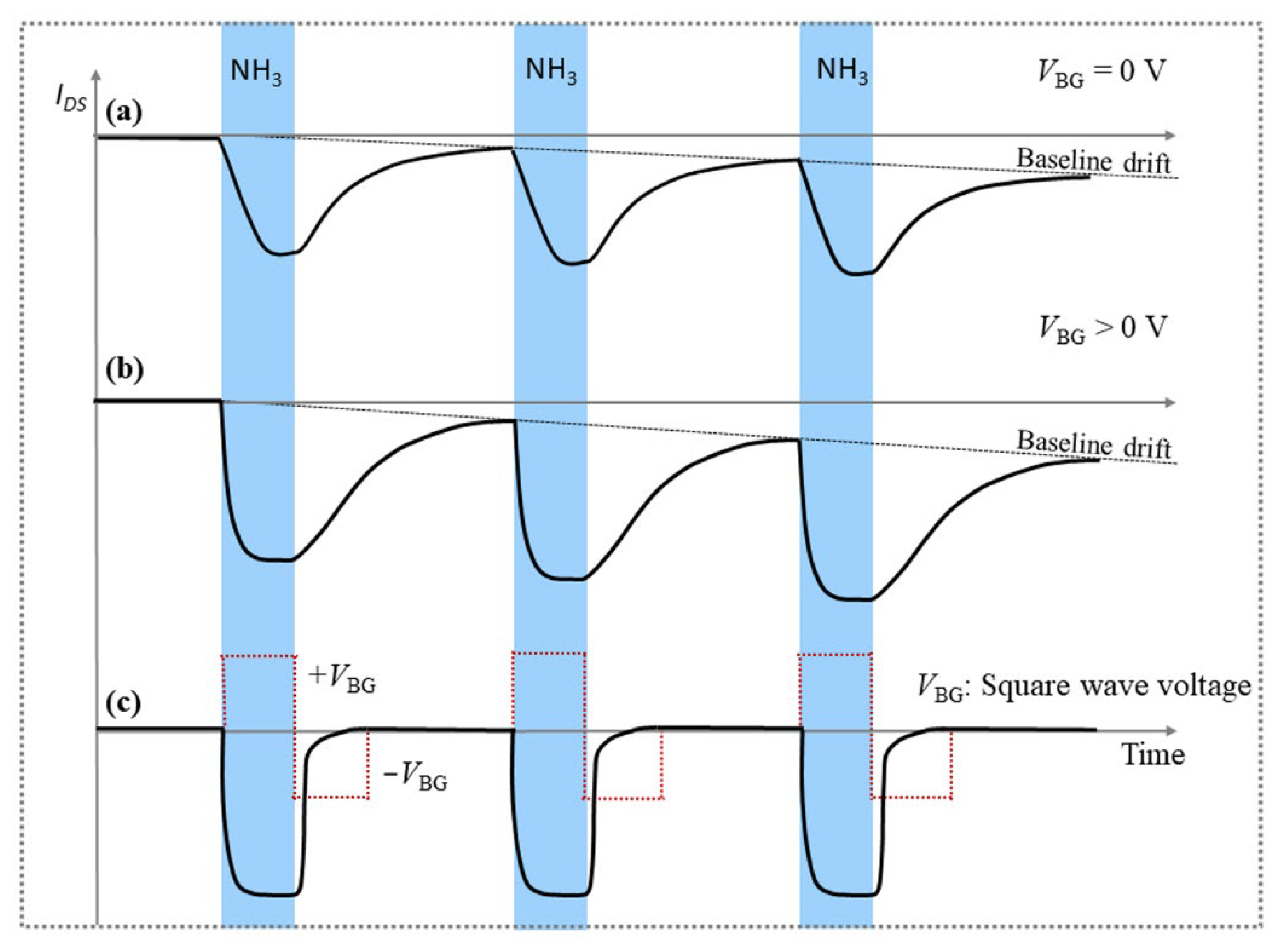
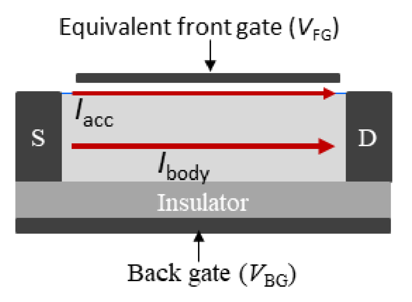
2.1. Measurement Principle

The measurement principle of the present methodology is attributed to the redox reaction between a target gas and a sensitive layer, controlled by the electric-field effect. In order to clearly explain the measurement principle of the novel methodology, we focus our attention on a polypyrrole/graphene (PPy/G) FET sensor for ammonia (NH3) detection. Hereafter, we limit our explanation and analysis to an accumulation-mode p-channel transistor. The current flow in this transistor is due to hole transport in the p-channel. The target gas could be any electron-donating gas (i.e., a reducing gas), such as NH3, H2, CH4, H2S, CO, etc. It could also be any electron-accepting gas (i.e., an oxidizing gas), like NO2, H2O, O2, CO2, SO2, etc. Note that the description of the accumulation-mode n-channel transistor can readily be derived from the description of the accumulation-mode p-channel transistor by appropriately changing sign of the electric field. In general, both graphene and polypyrrole have p-type doping. As explained below, NH3 molecules mainly adsorb on the PPy surface, while the role of graphene is to improve the charge collection towards the source and drain of the sensor. Graphene also plays a critical role in the deposition of the PPy layer (i.e., graphene acts as a support substrate and electrode during the electropolymerization process). It is important to note that the floating graphene has no screening effect on the electric field created by the back-gate voltage.
Figure 1 shows the schematic cross-sections of the PPy/G FET sensor, and Figure 2 schematically plots the drain current (IDS) response of the PPy/G FET sensor for NH3 detection under different polarities and values of the back-gate voltages. When the back gate of the PPy/G FET sensor is grounded (VBG = 0 V), the behavior of the sensor is similar to a chemiresistor (Figure 1a). When the electron-donating gas molecules (such as NH3) adsorb onto the PPy channel surface, electrons are transferred from NH3 to the π backbone of the PPy. They neutralize holes in the p-type PPy, thereby, decreasing the current in the PPy channel (Figure 1b). For desorption in the NH3-off state, the electrons go back to the NH3 from the PPy channel and, then, the neutralized PPy reverts back to p-type, restoring the PPy channel current to its original value. However, this is a slow chemical procedure, which may not even result in complete restoration at room temperature (Figure 1c). It can be seen from Figure 2a that the recovery time of the sensor was long and the response curve of the sensor current looks like a shark-fin with a baseline drift.
In Figure 1d, the back gate of the PPy/G FET sensor is biased by a positive voltage (VBG > 0 V). Holes are, therefore, pushed to the PPy channel surface, which facilitates PPy accepting more electrons from NH3. As a result, the current in the PPy channel significantly decrease. When the sensor is exposed to NH3, the redox reaction between NH3 and PPy is described by the following:
NH3 (g) + PPy ↔ PPy-NH3
PPy-NH3 + h+ ↔ PPy-NH3+
In reaction (1), the electron-donating NH3 molecules first react with PPy to form PPy-NH3 complexes. With holes (h+), the PPy-NH3 complexes then become positively charged ions (PPy-NH3+) in reaction (2). The surface hole concentration can be modulated by the value of the back-gate voltage. Therefore, the number of the PPy-NH3+ ions are increased by positive back-gate voltage. As a result, the increased PPy-NH3+ ions are prone to adsorb many more electrons from the NH3 molecules onto the PPy surface, thereby strengthening PPy chemical reduction and strongly decreasing sensor current (Figure 1e). In other words, when the PPy channel is exposed to electron-donating NH3 molecules under positive back-gate voltage, many more NH3 molecules and NH3-donating electrons (reactions (1) and (2) in the forward direction) can be attracted, strongly increasing the sensor response. This is equivalent to an amplification effect, being created by the back-gate voltage. However, the desorption of NH3 molecules is quite slow under positive gate voltage (Figure 1f). As shown in Figure 2b, the current response of the sensor changes into a larger shark-fin curve, with a larger baseline drift, and the sensor recovery time slows down. Although the sensor response is higher at VBG > 0 V than at VBG = 0 V, sensor recovery becomes problematic at VBG > 0 V. The larger the back-gate voltage, the longer the full recovery time. The reason is that some NH3 molecules and NH3-donating electrons cannot easily leave the PPy channel surface since they have been attracted by (or recombined with) a number of holes under VBG > 0 V.
To solve this problem, a negative voltage is applied to the back gate (VBG < 0 V) and this withdraws holes from the PPy surface, as shown in Figure 1g. The PPy-NH3+ ions decompose back into NH3 and PPy (reactions (1) and (2) in the reverse direction), accelerates sensor current recovery. This means that the negative back-gate voltage helps electrons to move back to the NH3 molecules. It is important to note that when applying a negative back-gate voltage, the following different situations may occur: (i) The channel current may turn back to its initial value (IDS0). This happens when the number of holes withdrawn by the negative back-gate voltage equals the number of NH3-donating electrons. (ii) The channel current may be larger/smaller than IDS0. This happens when the withdrawn holes are less/more in number as compared to the number of donated electrons. Full recovery of the channel current to IDS0 is achieved within the first (ideal) case. This case happens by tuning the negative back-gate voltage to a value at which the drain current turns back to its initial value (IDS0) in the NH3-off state.
According to the phenomena described above, we developed a new measurement methodology, in which different polarity voltages (such as a square wave voltage) were provided to the back gate of the FET sensor during the sensing measurement (Figure 2c). Hereafter, the NH3-on state meant that NH3 was injected into the testing chamber, while the NH3-off state meant that NH3 was switched off in the testing chamber. In the NH3-on state, the positive half cycle of the square wave voltage (+VBG) pushed holes to the PPy channel surface. This promoted PPy chemical reduction, and significantly increased the sensor current response. In the NH3-off state, the negative half cycle of the square wave voltage (−VBG) withdrew holes from the PPy channel surface. This boosted PPy chemical oxidation and, thus, accelerated the sensor recovery. The square wave voltage changed the response profile of the sensor current from a shark-fin curve (Figure 2a,b) to a nearly rectangular curve (Figure 2c). In other words, the redox reaction between NH3 and PPy could be controlled by the square wave voltage. In brief, it is possible to increase the current response of the sensor and reduce the recovery time of the sensor by using the positive and negative half cycles of the square wave voltage, respectively.
DC measurements often require a tradeoff between having a thicker sensitive layer, allowing for higher sensitivity, or a thinner sensitive layer, allowing for quicker recovery. The need for a tradeoff can be easily solved in an FET sensor gated by different polarity voltages. This is the great advantage of our methodology over the common methods used in DC measurements conducted by FET sensors.

2.2. Measurement Setup

Figure 3 schematically displays the experimental setup proposed in this work for the sensing measurements. This setup is composed of a PPy/G FET gas sensor, a square wave generator, a current detector and a signal processor. The square wave generator is electrically connected to the back gate of the FET gas sensor to maximize the sensor response, and to accelerate the sensor recovery, for target gases. The current detector, connected between the source and drain of the FET sensor, monitors the modulated currents containing the gas concentration information during the sensing procedure. The signal processor is configured to communicate the information between the square wave generator and the current detector. The signal processor can control the starting time, the amplitude, the polarity and the period of the square wave voltage, according to the feedback signal from the current detector. Specifically, the current detector informs the signal processor when the drain current experiences a change. For example, when a p-type FET sensor is exposed to electron-donating gas and its drain current decreases, the generator applies positive voltage to the sensor back gate, which boosts the polymer reduction reaction and significantly enhances the sensor response (amplification effect). When the electron-donating gas is switched off and the drain current increases, the generator offers negative voltage to the sensor back gate, which promotes the polymer oxidation reaction and accelerates the sensor recovery. In addition, the square wave voltage can be used to evaluate the repeatability of the sensor.

2.3. Sensor Fabrication and Measurement

The fabrication details of the PPy/G FET gas sensor can be found in our previous works [23,24]. Briefly, the fabrication process includes the following four simple steps: (i) The Au interdigitated electrodes (IDEs), or a pair of electrode pads, were prepared on a SiO2/Si substrate by the lift-off process. The SiO2 thickness was 90 or 300 nm to allow easy observation of graphene with an optical microscope; (ii) The Al back-gate electrode (300 nm in thickness) was formed on the back of the SiO2/Si substrate by electron-beam physical vapor deposition; (iii) Small-sized graphene oxide was deposited on top of the IDEs by the ultrasonic spray pyrolysis technique, while large-sized CVD graphene was transferred to the top of the electrode pads using poly(methyl methacrylate) as the supporting film; (iv) A thin layer of PPy was synthesized on the graphene surface by electropolymerization. This step was carried out at 20 °C in an electropolymerization bath, which included a solution of pyrrole (0.35 mL) and NaClO4 (0.6 g) in acetonitrile (50 mL). The graphene on the substrate was used as the working electrode. The counter and reference electrodes were made of Pt and Ag/AgCl, respectively [25]. When a voltage pulse was applied to the working electrode, the PPy layer was synthesized on the graphene surface. The PPy synthesis ratio was 10 nm/cycle under a voltage pulse of 0.9 V. The samples were then washed with ethanol. Here, the PPy/G sensitive layer acted as the channel of the FET sensor and was exposed to NH3, while the IDEs, or electrode pads, acted as the source/drain of the FET sensor. Our sensor structure is simpler, compared with the real FET device, since it omits the source/drain doping step.
Sensor measurements were carried out in a testing chamber with an internal volume of 42 cm3 (3 cm × 3.5 cm × 4 cm) at atmospheric pressure, with a temperature of 20 °C. Wet air (relative humidity of 50% RH) and NH3 were used as carrier gas and target gas, respectively. The gas flow in the testing chamber was the piston mode. The desired NH3 concentration was obtained by dilution of 100 ppm NH3 with wet air. For 1 ppm NH3 concentration, we mixed 10 mL/min of 100 ppm NH3 in air with 490 mL/min of dry air and 500 mL/min of saturated wet air (100% RH). The total gas flow rate in the testing chamber was always kept at 1000 mL/min.

3. Results and Discussion

3.1. Experiment Results

The fabricated PPy/G FET sensors were used to experimentally analyze the benefits of the measurement methodology proposed in this work. In order to clearly observe the influence of the electric-field effect on the response and recovery of the sensors, we examined the IDS variation of the sensors for detecting 1 ppm NH3 under different values and polarities of VBG. The IDS measurements were performed at VDS = −0.8 V and the source grounded. We used rectangular pulses for the ammonia injection. The examinations were carried out at room temperature and relative humidity of 50%.
Figure 4a shows the drain current/back-gate voltage characteristics for a fabricated PPy/G FET sensor in the absence of NH3. It confirms that this sensor was a typical accumulation-mode p-channel transistor. In the NH3-off state, the drain current increased with positive back-gate voltage, since holes were pushed to the PPy surface, which enhanced the carrier density of the p-channel. In the NH3-on state, the drain current decreased with positive back-gate voltage since the pushed holes on the PPy surface were neutralized by the NH3-donated electrons, reducing the carrier density of the p-channel. Figure 4b experimentally records the IDS response of the PPy/G FET sensor under different back-gate voltage (VBG). In Figure 4b, the vertical blue rectangles indicate the period of 1 ppm NH3 injection in the testing chamber (the NH3-on state) and the red line indicates the values and polarities of the back-gate voltages. In region AD, the back gate of the sensor was grounded (VBG = 0 V). In region BC, where the sensor was exposed to NH3, no significant current response was observed. In region DE, the back gate was biased at VBG = +10 V and IDS decreased with time until it reached a plateau. The sensor showed a current response of 16%. We defined the current response as (IDS0 − IDS)/IDS0, where IDS0 is the initial current at VBG = 0 V in the NH3-off state and IDS is the minimum current at VBG = 10 V in the NH3-on state. This indicated that positive back-gate voltage really strengthened the sensor response. However, IDS did not recover to its original value (IDS0) in region EF for the NH3-off state. This might have been due to the fact that the NH3-donating electrons were trapped in the defect states of the sensitive layer, and, thus, the withdrawing of these electrons was very slow (difficult). Then, a larger VBG = +30 V was applied to the back gate in region FJ. For the NH3-on state in region FH, a larger current response of 21% was obtained. This confirmed that the larger the positive back-gate voltage, the larger the response of the sensor current. A larger positive voltage produced a stronger electric field to force more holes to the PPy surface. This provided more opportunity for the reaction between NH3 and PPy to be completed. For the NH3-off state in region HI, IDS could not completely return to IDS0, since the current curve tended to a plateau in this region. Moreover, the sensor recovery was slower at VBG = +30 V (recovery started at point H) than at VBG = +10 V (recovery started at point E). At point I, a negative voltage (VBG = −30 V) was provided to the back gate and the sensor recovery became much faster. Namely, the recovery time was less than 10 s from point I to J. This proved the fact that the negative back-gate voltage accelerated the sensor recovery. The reason for this in the physics context can be found in Section 2.1 (measurement principle). Briefly, the negative back-gate voltage withdrew holes from the PPy surface, which caused the donated electrons to quickly return back to the NH3 molecules. However, if the absolute value of the negative voltage was too large, the quantity of holes was higher than the quantity of donated electrons and, then, IDS had a value higher than IDS0, as shown at point K. We performed this examination with several PPy/G FET sensors and obtained similar current response trends. The advantages of our measurement methodology were well reflected in the results of the experiments. They are expressed by the simulation results and the calculations in analytical modeling below.
The present measurements were performed manually. In the future, we intend to automatize the measurements by using a signal processor, as described in Section 2.2. In the real measurements, the NH3 injection might not be a perfect pulse and, thus, the drain current (IDS) change might fluctuate. However, IDS always tends to decrease in the NH3-on state, while IDS always tends to increase in the NH3-off state. Therefore, we may set an a priori threshold current (Ith) for an automatic measurement. When IDS, measured by the current detector, reaches Ith (indicating the NH3-on state), the signal processor automatically switches on the square wave generator and applies a positive half cycle of the square wave voltage (VBG > 0 V) to the back gate at point D. The signal processor tracks, in real-time, changes in the IDS during exposure to NH3. When IDS is larger than Ith (indicating the NH3–off state), the signal processor automatically switches the positive half cycle to the negative half cycle of the square wave (VBG < 0 V) at point E, causing IDS to quickly increase to IDS0. In this case, the positive half cycle of the square wave pushes holes to the PPy surface and increases the sensor response, while the negative half cycle of the square wave quickly withdraws holes from the PPy surface and accelerates the sensor recovery. Under a square wave voltage, the sensor shows a high response and a rapid recovery for NH3 detection at room temperature.
As discussed above, the redox reaction of PPy with NH3 plays an important role. However, graphene not only serves as a support material for electropolymerization, but also accelerates the electron transport between the source and drain, shortening the response/recovery times. Under the electric-field induction, the electrons donated by NH3 may pass through the PPy to react with the sp2-bonded carbon atoms of graphene. This synergistic effect may intensify the sensor sensitivity. Moreover, the low contact resistance of graphene with Au electrodes would result in a high signal/noise ratio and low energy consumption.

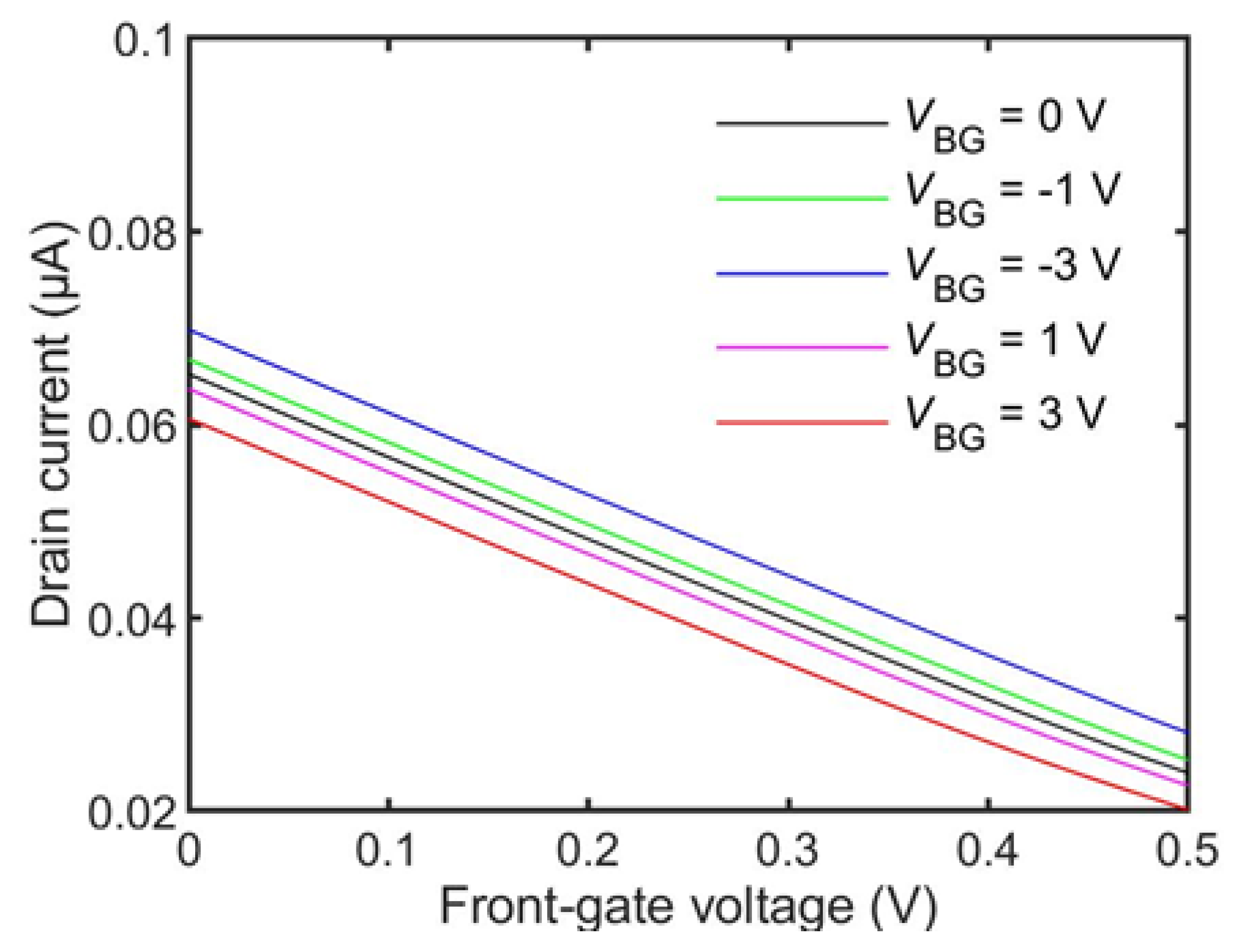
3.2. Simulation Results

Using the ATLAS software from SILVACO, we simulated the IDS response of the PPy/G FET sensor in detecting electron-donating gases under different VBG. The 2D simulation is based on an accumulation-mode p-channel transistor, the channel of which is made of thin polymer film. In this kind of transistor, holes are responsible for the current flow, which is similar to the behavior of our p-type PPy/graphene sensor. The important physical parameters used in the present simulation are listed in Table 1. A 100-nm thick p-type polymer was used to mimic the PPy/G sensitive layer. The channel length of the transistor was 2 µm, which was the same as the inter-finger distance in the PPy/G gas sensor. The source/drain without doping was directly in contact with Au electrodes. The length of each Au electrode was 0.5 µm. The transistor had a back-gate electrode and the thickness of the back-gate oxide was 300 nm. The length of the back gate was 3 µm, and it overlapped the source, channel and drain.
As already mentioned, the electron-donating gas was equivalent to a positive voltage applied on the front-gate of the accumulation-mode p-channel transistor. Therefore, we used a front-gate electrode to induce the donated electrons by electrostatic doping [26]. The IDS change caused by electron transfer from NH3 to the sensitive layer could be computed and demonstrated with the ATLAS software. The simulation was performed as follows. We first extracted IDS0 in the NH3-off state when VBG and VFG equaled zero. Then, IDS for VFG = +0.1 V and VFG = 0 V were set as the current corresponding to the NH3-on state and the NH3-off state, respectively. Finally, with VFG fixed at +0.1 V, we simulated the IDS variations by changing VBG. The simulation was carried out at VDS = −0.8 V.
Figure 5 demonstrates the simulation results, which show the IDS response of the accumulation-mode polymer p-type channel transistor versus time at different VBG for the electron-donating gas on/off states. The simulation results are presented by following the experimental route as shown in Figure 4. We first kept VFG = 0 V (in the gas-off state) and VBG = 0 V to simulate the initial value of the drain current (IDS0) in region AB. Region BC at VBG = 0 V shows the IDS variations by switching VFG from 0 to +0.1 V and +0.1 to 0 V to emulate the electron-donating gas-on state and gas-off state, respectively. The transistor exhibited an IDS decrease of 43% at VBG = 0 V when the gas was on. In region CD, the transistor was reset to IDS0 by switching VFG = 0 V and VBG = 0 V. Then, we applied VBG = +1 V to the transistor in the gas-on state (VFG = +0.1 V) to simulate the IDS variations. In this case, a change of 92% in IDS was obtained. Further, we increased VBG from +1 to +3 V in the gas-on state (in region FH). A larger change (>100%) in IDS appeared. The IDS response of the transistor was twice as high at VBG = 3 V as it was at VBG = 1 V. It was clear that the IDS response of the transistor increased with a positive VBG. However, the IDS recovery of the transistor was slow and even incomplete under positive VBG (in region HI). This issue was solved by applying a negative voltage to the back gate. When VBG = −3 V, IDS increased sharply and even exceeded IDS0 (in region JK). The IDS profile in Figure 5 is qualitatively consistent with the experimental result shown in Figure 4. This confirmed the sensing mechanism proposed in the previous section.

3.3. Calculation Results Based on a Sensor Modeling

Figure 6 shows the schematic cross-section of an accumulation-mode p-channel thin film transistor, which was used to model the behavior of the PPy/G FET sensor. In our modeling, the electron transfer behavior between the target gas and the sensitive layer was equivalent to the application of a front-gate voltage (VFG). In other words, the donated electrons in the p-channel were induced by “electrostatic doping” [27]. When a negative drain voltage (VDS) was applied to the FET sensor, the drain current flowing through the PPy thin film (IDS) was the sum of two contributions: a surface accumulation channel (Iacc) and a body current (Ibody):
IDS = Ibody + Iacc
In the thin film configuration, the drain current could be modified by VFG (the front-gate voltage) and VBG (the back-gate voltage). NH3 is an electron-donating gas. Therefore, it was equivalent to applying a positive VFG to the front gate of the thin film transistor. In this case, the drain current could be modulated not only by the gas concentrations (altering VFG), but also by VBG.
We adapted Colinge’s modeling of the thin-film accumulation-mode silicon-on-insulator p-channel MOSFET [28] to a polymer channel, and then calculated IDS as a function of VFG for different values of VBG. The parameters used in our calculation were as follows: polymer channel length, width and thickness were 2, 1, and 0.1 µm, respectively; thicknesses of the front-gate oxide and back-gate oxide were 1 and 90 nm, respectively; charge densities of the top and bottom interfaces were 5 × 10¹⁰ and 1011 cm−2, respectively; doping concentration of the PPy channel was set to 4.5 × 10¹⁸ atoms/cm3; hole mobility in the PPy body was 0.1 cm2/Vs; PPy band gap was 2.32 eV [29]; PPy permittivity was 500 [30]; drain voltage VDS was fixed at −0.8 V.
Figure 7 presents the calculation results based on the analytical modeling in ref. [28]. It is clear that for a given VFG (i.e., for a given NH3 concentration), IDS increased and decreased by applying negative and positive VBG, respectively. Moreover, the larger the absolute value of VBG, the larger the IDS change. These results theoretically supported the sensing mechanism mentioned above. This model was also suitable for electron-accepting gases, simply by changing the sign of the front-gate voltage. Our calculation results were also consistent with the steady-state linear behavior of accumulation-mode long-channel p-MOSFET [31].

4. Conclusions

We developed a new measurement methodology for enhancing gas detection by tuning the magnitude and polarity of back-gate voltage of a field-effect transistor (FET)-based sensor. A polypyrrole (PPy)/graphene FET sensor was used to examine the proposed measurement methodology for detecting an electron-donating gas (NH3). Our experimental results, supported by analytic modeling and ATLAS 2D simulation, demonstrated that the redox reaction of the PPy sensitive layer with NH3 molecules was controlled by the back-gate voltage polarity and value of the FET sensor. Positive back-gate voltage pushed holes from the p-type PPy to the surface, which boosted the PPy chemical reduction, significantly increasing the sensor response for NH3 detection. On the other hand, negative back-gate voltage withdrew holes from the p-type PPy surface and promoted its chemical oxidation, accelerating the sensor recovery in the NH3-off state. This proof-of-principle measurement methodology has the ability to measure low gas concentrations with a large response and fast recovery at room temperature. It can be of great interest for FET sensor networks in the field of environmental monitoring and disease diagnosis. It can also be of great interest for the Internet of Things, and the automotive and food/agriculture industrial sectors.

Author Contributions

Conceptualization and methodology, M.D. and X.T.; writing—review and editing, X.T.; software and formal analysis, N.R. and Y.Y.; investigation, M.D., D.L. and N.A. project administration, J.-P.R. and M.D., supervision, J.-P.R. All authors have read and agreed to the published version of the manuscript.

Funding

This research was funded by the European Regional Development Fund (ERDF); the Walloon Region of Belgium through the Micro + project (No. 675781-642409) and the AGROSENSOR project (Wagralim No.8127).

Institutional Review Board Statement

Not Applicable.

Informed Consent Statement

Not Applicable.

Data Availability Statement

Not Applicable.

Acknowledgments

We thank the Wallonia Infrastructure for nano fabrication (WINFAB) and the Wallonia electronics and communications measurements (WELCOME) platforms for access to the experimental facilities. We also thank the China Scholarship Council (CSC) program for the support.

Conflicts of Interest

The authors declare no conflict of interest.

References

  1. Li, H.; Shi, W.; Song, J.; Jang, H.-J.; Dailey, J.; Yu, J.; Katz, H.E. Chemical and Biomolecule Sensing with Organic Field-Effect Transistors. Chem. Rev. 2019, 119, 3–35. [Google Scholar] [CrossRef]
  2. Zhang, C.; Chen, P.; Hu, W. Organic field-effect transistor-based gas sensors. Chem. Soc. Rev. 2015, 44, 2087–2107. [Google Scholar] [CrossRef] [Green Version]
  3. Yoshizumi, T.; Miyahara, Y. Field-Effect Transistors for Gas Sensing. In Different Types of Field-Effect Transistors—Theory and Applications; Pejovic, M.M., Pejovic, M.M., Eds.; InTech: London, UK, 2017. [Google Scholar] [CrossRef] [Green Version]
  4. Liu, Y.; Lin, S.; Lin, L. A versatile gas sensor with selectivity using a single graphene transistor. In Proceedings of the 2015 Transducers—2015 18th International Conference on Solid-State Sensors, Actuators and Microsystems (TRANSDUCERS), Anchorage, AK, USA, 21–25 June 2015; pp. 961–964. [Google Scholar] [CrossRef]
  5. Tang, X.; Debliquy, M.; Lahem, D.; Yan, Y.; Raskin, J.-P. A Review on Functionalized Graphene Sensors for Detection of Ammonia. Sensors 2021, 21, 1443. [Google Scholar] [CrossRef]
  6. Schedin, F.; Geim, A.K.; Morozov, S.V.; Hill, E.W.; Blake, P.; Katsnelson, M.I.; Novoselov, K.S. Detection of individual gas molecules adsorbed on graphene. Nat. Mater. 2007, 6, 652–655. [Google Scholar] [CrossRef]
  7. Dua, V.; Surwade, S.P.; Ammu, S.; Agnihotra, S.R.; Jain, S.; Roberts, K.E.; Park, S.; Ruoff, R.S.; Manohar, S.K. All-Organic Vapor Sensor Using Inkjet-Printed Reduced Graphene Oxide. Angew. Chem. Int. Ed. 2010, 49, 2154–2157. [Google Scholar] [CrossRef]
  8. Tabata, H.; Sato, Y.; Oi, K.; Kubo, O.; Katayama, M. Bias- and Gate-Tunable Gas Sensor Response Originating from Modulation in the Schottky Barrier Height of a Graphene/MoS2 van der Waals Heterojunction. ACS Appl. Mater. Interfaces 2018, 10, 38387–38393. [Google Scholar] [CrossRef]
  9. Kumar, B.; Min, K.; Bashirzadeh, M.; Farimani, A.B.; Bae, M.-H.; Estrada, D.; Kim, Y.D.; Yasaei, P.; Park, Y.D.; Pop, E.; et al. The Role of External Defects in Chemical Sensing of Graphene Field-Effect Transistors. Nano Lett. 2013, 13, 1962–1968. [Google Scholar] [CrossRef]
  10. Wang, H.; Wu, Y.; Cong, C.; Shang, J.; Yu, T. Hysteresis of Electronic Transport in Graphene Transistors. ACS Nano 2010, 4, 7221–7228. [Google Scholar] [CrossRef]
  11. Kulkarni, G.S.; Reddy, K.; Zhong, Z.; Fan, X. Graphene nanoelectronic heterodyne sensor for rapid and sensitive vapour detection. Nat Commun. 2014, 5, 4376. [Google Scholar] [CrossRef] [Green Version]
  12. Mackin, C.; Schroeder, V.; Zurutuza, A.; Su, C.; Kong, J.; Swager, T.M.; Palacios, T. Chemiresistive Graphene Sensors for Ammonia Detection. ACS Appl. Mater. Interfaces 2018, 10, 16169–16176. [Google Scholar] [CrossRef]
  13. Zhang, C.; Geng, X.; Olivier, M.; Liao, H.; Debliquy, M. Solution precursor plasma-sprayed tungsten oxide coatings for nitrogen dioxide detection. Ceram. Int. 2014, 40, 11427–11431. [Google Scholar] [CrossRef]
  14. Geng, X.; Luo, Y.; Zheng, B.; Zhang, C. Photon assisted room-temperature hydrogen sensors using PdO loaded WO3 nanohybrids. Int. J. Hydrogen Energy 2017, 42, 6425–6434. [Google Scholar] [CrossRef]
  15. Ahmed, A.Y.; Baskaran, F.M.F.; Rabih, A.A.S.; Dennis, J.O.; Khir, M.H.M.; Elmaleeh, M.A.A. Design, Modeling and Simulation of Microhotplate for Application in Gas Detection. In Proceedings of the 2018 International Conference on Intelligent and Advanced System (ICIAS), Kuala Lumpur, Malaysia, 13–14 August 2018; pp. 1–5. [Google Scholar] [CrossRef]
  16. Prades, J.D.; Jimenez-Diaz, R.; Hernandez-Ramirez, F.; Barth, S.; Cirera, A.; Romano-Rodriguez, A.; Mathur, S.; Morante, J.R. Equivalence between thermal and room temperature UV light-modulated responses of gas sensors based on individual SnO2 nanowires. Sens. Actuators B Chem. 2009, 140, 337–341. [Google Scholar] [CrossRef]
  17. Salehi-Khojin, A.; Lin, K.Y.; Field, C.R.; Masel, R.I. Nonthermal Current-Stimulated Desorption of Gases from Carbon Nanotubes. Science 2010, 329, 1327–1330. [Google Scholar] [CrossRef]
  18. Novak, J.P.; Snow, E.S.; Houser, E.J.; Park, D.; Stepnowski, J.L.; McGill, R.A. Nerve agent detection using networks of single-walled carbon nanotubes. Appl. Phys. Lett. 2003, 83, 4026–4028. [Google Scholar] [CrossRef]
  19. Rumyantsev, S.; Liu, G.; Shur, M.S.; Potyrailo, R.A.; Balandin, A.A. Selective Gas Sensing with a Single Pristine Graphene Transistor. Nano Lett. 2012, 12, 2294–2298. [Google Scholar] [CrossRef] [Green Version]
  20. Snow, E.S. Chemical Detection with a Single-Walled Carbon Nanotube Capacitor. Science 2005, 307, 1942–1945. [Google Scholar] [CrossRef]
  21. Kulkarni, G.S.; Zang, W.; Zhong, Z. Nanoelectronic Heterodyne Sensor: A New Electronic Sensing Paradigm. Acc. Chem. Res. 2016, 49, 2578–2586. [Google Scholar] [CrossRef]
  22. Liu, H.; Liu, Y.; Chu, Y.; Hayasaka, T.; Joshi, N.; Cui, Y.; Wang, X.; You, Z.; Lin, L. AC phase sensing of graphene FETs for chemical vapors with fast recovery and minimal baseline drift. Sens. Actuators B Chem. 2018, 263, 94–102. [Google Scholar] [CrossRef]
  23. Tang, X.; Lahem, D.; Raskin, J.-P.; Gerard, P.; Geng, X.; Andre, N.; Debliquy, M. A Fast and Room-Temperature Operation Ammonia Sensor Based on Compound of Graphene With Polypyrrole. IEEE Sens. J. 2018, 18, 9088–9096. [Google Scholar] [CrossRef]
  24. Tang, X.; Raskin, J.-P.; Kryvutsa, N.; Hermans, S.; Slobodian, O.; Nazarov, A.N.; Debliquy, M. An ammonia sensor composed of polypyrrole synthesized on reduced graphene oxide by electropolymerization. Sens. Actuators B Chem. 2020, 305, 127423. [Google Scholar] [CrossRef]
  25. Decroly, A.; Krumpmann, A.; Debliquy, M.; Lahem, D. Nanostructured TiO2 Layers for Photovoltaic and Gas Sensing Applications. In Green Nanotechnology—Overview and Further Prospects; Larramendy, M.L., Soloneski, S., Eds.; InTech: Rijeka, Croatia, 2016; Available online: http://www.intechopen.com/books/green-nanotechnology-overview-and-further-prospects/nanostructured-tio2-layers-for-photovoltaic-and-gas-sensing-applications (accessed on 28 July 2016).
  26. Antonov, R.D.; Johnson, A.T. Subband Population in a Single-Wall Carbon Nanotube Diode. Phys. Rev. Lett. 1999, 83, 3274–3276. [Google Scholar] [CrossRef] [Green Version]
  27. Cristoloveanu, S.; Lee, K.H.; Park, H.; Parihar, M.S. The concept of electrostatic doping and related devices. Solid-State Electron. 2019, 155, 32–43. [Google Scholar] [CrossRef]
  28. Colinge, J.-P. Conduction Mechanisms in Thin-Film Accumulation-Mode SO1 p-Channel MOSFET’s. IEEE Trans. Electron Devices 1990, 37, 718–723. [Google Scholar] [CrossRef]
  29. Krishnaswamy, S.; Ragupathi, V.; Raman, S.; Panigrahi, P.; Nagarajan, G.S. Study of optical and electrical property of NaI-doped PPy thin film with excellent photocatalytic property at visible light. Polym. Bull. 2019, 76, 5213–5231. [Google Scholar] [CrossRef]
  30. Irfan, M.; Shakoor, A. Structural, Electrical and Dielectric Properties of Dodecylbenzene Sulphonic Acid Doped Polypyrrole/Nano-Y2O3 Composites. J. Inorg. Organomet. Polym. Mater. 2020, 30, 1287–1292. [Google Scholar] [CrossRef] [Green Version]
  31. Flandre, D.; Teraot, A. Extended Theoretical Analysis of the Steady-State Linear Behavior of Accumulation-Mode, Long-Channel p-MOSFETs on SOI Substrates. Solid-State Electron. 1992, 35, 1085–1092. [Google Scholar] [CrossRef]
Figure 1. Schematic cross-sections of the PPy/G FET sensor presenting the measurement principle for NH3 detection under different polarities of the back-gate voltages (VBG). (ac) The PPy/G FET sensor was equivalent to a chemiresistor when VBG = 0 V. (df) A positive back-gate voltage pushed holes into the channel surface and then attracted more electrons from NH3, significantly decreasing the channel current, and thereby promoting the sensor response. (g) A negative back-gate voltage forced the donated electrons back to NH3 and restored the channel current to its initial value, thereby accelerating sensor recovery.
Chemosensors 10 00467 g001
Figure 2. The schematic current response of the PPy/G FET sensor with time under different polarities of back-gate voltages for NH3 detection. The blue rectangles indicate the NH3-on states: (a) When VBG = 0 V, the current response of the sensor was low and the sensor recovery was slow, with a current baseline drift. (b) When VBG > 0 V, the current response increased, but the sensor recovery became slower, with a larger baseline drift. (c) When the sensor was gated by a square wave voltage, the current response and the sensor recovery were promoted and accelerated by the positive and negative half cycles of the square wave voltage, respectively. The red dotted lines express the square wave voltage.
Chemosensors 10 00467 g002
Figure 3. Overview of the proposed measurement methodology: a square wave generator outputs a square wave voltage to the back gate of the FET sensor so as to modify the response and recovery of the sensor when the sensor is exposed to a target gas. A current detector is electrically connected between the source and drain of the sensor to detect current changes and to provide feedback current modulations to a signal processor when the target gas is on/off. The signal processor is configured to communicate the information between the square wave generator and the current detector.
Chemosensors 10 00467 g003
Figure 4. (a) The drain current/back-gate voltage characteristics for a fabricated PPy/G FET sensor in absence of NH3, confirming that this sensor is a typical accumulation-mode p-channel transistor. (b) The drain current (IDS) response of the PPy/G FET sensor to 1 ppm NH3 under different back-gate voltages (VBG), experimentally showing that a positive back-gate voltage increases the sensor response and a negative back-gate voltage speeds up the sensor recovery. The blue rectangles indicate the NH3-on states and the red line notes the values and polarities of the back-gate voltages.
Chemosensors 10 00467 g004
Figure 5. The drain current (IDS) response of an accumulation-mode polymer p-type transistor for detecting electron-donating gases under different back-gate voltages, simulated by the ATLAS software. The simulated profile was qualitatively consistent with the experimental result, as shown in Figure 4. The blue rectangles indicate the gas-on states and the red line notes the values and polarities of the back-gate voltages.
Chemosensors 10 00467 g005
Figure 6. The drain current in the accumulation-mode p-channel transistor consists of the surface accumulation current (Iacc) and the body current (Ibody). The behavior of the electron-donating or accepting-electron gas in the sensor is equivalent to applying a positive/negative front-gate voltage (VFG).
Chemosensors 10 00467 g006
Figure 7. Drain current as a function of front-gate voltage with different back-gate voltages [VBG] for the accumulation-mode PPy p-type channel transistor sensor. The curves were calculated by analytical modeling in ref. [28] and the parameters are given in the text.
Chemosensors 10 00467 g007
Table 1. Important physical parameters used in the present simulation.
Parameter NamePropertyValue Range
Front-gate voltage (VFG)Variable0 to 0.1 V
Back-gate voltage (VBG)Variable−3 to 3 V
Front-gate oxide (SiO2)Constant20 nm
Back-gate oxide (SiO2)Constant300 nm
Channel thicknessConstant100 nm
Channel lengthConstant2 µm
Front-gate lengthConstant2 µm
Back-gate lengthConstant3 µm
Polymer doping concentrationConstant4 × 1016 cm−3
Drain voltage (VDS)Constant−0.8 V
Publisher’s Note: MDPI stays neutral with regard to jurisdictional claims in published maps and institutional affiliations.

