Article

An Enhanced DC-Link Voltage Response for Wind-Driven Doubly Fed Induction Generator Using Adaptive Fuzzy Extended State Observer and Sliding Mode Control

by
Mohammed Mazen Alhato
1,
Mohamed N. Ibrahim
2,3,4,*,
Hegazy Rezk
5,6 and
Soufiene Bouallègue
1,7
1
Research Laboratory in Automatic Control (LARA), National Engineering School of Tunis, BP 37, Le Belvédère, Tunis 1002, Tunisia
2
Department of Electromechanical, Systems and Metal Engineering, Ghent University, 9000 Ghent, Belgium
3
FlandersMake@UGent—Corelab EEDT-MP, 3001 Leuven, Belgium
4
Electrical Engineering Department, Kafrelsheikh University, Kafrelsheikh 33511, Egypt
5
College of Engineering at Wadi Addawaser, Prince Sattam Bin Abdulaziz University, Al-Kharj 11911, Saudi Arabia
6
Electrical Engineering Department, Faculty of Engineering, Minia University, Minia 61517, Egypt
7
High Institute of Industrial Systems of Gabès (ISSIG), University of Gabès, Omar Ibn Khattab, Gabès 6029, Tunisia
*
Author to whom correspondence should be addressed.
Mathematics 2021, 9(9), 963; https://doi.org/10.3390/math9090963
Submission received: 3 March 2021 / Revised: 18 April 2021 / Accepted: 23 April 2021 / Published: 25 April 2021

Abstract

:
This paper presents an enhancement method to improve the performance of the DC-link voltage loop regulation in a Doubly-Fed Induction Generator (DFIG)- based wind energy converter. An intelligent, combined control approach based on a metaheuristics-tuned Second-Order Sliding Mode (SOSM) controller and an adaptive fuzzy-scheduled Extended State Observer (ESO) is proposed and successfully applied. The proposed fuzzy gains-scheduling mechanism is performed to adaptively tune and update the bandwidth of the ESO while disturbances occur. Besides common time-domain performance indexes, bounded limitations on the effective parameters of the designed Super Twisting (STA)-based SOSM controllers are set thanks to the Lyapunov theory and used as nonlinear constraints for the formulated hard optimization control problem. A set of advanced metaheuristics, such as Thermal Exchange Optimization (TEO), Particle Swarm Optimization (PSO), Genetic Algorithm (GA), Harmony Search Algorithm (HSA), Water Cycle Algorithm (WCA), and Grasshopper Optimization Algorithm (GOA), is considered to solve the constrained optimization problem. Demonstrative simulation results are carried out to show the superiority and effectiveness of the proposed control scheme in terms of grid disturbances rejection, closed-loop tracking performance, and robustness against the chattering phenomenon. Several comparisons to our related works, i.e., approaches based on TEO-tuned PI controller, TEO-tuned STA-SOSM controller, and STA-SOSM controller-based linear observer, are presented and discussed.

1. Introduction

Increasing demand for energy, decreasing conventional fossil-fuel energy sources, and environmental concerns are driving forces toward renewable energy sources [1]. Wind energy as a renewable source turns is becoming an important, promising source [2]. It has been the most growing source in terms of installed capacity. However, the dense researches that are executed in the wind area market create various wind energy topologies. One of the common configurations is the Doubly Fed Induction Generators (DFIGs) equipped with variable speed Wind Turbines (WTs) [3]. This configuration is widely adopted due to its significant merits, such as the independent control of active and reactive powers, low converter costs, and mechanical stress reduction [4]. The DFIG has rotor windings that are connected to the grid through power converters which are composed of the Rotor Side Converter (RSC) and the Grid Side Converter (GSC).
The classical control diagram of DFIG-based wind energy conversion systems is mainly constructed based on a vector control strategy in which the well-known Proportional-Integral (PI) regulators are commonly used [5]. At the GSC control part, the performance of the DC-link voltage dynamics depends on the proper tuning of the PI regulator gains and the system parameters, such as resistances and inductances [6]. Therefore, the performance of the DC-link voltage may degrade due to the deviation of the real system’s parameters from its nominal values. Besides, the DFIGs are very sensible to grid disturbances because of the direct link of stator windings to the electrical net. Especially, the dip voltage action is not accepted in wind conversion systems since it leads to over-voltages and over-currents in the rotor windings. Moreover, such a phenomenon generates much oscillation in the DC-link voltage as well as in the stator active-reactive powers’ dynamics, which leads to disconnect the WT and stop the power generation [7].
Hence, there is a need to develop a robust control strategy that can deal with parameters’ mismatch, uncertainties, and external disturbances. To this end, the Sliding Mode Control (SMC) approaches were proposed. In the DFIG-based WT framework, a conventional SMC approach was adopted to regulate the DC-link voltage loop in [7,8]. However, the chattering issue stays a grave challenge when implementing the SMC method, which is highly undesirable in the DFIG systems. To tackle this problem, a new SMC law was developed to enhance the tracking performance and the robustness regarding operational uncertainties [9]. In [10], the fast exponential reaching law was performed and contrasted with the conventional one. In these studies, the obtained results indicated better performances in the DC-link voltage maintenance against parameters’ variations and grid voltage disturbances in comparison with the classical PI controller. However, the DC-link voltage ripples introduced by the SMC strategies still result in poor performance.
To enhance the performance of the DC-link voltage dynamics in the presence of disturbances, feed-forward compensation methods were introduced. Several sensor-less-based DC-link voltage control methods were proposed. However, the implementation of these methods was adopted only for the AC-DC converters. The load current was only considered as a constant DC-disturbance term as shown in [11,12,13]. On the contrary, the load current that represented the DC rotor had severe ripples due to the RSC control and switching behaviors of the IGBTs in the DFIG system. Therefore, the effect of load current on the dynamics of the DC-link voltage should be studied [14]. To this end, an Extended State Observers (ESO) combined with other controllers is proposed to improve the performance of the voltage control loop. The ESO is used to offer estimations of internal states and external disturbances with minimal data about the system. The ESO considers the lumped disturbances, i.e., parameters’ mismatch and unmodeled dynamics, as an extended state, which is estimated and compensated in the control law.
Nevertheless, in the design of an ESO, the selection of the bandwidth parameter is a challenging task that affects the closed-loop system performance. Generally, the larger the ESO’s bandwidth, the more accurate the estimation of states will be achieved. On the other hand, the increase in such a bandwidth may lead to noise vulnerability and loss of robustness. The design and tuning of an observer are a trade-off between the estimation performance and noise action [15]. Usually, the bandwidth of the ESO is selected to be about 5 to 15 times the DC-link voltage controller’s bandwidth. This ensures that the estimated state dynamics have a fast-tracking performance when the actual state dynamics change. Also, to guarantee that the ESO does not affect the current controller’s performance, the selected bandwidth of the ESO should prevent overlapping with the current controller’s bandwidth [16]. To this end, the bandwidth of the designed ESO is selected to be between 1/200 and 15/100 of the switching frequency. However, to achieve a fast response of the ESO dynamics during the perturbation, this paper introduces a novel adaptive fuzzy method to tune the value of the ESO’s bandwidth within the limited region. Fuzzy gains-scheduling mechanism is introduced to adjust the appropriate values of the observer’s bandwidth and further better the performance of the DC-link voltage control scheme. The concept utilizes a fuzzy logic inference as adaptive supervisors to tune the bandwidth gain in real-time.
Further, in this paper, a Second Order Sliding Mode (SOSM) controller based on the well-known Super Twisting Algorithm (STA) is firstly developed to regulate the DC-link voltage. The total disturbance in the DC-link voltage dynamics is theoretically investigated and the proposed fuzzy tuned-ESO is adopted to estimate it. Thus, a combined control law consisting of SOSM controller and disturbance compensation through the fuzzy gains-scheduling based-ESO is elaborated for the DC-link voltage regulation loop. Moreover, this paper investigates the stability conditions using the Lyapunov theory of nonlinear systems to be used as operational constraints for the formulated optimization-based control problem consisting of the tuning of all effective parameters of the designed ESO-based SOSM controller. Such a hard and constrained optimization problem is solved thanks to advanced competitive global metaheuristics, such as Thermal Exchange Optimization (TEO) [17,18], Water Cycle Algorithm (WCA) [19], Particle Swarm Optimization (PSO) [20], Genetic Algorithm (GA) [21], Grasshopper Optimization Algorithm (GOA) [22] and Harmony Search Algorithm (HSA) [23]. The main advantages of the designed adaptive controller are: (1) it presents a fast time-domain response and high robustness of the closed-loop DC-link voltage loop under external disturbances, (2) it clearly reduces the chattering phenomenon that is introduced by the SMC strategies, and (3) it ensures high tracking performance through a selection of the optimal and adaptive gains for the proposed control method.
The rest of the paper is arranged as follows: An elaborated dynamical model of the GSC component is described in Section 2. Section 3 investigates the second-order sliding mode controller design based on constrained optimization methods. The established uncertainties and stability conditions in the sense of Lyapunov for nonlinear systems are served as operational constraints for the reformulated optimization problem. Section 4 discusses the design of the fuzzy tuned-ESO-based DC-link voltage control loop. Comparative simulation results, gained on a 1.5 MW DFIG, are investigated in Section 5. Finally, Section 6 states the conclusion and future works.

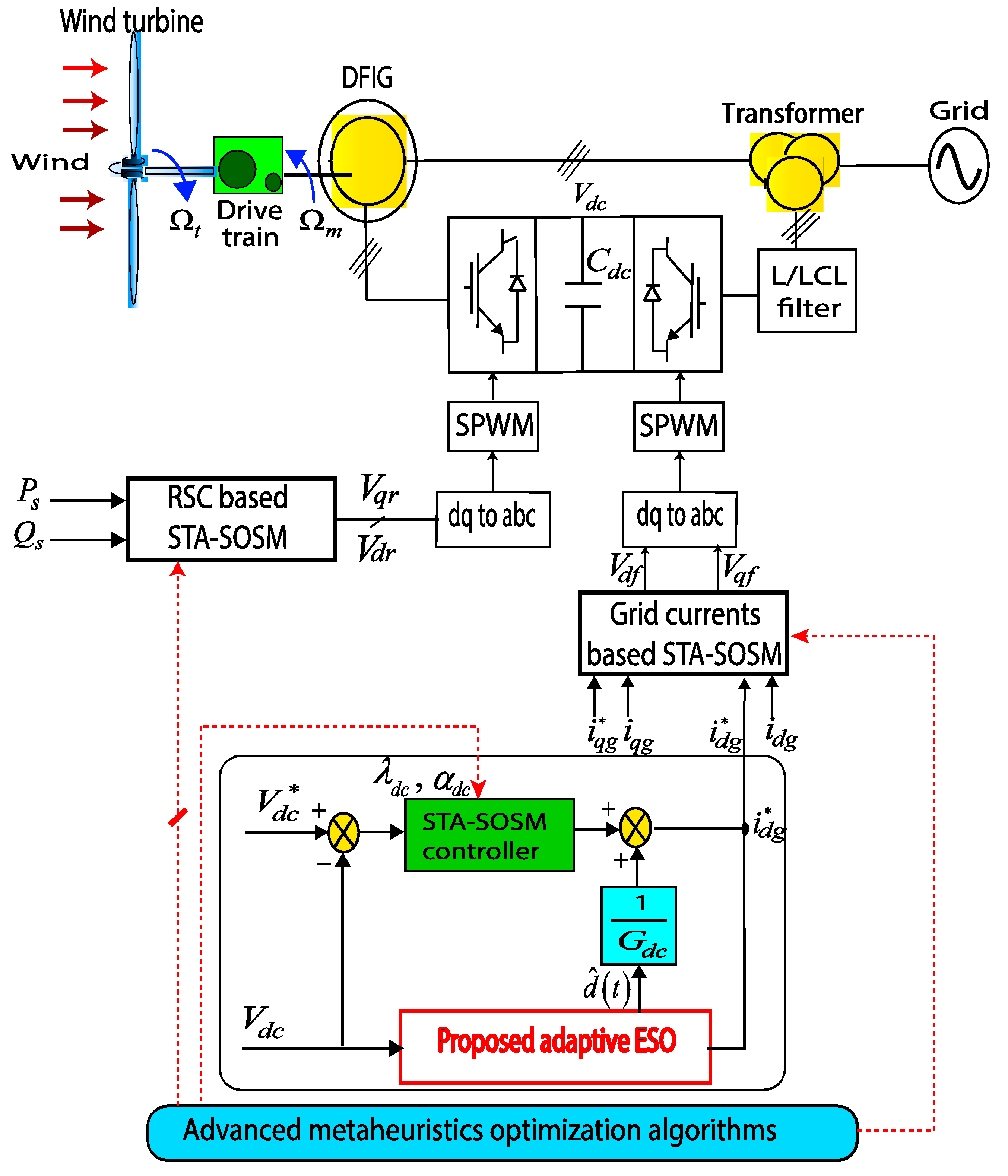
2. Modeling of the DFIG Based Wind Energy Converter

The GSC component is joined to the electrical net via an L or LCL filter. However, for a better harmonics reduction of the grid currents, architecture with an LCL filter is adopted [3,24]. The mathematical modeling of the GSC system is defined in the d-q synchronous reference frame as given by Equation (1). In these dynamics, L T states the sum of the converter and grid side inductances. Indeed, at the fundamental frequency, the LCL filter can be considered as an L-one with an inductance equal to the sum of the LCL-filter inductors [3]:
{ L T d i d g d t = R T i d g + ω g L T i q g + V d g V d f L T d i q g d t = R T i q g ω g L T i d g + V q g V q f d V d c d t = 1 C d c ( 3 2 V d g V d c i g d i r d c )
where C d c is the capacitance of the DC-link circuit and i r d c is the current between the DFIG rotor and the DC-link component.

3. Design of Second-Order Sliding Mode Controller

The main aim of the GSC control is to keep the DC-link voltage constant [5,7]. To perform this goal, Figure 1 presents the proposed control scheme. In such a design setup, the direct grid current is controlled thanks to the STA-based SOSM controller to maintain the DC-link voltage constant. The quadrature grid current can be used to regulate the reactive power’s flow between the GSC and the grid.

3.1. Controller Design

The DC-link voltage dynamics (1) can be rearranged under the following form [7,25]:
d V d c d t = G d c i d g 1 C d c i r d c = G d c i d g + η d c
where η d c represents the uncertainties, parametric mismatch, and external disturbances of the DC-link dynamics, and it is considered to be a bounded parameter and G d c = 1 C d c 3 2 V d g V d c .
Let us specify the dynamics of the DC-link voltage error as [7,25]:
s V D C = V d c V d c
The time derivative of the sliding surface s V D C is given as follows:
d s V d c d t = G d c i d g + η d c d V d c d t = u d c + η d c
where udc is the new control input as follows:
u d c = G d c i d g d V d c d t
While using the concept of the super twisting algorithm, a SOSM control law is designed to regulate the DC-link voltage as follows [15,25]:
{ u d c = λ d c | s V d c | 0.5 sgn ( s V d c ) + y d c d y d c d t = α d c sgn ( s V d c )
where λ d c and α d c are parameters to be designed.
Finally, the reference direct grid current i d g * can be derived from Equations (5) and (6) as follows:
{ i d g = 1 G d c ( λ d c | s V d c | 0.5 sgn ( s V d c ) + y d c + d V d c d t ) d y d c d t = α d c sgn ( s V d c )

3.2. Operational Constraints

The selection of the control gains of the SOSM is a significant issue where the best gains should guarantee good dynamic performances, stability, and robustness of the DFIG. The tuning of the control parameter by the conventional trial-and-error strategy is a time-consuming approach. Moreover, other classical methods such as the use of Hurwitz stability criterion for the linearized model of the DC-link voltage dynamics can attain the stability of the control law, but without securing that, the captured gains are the best parameters [26]. To improve the chosen of the control coefficients of the SOSM controller, advanced optimization algorithms are employed to process the tuning problem. In this instance, the restrictions that are forced on the control parameters by the Lyapunov theory are considered as inequality constraints for the optimization problem. This results in an improvement in tracking execution and chattering reduction.
The Lyapunov stability theory of the DFIG dynamics generates nonlinear limitations on the decision variables of the given control problem. By using the control law of Equation (7) and taking into consideration the derivative of the sliding surface as stated in Equation (4), the dynamics of s V d c will be defined as:
{ d s V d c d t = λ d c | s V d c | 0.5 sgn ( s V d c ) + y d c + η d c d y d c d t = α d c sgn ( s V d c )
Let us consider that the perturbation term η d c of the DC-link voltage dynamics (2) is globally bounded and described as follows [27,28]:
| η d c | Ψ d c | s V d c | 0.5   ;   Ψ d c 0
To draw sufficient conditions on the robust stability of the studied DC-link voltage dynamics, let us define the following quadratic Lyapunov function:
V d c ( s V d c , y d c ) = ξ d c T L d c ξ d c
where ξ d c = [ ξ 1 ξ 2 ] T = [ | s V d c | 0.5 sgn ( s V d c ) y d c ] T and L d c is a symmetric positive definite matrix, which takes the following form:
L d c = 1 2 [ 4 α d c + λ d c 2 λ d c λ d c 2 ]
Then, the time derivative of the candidate Lyapunov function V d c ( s V d c , y d c ) along the trajectories of the system (6) is calculated as:
d V d c d t ( s V d c , y d c ) = 1 | ξ 1 | ξ d c T M T ξ d c + η d c | ξ 1 | N T ξ d c
where M = λ d c 2 [ 2 α d c + λ d c 2 λ d c λ d c   1 ] and N T = [ ( 2 α d c + λ d c 2 2 ) λ d c 2 ] .
Using the bounds on the perturbations of Equation (9), it can be demonstrated that:
d V d c d t ( s V d c , y d c ) = 1 | ξ 1 | ξ d c T Q d c ξ d c
where Q d c is a symmetric matrix expressed as:
Q d c = λ d c 2 [ 2 α d c + λ d c 2 ( 4 α d c λ d c + λ d c ) Ψ d c ( λ d c + Ψ d c ) ( λ d c + Ψ d c )   1 ]
when this matrix is positive definite Q d c = Q d c T > 0 , the stability condition of the dynamics (2) is satisfied in the sense of Lyapunov until V ˙ d c ( s V d c , y d c ) < 0 as given in [29].
To have Q d c as a positive definite matrix, the range values of λ d c and α d c should be adjusted as follows:
{ λ d c > 2 Ψ d c = λ d c min α d c > λ d c 5 λ d c Ψ d c + 4 Ψ d c 2 2 ( λ d c 2 Ψ d c ) = α d c min
To enhance the performance of the DFIG system’s control, the optimization theory is adopted to select and tune the effective parameters of the SOSM controllers for the DC-link voltage, stator active/reactive powers, and grid current loops. Hence, the tuning problem related with the STA-SOSM controllers is completely formulated as a constrained optimization problem. Several time-domain performance metrics, i.e., maximum overshoot, steady-state error, rise and/or settling times, as well as the established stability and robustness conditions of Equation (15), are included as inequality constraints for the optimization problem defined as follows:
{ minimize   J m ( x , t ) , m { I A E , I S E , I T A E , I T S E } x = [ λ Q s , α Q s , λ d c , α d c , λ i d g , α i d g ] T S + 6 subject   to   : g 1 ( x , t ) = δ P s δ P s max 0 g 2 ( x , t ) = δ Q s δ Q s max 0 g 3 ( x , t ) = δ d c δ d c max 0 g 4 ( x , t ) = δ i d g δ i d g max 0 g 5 ( x , t ) = δ i q g δ i q g max 0 λ n , min λ n λ n , max α n , min α n α n , max , n { Q s , V d c , i d g }
where J m : + 6 are the cost functions, g q : + 6 are the problem’s inequality constraints, and δ d c , δ i d g , δ i q g , δ P s and δ Q s are the overshoots of the DC-link voltage, grid current components, and stator power components, respectively. The terms δ d c max , δ i d g max , δ i q g max , δ P s max and δ Q s max indicate their maximum specified values. The terms λ Q s , α Q s represent the gains of the SOSM controller for the stator power loop, and λ i d g and α i d g are the gains of the controller for the grid current loop.
In the formalism of optimal control theory, the objective functions of (16) are usually described by common performance standards, such as Integral Absolute Error (IAE), Integral Square Error (ISE), Integral Time-Weighted Absolute Error (ITAE), and Integral Time-Weighted Square Error (ITSE) [3,17,24,25]. Therefore, the global objective function using the IAE index for all controlled dynamics is aggregated as follows:
J I A E ( x , t ) = [ w V d c   w i d g   w i q g   w Q s   w P s ] [ 0 T | e d c ( x , t ) | d t 0 T | e i d g ( x , t ) | d t 0 T | e i q g ( x , t ) | d t 0 T | e Q s ( x , t ) | d t 0 T | e P s ( x , t ) | d t ]
where T denotes the total simulation time, w r { Q s , P s , V d c , i d g , i q g } is the weighting coefficient satisfying the convex summation r w r = 1 , and e i ( . ) is the tracking error defined as e P s ( x , t ) = P s * P s ( x , t ) , e Q s ( x , t ) = Q s * Q s ( x , t ) , e d c ( x , t ) = V d c V d c ( x , t ) , e i d g ( x , t ) = i d g i d g ( x , t ) , and e i q g ( x , t ) = i q g i q g ( x , t ) .

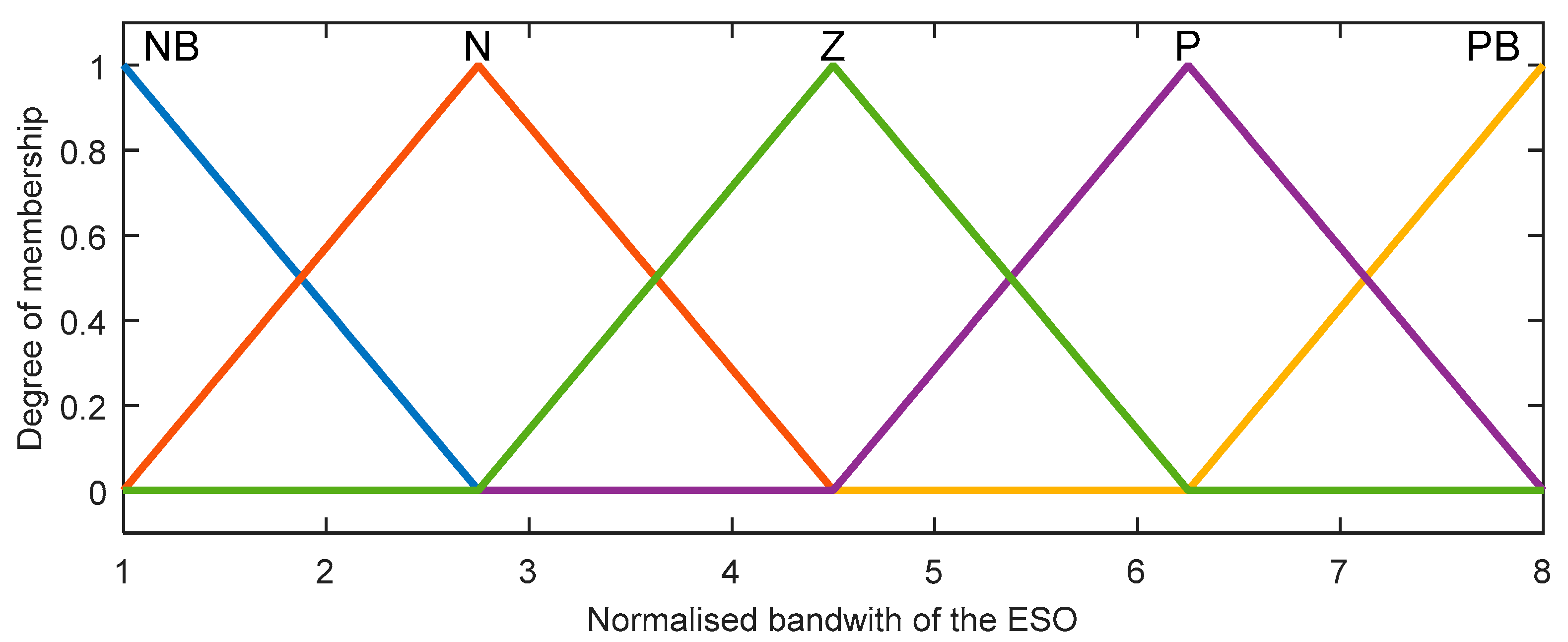
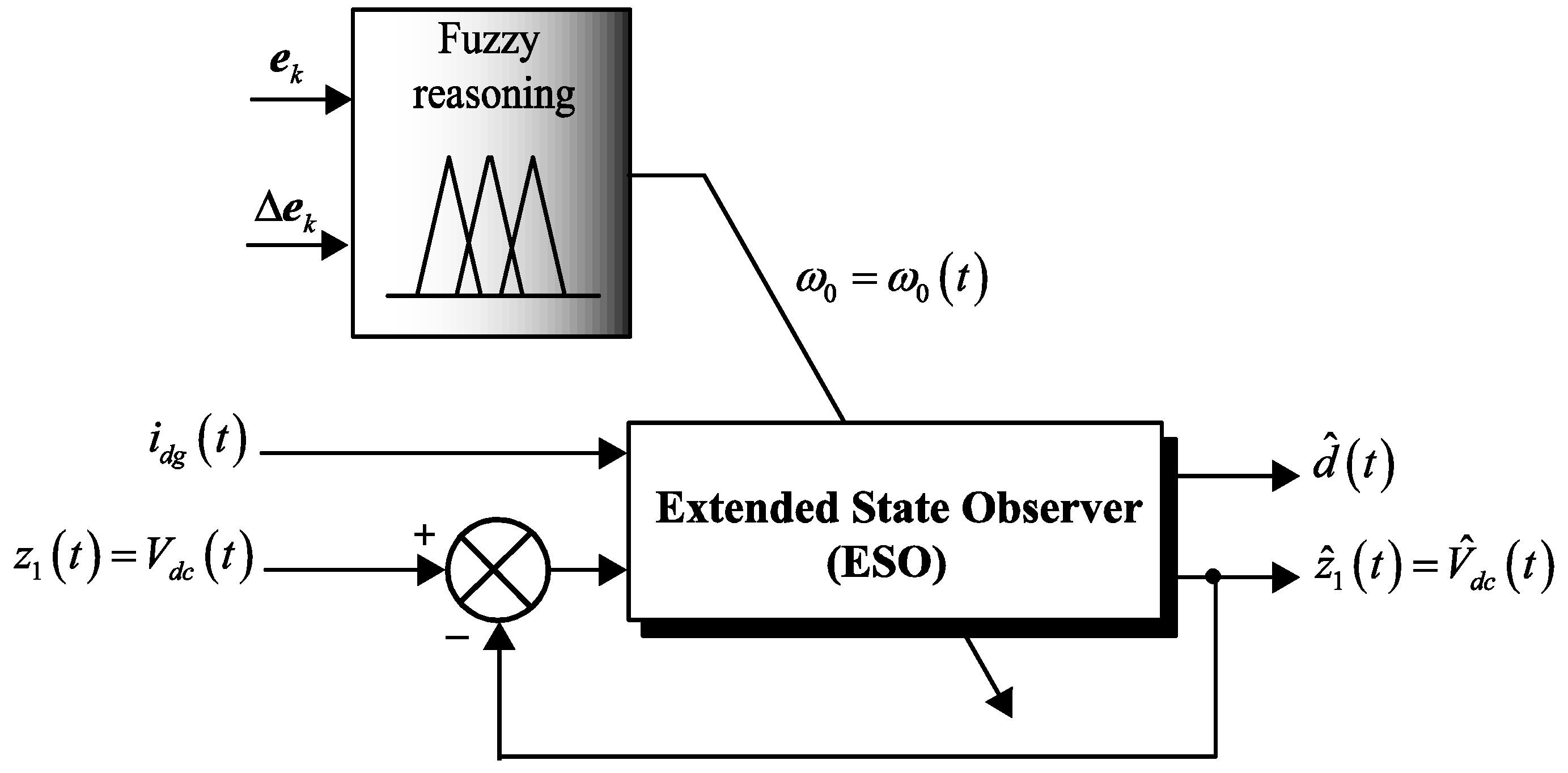
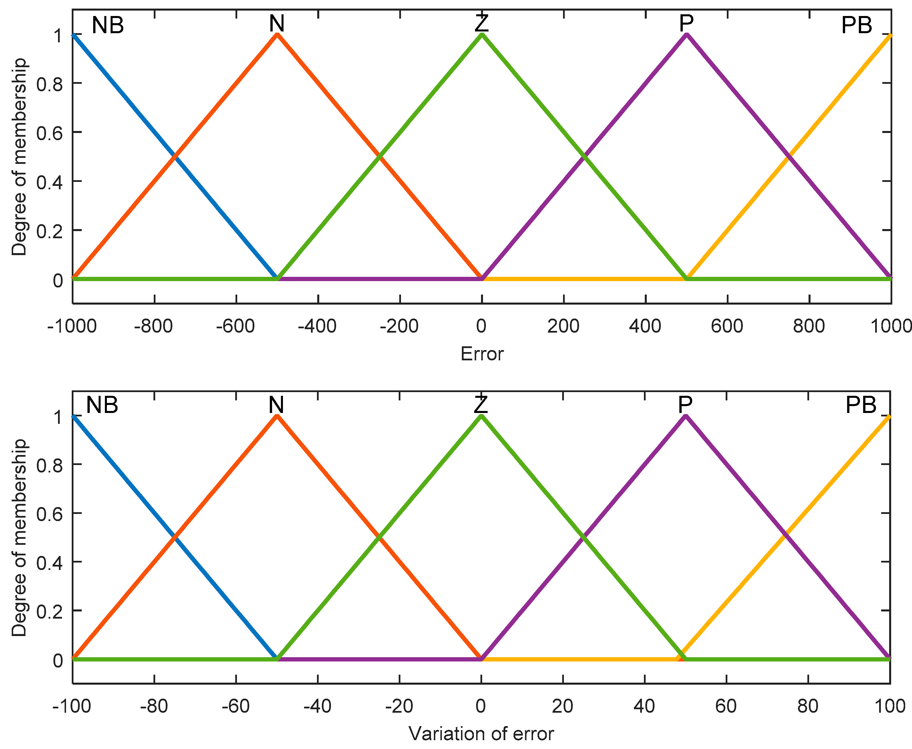
4. Adaptive Fuzzy ESO-Based Sliding Mode Controller

In this work, a fuzzy gain-scheduling mechanism is proposed to design an adaptive STA-SOSM controller for the DC-link voltage dynamics. An adaptive extended state observer (ESO) is designed to asymptotically estimate the disturbances and allow the STA-SOSM controller to reject them efficiently. Therefore, the adaptive fuzzy ESO is employed in the DC-link voltage loop to improve the control performance and robustness as shown in Figure 2.

4.1. Concept of Extended State Observers

The ESO treats the lumped disturbances of the system as a new system state which is conceived to estimate not only the external disturbances but also the plant dynamics [30,31].
However, for any arbitrary second-order system, an ESO can be written in the following state-space form [15,30]:
{ x ˙ 1 ( t ) = x 2 ( t ) x ˙ 2 ( t ) = f ( x 1 ( t ) , x 2 ( t ) , u ( t ) ) + b 0 u ( t ) + w ( t ) y ( t ) = x 1 ( t )
where x 1 ( t ) and x 2 ( t ) are the state variables of the cascade integral form, f ( x 1 ( t ) , x 2 ( t ) , u ( t ) ) defines the dynamics of the system which is a so-called internal disturbance, u ( t ) is the control variable, y ( t ) is the output variable, w ( t ) is an external disturbance, and b 0 is a given constant, and x ˙ ( t ) denotes the time derivative of the variable x ( t ) , i.e., x ˙ 1 ( t ) = d x 1 ( t ) d t , and so on.
For a given second-order system, a three-order ESO can be used with the disturbance as an additional state variable and defined as follows:
{ e ( t ) = z 1 ( t ) x 1 ( t ) z ˙ 1 ( t ) = z 2 ( t ) β 1 e ( t ) z ˙ 2 ( t ) = z 3 ( t ) + b 0 u ( t ) β 2 e ( t ) z ˙ 3 ( t ) = β 3 e ( t )
where β 1 , β 2 , and β 3 are the gains of the extended state observer.
In the state-space form (19), the ESO takes the system’s output y ( t ) = x 1 ( t ) and control variable u ( t ) as input and gives the state variables ( z 1 ( t ) , z 2 ( t ) , z 3 ( t ) ) which represent the estimations of system state variables ( x 1 ( t ) , x 2 ( t ) ) T 2 and total disturbances w ( t ) , respectively, i.e., z 1 ( t ) = x ^ 1 ( t ) , z 2 ( t ) = x ^ 2 ( t ) , and z 3 ( t ) = w ^ ( t ) . By properly selecting the feedback coefficients β 1 , β 2 , and β 3 , the estimation error e ( t ) converges asymptotically to a small value. Besides, from Equation (19), it is clear that the ESO does not depend on the system parameters and thus provides strong robustness for observer dynamics [30,31].

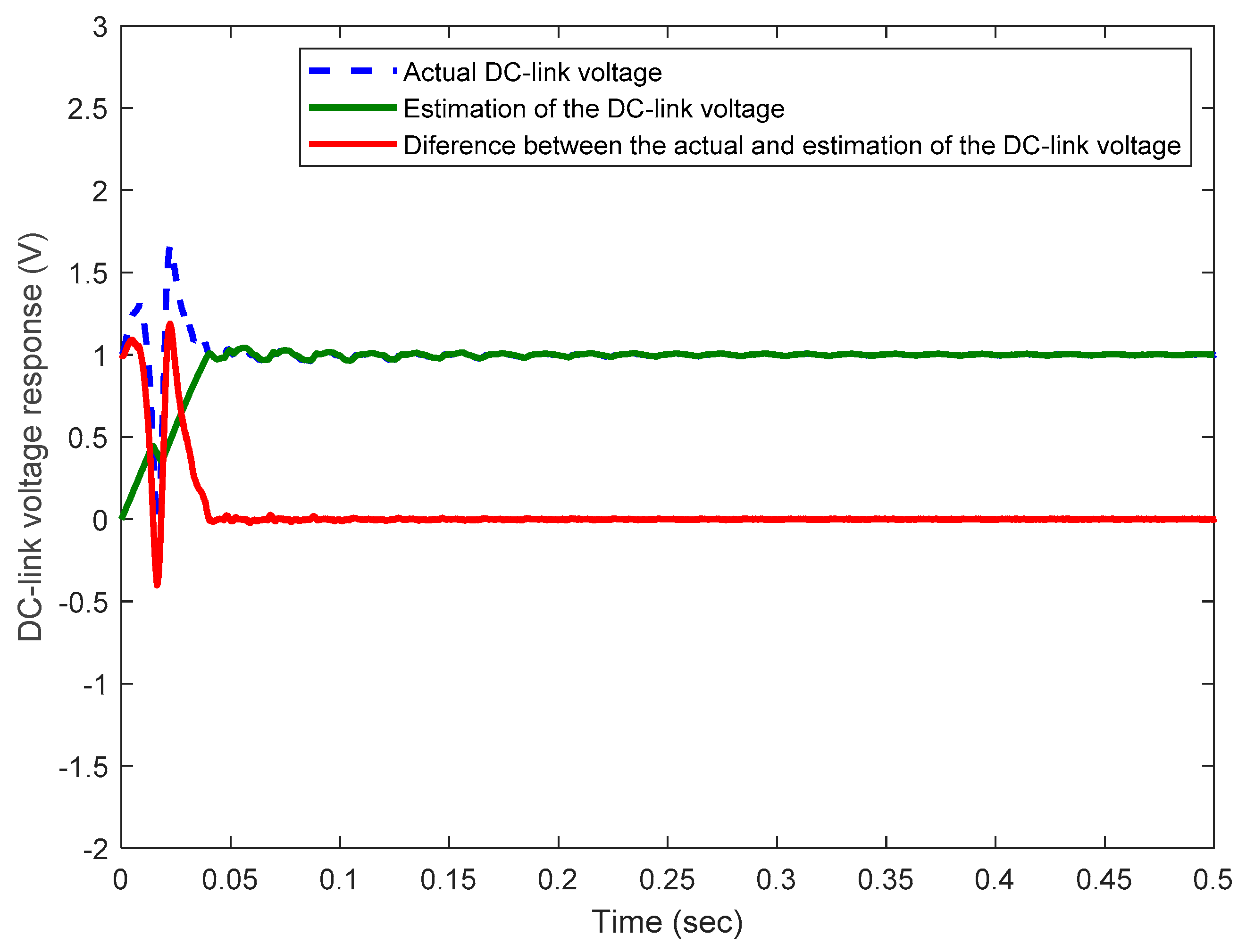
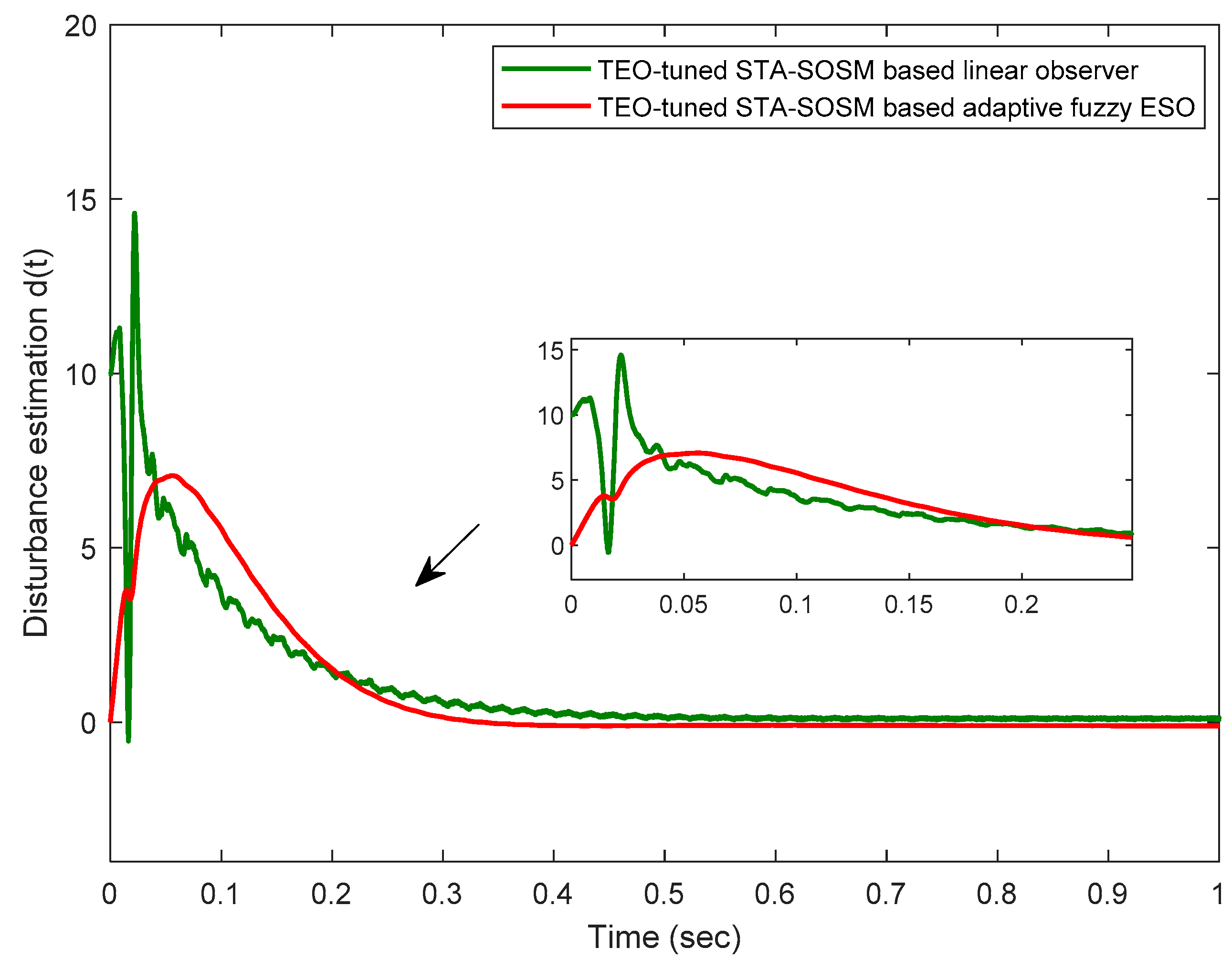
4.2. Extended State Observer for the DC-Link Voltage Loop

To design an extended state observer (19) for the DC-link voltage loop, the first state variable of such an observer is chosen as z 1 ( t ) = V d c ( t ) . Therefore, the dynamics of the DC-link voltage (2) can be reformulated as:
z ˙ 1 ( t ) = d V d c ( t ) d t = G d c u d c 0 ( t ) d ( t )
where u d c 0 ( t ) = i d g ( t ) , t 0 and d ( t ) = η d c ( t ) .
The ESO treats the external disturbance as an extended state. Therefore, a second-order ESO is used for the outer DC-link voltage loop, which is adopted as follows:
{ e 1 ( t ) = z 1 ( t ) z ^ 1 ( t ) z ^ ˙ 1 ( t ) = G d c u d c 0 ( t ) d ^ ( t ) + β 1 e 1 ( t ) d ^ ˙ ( t ) = β 2 e 1 ( t )
where   z ^ 1 ( t ) is an estimate of the output, z 1 ( t ) d ^ ( t ) is an estimate of the total disturbance d ( t ) = η d c ( t ) , and β 1 and β 2 are the ESO gains chosen as follows [13,30]:
[ β 1 ,   β 2 ] = [ 2 ω 0    ω 0 2 ] + 2
In Equation (22), the real ω 0 > 0 denotes the observer’s bandwidth that becomes the only tuning parameter of the extended state observer (21). Based on the above studies and the designed sliding-control law given in Equation (7), the proposed ESO-based control of the DC-link voltage loop is achieved by:
{ i d g = 1 G d c ( ( λ d c | s V d c | 0.5 sgn ( s V d c ) + y d c + d V d c d t ) + d ^ ( t ) ) d y d c d x = α d c sgn ( s V d c )
The choice of the adequate bandwidth of a given ESO is a difficult task action [32,33]. The appropriate selection can improve the closed-loop system’s performance, while the poor selection could degrade the time-domain performances and robustness of the controlled system. In general, the larger the ESO bandwidth, the more accurate the estimation of states will be achieved. On the other hand, the increase of such a bandwidth may lead to vulnerability against noise and loss of robustness. The design of an observer is always a trade-off between the estimation dynamics performance and the noise vulnerability [13,15]. Typically, the bandwidth of the ESO is selected to be 5 to 15 times the DC-link voltage controller’s bandwidth. However, this last is limited from 1/1000 to 1/100 of the switching frequency as discussed in [34]. In this research work, the idea to design a fuzzy gains-scheduling-based observer is proposed to overcome such a complex tuning problem. Such an adaptive fuzzy supervisor is proposed to avoid the aforementioned drawbacks and achieve high convergence performance and robustness of the designed ESO under operational disturbances and high-frequency noises. Figure 2 shows such a proposed adaptive-fuzzy extended state observer for the studied wind energy converter.
The approach taken here is to exploit the Mamdani type of fuzzy rules and reasoning to generate the appropriate values of the ESO’s bandwidth ω 0 + of Equation (21). Let us consider as inputs of the proposed fuzzy gains scheduler the linguistic variables e ( k T s ) = e k as the error between the actual and the estimated output, i.e., the sampled signals V d c and V ^ d c , respectively, and Δ e ( k T s ) = Δ e k as the change of error, where T s denotes the sampling period for the fuzzy supervisor. The designed fuzzy inference supervision mechanism produces the tuned bandwidth of the ESO denoted as ϖ 0 .
For this proposed fuzzy-based tuning mechanism, a Mamdani model is applied as a type of inference mechanism. The decision-making output can be acquired using a Max-Min fuzzy inference where the crisp output is computed by the center of gravity defuzzification approach. As shown in Figure 3, all used membership functions for fuzzy sets are triangular, uniformly distributed, and symmetrical on the universe of discourse.
A set of linguistic rules in the form of Equation (24) is utilized in the fuzzy reasoning inference to define the output ϖ 0 :
If   e k   is   A i   and   Δ e k   is   B i ,   then   ϖ 0   is   C i
where A i , B i , and C i are the fuzzy sets of the inputs/output linguistic variables e k , Δ e k , and ϖ 0 , respectively. The linguistic levels assigned to the fuzzy inputs and outputs are labeled as follows: negative big (NB), negative (N), zero (ZE), positive (P), and positive big (PB). A set of 25 rules are defined for this fuzzy inference as given in Table 1.
As proposed in [32,33], and since it is assumed that the ESO’s bandwidth parameter ω 0 varies in the prescribed range ω 0 min , ω 0 max , this effective parameter is calculated according to the following linear transformation [34]:
ω 0 = ( ω 0 max ω 0 min ) ϖ 0 + ω 0 min
where ω 0 max and ω 0 min are the maximum and minimum limits of ω 0 , respectively.

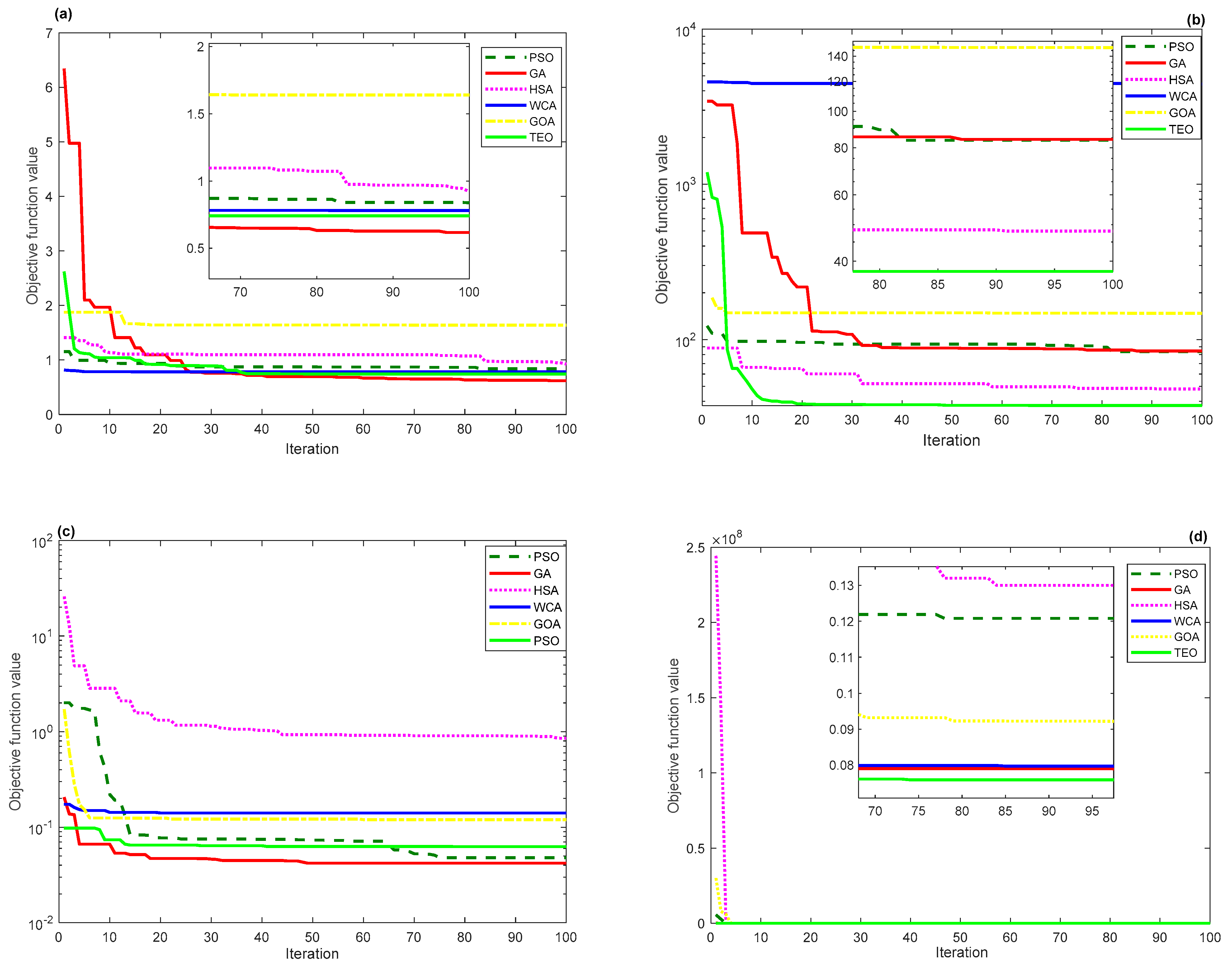
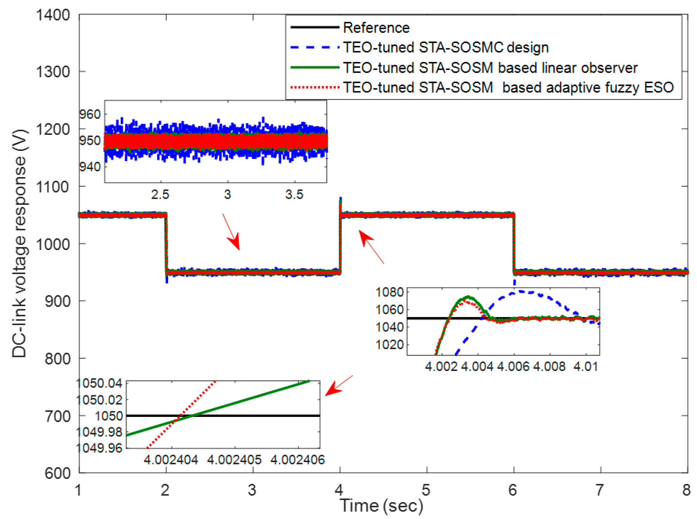
5. Results and Discussion

The proposed STA-SOSM controllers based on an adaptive fuzzy ESO for the DC-link voltage loop are built using MATLAB/Simulink environment. The introduced algorithms GA, PSO, HSA, WCA, GOA, and TEO were switched with the equal values for the mutual factors, i.e., population size N p o p = 50 and the maximum number of iterations N i t e r = 100 , and run on an Intel R CoreTMi5 CPU computer at 2.5 GHz and 8 GB of RAM. The parameters of the DFIG (1.5 MW) used in this work are given in our previous works [3]. The gains of the STA-SOSM controllers for the DC-link voltage and other control loops are tuned thanks to the proposed advanced optimization algorithms for the problems (16) and (17).
Figure 4 shows the convergence curves of the cost functions for the considered time-domain performance indices. Moreover, the TEO algorithm for the ISE and ITSE criteria outperforms the other reported methods in terms of fast and non-premature convergence. Figure 4a,c show that the TEO for the IAE and ITAE indicators display the better convergence as a second- and third-order, respectively, after the GA one.
Since the TEO metaheuristic outperformed all the other reported ones, the effective gains λ d c and α d c of the STA-SOSM controller, retained for the rest of the control strategy, are selected as the best results obtained by the TEO algorithm of the optimization problem (16) and (17). Table 2 summarizes such decision variables for each time-domain performance criterion.
Besides, the bandwidth of the ESO is selected to be between 1/200 and 15/100 of the switching frequency for the GSC circuit. The fuzzy gains-scheduling mechanism is employed to adaptively tune the bandwidth of the ESO within the predefined limits. The obtained fuzzy surface for the bandwidth gain is presented in Figure 5. On the other hand, Figure 6 shows the histories of the scheduled gain of the proposed adaptive fuzzy ESO. Figure 7 presents the performance of the DC-link voltage when different input steps are set. It can be noted that the chattering phenomenon is reduced using the proposed TEO and fuzzy-based method in comparison with the STA-SOSM and PI controllers-based ones.
Moreover, the STA-SOSM controller based on different types of observers leads to lower DC-link voltage overshoot and faster response compared with the STA-SOSM and classical PI controllers-based cases as summarized in Table 3. Indeed, the proposed design and tuning method is compared to the STA-SOSM controller associated with a linear observer as well as without observers to show its superiority and effectiveness. Also, Figure 8 presents the time-domain performance of the DC-link voltage controller under severe voltage dips conditions. Since a 30% voltage drop is considered, the proposed adaptive fuzzy observer and TEO-based tuning method are successfully able to mitigate the voltage dip.
Based on these demonstrative results, one can notice that the lower amplitude of the fluctuations exists near the starting of the voltage dips in comparison with the STA-SOSM controller only. However, the proposed robust and intelligent STA-SOSM controllers based on linear and ESO observers present approximately the same performance in the case of DC-link voltage dips. Further comparison in terms of Total Harmonic Distortion (THD) variation is made in Table 4.
The currents THD of stator and rotor for the adaptive fuzzy ESO-based SOSM controllers are about 0.26% and 0.28%, respectively. These values are better than the other reported design methods, such as TEO-tuned PI controller, TEO-tuned STA-SOSM controller, and STA-SOSM controller-based linear observer. In addition, these values agree with the limits of the IEEE519-1992 standard which stipulate that the value of the THD does not exceed 5%. The DC-link voltage states and their according estimations and observation errors are shown in Figure 9 and Figure 10 for linear and adaptive fuzzy ESO observers, respectively. The observation errors are obtained as the difference between the actual value of the DC-link voltage and the value estimated by the observers, i.e., e = V d c V ^ d c .
The estimation dynamics using the different proposed observers are perfectly ensured. However, the adaptive fuzzy ESO presents a faster convergence and reconstruction of the system’s state than in the linear observer-based case, i.e., an observation error reached null value after 0.05 s with ESO compared to 0.3 sec with the linear observer. Moreover, Figure 11 gives the total disturbance estimations for the linear and adaptive fuzzy ESO observers, respectively. Such a convergence rate comparison and total disturbance estimation of observers indicate the effectiveness and superiority of the proposed adaptive fuzzy extended state observer for the DC-link voltage regulation.
In a wind conversion system, the external disturbances’ upper bound is unknown and is hard to be estimated in an actual doubly-fed induction generator. Therefore, the fuzzy gain-scheduled ESO is proposed in this work to compel observer parameters to vary according to the disturbances’ upper bound in real-time. The uncertainty upper limit is required when developing the DC-link voltage second-order sliding mode controller, yet the upper limits are unknown in practical wind conversion systems and are difficult to be estimated. Overestimation of these upper bounds may lead to a conservative choice of controller parameters which will produce more control effectiveness, aggravate control chattering, and shorten the service cycle of wind turbines.

6. Conclusions

This paper discussed the robust design and intelligent tuning of super twisting-based second order sliding mode (STA-SOSM) controllers for the DC-link voltage loop of a DFIG-based wind energy conversion system. An adaptive fuzzy extended state observer (ESO) is firstly proposed to estimate the external disturbance of the controlled system. Such a proposed fuzzy gains-scheduling mechanism is performed to adaptively tune the bandwidth of the ESO during the occurrence of disturbances. Such a hybrid control law based on a TEO-tuned SOSM controller and adaptive extended state observer showed high superiority and robustness under grid disturbances and model uncertainties as well as in terms of closed-loop time-domain performance and chattering issue reduction. The simulation results as well as the conducted comparisons proved that the proposed algorithm gives the best THD values for the stator and rotor current with 0.26% and 0.28%, respectively. Moreover, the time-domain performance indices were better than those with the reported methods, such as TEO-tuned PI controller, TEO-tuned STA-SOSM controller, and STA-SOSM controller-based linear observer, which had the minimal value of overshoot with 1.81% for the DC-link voltage response. This clearly highlights the effectiveness of the proposed intelligent and adaptive fuzzy-based control approach for the DC-link voltage dynamics.
The current research work is restricted by supposing that the wind speed is fixed. Moreover, the proposed approach investigated a low voltage dip condition. Stability enhancement of the DFIG system under the previous concerns will be deeply investigated in future work. This will be implemented through interactions among DFIGs with various control methods, such as adaptive gain SOSM controllers and sensor-less control methods. Indeed, these methods deserve attention because they solve the difficulty of estimating the disturbance upper bounds for WECSs.

Author Contributions

Conceptualization, M.M.A. and S.B.; methodology, M.M.A., S.B. and M.N.I.; software, M.M.A.; validation, H.R. and S.B.; formal analysis, M.N.I. and S.B.; investigation, H.R. and S.B.; resources, M.M.A., S.B. and H.R.; data curation, M.M.A.; writing—original draft preparation, M.M.A.; writing—review and editing, H.R. and S.B.; visualization, H.R. and M.N.I.; supervision, H.R. and S.B.; project administration, M.N.I. and S.B.; funding acquisition, M.N.I. and H.R. All authors have read and agreed to the published version of the manuscript.

Funding

This research received no external funding.

Institutional Review Board Statement

Not applicable.

Informed Consent Statement

Not applicable.

Data Availability Statement

No new data were created or analyzed in this study.

Conflicts of Interest

The authors declare no conflict of interest.

References

  1. Khaligh, A.; Onar, O.C. Energy Harvesting Solar, Wind, and Ocean Energy Conversion Systems, 1st ed.; CRC Press, Taylor & Francis Group: New York, NY, USA, 2009. [Google Scholar]
  2. Ahsan, H.; Mufti, M.D. Systematic development and application of a fuzzy logic equipped generic energy storage system for dynamic stability reinforcement. Int. J. Energy Res. 2020, 44, 8974–8987. [Google Scholar] [CrossRef]
  3. Alhato, M.M.; Bouallègue, S. Direct power control optimization for doubly fed induction generator based wind turbine systems. Math. Comput. Appl. 2019, 24, 77. [Google Scholar] [CrossRef] [Green Version]
  4. Naika, K.A.; Gupta, C.P.; Fernandez, E. Design and implementation of interval type-2 fuzzy logic-PI based adaptive controller for DFIG based wind energy system. Int. J. Electr. Power Energy Syst. 2020, 115, 105468. [Google Scholar] [CrossRef]
  5. Pena, R.; Clare, J.; Asher, G. Doubly fed induction generator using back-to-back PWM converters and its application to variable-speed wind-energy generation. IEE Proc. Electr. Power Appl. 1996, 143, 231. [Google Scholar] [CrossRef] [Green Version]
  6. Gagra, S.K.; Mishra, S.; Sing, M. Performance analysis of grid integrated doubly fed induction generator for a small hydro-power plant. Int. J. Renew. Energy Res. 2018, 8, 2310–2323. [Google Scholar]
  7. Djilali, L.; Sanchez, E.N.; Belkheiri, M. Real-time implementation of sliding-mode field-oriented control for a DFIG-based wind turbine. Int. Trans. Electr. Energy Syst. 2018, 28, e2539. [Google Scholar] [CrossRef]
  8. Merabet, A.; Eshaft, H.; Tanvir, A.A. Power-current controller based sliding mode control for DFIG-wind energy conversion system. IET Renew. Power Gener. 2018, 12, 1155–1163. [Google Scholar] [CrossRef]
  9. Barambones, O.; Cortajarena, J.A.; Alkorta, P.; De Durana, J.M.G. A Real-Time Sliding Mode Control for a Wind Energy System Based on a Doubly Fed Induction Generator. Energies 2014, 7, 6412–6433. [Google Scholar] [CrossRef]
  10. Xiong, L.; Li, P.; Li, H.; Wang, J. Sliding Mode Control of DFIG Wind Turbines with a Fast Exponential Reaching Law. Energies 2017, 10, 1788. [Google Scholar] [CrossRef] [Green Version]
  11. Kim, S.-C.; Nguyen, T.H.; Lee, D.-C.; Lee, K.-B.; Kim, J.-M. Fault Tolerant Control of DC-Link Voltage Sensor for Three-Phase AC/DC/AC PWM Converters. J. Power Electron. 2014, 14, 695–703. [Google Scholar] [CrossRef] [Green Version]
  12. Merai, M.; Naouar, M.W.; Slama-Belkhodja, I.; Monmasson, E. An improved dc-link voltage control for a three-phase PWM rectifier using an adaptive PI controller combined with load current estimation. In Proceedings of the 2017 19th European Conference on Power Electronics and Applications (EPE’17 ECCE Europe), Warsaw, Poland, 11–14 September 2017; pp. 1–10. [Google Scholar]
  13. Lu, J.; Golestan, S.; Savaghebi, M.; Vasquez, J.C.; Guerrero, J.M.; Marzabal, A. An Enhanced State Observer for DC-Link Voltage Control of Three-Phase AC/DC Converters. IEEE Trans. Power Electron. 2018, 33, 936–942. [Google Scholar] [CrossRef] [Green Version]
  14. Song, G.; Cao, B.; Chang, L.; Shao, R.; Xu, S. A Novel DC-Link Voltage Control for Small-Scale Grid-Connected Wind Energy Conversion System. In Proceedings of the 2019 IEEE Applied Power Electronics Conference and Exposition (APEC), Anaheim, CA, USA, 17–21 March 2019; pp. 2461–2466. [Google Scholar]
  15. Liu, J.; Vazquez, S.; Wu, L.; Marquez, A.; Gao, H.; Franquelo, L.G. Extended State Observer-Based Sliding-Mode Control for Three-Phase Power Converters. IEEE Trans. Ind. Electron. 2016, 64, 22–31. [Google Scholar] [CrossRef] [Green Version]
  16. Blasko, V.; Kaura, V. A new mathematical model and control of a three-phase AC-DC voltage source converter. IEEE Trans. Power Electron. 1997, 12, 116–123. [Google Scholar] [CrossRef]
  17. Alhato, M.M.; Bouallègue, S. Thermal exchange optimization based control of a doubly fed induction generator in wind en-ergy conversion system. Indones. J. Electr. Eng. Comput. Sci. 2020, 20, 1–8. [Google Scholar]
  18. Kaveh, A.; Dadras, A. A novel meta-heuristic optimization algorithm: Thermal exchange optimization. Adv. Eng. Softw. 2017, 110, 69–84. [Google Scholar] [CrossRef]
  19. Eskandar, H.; Sadollah, A.; Bahreininejad, A.; Hamdi, M. Water cycle algorithm—A novel metaheuristic optimization method for solving constrained engineering optimization problems. Comput. Struct. 2012, 110, 151–166. [Google Scholar] [CrossRef]
  20. Mohamed, M.A.; Diab, A.A.Z.; Rezk, H. Partial shading mitigation of PV systems via different meta-heuristic techniques. Renew. Energy 2019, 130, 1159–1175. [Google Scholar] [CrossRef]
  21. Holland, J.H. Genetic algorithms. Sci. Am. 1992, 276, 66–72. [Google Scholar] [CrossRef]
  22. Saremi, S.; Mirjalili, S.; Lewis, A. Grasshopper Optimisation Algorithm: Theory and application. Adv. Eng. Softw. 2017, 105, 30–47. [Google Scholar] [CrossRef] [Green Version]
  23. Geem, Z.W.; Kim, J.H.; Loganathan, G. A New Heuristic Optimization Algorithm: Harmony Search. Simulation 2001, 76, 60–68. [Google Scholar] [CrossRef]
  24. Alhato, M.M.; Bouallègue, S. Whale optimization algorithm for active damping of LCL-filter-based grid-connected converters. Int. J. Renew. Energy Res. 2019, 9, 986–996. [Google Scholar]
  25. Alhato, M.M.; Bouallègue, S.; Rezk, H. Modeling and Performance Improvement of Direct Power Control of Doubly-Fed Induction Generator Based Wind Turbine through Second-Order Sliding Mode Control Approach. Mathematics 2020, 8, 2012. [Google Scholar] [CrossRef]
  26. Matas, J.; Castilla, M.; Guerrero, J.M.; De Vicuna, L.G.; Miret, J. Feedback Linearization Of Direct-Drive Synchronous Wind-Turbines Via a Sliding Mode Approach. IEEE Trans. Power Electron. 2008, 23, 1093–1103. [Google Scholar] [CrossRef]
  27. Shtessel, Y.B.; Moreno, J.A.; Plestan, F.; Fridman, L.M.; Poznyak, A.S. Super-twisting adaptive sliding mode control: A Lyapunov design. In Proceedings of the 49th IEEE Conference on Decision and Control, Atlanta, GA, USA, 15–17 December 2010; pp. 5109–5113. [Google Scholar]
  28. Liu, X.; Han, Y.; Wang, C. Second-order sliding mode control for power optimization of DFIG-based variable speed wind turbine. IET Renew. Power Gener. 2017, 11, 408–418. [Google Scholar] [CrossRef]
  29. Levant, A. Sliding order and sliding accuracy in sliding mode control. Int. J. Control 1993, 58, 1247–1263. [Google Scholar] [CrossRef]
  30. Zheng, Q.; Gao, L.Q.; Gao, L. On stability analysis of active disturbance rejection control for nonlinear time-varying plants with unknown dynamics. In Proceedings of the 46th IEEE Conference on Decision and Control, New Orleans, LA, USA, 12–14 December 2007; pp. 3501–3506. [Google Scholar]
  31. Han, J. From PID to Active Disturbance Rejection Control. IEEE Trans. Ind. Electron. 2009, 56, 900–906. [Google Scholar] [CrossRef]
  32. Zhao, Z.-Y.; Tomizuka, M.; Isaka, S. Fuzzy gain scheduling of PID controllers. IEEE Trans. Syst. Man Cybern. 1993, 23, 1392–1398. [Google Scholar] [CrossRef] [Green Version]
  33. Blanchett, T.; Kember, G.; Dubay, R. PID gain scheduling using fuzzy logic. ISA Trans. 2000, 39, 317–325. [Google Scholar] [CrossRef]
  34. Zhou, D.; Blaabjerg, F. Bandwidth oriented proportional-integral controller design for back-to-back power converters in DFIG wind turbine system. IET Renew. Power Gener. 2017, 11, 941–951. [Google Scholar] [CrossRef] [Green Version]
Figure 1. General block diagram for the proposed control scheme method.
Mathematics 09 00963 g001
Figure 2. Adaptive fuzzy ESO-based SOSM controller for the DC-link voltage.
Mathematics 09 00963 g002
Figure 3. Membership functions of the proposed fuzzy gains-scheduling mechanism.
Mathematics 09 00963 g003aMathematics 09 00963 g003b
Figure 4. Convergence curves comparison: (a) IAE; (b) ISE; (c) ITAE; and (d) ITSE criterion.
Mathematics 09 00963 g004
Figure 5. Fuzzy surface of the observer’s bandwidth parameter ϖ 0 .
Mathematics 09 00963 g005
Figure 6. Time histories of the observer’s bandwidth control ϖ 0 .
Mathematics 09 00963 g006
Figure 7. Time-domain performances’ comparison of the DC-link voltage.
Mathematics 09 00963 g007
Figure 8. Time-domain responses of the controlled DC-link voltage under drop conditions.
Mathematics 09 00963 g008
Figure 9. Convergence’s dynamics of the linear observer for the DC-link voltage.
Mathematics 09 00963 g009
Figure 10. Dynamic performance of the adaptive fuzzy ESO for the DC-link voltage.
Mathematics 09 00963 g010
Figure 11. Total disturbance estimations’ comparison of the reported observers.
Mathematics 09 00963 g011
Table 1. Fuzzy rules for the ϖ 0 parameter’s tuning.
ϖ 0 Δ e k
NBNZEPPB
e k NBNBNBNBNZE
NNBNNNZE
ZENBNZEPPB
PZEPPPPB
PBZEPPBPBPB
Table 2. TEO-based results for the STA-SOSM controllers’ gains tuning.
Performance CriteriaSTA-SOSM Controllers’ Gains
λ d c α d c
IAE26.1014.50
ISE17.4093.60
ITAE1.9090.50
ITSE12.3053.90
Table 3. Time-domain performances’ comparison for the controlled DC-link voltage dynamics.
Control StrategiesUnit Step Change Response
t r ( s ) t s ( s ) δ E s s
TEO-tuned PI controller0.0054.0192.540.253
TEO-tuned STA-SOSM controller0.0044.0122.950.246
STA-SOSM controller-based linear observer0.0024.0062.380.115
STA-SOSM controller-based adaptive fuzzy ESO0.0024.005 1.810.086
Table 4. Comparison of stator and rotor currents’ THD.
Control StrategiesTHD (%)
Stator CurrentRotor Current
TEO-tuned PI controller 0.770.85
TEO-tuned STA-SOSM controller0.280.32
STA-SOSM controller-based linear observer0.270.30
STA-SOSM controller-based adaptive fuzzy ESO0.260.28
Publisher’s Note: MDPI stays neutral with regard to jurisdictional claims in published maps and institutional affiliations.

