Article

Analytical Modelling of LACFCST Stub Columns Subjected to Axial Compression

1
School of Civil Engineering, Central South University, Changsha 410075, China
2
Engineering Technology Research Center for Prefabricated Construction Industrialization of Hunan Province, Changsha 410075, China
*
Authors to whom correspondence should be addressed.
Mathematics 2021, 9(9), 948; https://doi.org/10.3390/math9090948
Submission received: 20 March 2021 / Revised: 12 April 2021 / Accepted: 14 April 2021 / Published: 23 April 2021
(This article belongs to the Section Mathematical Physics)

Abstract

:
This paper presents a numerical investigation of lightweight aggregate concrete-filled circular steel tubular (LACFCST) stub columns under axial compression. A finite 3D solid element model of the LACFCST stub column was established by adopting a plastic-damage constitutive model of lightweight aggregate concrete (LAC). The finite element model (FEM) analysis results revealed that the confinement effect of the steel tube on the infilled LAC was weaker than that on the infilled conventional concrete. A parametric study making use of 95 full-scale FEMs was conducted to investigate the influences of various design parameters of LACFCST stub columns on their ultimate axial bearing capacity and the composite actions. Moreover, a numerical model of the axial and transverse stress of steel tubes at the ultimate state of LACFCST columns was proposed using the regression method. Based on the equilibrium conditions and the proposed model, a practical design formula making use of an enhancement factor was derived to estimate the ultimate bearing capacity of LACFCST stub columns by using the superposition method. The validity of the proposed formula was verified against the experimental data of 49 LACFCST stub column specimens under the axial loading available in the literature. Meanwhile, the accuracy and conciseness of the proposed formula were evaluated by comparison with the formulas suggested by the existing design codes.

1. Introduction

In the past several decades, steel–concrete composite structures have been increasingly used in long-span bridges and super high-rise buildings around the world with the progress of social demands. A tendency to ascend the scale of engineering structures caused the self-weight of structural members to become a crucial factor in design, affecting the construction difficulty and the cost. T. G. Ghazijahani et al. [1] modified composite columns using timber as the infilled material, aiming to reduce the self-weight. With the merits of being lightweight and high-strength with good seismic performance, LAC is considered one of the effective ways to reduce structural dead load among the engineering community. Compared with conventional concrete which uses natural aggregates, the unit mass of LAC with a similar strength level is 20–30% lighter, yet its mechanical performance, such as the ductility [2] and bond strength [3], may be even better in some cases. These superior behaviors of LAC give it broad application prospects, especially in the aforementioned large-scale structures. On the other hand, LAC is more prone to aggregate fracture, which leads to lower elastic modulus and increased brittleness compared with conventional concrete. These defects have been experimentally verified by existing studies [4], and the importance of providing rational confinement in the usage of LAC has been noticed. Currently, concrete-filled steel tube (CFST) columns are one of the most favored and versatile composite members in structural engineering and are extensively utilized as bridge piers and building columns, and utilized in elevated structures. The composite action, namely the interaction between the steel tube and infilled concrete, enables the columns to fully exploit the advantages of constituent materials and circumvent their defects. Therefore, the CFST columns show an upgraded mechanical performance in their load-carrying capacity, ductility and energy dissipation capacity [5,6,7] compared to conventional structural columns, such as reinforced concrete and hollow steel columns. Since the outer steel tube can serve as a significant reinforcement of infilled concrete, infilling the LAC into the steel tube, forming a type of composite structural column, is thereby expected to have a satisfactory improvement of the mechanical performance of LAC.
The lightweight aggregate concrete-filled steel tubular columns have already gained some interest among the academic society. Ghannam et al. [8] conducted a series of tests of the square, rectangular and circular steel tubes filled with conventional concrete and LAC to investigate the failure modes of the composite columns. The test results revealed that both types of the composite columns lose their bearing capacity due to the overall buckling of the outer steel tubes; M. Abhilash et al. [9] presented an experimental investigation of CFST columns using semi-lightweight aggregate concrete as an infill, and investigated the effects of variations in the diameter, width, thickness and length-to-diameter ratio of the outer steel tube on the ultimate axial load-bearing capacity and axial shortening behaviors of both the circular and square columns. Based on the experimental investigations, the semi-lightweight aggregate concrete can serve as an alternative to the conventional concrete in CFST columns. The strength behaviors of semi-lightweight concrete were enhanced by the confinement of the steel tube. Thus, it provides comparable axial load-carrying capacity with a smaller self-weight. Salgar et al. [10] conducted an experimental and analytical study on the lightweight aggregate concrete-filled steel tubular columns with the cross-section types of circular, square and rectangular, subjected to the concentric load to failure. The ultimate strength obtained from the test was compared to the current specifications governing the design of CFST stub columns, such as Eurocode 4 [11] and American standards [12]. The results suggested that the load-carrying capacity of lightweight aggregate concrete-filled steel tubular columns were found to be comparable to conventional concrete-filled specimens, and the circular tubes can provide substantial post-yield strength and stiffness, while the square and rectangular cross-sections cannot. Zhang et al. [13] investigated the axial compressive performance of LACFCST stub columns with different replacement ratios of normal gravel aggregate, and the results revealed that the ultimate bearing capacities and the corresponding displacements of the stub columns increased with an increase in the normal gravel replacement ratio. Fu et al. [14,15,16,17] conducted experiments on LACFCST stub columns for the interface bond behaviors between the steel tube and infilled LAC, and a calculation method for ultimate bearing capacity was proposed. Gao and Li [18] performed an experimental study on the seismic behaviors of a lightweight aggregate concrete-filled rectangular steel tubular (LACFRST) frame. In their study, by testing four specimens subjected to a constant axial load and horizontal cyclic load, the LACFRST frame was verified to have excellent seismic behaviors compared to the specimens filled with standard weight concrete.
To sum up, the mechanical behaviors of lightweight aggregate concrete-filled steel tubular columns have been experimentally investigated in past research. However, there is still a lack of the theoretical basis and numerical analysis of the composite actions of LACFCST stub columns under an axial load. Due to the limitation of measuring technology, a detailed FEM analysis is the only method capable of investigating the interaction between the components of CFST columns during the loading process. Different from the existing studies about the CFST columns, which has a large number of advanced numerical analyses, a rare FEM analysis of LACFCST has been performed. Meanwhile, the difference between the confinement effectiveness of LACFCST and concrete-filled circular steel tubular (CFCST) stub columns also need to be clearly illustrated so that the current design formulas of CFCST columns can be rationally modified.
Therefore, the objective of the presented study is to investigate the composite action in LACFCST columns numerically and to propose a numerical model and design formula based on our past research of CFCST stub columns [19,20]. The main contents of this paper include the following: (1) a fine-meshed finite 3D solid element model of LACFCST stub columns was established by adopting an elastoplastic constitutive model of steel and a plastic-damage constitutive model of LAC. The non-linear finite element (FE) analysis was carried out, and the validity of the presented numerical analysis was verified against the collected experiment results of the ultimate bearing capacity and the whole loading-shortening curves; (2) based on the validated model, a parametric study was performed, and the different composite action between the LACFCST and CFCST stub columns was discussed. A composite action model of LACFCST stub columns was proposed; (3) based on the composite action model, a practical design formula utilizing an enhancement factor was proposed to predict the ultimate bearing capacity of the LACFCST stub columns. The proposed design formula was evaluated by comparison of the existing formulas in current design codes using available experimental data.

2. Finite Element Modelling of LACFCST Stub Columns

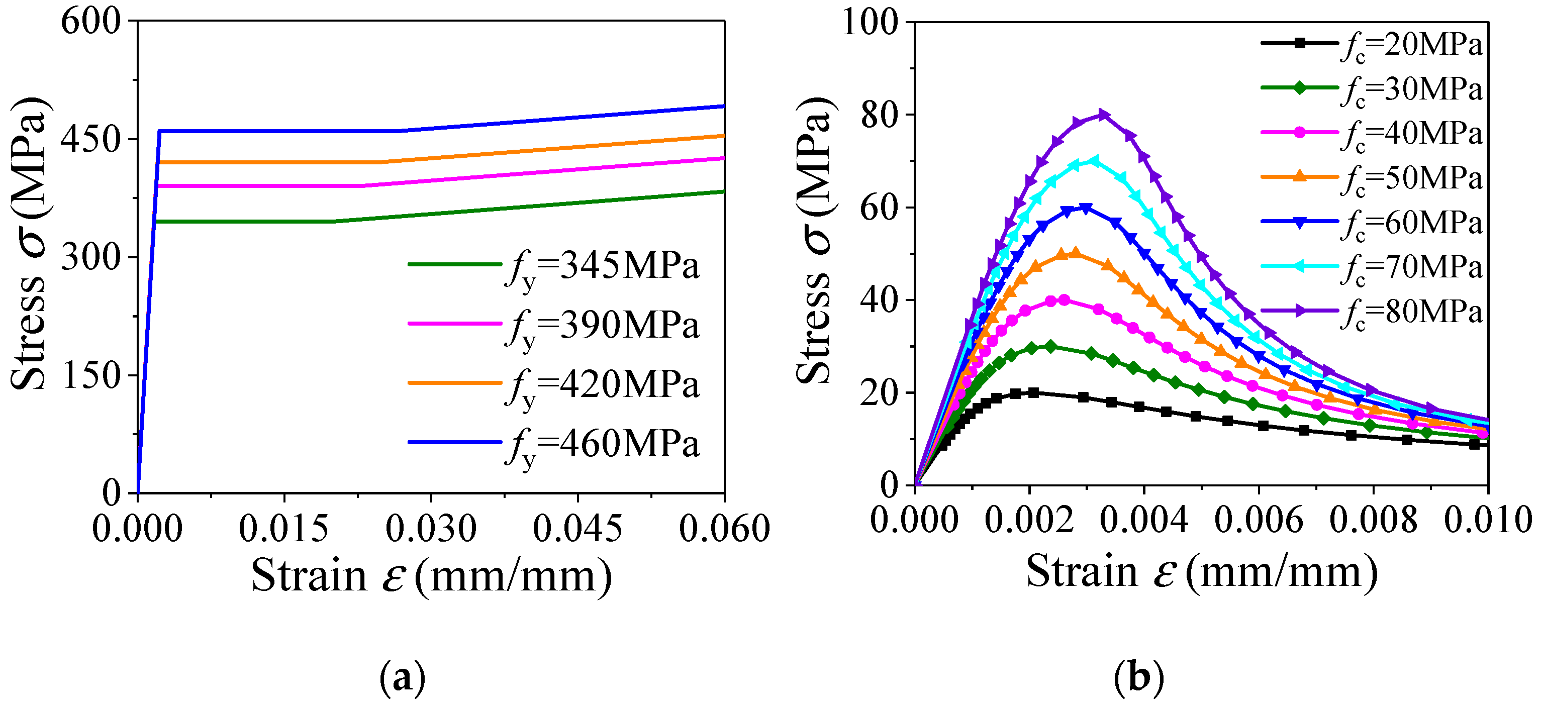
2.1. Constitutive Relation of the Steel Tube

An elastoplastic model incorporating the von Mises yield criteria, Prandtl–Reuss flow rule and isotropic strain hardening rule was used to describe the constitutive behaviors of the outer steel tube and loading plate. The expression of the constitutive stress–strain relationship of steel is described as follows [21]:
σ i = { E s ε i ε i ε y f y ε y ε i ε st f y + ζ E s ( ε i ε st ) ε st ε i ε u f u ε i > ε u
where σi and εi are the equivalent stress and strain of steel. fy and fu = 1.5 fy are the yield strength and ultimate strength of steel, respectively. Es= 2.06 × 10⁵ MPa is the elastic modulus of steel. εy, εst, εu are the yield strain, hardening strain and ultimate strain of steel, respectively, where εst is defined as 12 εy and εu is taken as 120 εy. The hardening parameter ζ is taken as 1/216. The detailed stress–strain curves are shown in Figure 1a.

2.2. Constitutive Relation of Lightweight Aggregate Concrete

A uniaxial constitutive model of LAC which is suitable for different LAC strengths, proposed by Ding et al. [22], was adopted for the simulation of infilled LAC in the presented study:
y = { A x + ( B 1 ) x 2 1 + ( A 2 ) x + B x 2 x 1 x α ( x 1 ) 2 + x x > 1
where y = σ/fc and x = ε/εc are the stress and strain ratios of LAC, respectively. σ and ε are the stress and strain of the infilled LAC. fc = 0.88 fcu is the uniaxial compressive strength of LAC, where fcu is the compressive cubic strength of LAC. εc is the strain corresponding with the peak compressive stress of LAC, where εc = 730 fcu1/3 × 10−6. The parameter A is the ratio of the initial tangent modulus to the secant modulus at peak stress and equals to 1.68 × 10⁻³ ρcfcu−1/6, where ρc is the bulk density of LAC. B = 5(A − 1)2/3 is a parameter that controls the decrease in the elastic modulus along the ascending branch of the axial stress–strain relationship. The stress–strain curves of LAC under uniaxial compression for several strength grades are shown in Figure 1b. For a LACFCST stub column, parameter α can be taken as 0.15. More detailed information of the LAC constitutive model under a tension state could be referred to in reference [22].

2.3. Element Type and Mesh Size

The FEMs of LACFCST stub column were established using the ABAQUS, version 6.14-4 [23]. In the FEMs, the 8-node reduced integral format 3D solid element (C3D8R) had three translational degrees of freedom per node, and was applied to simulate the steel tube, infilled LAC and loading plate [24]. The structured meshing technique in ABAQUS was adopted in this study, and the mesh size was approximately 50 mm, according to the dimensions of collected test specimens for the efficiency and accuracy. The typical mesh of the steel tube, infilled LAC and load plate are shown in Figure 2a,c, while the entire model of LACFCST columns is shown in Figure 2d.

2.4. Contact Interaction, Boundary Conditions and Loading

A “surface-to-surface” contact model was adopted for the simulation of interactions between the steel tube and infilled LAC/standard weight concrete (hereinafter referred to as infilled concrete), in which the inner surface of steel tube was selected as the master surface, and the external surface of the concrete was chosen as the slave surface. The limited slip was used in the sliding formulation, and the discretization method was “surface-to-surface”. Tangential behavior and normal behavior were defined as the contact property to simulate the interfacial bond–slip relationship between the steel tube and infilled concrete. The penalty function was utilized in the friction formula for the tangential behavior in which the friction coefficient was 0.5 [21,25], and the normal behavior was set to “hard” contact which allows separation after contact occurs. In ABAQUS, the tie connection can couple two separate surfaces so that no relative motion occurs between them; hence, the tie connection was adopted to connect the upper surface of the steel tube and infilled concrete to the bottom surface of the loading plate so that the axial load could be uniformly and simultaneously applied to the whole cross-section. The bottom surface of the loading plate was selected as the master surface while the top surface of the steel tube and infilled concrete was the slave surface.
The boundary condition of the column model is as follows: both ends of the stub column were fixed against all degrees of freedom except for the vertical displacement at the top end, as shown in Figure 3. The loading was applied in the manner of displacement control at the top center of the loading plate with a thickness of 20 mm.

2.5. Constitutive Model Parameter Settings

The tri-axial plastic-damage behaviors of the LAC in composite columns were defined in the Concrete Damaged Plasticity (CDP) model available in ABAQUS. The Poisson’s ratio of the LAC in the elastic stage is taken as 0.2; the eccentricity is 0.1; the ratio of the initial equibiaxial compressive yield stress to the initial uniaxial compressive yield stress (fb0/fc0) is 1.16; the ratio of the second stress invariant on the tensile meridian to that on the compressive meridian is 2/3; the viscosity parameter is 0.0005.
The dilation angle is a parameter that needs to be defined in the CDP model and has an evident impact on the simulated mechanical behaviors of infilled concrete in the composite columns [26]. In the existing numerical studies of CFST columns, the dilation angle of around 40° was the most selected [21]. However, this value may lead to inaccurate modeling of LACFCST columns due to the different confinement effect. Therefore, an investigation was performed to determine a rational value of LAC’s dilation angle by searching for the FE analysis results that best fit the test results. FE analyses on 49 specimens in references [14,15,27] with the dilation angles of 30°, 35°, and 40°, respectively, were carried out. The ultimate bearing capacities obtained from the FEMs analyses (Nu, FE) and test results (Nu, Exp) are shown in Figure 4 and Table 1. It can be seen that the average values of the ratios (Nu,Exp /Nu,FE) with the dilation angles of 30°, 35°, and 40° are 0.997, 0.947, and 0.923 with a coefficient of variation (C.V.) of 0.034, 0.042, and 0.045, respectively. In particular, the maximum deviation in these specimens is SC12-a, which has an ultimate bearing capacity of 721 kN in the experiment, and 790 kN, 871 kN, and 899 kN with the dilation angles of 30°, 35°, and 40° respectively. When the dilation angles were 30°, 35°, and 40°, the percentages of deviation were 9.6%, 20.8%, and 24.7% respectively. The comparison results indicated that the dilation angle of 30° best fit the test results of LACFCST stub columns.

2.6. Geometric Imperfection and Residual Stresses

Geometric imperfection is divided into overall geometric imperfection and local geometric imperfection. The geometric imperfection effect of the steel tube was considered in the FEMs of the LACFCST stub column under axial compression. When the first and fifteenth modes were obtained through the eigenvalue buckling analysis, these two modes were respectively introduced as the overall initial geometric imperfection and the local initial geometric imperfection of FEMs. Based on this kind of state, the non-linear FE analysis was run to obtain the ultimate compressive failure.
Residual stresses are generally present in the steel tube of the LACFCST stub column due to forming and welding. M. Ashraf et al. [28] and L. Gardner et al. [29] proved that the initial stiffness will be decreased slightly because of the residual stress in the steel tube, and it has little effect on the overall performance of the columns. Furthermore, the effect of residual stress will be further insignificant when working with the infilled concrete [30,31]. Therefore, the FEMs of LACFCST stub columns were established without considering the effect of residual stresses on the performance of the columns.

3. Finite Element Analysis

3.1. Model Validation

A total of 49 tested results from references [14,15,27] of LACFCST stub columns were collected. Correspondingly, a fine-meshed FEM analysis of the LACFCST stub columns under axial compression was performed for each specimen. The validity of the established models was verified against the experimental results. The ultimate bearing capacity of FE results was compared with the experimental results, and the ratio of test results to FE results (Nu,Exp/Nu, FE) are presented in Table 2. It was shown that the average value of the ratios (Nu,Exp/Nu, FE) is 0.997 with the corresponding C.V. of 0.034. It indicated that the ultimate bearing capacity obtained from the FE results and test results are in good agreement.
The typical axial load–axial strain curves of the FE results and experimental results of Fu [14] were compared and shown in Figure 5a. The distribution curves of the axial load undertaken by the steel tube (Nsε) and infilled concrete (Ncε), the stress–strain curve of steel and infilled concrete, the curve of the transverse deformation coefficient, defined as the absolute value of the ratio of the transverse strain to the axial strain, for the steel tube in specimen SC10-a are shown in Figure 5b. It can be found that, generally, good agreement is achieved between the calculated FE curves and the test curves. The comparison of these curves indicate that the established model of LACFCST stub columns under axial compression and the plastic-damage constitutive model of LAC adopted in this study can precisely reproduce the test results and accurately simulate the mechanical behaviors of LAC in composite columns.
The load–strain curves of the FE results and experimental results in Zhu [27] are compared in Figure 6a, and the experimental strain curves shown in the figure represent the average values of four measuring points. The ratio of the axial load to the ultimate load (N/Nu)—the transverse deformation coefficient curves—are presented in Figure 6b. Based on this comparison, it can be seen that the strain responses obtained by the FEMs coincide well with the experimental curves, which validate the applicability of the adopted elastoplastic constitutive model of steel tubes.

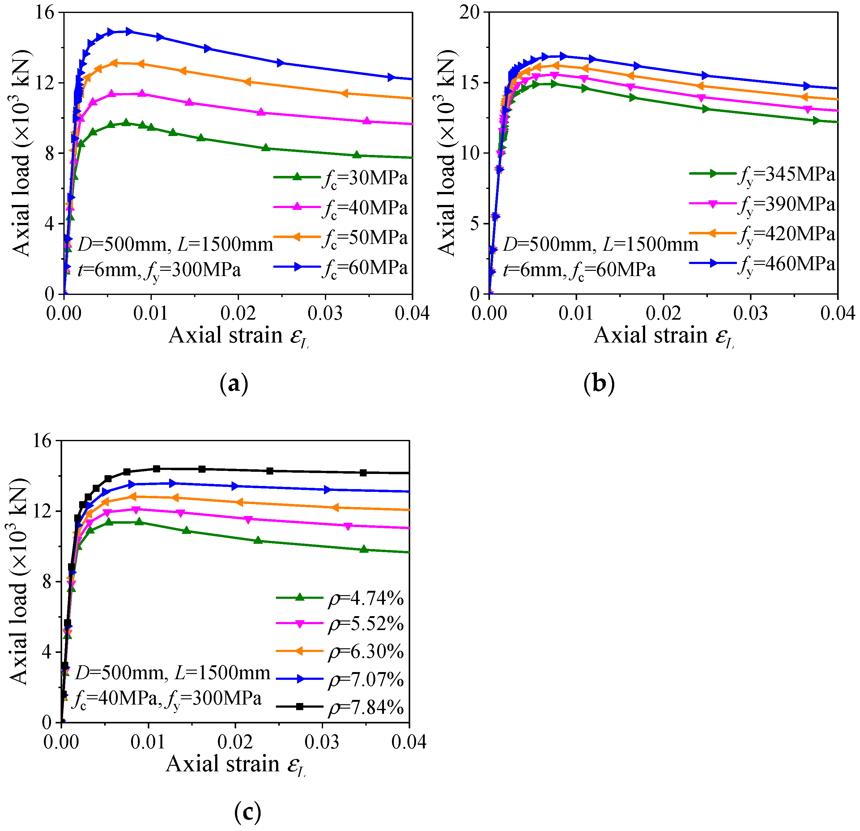
3.2. Parametric Study

With the validated FEM, a parametric study was conducted. A total of 95 full-scale FEMs were established to investigate the mechanical behaviors and composite actions of the LACFCST stub columns subjected to axial compression. The parameters of all specimens were taken as the outer diameter of circular section D = 500 mm, and the length of the column L = 1500 mm; the wall-thicknesses of the steel tubes were set as t = 6 mm, 7 mm, 8 mm, 9 mm, and 10 mm, with the steel ratios ρ of 4.74%, 5.52%, 6.30%, 7.07%, 7.84%, respectively. The elastic modulus Es was taken as 2.06 × 10⁵ MPa, and the yield strength fy of steel tube was taken as 235 MPa, 345 MPa, 390 MPa, 420 MPa, 460 MPa. The uniaxial compressive strength fc of LAC was selected as 20 MPa, 30 MPa, 40 MPa, 50 MPa, 60 MPa, 70 MPa and 80 MPa, which covered the available strength in engineering practice [32]. With different wall-thicknesses of steel tubes, the strength of carbon steel and LAC were paired according to the reasonable strength grade collocation for the LACFCST stub column specimens. As shown in Table 3, fy = 235 MPa was paired with fc = 20 MPa, 30 MPa, 40 MPa, 50 MPa; fy = 345 MPa was paired with fc = 30 MPa, 40 MPa, 50 MPa, 60 MPa, and so on.
The influence of the LAC strength, steel yield strength and steel ratio on the axial loading behaviors of the LACFCST stub columns are presented in Figure 7 in the manner of typical NFEεL curves. The presented results indicate that these factors have a significant impact on the ultimate bearing capacity of the LACFCST stub columns under axial compression. The influence trends of these parameters are similar to that of CFCST stub columns [19].

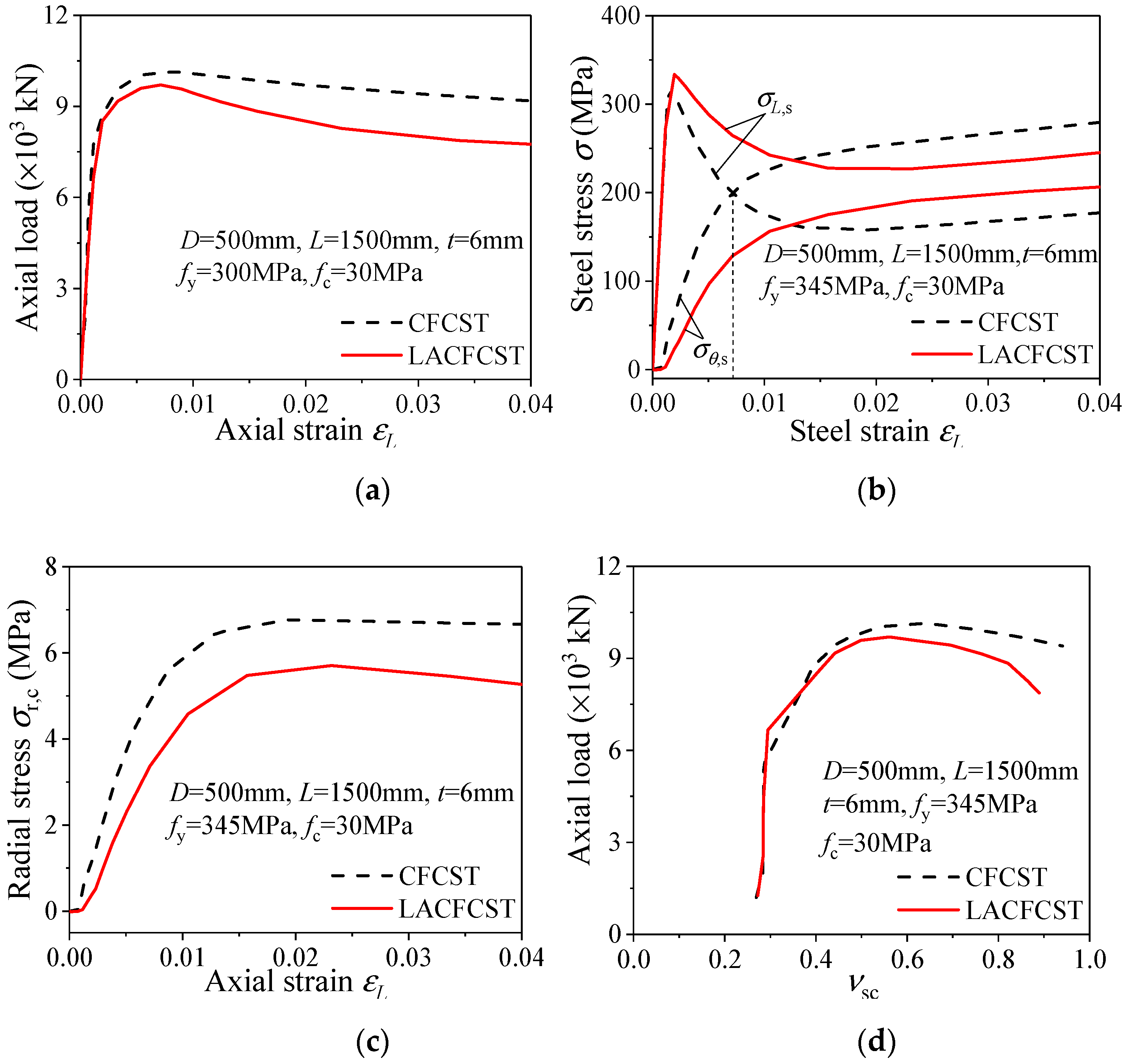
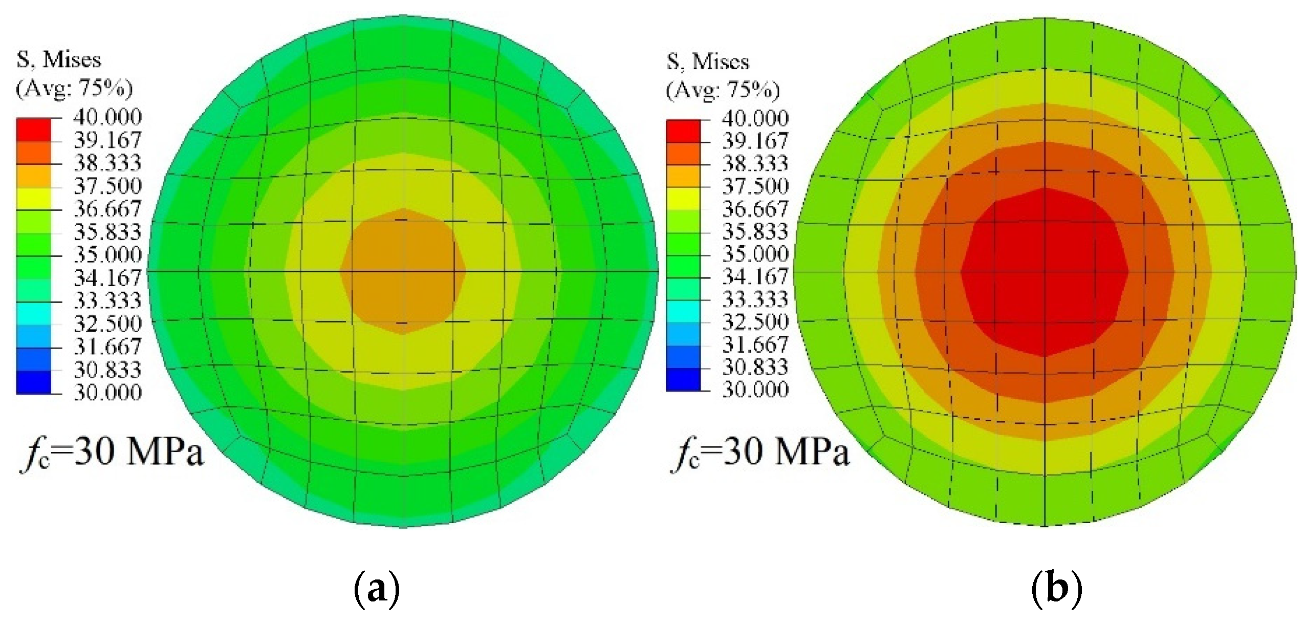
3.3. Comparison of CFCST and LACFCST Columns

To investigate the difference between the composite action of CFCST and LACFCST columns under the compressive load, a full-scale FEM of CFCST stub columns with the exact same design parameters was established. The composite actions between the outer steel tube and two types of infilled concretes were evaluated by comparing the structural responses, as shown in Figure 8a–d. The load–strain curves of LACFCST and CFCST stub columns are drawn in Figure 8a, and they indicate that the ultimate bearing capacity of LACFCST stub columns is slightly lower than that of CFCST stub columns with the same design parameters. In particular, the reduction is 4.6% in the presented case.
Under axial compression, the infilled LAC is confined by the steel tube while the tube is influenced by the infilled LAC, as well. From this point of view, the performance of the composite columns cannot be only evaluated by the confinement effect exerted by the out tube. Ding et al. [33] reported that in the CFST columns, the axial stress decreases with the increase in transverse stress in the elastoplastic element of the steel tube under axial compression. Given this behavior, the composite action in composite columns can be assessed by the variation in the axial and transverse stress of the steel tube during the loading process (Figure 8b). If the axial stress curves intersect with the transverse stress, the degree of composite action is high. Furthermore, if the intersection occurs earlier, the degree of composite action in the CFST columns is stronger. As shown in Figure 8b, the intersection point of CFCST appears at the strain level of 0.01, but there is no intersection point of the axial and transverse stress of the outer steel tube of LACFCST stub columns. Figure 8c shows that the radial stress–strain curves of infilled concrete in LACFCST stub columns and CFCST counterparts, and the load—the transverse deformation coefficient (Nνsc)—curves of the LACFCST stub column and CFCST stub column counterparts are plotted in Figure 8d. Given by Figure 8c,d, the radial stress of the LACFCST stub column is lower than that of CFCST stub column counterparts with the same axial strain level, and the load of the LACFCST stub column is lower than that of CFCST stub column counterparts with the same transverse deformation coefficient level, as well. These results revealed that the composite action between steel tubes and LAC is weaker than that between steel tubes and conventional concrete.

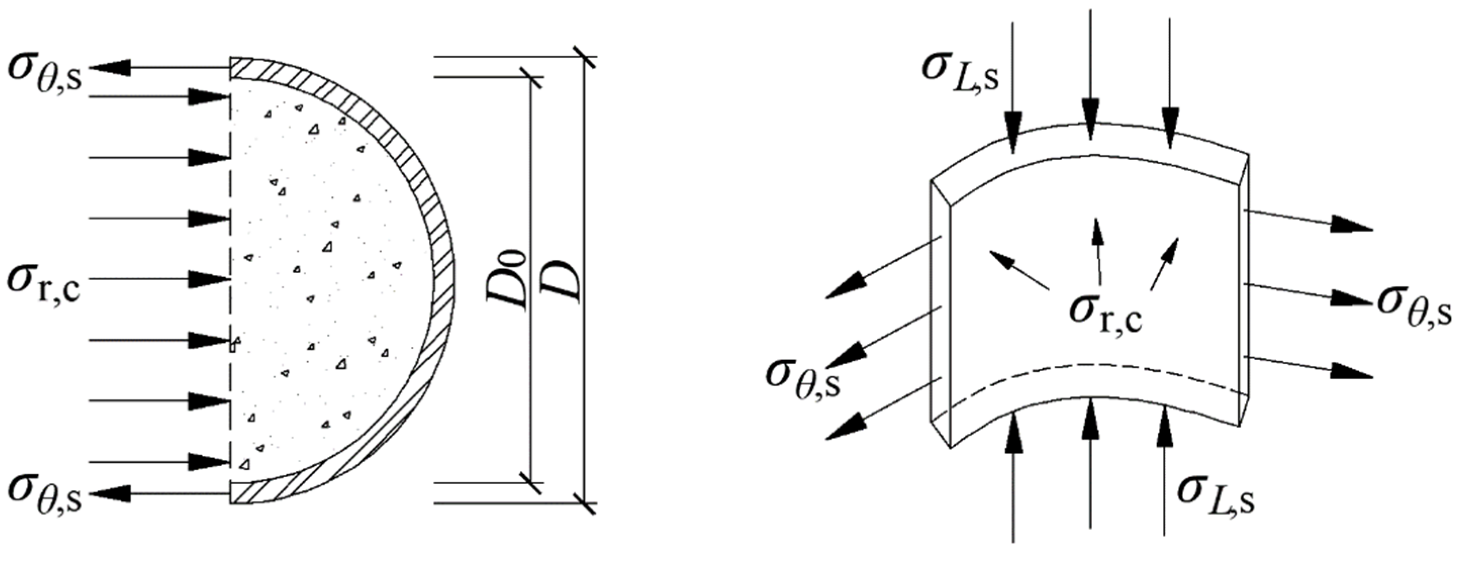
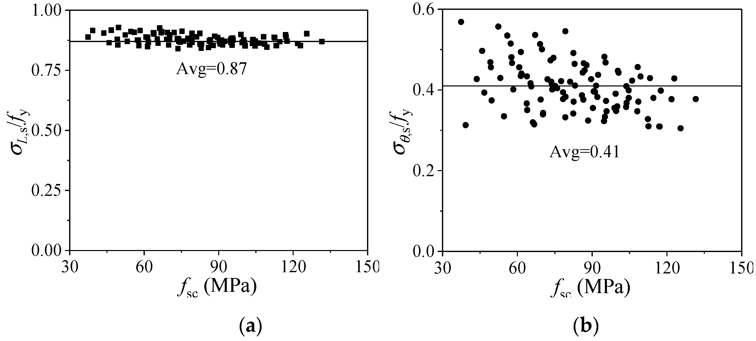
3.4. Composite Action Model of LACFCST Stub Columns

In the analytical modeling of axially-loaded CFST stub columns, the axial and transverse stress of steel tubes at the ultimate state are the key parameters to determine the load-bearing capacity. This is because the composite action between the steel tube and infilled concrete can be theoretically derived once these parameters are obtained. However, existing studies [5,34,35,36,37,38,39] assume that the von Mises yield criterion can be employed to define the ultimate state of the steel tube in composite columns:
σ L , s 2 + σ θ , s 2 σ L , s σ θ , s = f y 2
where σL,s and σθ,s represent the axial compressive stress and transverse tensile stress of the steel tube, respectively.
This may lead inaccurate prediction due to the following reasons. Firstly, based on the FE simulation, it is found that the metal tube may yield before or after the stub column reaches its ultimate state; in this situation, Equation (3) is invalid. Moreover, the stress component along the thickness direction is neglected, which means that Equation (3) is approximate, especially when the tube wall is thick. To compensate for this problem, the presented study extracts the axial and the transverse stress of the steel tube when the composite columns reach their ultimate state. Since the steel tube was modeled by the solid element, the three-dimensional stress state is considered.
The axial stress σL,s and the transverse stress σθ,s of the steel tube at the mid-height section of all the FEMs at the ultimate state were captured. It can be found from Figure 9 that the distribution of σL,s and σθ,s are highly correlated to the confinement factor ξ (ξ = Asfy/Acfc). Based on the FE analytical results, the numerical model of the composite action in LACFCST stub columns are proposed in Equations (4) and (5) using the regression method. It should be noticed here that two independent formulas were proposed for σL,s and σθ,s, respectively, instead of using Equation (3).
σ L , s / f y = 0.027 ξ + 0.8655
σ θ , s / f y = 0.1029 ln ( ξ ) + 0.4939

4. Practical Design Formula for the Load-Bearing Capacity of LACFCST Stub Columns

4.1. Model Simplification

The stress nephogram of infilled concrete of the mid-height section for LACFCST and CFCST stub columns was extracted from the FEMs and is presented in Figure 10. It indicates that the confinement effects of LACFCST and CFCST stub columns occur on the whole infilled concrete section and can be simplified in a method, as shown in Figure 11, where the steel tube in composite columns is subjected to multiple stresses under axial compression, in which D is the outer diameter of the steel tube, and D0 is the inner diameter of the steel tube, As is the sectional area of the steel tube, Ac is the sectional area of the whole infilled concrete, σr,c is the radial stress of concrete in the confined area, σθ,s is the transverse tensile stress of the steel tube, σL,s is the axial compressive stress of the steel tube, and ρ is the steel ratio.
According to the equilibrium condition of the stress state shown in Figure 11, the following equations can be obtained [40]:
σ r , c = ρ 2 ( 1 ρ ) σ θ , s
ρ = D 2 D 0 2 D 2

4.2. Formulation

Ding et al. [33] reported that the axial compressive stress (σL,c) of confined infilled concrete can be described as:
σ L , c = f c + k σ r , c
where k is the coefficient of lateral pressure according to the cross-section type, while for the circular section, k = 3.4.
On the basis of the static equilibrium method, the ultimate bearing capacity Nu of axially loaded LACFCST stub columns can be expressed as [34]:
N u = σ L , c A c + σ L , s A s
Substituting Equations (4)–(8) into Equation (9), the ultimate bearing capacity Nu1 can be obtained as:
N u 1 = f y A s ( 1 / ξ + 0.027 ξ + 0.1749 ln ( ξ ) + 1.7052 )
In the analytical study, when the specimen reached the ultimate state, the axial stress σL,s to yield strength fy ratio and the transverse stress σθ,s to yield strength fy ratio of the outer steel tube were calculated and are plotted in Figure 12 with the nominal average axial stress fsc (fsc = Nu/Asc, Asc = As + Ac) as the abscissa. Based on the analytical results of 95 specimens with different design parameters, it can be seen from Figure 12 that the average ratio of axial stress to yield strength is 0.87, which is greater than 0.69 of CFCST stub columns, and the average ratio of transverse stress to yield strength is 0.41, which is lower than 0.55 of CFCST stub columns [19].
To simplify the calculation process, the average ratio of σL,s/fy and σθ,s/fy can be employed instead of Equations (4) and (5). As shown in Figure 12a,b, when LACFCST stub columns reach the ultimate bearing capacity, the average ratio of axial compressive stress (σL,s) to yield strength, and transverse tensile stress (σθ,s) to yield strength of the steel tube can be obtained as:
σ L , s = 0.87 f y
σ θ , s = 0.41 f y
Substituting Equations (6)–(8) and Equations (11) and (12) into Equation (9), the ultimate bearing capacity Nu2 can be obtained as:
N u 2 = f c A c + K f y A s
where K is the enhancement factor [41], which reflects the enhancement effect provided by the infilled concrete to the outer tube. For LACFCST stub columns, K = 1.57 is slightly smaller than K = 1.62 of CFCST stub columns [19].

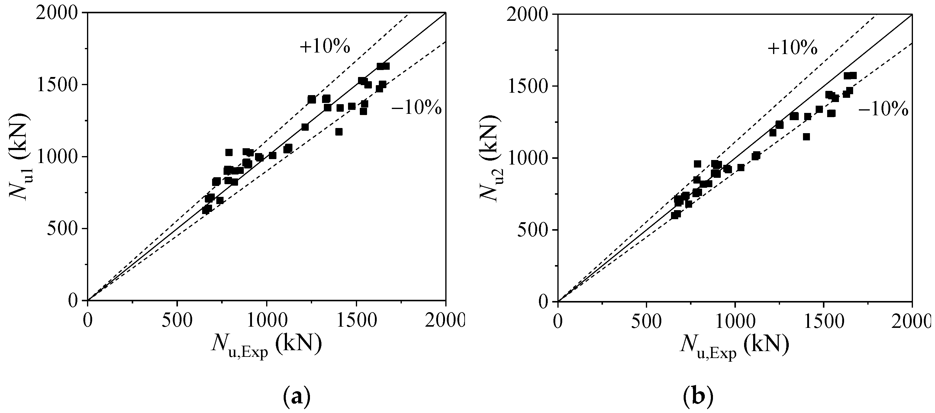
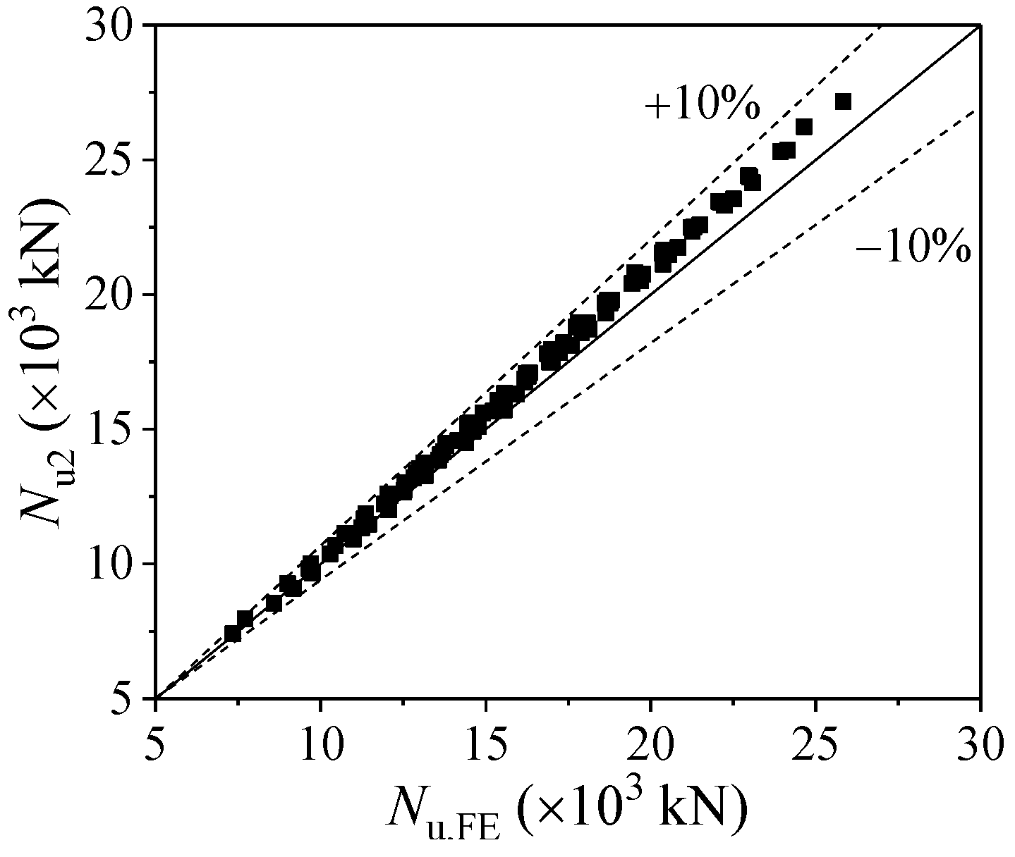
4.3. Formulas Validation

The ultimate bearing capacities calculated from Equation (10) (Nu1) and Equation (13) (Nu2) were compared with collected 49 experimental specimens results (Nu,Exp) in references [14,15,27], as shown in Figure 13. The average ratios of Nu1 and Nu2 to Nu, Exp is 1.031 and 0.967 with the corresponding C.V. of 0.092 and 0.072, respectively. The consequences of Equations (10) and (13) showed that there is nearly no difference using these two formulas to calculate the ultimate bearing capacity of the LACFCST stub columns. Equation (13) has a relatively conservative calculation result and a simple form, which is beneficial to its application in practical engineering.
The ultimate bearing capacities of 95 full-scale FEMs, calculated from Equation (13) (Nu2), and FE results (Nu, FE) were compared, as shown in Figure 14. The average ratio of Nu2 to Nu, FE is 1.038 with the corresponding C.V. of 0.018, which means the FEM analytical results and the proposed Equation (13) have good agreement.
To evaluate the performance of the proposed design equation, three methods, suggested by the current design codes for the normal strength CFCST stub columns as shown in Table 4, were used to calculate the bearing capacity of the collected 49 experimental specimens in references [14,15,27]. Those widely used design codes employed in this study, include the GB 50936 [42] for China, the EC 4 [11] for Europe and ACI-318 [12] for the United States. The results, Nu2, NGB, NEC, and NACI, calculated by the proposed Equation (13) and three codes, respectively, are listed in Figure 15 and Table 5. It can be seen from Table 5 that the average values of the ratios (Nu2/Nu,Exp, NGB/Nu,Exp, NEC/Nu,Exp, and NACI/Nu,Exp) are 0.967, 1.009, 0.933, 0.729 with a C.V. of 0.072, 0.088, 0.086, and 0.079 respectively. The results revealed that the accuracy of the proposed equation is comparable to GB 50,936 [42] and EC 4 [11], and higher than that of ACI-318 [12]. On the other hand, the formula proposed in this paper is simple, and its physical meaning is clear.

5. Conclusions

The objective of this paper is to investigate the confinement effects of LACFCST stub columns under axial loading. The main findings are summarized as follows:
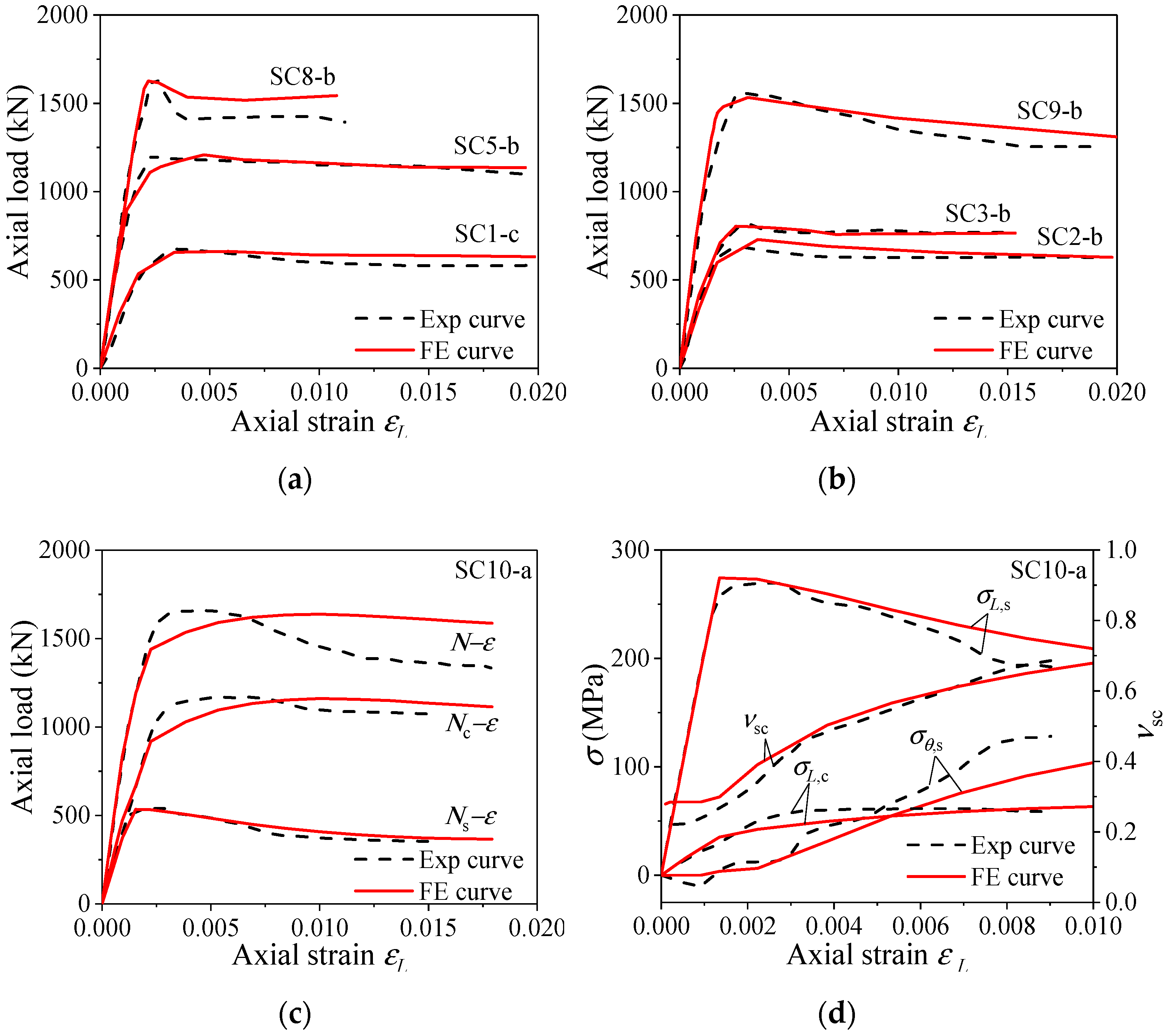
  • Using a plastic-damage constitutive model of LAC and an elastoplastic model with isotropic strain hardening of the steel tube, a fine-meshed finite 3D solid element model of the LACFCST stub column was established in ABAQUS. The validity of the established FEM was verified against the test results of the ultimate bearing capacity and strain responses of the steel tube, and the load-shortening curves.
  • A total of 95 full-scale FEMs, using the abovementioned FE modeling method, were established for the parametric study. The analytical results revealed that the composite action in LACFCST stub columns is weaker than that in CFST stub columns.
  • Regression models of the axial and transverse stress of the outer steel tube at the ultimate state of the columns were proposed, respectively. This model considered the three-dimensional stress state of the outer tube and is a more authentic expression when the column reaches its ultimate state.
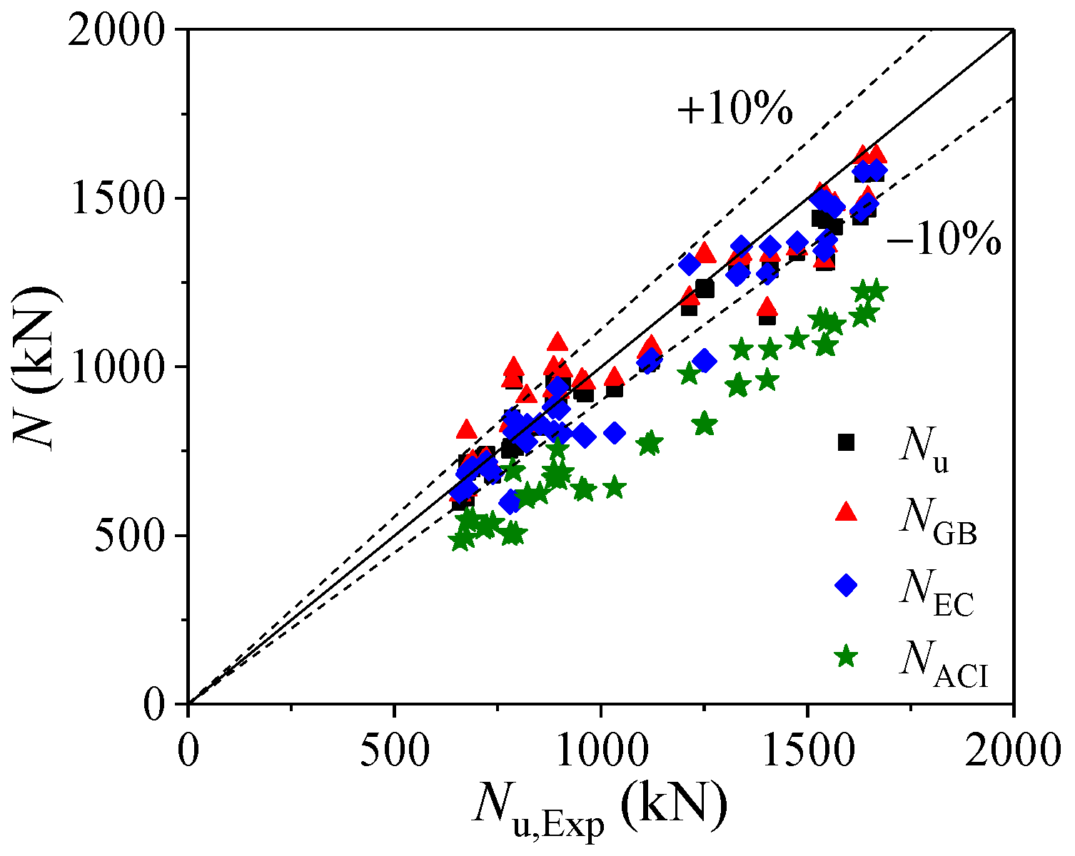
  • A design formula of ultimate bearing capacity of LACFCST stub columns under axial loading was derived based on the proposed composite action model. A simplified formula using an enhancement factor was proposed as well. The derived enhancement factor of LACFCST stub columns is 1.57, which is slightly smaller than 1.62 of CFCST stub columns. The proposed formula was verified as more accurate and concise than current design methods.

Author Contributions

Conceptualization, Y.X., F.L., and F.D.; methodology, F.D., and F.L.; software, Y.X.; validation, C.L.; formal analysis, C.L.; data curation, F.L., and Y.X.; writing—original draft preparation, Y.X.; writing—review and editing, E.W.; supervision, F.D.; funding acquisition, F.D. All authors have read and agreed to the published version of the manuscript.

Funding

This research was funded by the National Natural Science Foundation of China (No. 51978664) and the Natural Science Foundation of Hunan Province for Distinguished Young Scholars (No. 2019JJ20029).

Institutional Review Board Statement

Not applicable.

Informed Consent Statement

Not applicable.

Data Availability Statement

The data used to support the findings of this study are obtained directly from the simulation by all authors.

Conflicts of Interest

The authors declare no conflict of interest.

Nomenclature

AcCross-sectional area of infilled concrete
AsCross-sectional area of steel tube
AscCross-sectional area of LACFCST column
DOuter diameter of steel tube
D0Inner diameter of steel tube
EsElastic modulus of steel tube
fcUniaxial compressive strength of LAC
fcuCompressive cubic strength of LAC
fscNominal average axial stress
fuUltimate strength of steel tube
fyYield strength of steel tube
KEnhancement factor
LLength of column specimen
NACIUltimate bearing capacity calculated by ACI-318
NECUltimate bearing capacity calculated by EC 4
NGBUltimate bearing capacity calculated by GB 50936
NuUltimate bearing capacity of stub columns
Nu,ExpUltimate bearing capacity obtained from test
Nu,FEUltimate bearing capacity obtained from FEMs
tWall-thickness of steel tube
ξConfinement factor
ρSteel ratio of LACFCST column
εcStrain at the peak compressive stress
εLLongitudinal strain of steel tube
εstHardening strain of steel tube
εuUltimate strain of steel tube
εyYield strain of steel tube
σL,cAxial compressive stress of infilled concrete
σL,sAxial compressive stress of steel tube
σr,cRadial stress of infilled concrete
σθ,sTransverse tensile stress of steel tube
νscTransverse deformation coefficient

References

  1. Ghazijahani, T.G.; Jiao, H.; Holloway, D. Rectangular steel tubes with timber infill and CFRP confinement under compression: Experiments. J. Constr. Steel Res. 2015, 114, 196–203. [Google Scholar] [CrossRef]
  2. Assi, I.M.; Qudeimat, E.M.; Hunaiti, Y.M. Ultimate moment capacity of foamed and lightweight aggregate concrete-filled steel tubes. Steel Compos. Struct. 2003, 3, 199–212. [Google Scholar] [CrossRef]
  3. Mouli, M.; Khelafi, H. Strength of short composite rectangular hollow section columns filled with lightweight aggregate concrete. Eng. Struct. 2007, 29, 1791–1797. [Google Scholar] [CrossRef]
  4. Cui, H.; Lo, T.Y.; Memon, S.A.; Xu, W. Effect of lightweight aggregates on the mechanical properties and brittleness of lightweight aggregate concrete. Constr. Build. Mater. 2012, 35, 149–158. [Google Scholar] [CrossRef]
  5. Elremaily, A.; Azizinamini, A. Behavior and strength of circular concrete-filled tube columns. J. Constr. Steel Res. 2002, 58, 1567–1591. [Google Scholar] [CrossRef]
  6. Ding, F.; Wang, W.; Liu, X.; Wang, L.; Sun, Y. Mechanical behavior of outer square inner circular concrete-filled dual steel tubular stub columns. Steel Compos. Struct. 2021, 38, 305–317. [Google Scholar] [CrossRef]
  7. Gupta, P.K.; Ahuja, A.K.; Khaudhair, Z.A. Modelling, verification and investigation of behaviour of circular CFST columns. Struct. Concr. 2014, 15, 340–349. [Google Scholar] [CrossRef]
  8. Ghannam, S.; Jawad, Y.A.; Hunaiti, Y. Failure of lightweight aggregate concrete-filled steel tubular columns. Steel Compos. Struct. 2004, 4, 1–8. [Google Scholar] [CrossRef] [Green Version]
  9. Abhilash, M.; Jhanjhari, S.; Parthiban, P.; Karthikeyan, J. Axial behaviour of semi-lightweight aggregate concrete-filled steel tube columns—A DOE approach. J. Constr. Steel Res. 2019, 162, 105614. [Google Scholar] [CrossRef]
  10. Salgar, P.B.; Patil, P.S. Experimental Investigation on Behavior of High-Strength Light weight Concrete-Filled Steel Tube Strut Under Axial Compression. INAE Lett. 2019, 4, 207–214. [Google Scholar] [CrossRef]
  11. European Committee for Standardization. EUROCODE 4. Design of Steel Composite Steel and Concrete Structures; Part 1-1, General Rules and Rules for Building, BS EN 1994-1-1; British Standards Institution: London, UK, 2004. [Google Scholar]
  12. American Concrete Institute. ACI-318-11. Building Code Requirements for Structural Concrete and Commentary ACI Committee 318; American Concrete Institute: Detroit, MI, USA, 2011. [Google Scholar]
  13. Zhang, X.; Kuang, X.; Yang, J.; Fan, Y. Bearing Capacity of Stone-Lightweight Aggregate Concrete-Filled Steel Tubular Stub Column Subjected to Axial Compression. KSCE J. Civ. Eng. 2019, 23, 3122–3134. [Google Scholar] [CrossRef]
  14. Fu, Z.; Ji, B.; Zhou, Y.; Wang, X. An experimental behavior of lightweight aggregate concrete filled steel tubular stub under axial compression. Geotech. Spec. Publ. ASCE 2011, 219, 24–32. [Google Scholar] [CrossRef]
  15. Yang, M. Research on the Behavior of Core Lightweight Aggregate Concrete under the Confinement of Steel Tube. Master’s Thesis, Hohai University, Nanjing, China, 2006. [Google Scholar] [CrossRef]
  16. Fu, Z.Q.; Ji, B.H.; Ge, H.B.; Yang, M. Combined strength of lightweight aggregate concrete-filled steel tube. Mater. Res. Innov. 2015, 19, 5–898. [Google Scholar] [CrossRef]
  17. Fu, Z.; Ge, H.; Ji, B.; Chen, J. Interface bond behaviour between circular steel tube and lightweight aggregate concrete. Adv. Steel Constr. 2018, 14, 424–437. [Google Scholar] [CrossRef] [Green Version]
  18. Gao, C.Y.; Li, B. Experimental Research on Seismic Behavior for Lightweight Aggregate Concrete-Filled Steel Tubular Frame. Adv. Mater. Res. 2010, 163–167, 2194–2198. [Google Scholar] [CrossRef]
  19. Ding, F.-X.; Yin, Y.-X.; Mao, J.-F.; Wang, L.-P.; Yu, Y.-J.; Luo, L.; Yu, Z.-W. Analytical behaviors of concrete-filled circular stainless steel tubular (CFCSST) stub columns under axial loading. Structures 2019, 19, 277–285. [Google Scholar] [CrossRef]
  20. Ding, F.; Yin, Y.; Wang, L.; Yu, Y.; Luo, L.; Yu, Z. Confinement coefficient of concrete-filled square stainless steel tubular stub columns. Steel Compos. Struct. 2019, 30, 337–350. [Google Scholar] [CrossRef]
  21. Ding, F.; Ying, X.; Zhou, L.; Yu, Z. Unified calculation method and its application in determining the uniaxial mechanical properties of concrete. Front. Arch. Civ. Eng. China 2011, 5, 381–393. [Google Scholar] [CrossRef]
  22. Ding, F.; Ying, X.; Yu, Z. Unified calculation method of uniaxial mechanical properties of lightweight aggregate concrete. J. Cent. South. Univ. 2010, 41, 1973–1979. Available online: https://www.researchgate.net/publication/291828442_Unified_calculation_method_of_uniaxial_mechanical_properties_of_lightweight_aggregate_concrete (accessed on 22 April 2021). (In Chinese).
  23. ABAQUS. ABAQUS Standard User’s Manual, Version 6.14; Dassault Systèmes Simulia Corp: Providence, RI, USA, 2014. [Google Scholar]
  24. ABAQUS. ABAQUS Analysis User’s Manual, Volume IV: Elements; Dassault Systèmes Simulia Corp: Providence, RI, USA, 2014. [Google Scholar]
  25. Zhang, T.; Ding, F.; Wang, L.; Liu, X.; Jiang, G. Behavior of polygonal concrete-filled steel tubular stub columns under axial loading. Steel Compos. Struct. 2018, 28, 573–588. [Google Scholar] [CrossRef]
  26. Wosatko, A.; Winnicki, A.; Polak, M.A.; Pamin, J. Role of dilatancy angle in plasticity-based models of concrete. Arch. Civ. Mech. Eng. 2019, 19, 1268–1283. [Google Scholar] [CrossRef]
  27. Zhu, Z. Research on Behaviour of Lightweight Aggregate Concrete-Filled Thin-Walled Steel Tube Columns under Compression. Master’s Thesis, Guangxi University, Nanning, China, 2019. [Google Scholar]
  28. Ashraf, M.; Gardner, L.; Nethercot, D.A. Finite element modelling of structural stainless steel cross-sections. Thin Walled Struct. 2006, 44, 1048–1062. [Google Scholar] [CrossRef]
  29. Gardner, L.; Nethercot, D.A. Numerical Modeling of Stainless Steel Structural Components—A Consistent Approach. J. Struct. Eng. 2004, 130, 1586–1601. [Google Scholar] [CrossRef]
  30. Tao, Z.; Uy, B.; Liao, F.-Y.; Han, L.-H. Nonlinear analysis of concrete-filled square stainless steel stub columns under axial compression. J. Constr. Steel Res. 2011, 67, 1719–1732. [Google Scholar] [CrossRef]
  31. Ellobody, E.; Young, B. Structural performance of cold-formed high strength stainless steel columns. J. Constr. Steel Res. 2005, 61, 1631–1649. [Google Scholar] [CrossRef]
  32. Zhao, T. Study on Uniaxial Compressive Behavior of High Strength Lightweight Aggregate Concrete. Master’s Thesis, Chang’an University, Xi’an, China, 2017. [Google Scholar]
  33. Ding, F.-X.; Yu, Z.-W.; Bai, Y.; Gong, Y.-Z. Elasto-plastic analysis of circular concrete-filled steel tube stub columns. J. Constr. Steel Res. 2011, 67, 1567–1577. [Google Scholar] [CrossRef]
  34. Yu, F.; Fang, Y.; Zhang, Y.; Xu, L.; Bai, R. Mechanical behavior of self-stressing steel slag aggregate concrete filled steel tubular stub columns. Struct. Concr. 2020, 21, 1597–1611. [Google Scholar] [CrossRef]
  35. Sakino, K.; Nakahara, H.; Morino, S.; Nishiyama, I. Behavior of Centrally Loaded Concrete-Filled Steel-Tube Short Columns. J. Struct. Eng. 2004, 130, 180–188. [Google Scholar] [CrossRef]
  36. Hatzigeorgiou, G.D. Numerical model for the behavior and capacity of circular CFT columns, Part II: Verification and extension. Eng. Struct. 2008, 30, 1579–1589. [Google Scholar] [CrossRef]
  37. Liu, J.; Zhang, S.; Zhang, X.; Guo, L. Behavior and strength of circular tube confined reinforced-concrete (CTRC) columns. J. Constr. Steel Res. 2009, 65, 1447–1458. [Google Scholar] [CrossRef]
  38. Shirakawa, M.A.; John, V.M.; Gaylarde, C.C.; Gaylarde, P.; Gambale, W. Mould and phototroph growth on masonry façades after repainting. Mater. Struct. 2004, 37, 472–479. [Google Scholar] [CrossRef]
  39. Taha, M.M.R.; El-Dieb, A.S.; Shrive, N.G. Sorptivity: A reliable measurement for surface absorption of masonry brick units. Mater. Struct. 2001, 34, 438–445. [Google Scholar] [CrossRef]
  40. Lu, D.-R.; Wang, W.-J.; Ding, F.-X.; Liu, X.-M.; Fang, C.-J. The impact of stirrups on the composite action of concrete-filled steel tubular stub columns under axial loading. Structures 2021, 30, 786–802. [Google Scholar] [CrossRef]
  41. Wei, Y.; Jiang, C.; Wu, Y.-F. Confinement effectiveness of circular concrete-filled steel tubular columns under axial compression. J. Constr. Steel Res. 2019, 158, 15–27. [Google Scholar] [CrossRef]
  42. GB 50936-2014. Technical Code for Concrete-Filled Steel Tubular Structures; China Architecture & Building Press: Beijing, China, 2014.
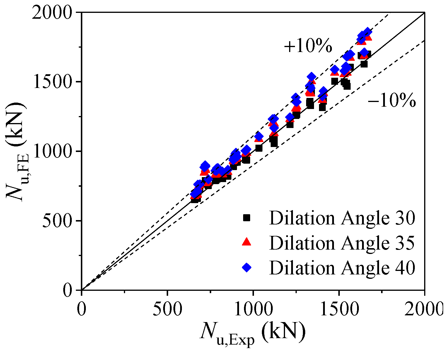
Figure 1. Stress–strain curves of steel tube and LAC: (a) steel tube; (b) LAC.
Mathematics 09 00948 g001
Figure 2. Mesh of the FEMs: (a) steel tube; (b) core concrete; (c) loading plate; (d) whole model.
Mathematics 09 00948 g002
Figure 3. Boundary conditions of the FEMs.
Mathematics 09 00948 g003
Figure 4. The ultimate bearing capacities obtained from tests and FEMs with different dilation angles.
Mathematics 09 00948 g004
Figure 5. Comparison of FE and experimental curves about Fu [14]: (a) comparison of load–strain curves of SC1-c, SC5-b and SC8-b; (b) comparison of load–strain curves of SC2-b, SC3-b and SC9-b; (c) comparison of load–strain curves of SC10-a; (d) comparison of stress–strain curves of SC10-a.
Mathematics 09 00948 g005
Figure 6. Comparison of FE and experimental curves about Zhu [27]: (a) comparison of load–strain curves of SC1-1-1a and SC1-1-2a; (b) comparison of load–strain curves of SC1-2-1a and SC1-2-2a; (c) comparison of load ratio–strain ratio curves of SC1-1-1a; (d) comparison of load ratio–strain ratio curves of SC1-1-2a.
Mathematics 09 00948 g006
Figure 7. Influence of various parameters on the load-bearing capacity: (a) concrete strength; (b) steel yielding strength; (c) steel ratio.
Mathematics 09 00948 g007
Figure 8. Comparison of typical curves for LACFCST and CFCST stub columns: (a) load–strain curves; (b) stress–strain curves of steel tubes; (c) radial stress–strain curves of core concrete; (d) load–strain ratio curves of steel tubes.
Mathematics 09 00948 g008
Figure 9. Influence of ξ on outer steel tubular stress: (a) the axial stress of outer steel tube; (b) the transverse stress of outer steel tube.
Mathematics 09 00948 g009
Figure 10. Comparison of stress nephogram at mid-height section for LACFCST and CFCST stub columns: (a) LACFCST stub column; (b) CFCST stub column.
Mathematics 09 00948 g010
Figure 11. Simplified stress distribution model at the mid-height section of LACFCST stub columns.
Mathematics 09 00948 g011
Figure 12. Analytical results of axial stress and transverse stress of outer steel tube of LACFCST stub column: (a) average ratio of axial stress to yield strength of steel tubes; (b) average ratio of transverse stress to yield strength of steel tubes.
Mathematics 09 00948 g012
Figure 13. Comparison of Equations (10) and (13): (a) comparison of the ultimate bearing capacities obtained from test results and Equation (10); (b) comparison of the ultimate bearing capacities obtained from test results and Equation (13).
Mathematics 09 00948 g013
Figure 14. Comparison of the ultimate bearing capacities obtained from FE results and Equation (13).
Mathematics 09 00948 g014
Figure 15. Comparison of the ultimate bearing capacities obtained from test results and equations.
Mathematics 09 00948 g015
Table 1. Comparison of average ratio with different dilation angle.
Dilation Angle30°35°40°
Average ratio (Nu,Exp/Nu,FE)0.9970.9470.923
C.V.0.0340.0420.045
Table 2. Specimen details and comparisons of load-bearing capacities obtained from FEM and Exp.
SpecimensRef.D × t × L (mm)Ec (MPa)fc (MPa)fy (MPa)Nu,Exp (kN)Nu,FE (kN)Nu,Exp/Nu,FE
SC1-a[14]111.2 × 2.04 × 34223,84029.21305.66596511.013
SC1-c111.5 × 2.11 × 34223,84029.21305.66756611.021
SC2-a111.4 × 2.06 × 34224,83037.66305.67387520.982
SC2-b111.4 × 2.19 × 34224,83037.66305.66897290.945
SC2-c111.3 × 2.12 × 34224,83037.66305.66787080.957
SC3-a113.5 × 3.79 × 34223,84029.21274.78528211.038
SC3-b113.4 × 3.78 × 34223,84029.21274.78228041.023
SC4-a113.3 × 3.79 × 34224,83037.66274.78849090.972
SC4-b113.4 × 3.81 × 34224,83037.66274.78899200.966
SC4-c113.3 × 3.75 × 34224,83037.66274.78999420.954
SC5-b164.5 × 2.64 × 49523,84029.21281.7121411921.018
SC5-c164.4 × 2.51 × 49523,84029.21281.7140313151.067
SC6-a164.3 × 2.63 × 49524,83037.66281.7147515030.981
SC6-c164.8 × 2.45 × 49524,83037.66281.7154014861.036
SC7-a165.5 × 2.99 × 49523,84029.21293.9141013601.037
SC7-b165.2 × 3.01 × 49523,84029.21293.9134014210.943
SC7-c165.2 × 3.11 × 49523,84029.21293.9154714661.055
SC8-b164.5 × 3.11 × 49524,83037.66293.9164716261.013
SC8-c165.0 × 2.96 × 49524,83037.66293.9162916890.964
SC9-a165.2 × 3.98 × 49523,84029.21275.8153014991.021
SC9-b164.8 × 3.88 × 49523,84029.21275.8156616030.977
SC9-c165.0 × 3.96 × 49523,84029.21275.8154514891.038
SC10-a164.7 × 3.86 × 49524,83037.66275.8166716990.981
SC10-b164.5 × 3.86 × 49524,83037.66275.8163416850.970
SC11-a163.9 × 2.47 × 49519,50022.9281.7111310901.021
SC11-b163.9 × 2.53 × 49519,50022.9281.7112311011.020
SC11-c164.4 × 2.49 × 49519,50022.9281.7112210551.064
SC12-a113.3 × 3.59 × 34219,50022.9274.77217900.913
SC12-b113.5 × 3.60 × 34219,50022.9274.77237620.949
SC12-c113.1 × 3.56 × 34219,50022.9274.77157660.933
SC13-a164.5 × 3.90 × 49519,50022.9275.8133513291.005
SC13-b164.3 × 3.88 × 49519,50022.9275.8132913470.986
SC13-c164.6 × 3.87 × 49519,50022.9275.8133113570.981
SC1-A[15]163.9 × 2.47 × 49518,50016.7299.09629361.028
SC1-B164.0 × 2.53 × 49518,50016.7299.0103310221.011
SC1-C164.4 × 2.49 × 49518,50016.7299.09549391.016
SC2-A113.4 × 3.57 × 34224,80039.3315.07897990.987
SC2-B113.3 × 3.60 × 34224,80039.3315.08868900.996
SC2-C113.0 × 3.58 × 34224,80039.3315.09079200.986
SC3-A113.5 × 3.60 × 34218,50016.7315.07827910.989
SC3-B113.1 × 3.56 × 34218,50016.7315.07797890.987
SC3-C113.3 × 3.60 × 34218,50016.7315.07948050.986
SC4-A164.5 × 3.90 × 49518,50016.7295.2125112620.991
SC4-B164.3 × 3.88 × 49518,50016.7295.2125412650.991
SC4-C164.6 × 3.87 × 49518,50016.7295.2124812580.992
SC1-1-1a[27]165.0 × 1.32 × 57819,60022.9226.76756651.015
SC1-1-2a165.0 × 2.05 × 57819,60022.9214.18208061.017
SC1-2-1a165.0 × 1.32 × 57723,40029.3226.77858010.980
SC1-2-2a165.0 × 2.05 × 57723,40029.3214.18959180.975
Mean-------0.997
C.V.-------0.034
Table 3. Parameters of specimens for FE parametric study.
D (mm)L (mm)Es (MPa)t (mm)fy (MPa)fc (MPa)
500150020, 600, 06, 7, 8, 9, 1023520, 30, 40, 50
34530, 40, 50, 60
39040, 50, 60, 70
42050, 60, 70, 80
46060, 70, 80
Table 4. Summary of available formulas in well-known national codes.
ReferencesFormulasAddition
GB 50936 (2014) [42]When θ 1 / ( α 1 ) 2 , N GB = 0.9 A c f c ( 1 + α θ ) ;
When θ > 1 / ( α 1 ) 2 , N GB = 0.9 A c f c ( 1 + θ + θ )
θ = A s f y A c f c
If fcu ≤ 50 MPa, α = 2.0
If 50 MPa ≤ fcu ≤ 80 MPa, α = 1.8
EC 4 (2004) [11] N EC 4 = η α f y A s + f c A c ( 1 + η c t f y D f c ) η α = 0.25 ( 3 + 2 λ ¯ ) 1.0
η c = 4.9 18.5 λ ¯ + 17 λ ¯ 2 1.0
λ ¯ = N pl , Rk N cr , N pl , Rk = σ 0.2 A s + f c A c
N cr = π 2 ( E s I s + 0.6 E c I c ) L 2
ACI-318 (2011) [12] N ACI = f y A s + 0.85 f c A c
Table 5. Comparison between experimental and predicted results using different design methods.
SpecimensRef.Nu2 (kN)NGB (kN)NEC (kN)NACI (kN)Nu,Exp (kN)Nu2/
Nu,Exp
NGB/
Nu,Exp
NEC/
Nu,Exp
NACI/
Nu,Exp
SC1-a[14]5996226274856590.9090.9430.9510.737
SC1-c6126376394946750.9070.9430.9470.732
SC2-a6806966855377380.9210.9430.9280.728
SC2-b6997187025496891.0151.0421.0190.797
SC2-c6887056925426781.0151.0401.0200.799
SC3-a8218288306248520.9630.9720.9750.733
SC3-b8188268286238220.9961.0051.0070.758
SC4-a8939308796708841.0101.0520.9940.758
SC4-b8979338836728891.0091.0490.9930.756
SC4-c8889258746678990.9871.0290.9730.742
SC5-b11751204130497812140.9680.9921.0740.806
SC5-c11471172127696114030.8180.8350.9090.685
SC6-a133913511370108214750.9080.9160.9290.733
SC6-c130913141344106515400.8500.8530.8730.692
SC7-a128813331357105114100.9140.9450.9620.745
SC7-b128913351357105013400.9620.9961.0130.784
SC7-c131113601377106415470.8470.8790.8900.688
SC8-b146915011483116216470.8920.9110.9000.706
SC8-c144414711462114916290.8860.9030.8970.705
SC9-a144015111498114115300.9410.9880.9790.746
SC9-b141514831474112515660.9040.9470.9410.718
SC9-c143415041491113715450.9280.9730.9650.736
SC10-a157316241583122516670.9440.9740.9490.735
SC10-b157116211579122316340.9610.9920.9670.748
SC11-a10081044101276811130.9060.9380.9090.690
SC11-b10211059102477611230.9090.9430.9120.691
SC11-c10171054102177411220.9070.9390.9100.690
SC12-a7367247165257211.0211.0050.9930.728
SC12-b7397277195277231.0231.0060.9940.729
SC12-c7307197105217151.0211.0060.9930.729
SC13-a12941327127894613350.9690.9940.9570.709
SC13-b12871321127194213290.9690.9940.9570.709
SC13-c12891323127394313310.9680.9940.9570.709
SC1-A[15]9199527936339620.9560.9900.8240.658
SC1-B93496480464210330.9040.9340.7780.622
SC1-C9289618006399540.9731.0070.8390.670
SC2-A9589948076907891.2141.2601.0220.875
SC2-B9619968086928861.0851.1240.9120.781
SC2-C9549908036879071.0521.0910.8850.758
SC3-A7638386045077820.9761.0720.7720.649
SC3-B7538275965017790.9671.0620.7660.643
SC3-C7618366025067940.9591.0530.7590.637
SC4-A12341335102183212510.9861.0670.8160.665
SC4-B12281328101682812540.9791.0590.8100.660
SC4-C12281329101782912480.9841.0650.8150.664
SC1-1-1a[27]7168086815476751.0601.1971.0090.810
SC1-1-2a8189127776108200.9981.1130.9470.744
SC1-2-1a8489598486937851.0811.2221.0810.883
SC1-2-2a94910689397548951.0601.1931.0500.843
Mean------0.9671.0090.9330.729
C.V.------0.0720.0880.0860.079
Publisher’s Note: MDPI stays neutral with regard to jurisdictional claims in published maps and institutional affiliations.

