Article

A Multi-Criteria Computer Package-Based Energy Management System for a Grid-Connected AC Nanogrid

by
Carlos Roncero-Clemente
1,
Eugenio Roanes-Lozano
2,* and
Fermín Barrero-González
1
1
Power Electrical and Electronic System Research Group (PE&ES), School of Industrial Engineering, University of Extremadura, 06006 Badajoz, Spain
2
Instituto de Matemática Interdisciplinar & Departamento de Didáctica de las Ciencias Experimentales, Sociales y Matemáticas, Facultad de Educación, Universidad Complutense de Madrid, c/ Rector Royo Villanova s/n, 28040 Madrid, Spain
*
Author to whom correspondence should be addressed.
Mathematics 2021, 9(5), 487; https://doi.org/10.3390/math9050487
Submission received: 31 January 2021 / Revised: 21 February 2021 / Accepted: 22 February 2021 / Published: 27 February 2021
(This article belongs to the Special Issue Codes, Designs, Cryptography and Optimization)

Abstract

:
The electric system scenario has been changing during the last years moving to a distributed system with a high penetration of renewables. Due to the unpredictable behavior of some renewables sources, the development of the energy management system is considered crucial to guarantee the reliability and stability of the system. At the same time, increasing the lifespan of the energy storage system is one of the most important points to take into account. In this sense, a software package implemented in the computer algebra system Maple is proposed in this work to control a grid-connected nanogrid with hybrid energy storage system (composed by batteries and supercapacitors). The energy management system considers several rules as the state of charge of the energy storage system, the photovoltaic power generation and the load profile, the nanogrid power trend and the energy prices. The improved performance of the nanogrid is proven by simulations in MATLAB/Simulink.

1. Introduction

The European Commission defines as main goals for 2030 a 40% reductions in greenhouse gas emissions compared to 1990 levels (although an increase up to 55% was recently established), a 32% share of green energies in the generation mix and an improvement of at least 32.5% in energy efficiency [1]). In this sense, a high penetration of renewable energies is currently being experienced.
Concurrently, microgrids (MG) are intended as the essential building blocks of smart grids, being the latter defined as “electricity network that can intelligently integrate the actions of all users connected to it (generators, consumers and those that do both) to efficiently deliver sustainable, economic and secure electricity supplies” [2]. At the same time, nanogrids (NGs) with various electric appliances were defined as kW scale smart grids that can combine different power sources with the help of information technology [3]. In the context of this paper, a NG is understood as a single-end user with embedded generation, storage and loads. Some examples of NG applications include households, buildings, businesses and campuses. This concept has been studied in several works in the last few years [4,5,6,7]. The NGs usually include emerging technologies as new power electronic converters acting as interfaces to distributed energy resources (DER), mainly based on renewable energy sources (RES) (e.g., solar and wind), which are able to operate in both grid-connected (GC) [4] and stand-alone (SA) [8,9] modes to supply the local consumers. The use of the energy storage system (ESS) is crucial in the NG operation to guarantee the continuity of supply. The optimal use of these resources allows the NG’s users to obtain energy bills savings as the electricity is mainly supplied by the RES. Furthermore, profits for owners of ESS and RES also rise because they can sell the energy to the utility grid during high-price periods [4,10] or they can even locally optimize their resources by using a peer-to-peer energy sharing approach [11].
The “brain” of the NG is the energy management system (EMS), which determines the power flows between the main grid, the loads existing in the NG, and the different DERs to achieve a finite set of goals, providing several benefits for the NG´s stakeholders. Some of these goals may include: a reduction in the NG operation costs, to maximize the overall efficiency, to minimize the peak demand and to minimize emissions or the fuel usage among others [12]. Communication between the EMS and other devices and sensors installed in the NG allows an optimal energy management by the EMS, collecting and computing some parameters, e.g., state of charge (SOC) of batteries, weather forecast, energy prices and consumption profiles [10]. Both DER and ESS are equipped with power electronic interfaces that are capable of tracking the set-points given by the EMS.
Once the NG topology has been designed and the main objectives to be met by the NG have been determined, the EMS can be implemented by different manners and techniques The techniques used for the EMS implementation in NG applications found in the literature can be based on: fuzzy logic control [10,13,14,15,16], linear programming [4,5], integer programming [17], dynamic programing [8], neural networks [10], a finite state machine [18], game theory approaches [7,19] and model predictive control [20]. The EMS for NG based on linear programming approaches defines a feasible region which is used to find the optimal solution considering a set of linear inequalities [4,5]. In order to reduce the computational time, the integer programming technique can be an alternative as expenses of relaxing the constraints, but the accuracy is sacrificed [17]. A neural network-based EMS has the advantage of being adaptive (with reinforcement learning) and being able to learn complex models. In fact, for our application field, the neural networks are commonly included in the forecast stage (e.g., solar irradiance) [10]. The implementation of a finite set of states to determine the operation mode of the NG by means of a finite state machine was studied in [18]. The main objectives were to provide ancillary services to the grid and to guarantee a coordination with the distribution system operation. From another side, some EMS for NG determines the operation mode by means of the Nash equilibrium point of the game [7,19]. This kind of method highlights because the motivation and incentives they generate among the users. Finally, model predictive control was used in a smart building EMS [20]. The basis of this technique is the analysis of the future trajectories of the plant states in a defined prediction horizon. Its main drawback is to require many plant parameters that can usually be unknown.
Fuzzy logic stands out among other control approaches for the design and implementation of EMS. Thus, this technique has been widely applied. In [13], fuzzy logic is applied to regulate the operation of the ESS of a direct current (DC) small microgrid and the energy trading. This fuzzy logic-based approach can also take into account the evolution of the energy prices, generation and demand [13]. As previously mentioned, if the MG/NG includes controllable loads (smart lighting, water pumps, etc.), the fuzzy logic control can perform some demand response strategies. Following this approach, an EMS for a residential grid-connected MG architecture based on wind and photovoltaic (PV) sources and ESS based on batteries is proposed in [14]. This study implements a 25-rules based fuzzy logic control to smooth the power exchanged with the utility, but meeting at any time the power consumption and some ESS constrains. An extension of previous works that considers the problems derived from the unpredictable nature of the energy consumption and production can be found in [15]. In that document, power demand and generation trends are included as extra inputs to the fuzzy logic controller (consisting of 50 control rules that define the operation of the EMS). The optimization of such an approach in order to reduce the system complexity is presented by the same authors in [16].
In this work, a software package in the computer algebra system Maple (Maple is a trademark of Waterloo Maple Inc.) is developed and implemented as EMS for a grid-connected alternating current (AC) NG with a hybrid ESS and a PV system. The package is based on a multi-criteria system approach, where several rules related to individual SOC, PV power, maximum charging/discharging ESS power, demanded power, NG power trend and energy prices are computed. The main goals of the proposed EMS are:
  • to smoothen the power exchanged with the utility;(be list format, and add the full bracket)
  • to keep the SOC within secure thresholds;
  • to apply energy curtailment to the PV power if required (when, for example, power injection into the utility network is not permitted by contract and there is a situation of high PV production, low local load and batteries fully charged);
  • to guarantee a safety operation of the hybrid ESS in terms of power rating; and
  • to maximize the revenue coming from energy trading with the utility.
The contribution of this paper is as follows:
  • A new multi-criteria approach based on rules or knowledge is included in the EMS for controlling the operation of a NG.
  • The hybrid combination of batteries and supercapacitors at the residential level in the considered grid-connected NG is quite interesting for increasing the lifespan of such infrastructure.
  • The proposed package can be easily upgraded by including other rules or parameters in a very easy way. This fact is possible due to the powerful algebraic capabilities of Maple.
The rest of the paper is organized as follows. Section 2 describes the architecture and main variables of the NG under study as well as its modelling. Then, in Section 3; rules, constrains, thresholds and priorities are carefully described to develop the EMS. Section 4, Section 5 and Section 6 detail the step by step design of the multi-criteria computer package. Section 7 illustrates the NG performance through simulation results using MATLAB/Simulink (MATLAB and Simulink are registered trademarks of The MathWorks, Inc.) where the SOC improvements for both the battery and the supercapacitor are represented. Finally, Section 8 presents the main conclusions of this work.

2. Nanogrid (NG) under Study

The architecture of the residential NG under study is represented schematically in Figure 1. It is composed of a PV array with a peak power equal to 4 kW. The NG is capable to store electrical energy in the hybrid energy storage system (HESS) based on the association between a lead-acid battery pack and supercapacitors. The rated capacity of the battery pack and supercapacitors are 14.4 kWh and 15 F, respectively. Each of these equipment is connected to the DC voltage bus by means of a DC–DC power converter. A common DC–AC power converter interfaces the NG to the main grid, regulating the power flow between them. The static transfer switch (STS) connects the utility to the system at the PCC. Moreover, household loads belonging to the NG are also connected there.

2.1. NG Modelling

The PV and HESS are modelled to emulate the behavior of the DERs. The following subsections describe in detail the model implemented for the NG study by means of their mathematical expressions.

2.1.1. Photovoltaic (PV) Array Model

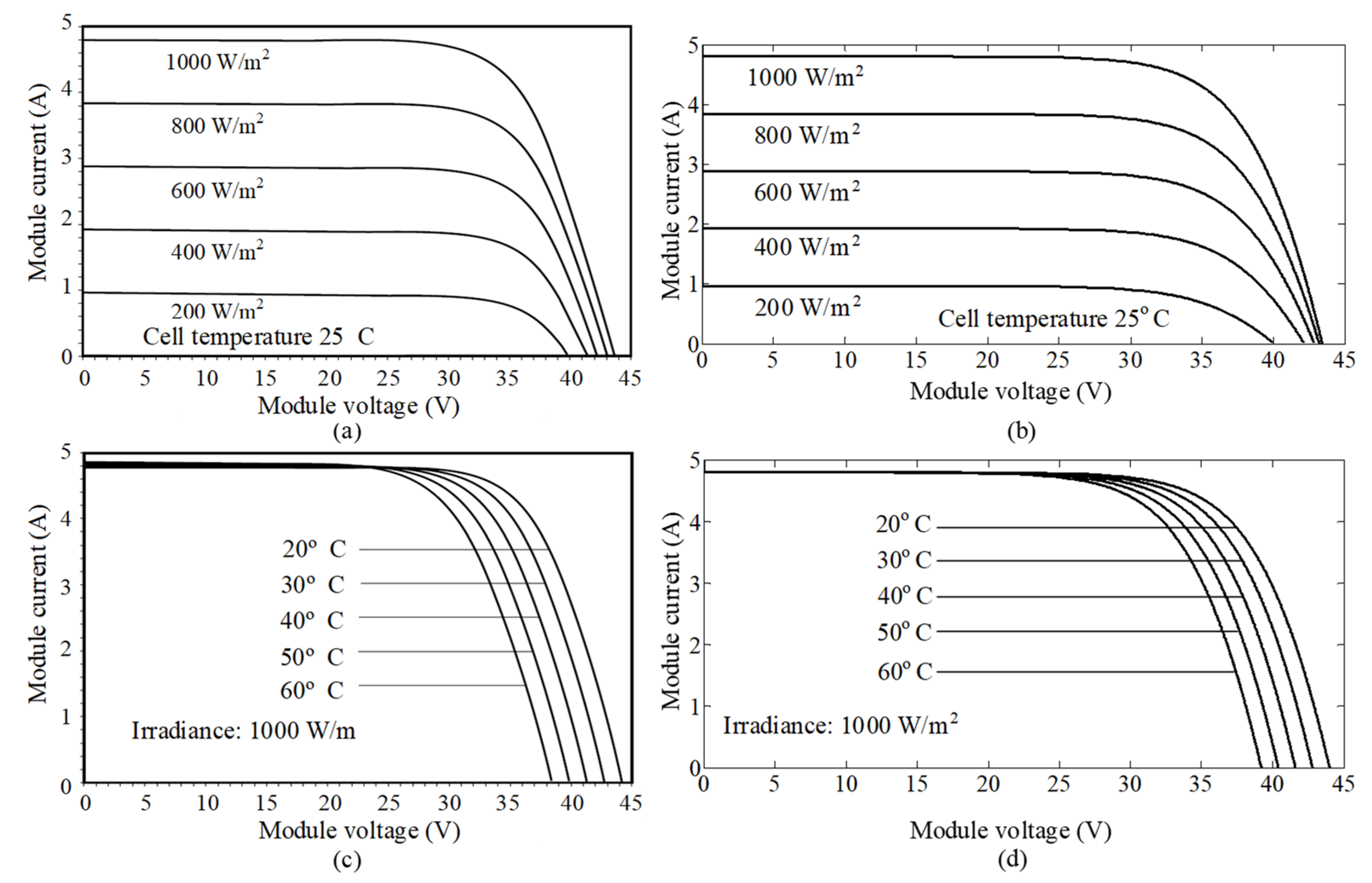
Manufacturers of PV modules provide the main parameters in their datasheet referred to reference values of irradiance (W) and temperature (T) at standard test conditions (STC), which corresponds to 1000 W/m2 and 25 °C and a family of curves that illustrates how the panel curves are modified when those values change. An example of the named main parameters is available in Table 1, which shows the main specifications of module Shell SP150 referred to STC.
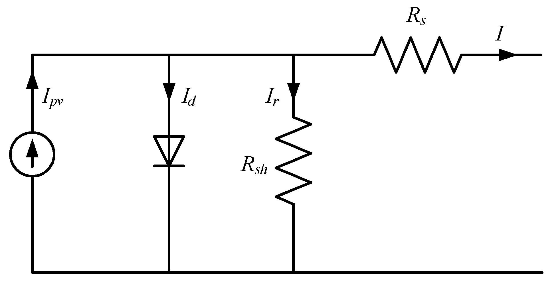
Most of the models in the literature assume the PV cell to be an electrical equivalent circuit (Figure 2). Those models require some parameters such as shunt resistance (Rsh), series resistance (Rs), the diode factor and the effective cell area. Nevertheless, they are not provided by the manufacturers in the datasheet, so this makes them complex to use.
Due to the aforementioned reasons, the mathematical model proposed in [21] is used in the NG study. Firstly, the PV current and voltage (I–V) curve in the STC is fitted and then the influence of irradiance and temperature is taken into account. The equations that describe the model are expressed as follows (1)–(5):
I p v = I S C , T W ( 1 B e ( V p v V O C , T W ) τ ( 1 B ) e ( V p v V O C , T W ) τ / 2 )
where I p v and V p v are the module current and voltage respectively. Short-circuit current at any irradiance and temperature conditions ( I S C , T W ) is determined as (2):
I S C , T W = I S C , S T C W W S T C .
In (2), I S C , S T C is the short-circuit current at STC, and W and W S T C are the current and the reference irradiance (1000 W/m2) respectively. Open-circuit voltage at any irradiance and temperature conditions (VOC,TW) are determined in (3):
V O C , T W = V O C , S T C k T ( T T S T C ) k W ( W W S T C ) / W
with V O C , S T C , T S T C , k T and k W as the open-circuit voltage at STC, the reference temperature (25 ºC) and the temperature and irradiance coefficient respectively. Constants B and τ can be calculated by the expressions (4) and (5), being V M P P and I M P P , the voltage and current values at the maximum power point (MPP) respectively:
B = 1 I M P P I S C e V M P P V O C τ
τ = V M P P I M P P ( I S C I M P P ) .
To validate the accuracy of the model, these equations are implemented in MATLAB/Simulink using as input parameters those in Table 1. Figure 3a,c represents the curves provided by the manufacturer and Figure 3b,d the simulated ones, respectively.

2.1.2. Battery and Supercapacitor Models

One of the most common ESS model aims to estimate the battery open-circuit voltage ( V B A T , O C ) as a function of the battery current ( I B A T ). The estimated voltage can control a voltage source in series with a resistance that models the instantaneous voltage drop due to the internal ESS resistance. V B A T , O C is obtained from (6) [22]:
V B A T , O C = V B A T 0 k Q Q I B A T d t + A e ( B I B A T d t )
where V B A T 0 is the battery voltage, K is the polarization voltage, Q is the battery capacity, I B A T d t represents the actual battery charge, A is the exponential zone amplitude and B the exponential zone time constant inverse.
In a similar way, it is possible to develop a generic model based on the supercapacitor parameters. Supercapacitor voltage ( V S C ) is estimated by the Stern Equation (7) [23]:
V S C = N S Q T d N p N e ε ε 0 A i + 2 N e N s R T F sinh 1 ( Q T N p N e 2 A i 8 R T ε ϵ 0 c ) R S C u i S C u .
N S , N p and N e represents the number of series and parallel supercapacitors, and the number of layers of electrodes respectively. Q T , d, ε , ε 0 , F, R and A i correspond to the electric charge, molecular radius, permittivity of the material, permittivity of free space, Faraday constant, ideal gas constant and the area between electrodes and electrolyte. Finally, R S C u and i S C u stand for the total resistance and the supercapacitor current.

3. Residential Nanogrid Energy Management System

According to Figure 1, the power flow is considered positive in the direction of the corresponding black arrows. Red arrows represent the possibility of each element of the system to operate in unidirectional or bidirectional way. From the same figure, the main power flow relationships are derived as:
P N E T = P L O A D P P V
P H E S S = P B A T + P S C  
P N G = P P V + P B A T + P S C  
where PNET represents the net power. PPV and PLOAD corresponds to the PV power and the power demanded by the household loads respectively. At the same time, PHESS, PBAT and PSC are the injected power by the HESS (total storage system, battery and supercapacitors). Finally, PNG is the power generated by the residential NG under study. Furthermore, the power demanded from the utility PGRID is positive when it injects power to the NG.

3.1. Hybrid Energy Storage System (HESS) Strategy and Constraints

Both battery and supercapacitor powers must be limited during their charging ( P B A T C and P S C C ) and discharging ( P B A T D and P S C D ) cycles to ensure their safety and life. In this sense, the following constrains have to be accomplished at any time ((11)–(14)):
P B A T D P B A T D m a x
P B A T C P B A T C m a x
P S C D P S C D m a x
P S C C P S C C m a x .
Just in case any of the previous variables overpass their maximum limits, the EMS will have to saturate the corresponding value, rearranging the energy surplus somehow. At the same time, the HESS has to operate within healthy SOC limits. Assuming that the initial SOC ( S O C 0 ) is known, the current SOC for the battery and supercapacitors can be estimated. The selected method for estimating the current battery SOC is based on the Coulomb counting method, which integrates the battery current flow over time. This method presents a simple implementation and just one measurement is required. In our particular case, the current flowing from the battery to the DC bus is considered positive and the current battery SOC ( S O C B A T ) is determined by Equation (15) [24]:
S O C B A T ( % ) = S O C 0 ( % ) 0 t i B A T ( t ) d t Q B A T 100
with iBAT (t) and QBAT as the battery current (A) and capacity (Ah), respectively. To determine the supercapacitor SOC (i.e., S O C S C ), the following expression is derived (16) [25]:
S O C S C ( % ) =   1 3 [ 4 ( V S C V S C N O M ) 2 1 ] 100 .
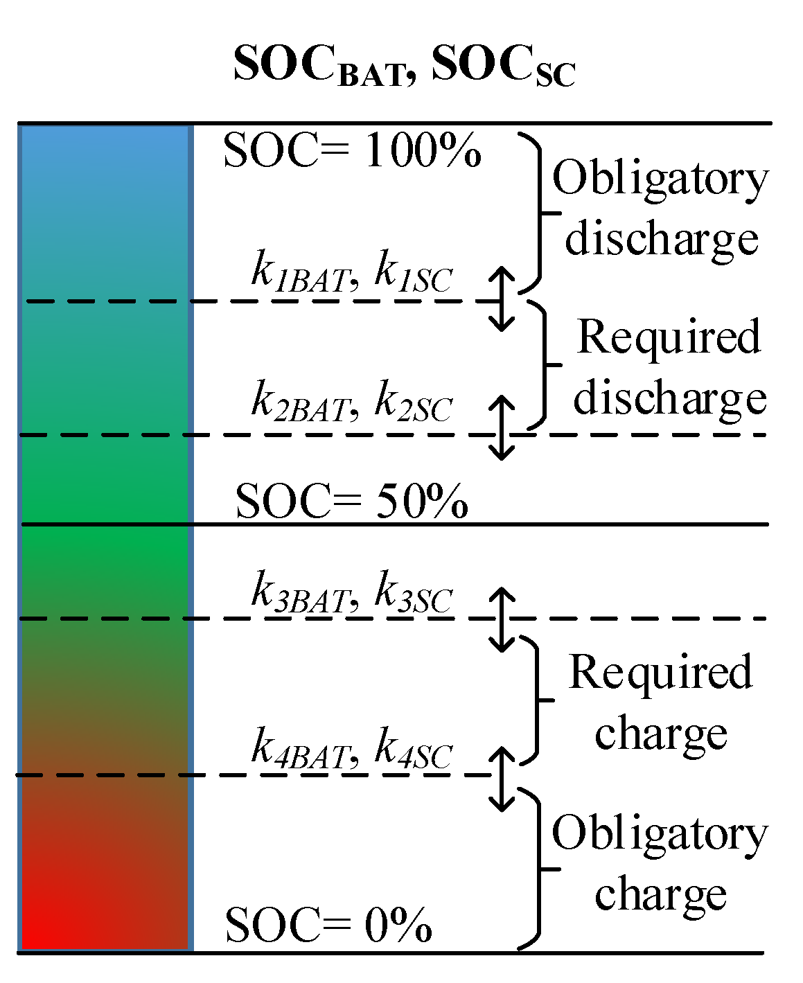
In (16), VSC and V S C N O M are the supercapacitor voltage and the supercapacitor nominal voltage. The HESS deals with several functionalities. For example, depending on the energy price, the HESS or the utility will release power when PNET > 0 if possible. The battery and the supercapacitors can also fulfill energy shifting by storing energy in some strategical times. For these kinds of purposes, the SOC is considered as a crucial issue. The ideal situation for any practical NG operation would be to keep the SOC around 50%. To further distinguish a multi-criteria based decision making, five SOC intervals are proposed. The SOC is divided by 4 user-customizable levels, k1, ..., k4, which can be different for the battery and for the supercapacitors. Figure 4 represents such different levels and the action to be taken (if possible).
As an example, if k4BAT < SOCBAT < k3BAT and PNET > 0, probably (depending on other factors) the utility will provide power to guarantee the load supply and to charge the battery. Another situation could be that 0 < SOCSC < k4SC and k2BAT < SOCBAT < k1BAT, and, depending on other factors to be detailed later, the battery will inject power to the supercapacitors.
In order to distribute the amount of PHESS that will be delivered or stored by the battery or by the supercapacitor, the following reasons are considered. Batteries are usually devoted to providing the bulk of energy in the long term, presenting a slow dynamic. Meanwhile, supercapacitors are suitable for providing or absorbing the power generation or demand peaks because of its fast response. In this sense, many previous works like [25,26] aim to distinguish between the low-frequency component and the high-frequency component of the power to be delivered/absorbed by the HESS. For this purpose, a conventional low-pass filter (LPF) will be used to extract the low-frequency component, which is LPF( P N E T ). Then, the power sharing will be as follows (17) and (18):
P B A T =   L P F ( P N E T ) P G R I D
P S C =   P N E T P B A T .

3.2. NG Net Power Trend

A quite interesting parameter to develop operation rules in the EMS for controlling the NG is the consideration of both the generation and consumption trend within the NG. The NG net power trend ( P N E T T ) can be understood as the predicted behavior of the net power. This parameter can help to improve the NG capability by storing or delivering power. In this sense, the NG can anticipate a future scenario with a more adequate HESS state. The P N E T T will help to smooth the power exchanged with the main grid and to improve the SOCBAT, besides contributing to increase the revenues for the NG users. It is important to note that this parameter will have only influence in the low-frequency component of PHESS, that is, in the battery power. Calculation of P N E T T is based on the derivative of PNET (19):
P N E T T = L P F   ( P N E T ( t ) ) L P F   ( P N E T ( t 1 ) ) T S
where TS is the sample rate (in the considered case of study is one hour).
A positive slope of PNET means that PPV is increased and/or PLOAD is decreased. Nevertheless, a negative slope is related to an increase in PPV generation and/or a reduction in PLOAD. At the same time, P N E T T values can be classified into several ranges: positive, slightly positive, zero, slightly negative or negative. Thresholds to determine this classification can be user-defined, depending on the power rating. In the NG under study, four thresholds are considered (τ1, τ2, τ3 and τ4) to define five ranges for P N E T T , as shown in Table 2.
An example of a possible rule in our expert system based on the consideration of P N E T T could be as follows. If τ4 < P N E T T < τ3 (slightly negative) and k2BAT < SOCBAT < k1BAT (obligatory discharge), and, depending on other factors to be detailed later, the battery will supply the load power instead of the main grid.

3.3. PV Power Regulation

The main goal of a PV system is usually the extraction of the maximum possible power from the panels, i.e., operation at the MPP is required. This operation corresponds to the maximum environmental benefits and renewable resources exploitation but, in certain situation, it could be required to apply power generation curtailment, changing from MPP operation mode to reference power point (RPP) operation mode. In this work, the operation at RPP will be taken as a secondary option due to the aforementioned reasons. At the same time, RPP can help to maintain SOCBAT and SOCSC within healthy limits (for example, if PLOAD is low and SOCBAT is high) or for providing ancillary services to the main grid (voltage and frequency regulation). There are several approaches to implement a RPP algorithm in the PV DC/DC power converter. This algorithm calculates the proper duty cycle for the power electronics switches to make the PV array working at any reference working point. In this paper, an algorithm based on the perturb and observe (P&O) method with adaptive step to minimize the power fluctuation is implemented. Details of this method are available in [27].
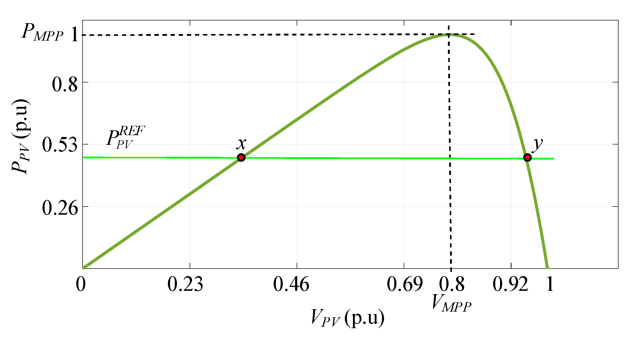
Figure 5 represents a typical P-V curve where the maximum power point with coordinates (VMPP, PMPP) is marked. The EMS will generate a reference power for the PV system ( P P V R E F ) depending on a specific situation. As can be seen, there are two feasible points that correspond with P P V R E F (x and y). The one placed at the right of the MPP will be the desired one for a better operation as VPV is higher (leading to a reduced duty cycle). For example, if during the NG operation PLOAD is low and SOCBAT is high, and at the same time the utility is not available, the EMS will determine the appropriate P P V R E F .

3.4. Energy Price

The NG under study can produce renewable energy for its own usage and sell excess to the main grid. Besides the aim of obtaining a friendly bi-directional operation between the NG and the utility, maximization of revenues is interesting to incentive the NG user in this business model, establishing negotiations with the utility or any aggregator [19]. At the same time, the HESS can store the energy surplus to be delivered during high-price time periods. In the case supposed in this paper, the EMS considers the same energy price for selling the energy by the NG to the utility and vice versa. At the same time, high-price and low-price periods are distinguished.

3.5. Comtrol Rules

The proposed EMS strategy consists of a set of rules to control the energy flow between the different components of the NG. The main objectives are the stability and the economy of the system. From the stability point of view, the power generation must satisfy the load demand at any time, and the AC system voltage and frequency must remain within the allowed range. From the economic point of view, the cost must be reduced as much as possible under the premise of guaranteeing system stability. The instructions at time t + 1 are computed using multi-objective optimization rules at time t. Taking into account the consideration mentioned in the previous sub-sections, the detailed rules are summarized in Table 3, Table 4 and Table 5. The NG is working in grid-connected mode and the PV is operating at MPP. Remind that P N E T T is not controllable as no demand response strategy is applied.
Table 3 shows the rules regarding charging/discharging the batteries and the injecting/extracting power into/from the utility grid, related to conditions about power production and load. The following acronyms are used for the power flows: B2L: Battery to load; B2G: Battery to Grid; G2B: Grid to Battery; N2G: Surplus to Grid; N2B: Surplus to Battery; G2L: Grid to Load. The inputs are SOCBAT and P N E T T . Each cell is divided into two or four sub-cells. The latter occupy the central part of the table. Within each cell, the sub-cells on the left represent the case of P N E T > 0 and those on the right P N E T < 0 . On the other hand, also within each cell, the top ones correspond to the case of high energy prices and the bottom ones to low energy prices. When a sub-cell contains two lines, it indicates that two actions are executed simultaneously, both with equal power flow. For the cells outside the central box, the SOC is in the limit zone and P N E T T presents a strong slope. In such a case, the priority will be to redirect the SOC to the central zone in order to assure the battery health. On the other hand, in the cells in the central box, attention will also be paid to the power purchase/sale price in order to get economic benefits. The reading of one of the cells is given below as an example (the one highlighted in yellow):
If ( k 3 B A T S O C B A T k 4 B A T -battery discharged) and ( τ 1 P N E T T τ 2 -trends is slightly positive ( m o r e   p o w e r   w i l l   b e   r e q u i r e d   f o r   P L O A D ) ) and ( P N E T > 0 -more power is required for PLOAD)) and (price is low) then the load will be supplied by the grid (50%, as the price is low) and by the battery (50%)(as we are not in the state of the battery “strongly discharged”).
Table 4 shows the rules regarding the regulation of the SOC in the supercapacitors. The following acronyms are used for the power flows: B2SC: Battery to Supercapacitor; G2SC: Grid to Supercapacitor. Inside each main cell, division in left and right corresponds to high-price and low-price time respectively.
Table 5 shows the rules regarding the regulation the operation mode in the PV system: MPPT: Maximum Power Point Tracking; RPPT: Reference Power Point Tracking. Inside each main cell, the division into left and right corresponds to P N E T > 0 and P N E T < 0 .

4. The Associated Rule-Based Expert System (RBES)

The NG described in this paper is a first step of a new development in the line of research of these authors. Therefore, the method and the representation of knowledge chosen is a frame designed to be reused in more complex (detailed) scenarios.
On the one hand, the experts summarize the electrical knowledge in tables, the conclusions of which have to be concatenated (in this first step that will take place only with Table 3, Table 4 and Table 5, but will be increased when further details are considered in future extensions of this work). The advantages of using rules when deductions have to be concatenated are well known.

4.1. Analysing the Structuring of the Information in the Tables

Let us use Table 3 to illustrate the procedure. This table is not homogeneous, as some cells have been merged.
Four variables are considered as input:
SOCBAT, PTNET, PNET, price
and 5 intervals are distinguished for the first and second variables and 2 possibilities for the third and fourth variables. In the expert system they will be abbreviated for the sake of simplicity:
  • SOCBAT:x1, x2, x3, x4, x5
  • PTNET: y1, y2, y3, y4, y5
  • PNET: z1, z2
  • Price: u1, u2
There are 6 possible conclusions (operations modes):
GRID2LOAD, GRID2BAT, NET2GRID, NET2BAT, BAT2LOAD, BAT2GRID.
In some cases (cells) there is one operation mode to be carried out, but in other cases there are two to be carried out.
In this case we would initially have a table with 52 × 22 cells = 100 cells. Nevertheless, the experts in electrical grids have grouped all cells outside the dark black rectangle in pairs (the third variable, z, is not considered for those cells), resulting in double height cells outside the dark black rectangle. One example is the upper left cell:
BAT2LOAD is recommended if we have x1 and y1 and u1 (despite having z1 or z2)
(these groupings are from an engineering origin: in many cases it does not matter whether we have z1 or z2: the same operation mode(s) is(are) recommended).
The table with abbreviated names of variables can be found in Table 6.

4.2. Combinatorial Manual Grouping of the Information in the Tables

For instance, the cell in the upper left corner of the table can be merged with the one below it. The same can be said about the two cells to their right.
There are many other possible groupings. Using colors can simplify viewing possible groupings (a task to be performed by a second group of experts: mathematicians or computer scientists, that have to consider which cells can be easily grouped into a single logic rule or into a few logic rules).
For instance, as exactly one yi must hold (because the intervals considered for PNETT are mutually exclusive), the information provided by all the cells containing GRID2BAT in the lower row of Table 6 (all columns but the last three ones) can be summarized as follows:
IF ×5 AND (NOT(y4 AND u2) OR NOT y5) THEN GRID2BAT
that is, “in the situation described by the last row (x5) and any of the possibilities for the columns yi (i∈{1,2,3,4,5}) except ((simultaneously y4 and u2) or y5) then GRID2BAT is operation mode is recommended”. If we use the usual logic symbols: (conjunction), (disjunction), ¬ (negation) and (implication), it can be written:
x 5     ( ¬ ( y 4     u 2 )     ¬ y 5 )     G R I D 2 B A T
Nevertheless, that would imply to include an integrity constraint describing that exactly one yi must hold. A preferable alternative equivalent way to express it (without the need to include integrity constraints) is:
x 5 ( y 1 y 2 y 3 ( y 4 u 1 ) ) G R I D 2 B A T
that is, “in the situation described by the last row (x5) and the columns (y1 or y2 or y3 or (y4 and u1)) then GRID2BAT operation mode is recommended”.
An advantage of the logic rule translation is that there are no problems if the groupings do not describe a partition of the set of cells but a covering, that is, if the subsets of cells are not disjointed two by two—that will only allow a conclusion (that is, the operation mode(s)) to be reached by forward firing more than one rule, which is not a problem.
For instance, an exact description of the information provided by the three cells containing GRID2BAT in the antepenultimate and penultimate rows and the first and second columns of the table is:
( ( x 3 x 4 ) y 1 u 1 ) ( x 4 y 1 u 2 ) G R I D 2 B A T
which is equivalent to the two simpler rules:
( x 3 x 4 ) y 1 u 1 G R I D 2 B A T
x 4 y 1 G R I D 2 B A T
The latter rules describing two intersecting (non-disjoint) subsets of cells (these will be the rules R2 and R3 of our RBES). Note that this is a technique typically used in Karnaugh maps.

5. About the Inference Engine Chosen

We have decided to use the algebraic inference engine described in detail in [28,29]. Among the many available existing approaches, we have chosen this one because of our experience with it and because of the possibility to straightforwardly move to a multivalued modal logic in future extensions, if necessary.

5.1. A Brief Overview of the Algebraic Model for Logic

Let us consider the Boolean logic case. If there are m propositional variables, X1,X2,…,Xm, the algebraic model considers the polynomial variables x1,x2,…,xm and the residue-class ring
Z2[x1,x2,…,xm]/<x12x1,x22x2,…,xm2xm>
where I = <x12 − x1,x22 − x2,…,xm2 − xm> denotes the ideal generated by x12 − x1,x22 − x2,…,xm2 − xm. If X Y X Y , X   x o r   Y and ¬ X are translated by x·y, x + y − x·y, x·y and 1−x, respectively, we have a ring isomorphism (or a Boolean algebra isomorphism, depending on the logic and algebraic operations considered).
The advantage of moving to the algebraic model is that we have an effective method for performing computations: Gröbner bases (and the derived normal form of a polynomial modulo an ideal) [30,31].
The main result is that Q is a tautological consequence of P (P→Q) is equivalent in the algebraic model to NormalForm(1 − q,<1 − p> + I) = 0, where p and q are the translations of P and Q in the polynomial model, respectively (and let us recall that 1−p and 1−q are the translations of ¬ P and ¬ Q in the polynomial model, respectively).
In the n-valued modal logic case (n prime) the only differences are:
  • Zn is considered instead of Z2 as the base field,
  • the ideal <x12x1,x22x2,…,xm2xm> is substituted by ideal <x1nx1,x2nx2,…,xmnxm>
so the polynomial ring considered is Zn[x1,x2,…,xm]/ <x1n − x1,x2n − x2,…,xmn − xm>, and:
  • the polynomial translations of the logic connectives do change.

5.2. A Brief Overview of the Algebraic Model for RBES (Boolean Case)

The facts, rules and integrity constraints are logic formulae stated as true. The rules and integrity constraints are fixed, meanwhile the set of facts stated as true change (although it must be a subset of the set of potential facts). The corresponding polynomial model presented in the previous subsection was Z2[x1,x2,…,xm]/<x12 − x1,x22 − x2,…,xm2 − xm> = Z2[x1,x2,…,xm]/I.
As the facts, rules and integrity constraints are stated as true, if
  • J is the polynomial ideal generated by the polynomial translation of the negation of the rules and integrity constraints, and
  • K is the polynomial ideal generated by the polynomial translation of the negation of the given facts,
Then its polynomial model is the residue-class ring:
(Z2[x1,x2,…,xm]/I)/(J + K)= Z2[x1,x2,…,xm]/(I + J + K).

5.3. The Maple Implementation of the Algebraic Model for RBES

The algebraic model for RBES can be easily implemented in any computer algebra system (CAS). For instance, in the CAS Maple, the implementation is straightforward. Firstly the packages Groebner and Ore_algebra (that allow to define the polynomial ring where the computations will take place) have to be loaded.
Afterwards the polynomial variables have to be declared. For instance, in the case of Table 6, we can store the x, z, y, u variables and the conclusions (operation modes) GRID2LOAD, GRID2BAT, etc. in a sequence (denoted, for instance, SV).
Then the polynomial ring where computations have to take place and the ordering to be applied and the order between variables have to be declared, and the polynomial ideal I has to be defined. At this point we are ready to define the polynomial translation of the logic connectives as Maple functions, which is straightforward and needs just 6 lines of code (the complete code required can be found in Appendix A in order the acquainted reader to be able to reproduce the computations).
For instance, the expression mentioned above:
( x 3 x 4 ) y 1 u 1 G R I D 2 B A T
is translated into Rule 2 of the RBES just by typing:
R2: = (x3 &OR x4) &AND y1 &AND u1 &IMP GRID2BAT:
which is very close to the usual notation in logic.

6. The Energy Management Nanogrid RBES Developed

The RBES developed will be described afterwards. It has been divided into 3 subsystems, each one dealing with the knowledge contained in one of the Table 3, Table 4 and Table 5.

6.1. Subsystem I

We have written 35 rules, similar to R2 in Section 5.3, that translate the knowledge contained in Table 6 (let as recall that this table is Table 3 with another notation). This translation can be made in several ways. The set (or list) of the negations of the chosen rules is a base of ideal J. Then we are ready to extract knowledge: if K is the ideal generated by the negation of the facts stated as true, the following two lines:
> B:=Basis([op(iI),op(J),op(K)], Orde);
> NormalForm(NEG(NET2BAT),B,Orde);
determine if NET2BAT can be deduced from the facts stated as true, by forward firing the 35 rules. The complete code of this subsystem can be found in Appendix B.
Nevertheless, it is usually more convenient to directly determine which of the possible operation modes (GRID2LOAD, GRID2BAT,…, BAT2GRID) are recommended. A brief procedure, that we have denoted operation_mode, allows us to do this with a single order (see Appendix C for details).
Moreover, obtaining the operation modes is not restricted to a single cell. Other more complex tasks can be solved by the RBES (see Appendix C).
Finally, we could underline that it is possible to check that the rules developed correctly translate the knowledge summarized in Table 6 using a procedure developed ad hoc (see Appendix D).

6.2. Subsystem II

The variables considered in the five rows of Table 4 were denoted x1, ...,x5 in Table 6. The variables in the upper part of Table 4 (SOCSC) are new, and are denoted v1, ...,v5, respectively. Each column is divided into two columns, corresponding variables of which (high-price, low-price), were denoted z1 and z2, respectively, in Table 6.
In this case we have written 4 rules that translate the knowledge contained in Table 4. For instance, the first rule, R101, is:
( x 1 x 2 ) ( v 4 v 5 ) B A T 2 S C
The corresponding code and the way knowledge extraction is performed is similar to Subsystem I (see Appendix E).

6.3. Subsystem III

The variables considered in the five rows of Table 5 were denoted x1, ...,x5 in Table 6. Similarly, the variables in the upper part of Table 5 were denoted y1, ...,y5 in Table 6. Each column is divided into two columns, corresponding variables of which (PNET positive or negative) will be denoted w1, w2, respectively.
In this case we have written 7 rules that translate the knowledge contained in Table 5. For instance, the first rule, R201, is:
( x 1 x 2 x 3 ) ( y 1 y 2 ) w 1 M P P T
The corresponding code and the way knowledge extraction is performed is similar to Subsystem I (see Appendix F).

7. Simulations

The associated RBES acting as EMS to the NG under study which was defined in Section 2 is tested through simulation using MATLAB/Simulink. Figure 6a shows an hourly PV generation and load consumption profiles for the NG under study. These curves are considered quite realistic for a 4 kW peak power PV generation system during a sunny day. PNET is represented in Figure 6b. Positive and negative values of PNET take place along the day. Thus, surplus or deficit must be compensated by the HESS or by the main grid. For simplicity, supposing that the main grid cannot participate (PGRID = 0), PBAT is represented in Figure 6c. It corresponds to the filtered value of PNET. Meanwhile, the supercapacitors will compensate the peak power according to Equation (18) as depicted in Figure 6d. Subsequently, Figure 7a depicts PNET and its slope is produced by two hourly consecutive samples. These slopes can be positive or negative. At the same time, P N E T T is displayed in Figure 7b.
From PNET, just the sign (positive or negative) of this value is required as RBES input. The value of P N E T T is given a consideration according to Table 2. For our case of study, thresholds equal to 1.5 kW, 0.5 kW, −0.5 kW and −1.5 kW are selected as constants τ1, τ2, τ3 and τ4 respectively. Current values of the SOCBAT and SOCSC, calculated with Equations (15) and (16), define specific intervals according to Figure 4. These intervals will also feed the RBES back (the facts stated as true at each moment). Regarding the SOC for both the battery and the supercapacitor, the following levels: 80%, 65%, 35% and 20%, were chosen for k1, k2, k3 and k4.
Considering as initial SOCBAT equal to 50% and initial SOCSC equal to 35%, the control of the NG with the proposed EMS and its associated RBES, clearly improves the performance of the HESS. Figure 8 represents the corresponding SOC before (SOCBAT and SOCSC) and after considering the proposed control (SOC´BAT and SOC´SC). Before the EMS activation, SOCBAT reaches almost 100% (around 20:00 p.m.) and falls 10% (around 10 a.m.). The maximum SOCSC corresponds to 14:30 p.m., with around 65%. On the other hand, at 7:30 a.m. the SOCSC is around 5%. As we can see in Figure 8, after applying the proposed control, both SOC are maintained close to 50% during the day. Thus, both SOC are kept within secure thresholds, guarantying a safety operation of the HESS.
Finally, battery and supercapacitor powers before and after (BAT and SC respectively) the EMS activation are represented in Figure 9a,b. Thanks to the EMS the system has a smoother response which also helps to improve the HESS lifespan.

8. Conclusions

This paper exposes the relevance of the EMS in the NG operation. A new approach to EMS for a NG was developed by designing a RBES step by step. The proposed approach has as its main advantage the reduction of the computational burden, while providing the possibility to straightforwardly move to a multivalued modal logic if the NG becomes more complex. At the same time, the possibility to concatenate the conclusions according to new variables or operation modes allows a modular design of the EMS. Further work will consider the presence of other energy sources in the NG, such as diesel generation, as well as the integration of some demand-side and peak load-shifting strategies. At the same time, environmental concerns are planned to be added in further extensions, as well as other energy required in the residential sector as thermal energy.
Regarding the chosen computational approach (a RBES), it has been shown how the knowledge included in table format can be conveniently condensed in the format of logic rules. The chosen inference engine (algebraic) is slower than other approaches already used by the authors, like answer set programming [32,33], but timings are very small, due to the size of problems treated (see Appendix B). The main advantage of the inference engine chosen is its simplicity (see Appendix A) and the fact that, during the development step, the underlying logic can be easily changed to a modal logic if desired (which is very convenient as this work is a first step in a new line of research by the authors).

Author Contributions

Conceptualization, C.R.-C. and E.R.-L.; methodology, C.R.-C. and E.R.-L.; validation, C.R.-C. and E.R.-L.; formal analysis, F.B.-G.; investigation, C.R.-C., E.R.-L. and F.B.-G.; writing—original draft preparation, C.R.-C. and E.R.-L.; writing—review and editing, E.R.-L. and F.B.-G.; supervision, C.R.-C., E.R.-L. and F.B.-G.; project administration, F.B.-G.; funding acquisition, C.R.-C., F.B.-G. and E.R.-L. All authors have read and agree to the published version of the manuscript.

Funding

This research was funded by the Junta de Extremadura within the programs “Ayudas Talento” (TA18003) and “Funding for Research Groups” (GR18087) and partially funded by the research project PGC2018-096509-B-100 (Government of Spain).

Institutional Review Board Statement

Not applicable.

Informed Consent Statement

Not applicable.

Data Availability Statement

Not applicable.

Acknowledgments

The authors would like to thank the anonymous reviewers for their most valuable comments and suggestions, that have greatly improved the final version of the article.

Conflicts of Interest

The authors declare no conflict of interest.

Appendix A

The Code of the Implementation Described in Section 5.3. The complete Maple code can be found afterwards. Note that the “&” symbols are necessary in Maple to declare infix operators.
> with(Groebner):
> with(Ore_algebra):
>SV:=x1,x2,x3,x4,x5,z1,z2,y1,y2,y3,y4,y5,u1,u2,GRID2LOAD,
> GRID2BAT, NET2GRID, NET2BAT, BAT2LOAD, BAT2GRID:
> A:=poly_algebra(SV,characteristic=2):
> Orde:=MonomialOrder(A,’plex’(SV)):
> fu:=var->var^2-var:
> iI:=map(fu,[SV]):
>  NEG  :=(m::algebraic) -> NormalForm(1+‘m‘,iI,Orde):
> ‘&AND’ :=(m::algebraic,n::algebraic) ->
>    NormalForm(expand(m*n),iI,Orde):
> ‘&OR’ :=(m::algebraic,n::algebraic) ->
>    NormalForm(expand(m+n+m*n),iI,Orde):
> ‘&IMP’ :=(m::algebraic,n::algebraic) ->
>    NormalForm(expand(1+m+m*n),iI,Orde):
> ‘&XOR’ :=(m::algebraic,n::algebraic) ->
>    (m &OR n) &AND NEG(m &AND n):
(observe that ideal I is denoted iI in the implementation above because I is a reserved word in Maple).
That is all the code required.

Appendix B. Subsystem I—Construction and Extracting Knowledge

The 35 rules that we have written to translate the knowledge contained in Table 6 are:
> R1 := x5 &AND (y1 &OR y2 &OR y3 &OR (y4 &AND u1)) &IMP GRID2BAT:
> R2 := (x3 &OR x4) &AND y1 &AND u1 &IMP GRID2BAT:
> R3 := x4 &AND y1 &IMP GRID2BAT:
> R4 := x5 &AND (y2 &OR y3 &OR y4) &AND u1 &IMP GRID2LOAD:
> R5 := (x3 &OR x4 &OR x5) &AND y1 &AND u1 &IMP GRID2LOAD:
> R6 := (x3 &OR x4) &AND (y2 &OR y3) &AND u1 &AND z2 &IMP GRID2LOAD:
> R7 := (x4 &OR x5) &AND y5 &AND u1 &IMP GRID2LOAD:
> R8 := x3 &AND y1 &AND u2 &IMP NET2BAT:
> R9 := x4 &AND y1 &AND u2 &IMP NET2BAT:
> R10:= x5 &AND (y1 &OR y2 &OR y3 &OR y4 &OR y5) &AND u2 &IMP NET2BAT:
> R11:= x3 &AND z2 &AND y2 &AND u2 &IMP NET2BAT:
> R12:= x4 &AND z1 &AND y3 &AND u2 &IMP NET2BAT:
> R13:= x4 &AND z2 &AND (y2 &OR y3) &AND u2 &IMP NET2BAT:
> R14:= (x1 &OR x2) &AND y1 &AND u1 &IMP BAT2LOAD:
> R15:= x1 &AND (y2 &OR y3 &OR y4 &OR y5) &AND u1 &IMP BAT2LOAD:
> R16:= (x2 &OR x3) &AND y5 &AND u1 &IMP BAT2LOAD:
> R17:= (x2 &OR x4) &AND (y2 &OR y3 &OR y4) &AND u1 &IMP BAT2LOAD:
> R18:= x3 &AND (y2 &OR y3 &OR y4) &AND z1 &AND u1 &IMP BAT2LOAD:
> R19:= x3 &AND (y2 &OR y4) &AND z2 &AND u1 &IMP BAT2LOAD:
> R20:= x1 &AND y2 &AND u2 &IMP BAT2GRID:
> R21:= x1 &AND (y3 &OR y4 &OR y5) &IMP BAT2GRID:
> R22:= x2 &AND z1 &AND (y2 &OR y3 &OR y4) &IMP BAT2GRID:
> R23:= x2 &AND z2 &AND y4 &IMP BAT2GRID:
> R24:= x3 &AND z1 &AND (y2 &OR y3 &OR y4) &AND u2 &IMP BAT2GRID:
> R25:= x3 &AND z1 &AND y4 &AND u1 &IMP BAT2GRID:
> R26:= x4 &AND z1 &AND y4 &IMP BAT2GRID:
> R27:= x2 &AND y5 &IMP BAT2GRID:
> R28:= x3 &AND y5 &AND u2 &IMP BAT2GRID:
> R29:= x1 &AND (y1 &OR y2 &OR y3 &OR y4 &OR y5) &AND u2 &IMP NET2GRID:
> R30:= x2 &AND y1 &AND u2 &IMP NET2GRID:
> R31:= (x2 &OR x3 &OR x4) &AND y5 &AND u2 &IMP NET2GRID:
> R32:= (x2 &OR x3 &OR x4) &AND (y2 &OR y3 &OR y4) &AND z1 &AND u2
    &IMP NET2GRID:
> R33:= x2 &AND (y2 &OR y3 &OR y4) &AND z2 &AND u2 &IMP NET2GRID:
> R34:= x3 &AND (y3 &OR y4) &AND z2 &AND u2 &IMP NET2GRID:
> R35:= x4 &AND y4 &AND z2 &AND u2 &IMP NET2GRID:
and the set (or list) of their negations is a base of ideal J:
J:=[NEG(R1),NEG(R2),NEG(R3),NEG(R4),NEG(R5),NEG(R6),NEG(R7),
 NEG(R8),NEG(R9),NEG(R10),NEG(R11),NEG(R12),NEG(R13),NEG(R14),
 NEG(R15),NEG(R16),NEG(R17),NEG(R18),NEG(R19),NEG(R20),
 NEG(R21),NEG(R22),NEG(R23),NEG(R24),NEG(R25),NEG(R26),
 NEG(R27),NEG(R28),NEG(R29),NEG(R30),NEG(R31),NEG(R32),
 NEG(R33),NEG(R34),NEG(R35) ]:
Now we are ready to extract knowledge. For instance, let us state as facts x2, z2, y2 and u1:
K:=[NEG(x2),NEG(z2),NEG(y2),NEG(u1)]:
Which of NET2BAT, BAT2GRID, BAT2LOAD, GRID2BAT, GRID2LOAD, NET2GRID follow from these facts? (the ideal considered is iI+J+K and its basis, B, is computed firstly):
> B:=Basis([op(iI),op(J),op(K)], Orde);
> NormalForm(NEG(NET2BAT),B,Orde);
            NET2BAT + 1
> NormalForm(NEG(BAT2GRID),B,Orde);
            BAT2GRID + 1
> NormalForm(NEG(BAT2LOAD),B,Orde);
             0
> NormalForm(NEG(GRID2BAT),B,Orde);
            GRID2BAT + 1
> NormalForm(NEG(GRID2LOAD),B,Orde);
            GRID2LOAD + 1
> NormalForm(NEG(NET2GRID),B,Orde);
            NET2GRID + 1
(the 6 calculations above took 0.078 s on a standard computer with a 8 GB RAM). 0 is obtained only for BAT2LOAD, so that is the only operation mode recommended in this case.

Appendix C. Subystem I—Simplifying Knowledge Extraction

Obtaining the operation modes can be simplified declaring them and using a simple procedure that performs the six questions and looks for the results equal to zero:
> Operation_Modes:=[NET2GRID,NET2BAT,BAT2LOAD,BAT2GRID,GRID2LOAD,
         GRID2BAT]:
> operation_mode:=proc(facts::list)
>  local i,K,OM,B;
> OM:=[[];
> K:=map(NEG,facts);
> B:=Basis([op(iI),op(J),op(K)], Orde);
> for i in Operation_Modes do
>  if NormalForm(NEG(i),B,Orde)=0 then OM:=[op(OM),i] end if;
>  end do;
> OM;
>  end proc:
For example:
> Facts:=[x1,u1,y1,z2]:
> operation_mode(Facts);
            [BAT2LOAD]
> Facts:=[x4,z1,y3,u2]:
> operation_mode(Facts);
            [NET2GRID, NET2BAT]
> Facts:=[x4,z1,y3,u2]:
> operation_mode(Facts);
            [NET2GRID, NET2BAT]
As said above, other more complex tasks can be solved by the RBES. For instance: Can something be deduced from x1 u1 (z1 z2)? Let us ask the system:
> Facts:=[x1,y1 &OR y2 &OR y3 &OR y4 &OR y5,u1,z1 &OR z2]:
> operation_mode(Facts);
            [BAT2LOAD]
(if we have a look at the first row of the table, BAT2LOAD is obtained in the first three odd columns and BAT2LOAD or BAT2GRID is obtained in the rest of the odd columns).

Appendix D. Subsystem I—Checking the Correctness of the Rules

A simple procedure that generates the columns of Table 6 (with its peculiarities) can be easily implemented in Maple (in order to check the correctness of the rules):
> column:=proc(facts::list)
> local i,j;
>  for i to 5 do
>   if {op(facts)} intersect {y2,y3,y4}<>{} and i in {2,3,4}
>    then
>     for j to 2 do
>      print(x||i,z||j,op(1,facts),op(2,facts),
>       operation_mode([op(facts),x||i,z||j]));
>     end do;
>    else
>     print(x||i,op(1,facts),op(2,facts),
>       operation_mode([op(facts),x||i]));
>   end if;
>  end do;
> end proc:
We can then ask, for example, for the first and fourth columns of Table 6 (note that the number of rows has been automatically adjusted):
> column([y1,u1]);
            x1, y1, u1, [BAT2LOAD]
            x2, y1, u1, [BAT2LOAD]
            x3, y1, u1, [GRID2LOAD, GRID2BAT]
            x4, y1, u1, [GRID2LOAD, GRID2BAT]
            x5, y1, u1, [GRID2LOAD, GRID2BAT]
> column([y2,u2]);
            x1, y2, u2, [NET2GRID, BAT2GRID]
           x2, z1, y2, u2, [NET2GRID, BAT2GRID]
           x2, z2, y2, u2, [NET2GRID]
           x3, z1, y2, u2, [NET2GRID, BAT2GRID]
           x3, z2, y2, u2, [NET2BAT]
           x4, z1, y2, u2, [NET2GRID]
           x4, z2, y2, u2, [NET2BAT]
            x5, y2, u2, [NET2BAT, GRID2BAT]

Appendix E. Subsystem II—Extracting Knowledge

The four rules describing the knowledge contained in Table 4 considered are:
> R101:= (x1 &OR x2) &AND (v4 &OR v5) &IMP BAT2SC:
> R102:= x3 &AND (v4 &OR v5) &AND z1 &IMP BAT2SC:
> R103:= x3 &AND (v4 &OR v5) &AND z2 &IMP GRID2SC:
> R104:= (x4 &OR x5) &AND (v4 &OR v5) &IMP GRID2SC:
and, in this case, the ideal J is:
> J:=[NEG(R101),NEG(R102),NEG(R103),NEG(R104)]:
We have, for example:
> Facts:=[x2,v4,z2]:
> operation_mode(Facts);
            [BAT2SC]
> Facts:=[x4,v4,z1 &OR z2]:
> operation_mode(Facts);
            [GRID2SC]

Appendix F. Subsystem III—Extracting Knowledge

The seven rules describing the knowledge contained in Table 5 are:
> R201:= (x1 &OR x2 &OR x3) &AND (y1 &OR y2) &AND w1 &IMP MPPT:
> R202:= x3 &AND (y1 &OR y2) &AND w1 &IMP MPPT:
> R203:= x3 &AND y1 &AND w2 &IMP MPPT:
> R204:= x4 &OR x5 &IMP MPPT:
> R205:= (x1 &OR x2) &AND y1 &AND w2 &IMP RPPT:
> R206:= (x1 &OR x2 &OR x3) &AND (y1 &OR y2) &AND w2 &IMP RPPT:
> R207:= (x1 &OR x2 &OR x3) &AND (y3 &OR y4 &OR y5) &IMP RPPT:
and, in this case, the ideal J is:
> J:=[NEG(R201),NEG(R202),NEG(R203),NEG(R204),NEG(R205),
 NEG(R206),NEG(R207)]:
For example:
> Facts:=[x3,y3,w1]:
> operation_mode(Facts);
            [RPPT]
> Facts:=[x4,y1 &OR y2 &OR y3 &OR y4 &OR y5, w1 &OR w2]:
> operation_mode(Facts);
            [MPPT]

Acronyms

ACAlternating Current
B2G, BAT2GRIDBattery to Grid
B2L, BAT2LOADBattery to Load
B2SC, BAT2SCBattery to Supercapacitor
CASComputer Algebra System
DCDirect Current
DER Distributed Energy Resources
EMSEnergy Management System
ESS Energy Storage System
G2B, GRID2BATGrid to Battery
G2L, GRID2LOADGrid to Load
G2SC, GRID2SCGrid to Supercapacitor
GCGrid-Connected
HESSHybrid Energy Storage System
LPFLow-Pass Filter
MPPMaximum Power Point
MGMicrogrid
MPPTMaximum Power Point Tracking
N2B, NET2BATSurplus to Battery
N2G, NET2GRIDSurplus to Grid
NGNanogrid
P&OPerturb and Observe
PVPhotovoltaic
PCCPoint of Common Coupling
RBESRule Based Expert System
RPPReference Power Point
RESRenewable Energy Sources
RPPTReference Power Point Tracking
SAStand-Alone
STCStandard Test Conditions
SOCState of Charge
STSStatic Transfer Switch

References

  1. European Commission. 2030 Climate & Energy Framework; European Commission: Brussels, Belgium; Available online: https://ec.europa.eu/clima/policies/strategies/2030_en#tab-0-0 (accessed on 24 November 2020).
  2. SETIS. Smart Electricity Grids. Available online: https://setis.ec.europa.eu/relatedjrc-activities/jrc-setis-reports/smart-electricity-grids (accessed on 3 April 2019).
  3. Lee, S.; Jin, H.; Vecchietti, L.F.; Hong, J.; Har, D. Short-Term Predictive Power Management of PV-Powered Nanogrids. IEEE Access 2020, 8, 147839–147857. [Google Scholar] [CrossRef]
  4. Sandgani, M.R.; Sirouspour, S. Energy Management in a Network of Grid-Connected Microgrids/Nanogrids Using Compromise Programming. IEEE Trans. Smart Grid 2018, 9, 2180–2191. [Google Scholar] [CrossRef]
  5. Ban, M.; Shahidehpour, M.; Yu, J.; Li, Z. A Cyber-Physical Energy Management System for Optimal Sizing and Operation of Networked Nanogrids With Battery Swapping Stations. IEEE Trans. Sustain. Energy 2019, 10, 491–502. [Google Scholar] [CrossRef]
  6. Luo, F.; Ranzi, G.; Wang, S.; Dong, Z.Y. Hierarchical Energy Management System for Home Microgrids. IEEE Trans Smart Grid 2019, 10, 5536–5546. [Google Scholar] [CrossRef]
  7. Farzaneh, H.; Shokri, M.; Kebriaei, H.; Aminifar, F. Robust Energy Management of Residential Nanogrids via Decentralized Mean Field Control. IEEE Trans. Sustain. Energy 2020, 11, 1995–2002. [Google Scholar] [CrossRef]
  8. Salazar, A.; Berzoy, A.; Song, W.; Velni, J.M. Energy Management of Islanded Nanogrids Through Nonlinear Optimization Using Stochastic Dynamic Programming. IEEE Trans. Ind. Appl. 2020, 56, 2129–2137. [Google Scholar] [CrossRef]
  9. Lee, S.; Lee, J.; Jung, H.; Cho, J.; Hong, J.; Lee, S.; Har, D. Optimal power management for nanogrids based on technical information of electric appliances. Energy Build. 2019, 191, 174–186. [Google Scholar] [CrossRef]
  10. Youssef, T.A.; Hariri, M.E.; Elsayed, A.T.; Mohammed, O.A. A DDS-Based Energy Management Framework for Small Microgrid Operation and Control. IEEE Trans. Ind. Inform. 2018, 14, 958–968. [Google Scholar] [CrossRef]
  11. Roncero-Clemente, C.; Gonzalez-Romera, E.; Barrero-González, F.; Milanés-Montero, M.I.; Romero-Cadaval, E. Power-Flow-Based Secondary Control for Autonomous Droop-Controlled AC Nanogrids with Peer-to-Peer Energy Trading. IEEE Access 2021, 9, 22339–22350. [Google Scholar] [CrossRef]
  12. Young, B.; Ertugrul, N.; Chew, H.G. Overview of optimal energy management for nanogrids (end-users with renewables and storage). In Proceedings of the 2016 Australasian Universities Power Engineering Conference (AUPEC), Brisbane, Australia, 25–28 September 2016; pp. 1–6. [Google Scholar] [CrossRef]
  13. Bhosale, R.; Agarwal, V. Fuzzy Logic Control of the Ultracapacitor Interface for Enhanced Transient Response and Voltage Stability of a DC Microgrid. IEEE Trans. Ind. Appl. 2019, 55, 712–720. [Google Scholar] [CrossRef]
  14. Barricarte, J.J.; Martín, I.S.; Sanchis, P.; Marroyo, L. Energy management strategies for grid integration of microgrids based on renewable energy sources. In Proceedings of the 10th International Conference on Sustainable Energy Technology, Istambul, Turkey, 4–7 September 2011; pp. 4–7. [Google Scholar]
  15. Arcos-Aviles, D.; Espinosa, N.; Guinjoan, F.; Marroyo, L.; Sanchis, P. Improved fuzzy controller design for battery energy management in a grid connected microgrid. In Proceedings of the IECON 40th IEEE Annu. IEEE Industrial Electronics Society, Dallas, TX, USA, 29 October 2014; pp. 2128–2133. [Google Scholar]
  16. Arcos-Aviles, D.; Pascual, J.; Marroyo, L.; Sanchis, P.; Guinjoan, F. Fuzzy Logic-Based Energy Management System Design for Residential Grid-Connected Microgrids. IEEE Trans. Smart Grid 2018, 9, 530–543. [Google Scholar] [CrossRef] [Green Version]
  17. Ding, Y.; Wang, Z.; Liu, S.; Wang, X. Energy Management Strategy of PV Grid-Connected Household Nano-Grid System. In Proceedings of the 2019 IEEE Power & Energy Society General Meeting (PESGM), Atlanta, GA, USA, 4–8 August 2019; pp. 1–5. [Google Scholar] [CrossRef]
  18. Ghiani, E.; Garau, M.; Celli, G.; Pilo, F.; Marongiu, G. Smart integration and aggregation of nanogrids: Benefits for users and DSO. In Proceedings of the 2017 IEEE Manchester PowerTech, Manchester, UK, 18–22 June 2017; pp. 1–6. [Google Scholar] [CrossRef]
  19. Latifi, M.; Rastegarnia, A.; Khalili, A.; Bazzi, W.M.; Sanei, S. A Self-Governed Online Energy Management and Trading for Smart Micro/Nano-Grids. IEEE Trans. Ind. Electron. 2020, 67, 7484–7498. [Google Scholar] [CrossRef] [Green Version]
  20. Caldognetto, T.; Mion, E.; Bruschetta, M.; Simmini, F.; Carli, R.; Tenti, P. A Model Predictive Approach for Energy Management in Smart Buildings. In Proceedings of the 2019 21st European Conference on Power Electronics and Applications (EPE ’19 ECCE Europe), Genova, Italy, 3–5 September 2019; pp. P.1–P.10. [Google Scholar] [CrossRef]
  21. Roncero-Clemente, C.; González-Romera, E.; Romero-Cadaval, E.; Milanés-Montero, M.I.; Miñambres-Marcos, V. PSCAD/EMTDC model for photovoltaic modules with MPPT based on manufacturer specifications. In Proceedings of the 2013 International Conference-Workshop Compatibility and Power Electronics, Ljubljana, Slovenia, 5–7 June 2013; pp. 69–74. [Google Scholar] [CrossRef]
  22. Tremblay, O.; Dessaint, L.; Dekkiche, A. A Generic Battery Model for the Dynamic Simulation of Hybrid Electric Vehicles. In Proceedings of the 2007 IEEE Vehicle Power and Propulsion Conference, Arlington, TX, USA, 9–12 September 2007; pp. 284–289. [Google Scholar] [CrossRef]
  23. Miniguano, H.; Barrado, A.; Fernández, C.; Zumel, P.; Lázaro, A. A General Parameter Identification Procedure Used for the Comparative Study of Supercapacitors Models. Energies 2019, 12, 1776. [Google Scholar] [CrossRef] [Green Version]
  24. Kong, S.N.; Chin-Sien, M.; Yi-Ping, C.; Yao-Ching, H. Enhanced coulomb counting method for estimating state-of-charge and state-of-health of lithium-ion batteries. Appl. Energy 2009, 86, 1506–1511. [Google Scholar] [CrossRef]
  25. Ruiz-Cortés, M.; Romero-Cadaval, E.; Roncero-Clemente, C.; Barrero-González, F.; González-Romera, E. Energy management strategy to coordinate batteries and ultracapacitors of a hybrid energy storage system in a residential prosumer installation. In Proceedings of the 2017 International Young Engineers Forum (YEF-ECE), Almada, Portugal, 5 May 2017; pp. 30–35. [Google Scholar] [CrossRef]
  26. Ruiz-Cortés, M.; Romero-Cadaval, E.; Roncero-Clemente, C.; Barrero-González, F.; González-Romera, E. Comprehensive study of the benefits of integrating a sharing energy strategy between prosumers. In Proceedings of the IECON 2017—43rd Annual Conference of the IEEE Industrial Electronics Society, Beijing, China, 29 October–1 November 2017; pp. 3609–3614. [Google Scholar] [CrossRef]
  27. Roncero-Clemente, C.; Vilhena, N.; Delgado-Gomes, V.; Romero-Cadaval, E.; Martins, J.F. Control and operation of a three-phase local energy router for prosumers in a smart community. IET Renew. Power Gener. 2020, 14, 560–570. [Google Scholar] [CrossRef] [Green Version]
  28. Roanes-Lozano, E.; Laita, L.M.; Roanes-Macías, E. A Groebner Bases Based Many-Valued Modal Logic Implementation in Maple. In AISC/Calculemus/MKM 2008, LNAI 5144; Autexier, S., Campbell, J., Rubio, J., Sorge, V., Suzuki, M., Wiedijk, F., Eds.; Springer: Berlin/Heidelberg, Germany, 2008; pp. 170–183. [Google Scholar] [CrossRef]
  29. Roanes-Lozano, E.; Laita, L.M.; Hernando, A.; Roanes-Macías, E. An algebraic approach to rule based expert systems. Rev. R. Acad. Cien. Ser. A. Mat. 2010, 104, 19–40. [Google Scholar] [CrossRef]
  30. Buchberger, B. Bruno Buchberger’s PhD Thesis 1965: An algorithm for finding the basis elements of the residue class ring of a zero dimensional polynomial ideal. J. Symb. Comp. 2006, 41, 3–4. [Google Scholar] [CrossRef] [Green Version]
  31. Cox, D.; Little, J.; O’Shea, D. Ideals, Varieties, and Algorithms; Springer: Berlin/Heidelberg, Germany, 1992. [Google Scholar]
  32. Smodels Web Page. Available online: http://www.tcs.hut.fi/Software/smodels/ (accessed on 14 February 2021).
  33. Roanes-Lozano, E.; Alonso, J.A.; Hernando, A. An approach from answer set programming to decision making in a railway interlocking system. RACSAM 2014, 108, 973–987. [Google Scholar] [CrossRef]
Figure 1. The residential nanogrid considered in the study.
Mathematics 09 00487 g001
Figure 2. Equivalent circuit of a photovoltaic (PV) cell.
Mathematics 09 00487 g002
Figure 3. Current and voltage (I–V) photovoltaic (PV) curves. (a) I–V characteristics provided by the manufacturer for different irradiance values; (b) I–V characteristics simulated for different irradiance values; (c) I–V characteristics provided by the manufacturer for different temperatures and (d) I–V characteristics simulated for different temperatures.
Mathematics 09 00487 g003
Figure 4. State of charge (SOC) intervals and corresponding energy management system (EMS) action.
Mathematics 09 00487 g004
Figure 5. Traditional P-V curve.
Mathematics 09 00487 g005
Figure 6. HESS power distribution. (a) PPV and PLOAD; (b) PNET; (c) PBAT and (d) PSC.
Mathematics 09 00487 g006
Figure 7. NG net power trend analysis. (a) PNET and the slopes coming from two consecutive samples (hourly) and (b) P N E T T .
Mathematics 09 00487 g007
Figure 8. Improved performance of the NG thanks to the RBES acting as EMS. (a) SOCBAT and SOC´BAT and (b) SOCSC and SOC´SC.
Mathematics 09 00487 g008
Figure 9. Smoother responses in the battery and supercapacitor powers thanks to the RBES acting as EMS. (a) PBAT and BAT and (b) PSC and SC.
Mathematics 09 00487 g009
Table 1. Electrical characteristics of Shell SP150-P module at standard test conditions (STC).
ParameterDescriptionValue
Pmpp (W)Power at maximum power point150
Vmpp (V)Voltage at maximum power point34
Voc (V)Open circuit voltage43.4
Isc (A)Short circuit current4.8
Table 2. Proposed ranges for P N E T T .
Interval   for   P N E T T Consideration
P N E T T τ 1 Power trend positive
τ 1 P N E T T τ 2 Power trend slightly positive
τ 2 P N E T T τ 3 Power trend null
τ 3 P N E T T τ 4 Power trend slightly negative
τ 4 P N E T T Power trend negative
Table 3. EMS control rules for charging/discharging the batteries.
St . 1 : P N E T T τ 1 St . 2 : τ 1 P N E T T τ 2 St . 3 : τ 2 P N E T T τ 3 St . 4 : τ 3 P N E T T τ 4 St . 5 : τ 4 P N E T T
St . 1 : 100 % S O C B A T k 1 B A T
(strongly charged)
B2LN2GB2LN2G
B2G
B2L
B2G
N2G
B2G
B2L
B2G
N2G
B2G
B2L
B2G
N2G
B2G
St . 2 : k 1 B A T S O C B A T k 2 B A T
(charged)
B2LN2GB2L
B2G
N2G
B2G
B2L
B2G
N2G
B2G
B2L
B2G
N2G
B2G
B2L
B2G
N2G
B2G
B2LN2GB2LN2GB2L
B2G
N2G
B2G
St . 3 : k 2 B A T S O C B A T k 3 B A T
(intermediated)
G2L
G2B
N2BB2LN2G
B2G
B2LN2G
B2G
B2L
B2G
N2G
B2G
B2LN2G
B2G
B2L
G2L
N2BG2LN2GB2LN2G
St . 4 : k 3 B A T S O C B A T k 4 B A T
(discharged)
G2L
G2B
N2B
G2B
B2LN2GB2LN2G
N2B
B2L
B2G
N2G
B2G
G2LN2G
B2L
G2L
N2BB2L
G2L
N2BB2LN2G
St . 5 : k 4 B A T S O C B A T 0 %
(strongly discharged)
G2L
G2B
N2B
G2B
G2L
G2B
N2B
G2B
G2L
G2B
N2B
G2B
G2L
G2B
N2BG2LN2B
Table 4. EMS control rules for supercapacitors.
St . 1 100 % S O C S C k 1 S C St . 2 k 1 S C S O C S C k 2 S C St . 3 k 2 S C S O C S C k 3 S C St . 4 k 3 S C S O C S C k 4 S C St . 5 k 4 S C S O C S C 0
St . 1 100 % S O C B A T k 1 B A T
(strongly charged)
------B2SCB2SCB2SCB2SC
St . 2 : k 1 B A T S O C B A T k 2 B A T
(charged)
-------B2SCB2SCB2SCB2SC
St . 3 : k 2 B A T S O C B A T k 3 B A T
(intermediated)
-- ---B2SCG2SCB2SCG2SC
St . 4 : k 3 B A T S O C B A T k 4 B A T
(discharged)
------G2SCG2SCG2SCG2SC
St . 5 : k 4 B A T S O C B A T 0 %
(strongly discharged)
------G2SCG2SCG2SCG2SC
Table 5. EMS control rules for the PV system.
St . 1 : P N E T T τ 1 St . 2 : τ 1 P N E T T τ 2 St . 3 : τ 2 P N E T T τ 3 St . 4 : τ 3 P N E T T τ 4 St . 5 : τ 4 P N E T T
St . 1 100 % S O C B A T k 1 B A T
(strongly charged)
MPPTRPPTMPPTRPPTRPPTRPPTRPPTRPPTRPPTRPPT
St . 2 : k 1 B A T S O C B A T k 2 B A T
(charged)
MPPTRPPTMPPTRPPTRPPTRPPTRPPTRPPTRPPTRPPT
St . 3 : k 2 B A T S O C B A T k 3 B A T
(intermediated)
MPPTMPPTMPPTRPPTRPPTRPPTRPPTRPPTRPPTRPPT
St . 4 : k 3 B A T S O C B A T k 4 B A T
(discharged)
MPPTMPPTMPPTMPPTMPPTMPPTMPPTMPPTMPPTMPPT
St . 5 : k 4 B A T S O C B A T 0 %
(strongly discharged)
MPPTMPPTMPPTMPPTMPPTMPPTMPPTMPPTMPPTMPPT
Table 6. Table 3 with the notation of the rule-based expert system (RBES).
TABLE NUMBER 6 y1y2y3y4y5
u1    u2u1    u2u1    u2u1    u2u1    u2
x1z1
-----
z2
BAT
2
LOAD
NET
2
GRID
BAT
2
LOAD
NET2GRID
BAT2GRID
BAT2LOAD
BAT2GRID
NET2GRID
BAT2GRID
BAT2LOAD
BAT2GRID
NET2GRID
BAT2GRID
BAT2LOAD
BAT2GRID
NET2GRID
BAT2GRID
x2z1
-----
z2
BAT
2
LOAD
NET
2
GRID
BAT2LOAD
BAT2GRID
NET2GRID
BAT2GRID
BAT2LOAD
BAT2GRID
NET2GRID
BAT2GRID
BAT2LOAD
BAT2GRID
NET2GRID
BAT2GRID
BAT2LOAD
BAT2GRID
NET2GRID
BAT2GRID
BAT2LOADNET2GRIDBAT2LOADNET2GRIDBAT2LOAD
BAT2GRID
NET2GRID
BAT2GRID
x3z1
-----
z2
GRID2LOAD
GRID2BAT
NET
2
BAT
BAT2LOADNET2GRID
BAT2GRID
BAT2LOADNET2GRID
BAT2GRID
BAT2LOAD
BAT2GRID
NET2GRID
BAT2GRID
BAT
2
LOAD
NET2GRID
BAT2GRID
BAT2LOAD
GRID2LOAD
NET2BATGRID2LOADNET2GRIDBAT2LOADNET2GRID
x4z1
------
z2
GRID2LOAD
GRID2BAT
NET2BAT
GRID2BAT
BAT2LOADNET2GRIDBAT2LOADNET2GRID
NET2BAT
BAT2LOAD
BAT2GRID
NET2GRID
BAT2GRID
GRID
2
LOAD
NET
2
GRID
BAT2LOAD
GRID2LOAD
NET2BATBAT2LOAD
GRID2LOAD
NET2BATBAT2LOADNET2GRID
x5z1
------
z2
GRID2LOAD
GRID2BAT
NET2BAT
GRID2BAT
GRID2LOAD
GRID2BAT
NET2BAT
GRID2BAT
GRID2LOAD
GRID2BAT
NET2BAT
GRID2BAT
GRID2LOAD
GRID2BAT
NET
2
BAT
GRID
2
LOAD
NET
2
BAT
Publisher’s Note: MDPI stays neutral with regard to jurisdictional claims in published maps and institutional affiliations.