Article

Meshing Drive Mechanism of Double Traveling Waves for Rotary Piezoelectric Motors

School of Mechanical and Electrical Engineering, Guangzhou University, Guangzhou 510006, China
*
Author to whom correspondence should be addressed.
Mathematics 2021, 9(4), 445; https://doi.org/10.3390/math9040445
Submission received: 7 January 2021 / Revised: 11 February 2021 / Accepted: 18 February 2021 / Published: 23 February 2021
(This article belongs to the Special Issue Finite Element Modeling in Computational Friction Contact Mechanics)

Abstract

:
Rotary piezoelectric motors based on converse piezoelectric effect are very competitive in the fields of precision driving and positioning. Miniaturization and larger output capability are the crucial design objectives, and the efforts on structural modification, new materials application and optimization of control systems are persistent but the effectiveness is limited. In this paper, the resonance rotor excited by stator is investigated and the meshing drive mechanism of double traveling waves is proposed. Based on the theoretical analysis of bending vibration, the finite element method (FEM) is used to compare the modal shape and modal response in the peripheric, axial, and radial directions for the stator and three rotors. By analyzing the phase offset and vibrational orientation of contact particles at the interface, the principle of meshing traveling waves is discussed graphically and the concise formula obtaining the output performance is summarized, which is analogous with the principles of gear connection. Verified by the prototype experimental results, the speed of the proposed motor is the sum of the velocity of the stator’s contact particle and the resonance rotor’s contact particle, while the torque is less than twice the motor using the reference rotor.

1. Introduction

Piezoelectric actuation is a key technology to achieve the function of precision drive and microfabrication. The converse piezoelectric effect is utilized to transform electrical energy into mechanical motion [1,2]. The linear piezoelectric actuator [3,4,5], rotary piezoelectric motor [6,7,8,9], micro-perfusion pump [10,11], piezoelectric functionally graded plates [12,13] and ultrasonic transducer [14,15,16,17] have been developed and applied in the fields of aerospace products, nontraditional machining, cell delivery, health monitoring and structural control. The piezoelectric actuators using novel materials and complex modes are nowadays investigated to further enhance the torque-weight ratio and working stability. Wu et al. designed the lightweight rotary piezoelectric motors using the polymer-based vibrator and studied the high-order vibration mode yielding a relatively high electromechanical coupling factor [18,19]. Cao et al. researched the dynamics of a polymer-based bimodal piezoelectric motor by using the Kelvin–Voigt viscoelastic model [20]. Shi et al. developed a self-adapting noncontact piezoelectric motor adopting a flexible structure to generate acoustic radiation force [21]. Yin et al. developed a single-mode linear ultrasonic motor with large output thrust and fast output velocity [22]. Nakamura et al. designed a limit error feedback controller to improve the stability of rotary piezoelectric motors at angular speed saturation [23]. Koc et al. proposed a frequency tracking method by using a microcontroller and a dual op-amp pair to handle the operating frequency drift of the multimode excitation type piezoelectric motor [24]. Mustafa et al. investigated the effect of preload on the driving characteristics and proposed the dynamic preload control as the supplementary controller to enhance performance [25,26]. Over the various piezoelectric actuators, the rotary piezoelectric motor is the most competitive and prospective in space exploration, focusing systems and microrobots because of its unique merits including nanometer positioning accuracy, fast response and self-latching and no electromagnetic interference [27,28,29,30]. Hagood et al. have modelled and predicted the general performance for traditional rotary piezoelectric motors utilizing the Rayleigh–Ritz assumed mode energy method [31]. The authors firstly took into account how the interface forces between the stator and rotor affect the amplitude of traveling wave within the stator. The work provided a general framework for modeling the rotary piezoelectric motors and a design tool for optimizing the motor’s geometries and materials.
To acquire the superior output performance, the efforts on structure design and drive control are not ceasing, aiming to increase the vibrational amplitude of contact particles and track the drive frequency of the stator [32,33,34,35]. Because of the friction-driven mechanism of rotary piezoelectric actuators [31,36,37,38], it is difficult to obtain a major improvement for the power and efficiency utilizing the traditional methods such as structural modification or algorithm optimization. The sandwich structure with two stators and one rotor is a simple assumption for acquiring the twice drive capability [39], which is verified theoretically and in a laboratory but the design is deviating from the advantage of miniaturization and higher power density. Bai et al. first studied the piezoelectric actuation with two traveling waves by electrifying the stator and rotor [40]. Dong et al. modified the structure of the double vibrators and found that the output power was enhanced obviously [41]. To prevent the power supply lines from knotting, an electric slip ring is essential for energizing the rotor. The complicated mechanical structure would lead to the unstable operation and limited application.
In this paper, energized by the vibration of stator, the traveling wave would be also generated at the rotor. The compact structure of the piezoelectric motor is maintained because of nonelectric excitation for the rotor. Assuming that two traveling waves could drive each other like the mesh transmission of matching gears, the drive mode of the novel rotary piezoelectric motor is named as the meshing drive of double traveling waves. The meshing mechanism or principle will be investigated by employing the resonance rotor, reference rotor and flexible rotor. As a highly efficient and reliable modern mathematical tool for structural design and multiphysics coupling analysis [42,43], the finite element method (FEM) is used to calculate the mode shapes and modal responses. According to the amplitude comparison and analysis of phase offset and vibrational orientations, the meshing principle of two traveling waves is discussed graphically and the formula of the speed and torque is concluded, with the verification of the prototype experiment.

2. Materials and Methods

2.1. Input Parameters and Boundary Conditions for FEM

The rotary piezoelectric motor is traditionally assembled with a stator and a rotor. To investigate the meshing principle at the contact interface of the piezoelectric motor, three rotors including a resonance rotor, reference rotor and flexible rotor are employed. All the stator and rotors can be called vibrators because of their syntonic characteristics. The stator consists of the metal substrate and the piezoelectric wafer. The resonance rotor has the same mechanical structure and material composition as the stator to ensure the undifferentiated eigenfrequency. The reference rotor is designed with different structure and same substrate material aimed to acquire the obvious frequency offset from the stator. The flexible rotor is fabricated with aluminum and with different structures with the stator, which is generally employed by the commercial ultrasonic motors. The material composition and main structural parameters are presented in Table 1.
Finite element analysis is performed to investigate and distinguish the mode shapes and modal responses of the stator and different rotors, using the commercial finite element software COMSOL Multiphysics. The mesh generation of finite element models is controlled automatically by piezoelectricity multiphysics of the software, setting with the “Fine” level of element size. Before the numerical calculation, the materials attribute and the boundary conditions are determined, with the input parameters, as shown in Table 2.
For the eigenfrequency calculation of the stator, the inner circular surface and bottom transverse plane of the inner ring are imposed by a fixed constraint, and the axial pre-compression force equaling to 200 N is exerted on the contact interface, that is, the top transverse plane of the contact teeth. The boundary constraints of three rotors are consistent but different with the stator. The inner circular surface is also fixed. The bottom transverse plane of the inner ring and the contact interface is pressured with 200 N.
In order to obtain the modal response of the vibrators, a zero-to-peak voltage of 150 V is exerted upon the piezoelectric wafer of the stator. The alternating force generated by the stator is applied on the contact interface of each rotor circumferentially.

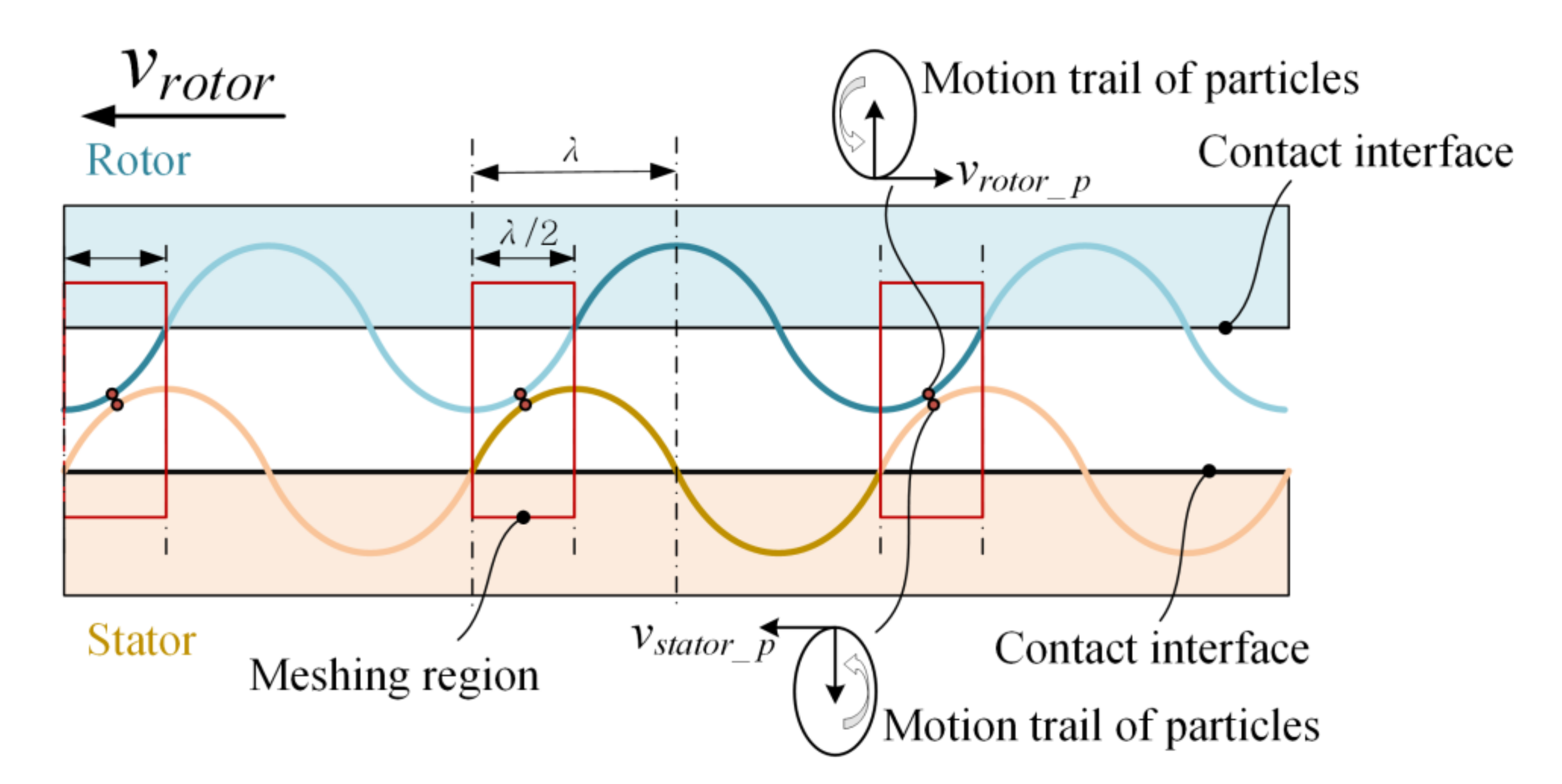
2.2. Theoretical Derivation for Wave Generating

To generate a traveling wave in the stator, the piezoelectric wafer is divided into two symmetrical zones denoting as A and B with the circumferential interval of λ / 4 and 3 λ / 4 , where λ is wave length [38]. Each zone is constituted of eight polarized subareas that have the opposite direction of polarization to the adjacent ones. Excited by the independent alternating voltage signals, two out-of-plane bending modes are generated at the stator and the mode shape functions are described as
ϕ A ( r , θ ) = R ( r ) sin n θ ϕ B ( r , θ ) = R ( r ) cos n θ
where R ( r ) is the radial distributed amplitude coefficient, n is the sinusoidal wave number generated at the stator, sin n θ is the displacement distribution function of mode A, cos n θ is the displacement distribution function of mode B. The modal responses are described as
w A ( r , θ , t ) = W A R ( r ) sin n θ cos ω n t = ϕ A ( r , θ ) q A ( t ) w B ( r , θ , t ) = W B R ( r ) cos n θ cos ( ω n t + φ ) = ϕ B ( r , θ ) q B ( t )
where W A is the response amplitude of mode A, W B is the response amplitude of mode B, φ is the phase difference of two modal responses, q A represents the modal coordinate of mode A, q B represents the modal coordinate of mode B.
q A = W A cos ω n t q B = W B cos ( ω n t + φ )
On the basis of the superposition principle, when the piezoelectric wafer is excited by two alternating voltage signals, the displacement response of the stator is constituted of a forward traveling wave expressed as sin ( n θ ω n t ) , inverted traveling wave as sin ( n θ + ω n t ) and standing wave as cos n θ cos ω n t , which is described as
w = w A + w B = 1 2 R ( r ) ( W A W B sin φ ) sin ( n θ + ω n t )       + ( W A + W B sin φ ) sin ( n θ ω n t ) + 2 W B cos φ cos n θ cos ω n t
If the phase difference is equaling to π / 2 or π / 2 and the response amplitudes of two standing waves are equivalent and expressed as W A = W B = W 0 , the component of standing waves is not included and the displacement response can be described as
w ( r , θ , t ) = W 0 R ( r ) sin ( n θ ω n t ) , φ = π 2 w ( r , θ , t ) = W 0 R ( r ) sin ( n θ + ω n t ) , φ = π 2
To obtain the accordant mode shape of resonance rotor, bending vibration analysis is performed by supposing the rotor as an equivalent simply supported beam model [44]. On the base of equilibrium equations of force and moment, the differential equation of bending vibration for uniform beam with homogeneous material is described as
2 x 2 E I 2 w x 2 + ρ S 2 w t 2 = 0
E I 4 w x 4 + ρ S 2 w t 2 = 0
where E represents the material elastic modulus, ρ represents the material density of equivalent beam, S represents the cross-sectional area of equivalent beam, I represents inertia moment of cross section to neutral axis. Based on separation of variables, the displacement function of natural vibration is described as
w ( x , t ) = ϕ ( x ) q ( t )
The oscillatory differential equation and the displacement response could be deduced as
E I d 4 ϕ ( x ) d x 4 q ( t ) + ρ S ϕ ( x ) d 2 q ( t ) d t 2 = 0
w ( x , t ) = i = 1 ϕ i ( x ) q i ( t ) = i = 1 ϕ i ( x ) ( A i sin ω i t + B i cos ω i t )
ϕ i ( x ) = F i sin β i x = F i sin i π l x
q i ( t ) = A i sin ω i t + B i cos ω i t
where A i and B i are determined by initial displacement and velocity of vibrational particles, ω i represents the resonance frequency, ϕ i ( x ) represents the mode shape function, q i ( t ) represents the modal coordinates.
Equation (10) presents that the displacement response of rotor particles is the linear combination of various natural modes of vibration. When the drive frequency of the motor is deviating from the resonance frequency, the modal response is the superposition of various natural modes of vibration.

3. Results and Discussion

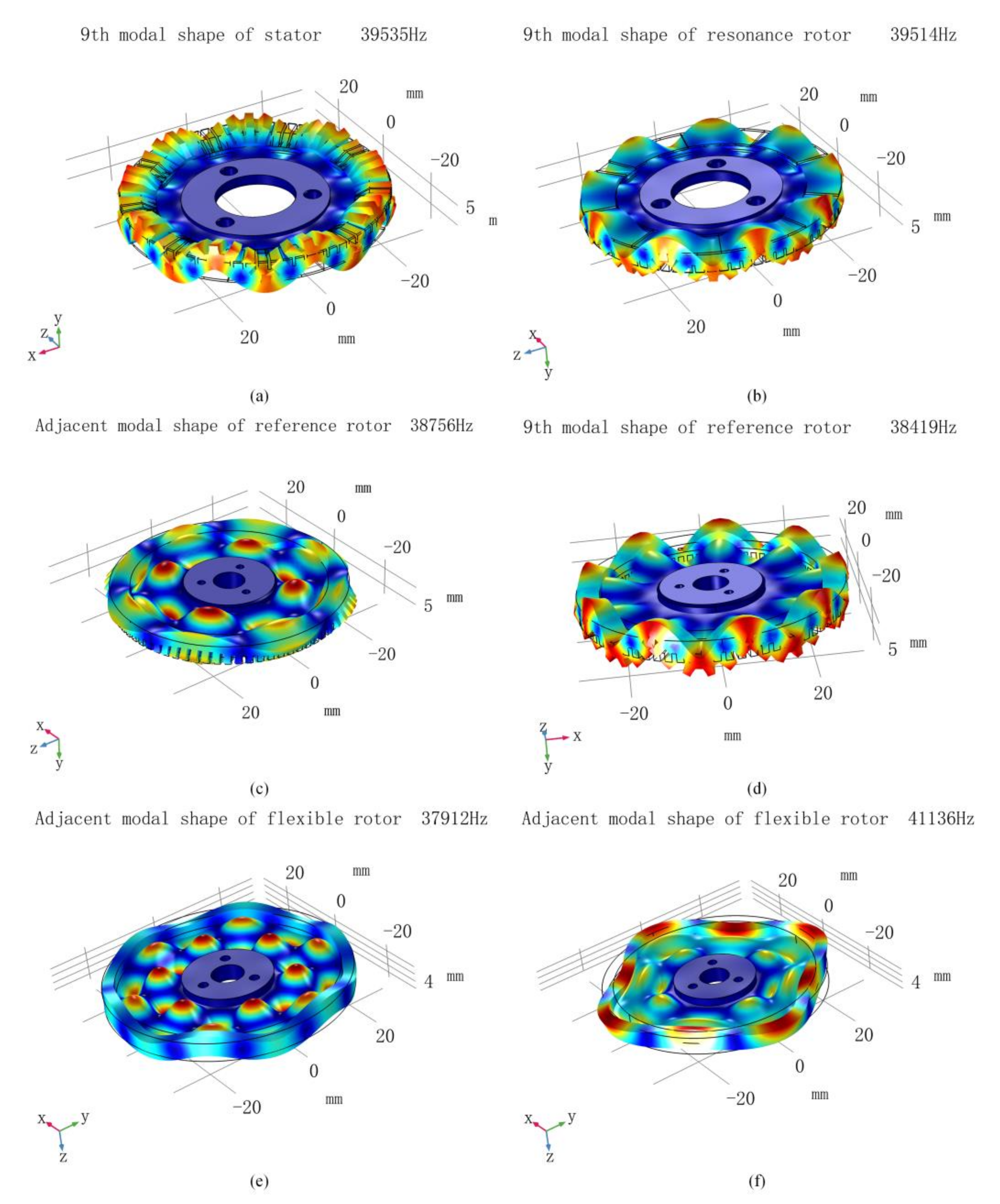
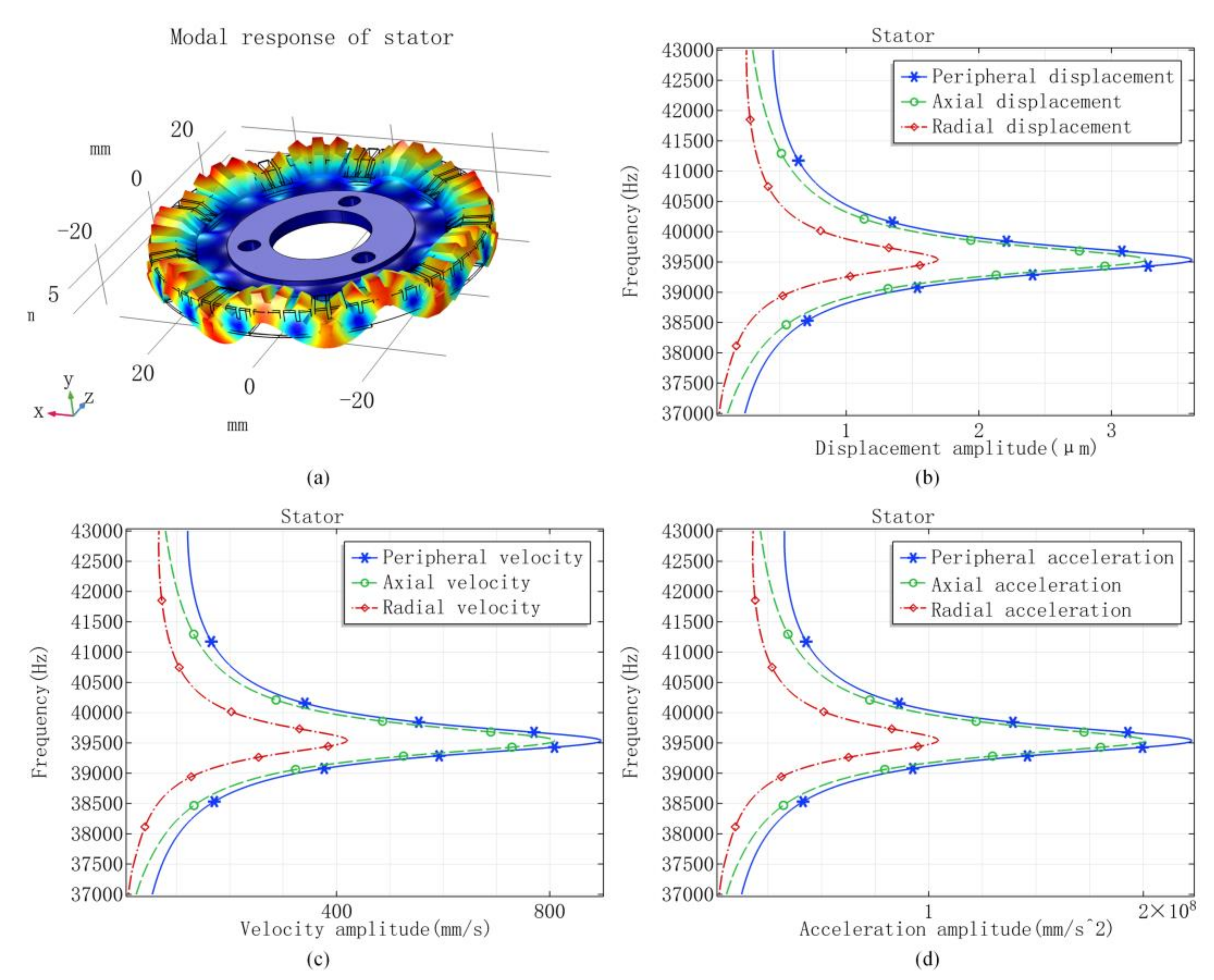
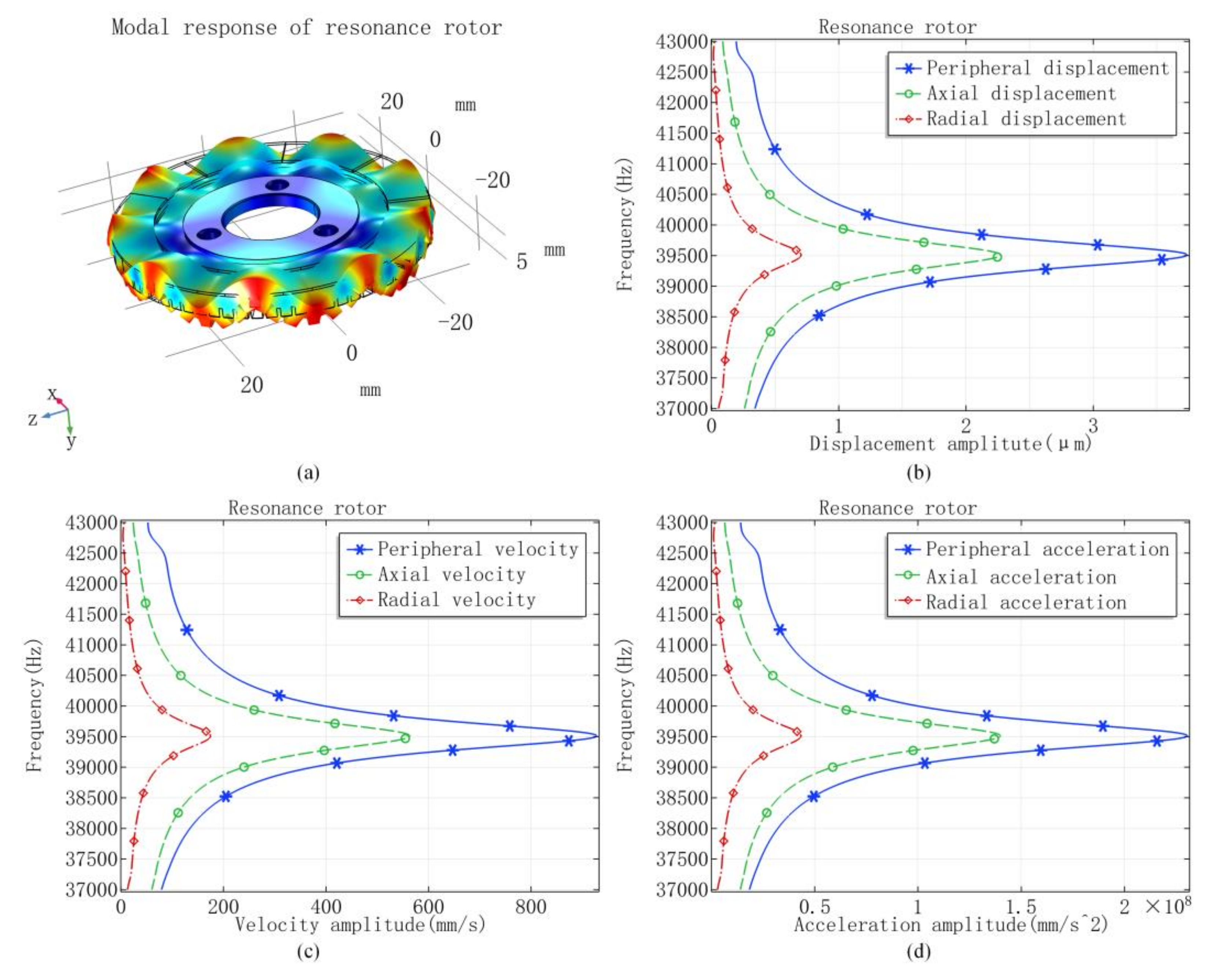
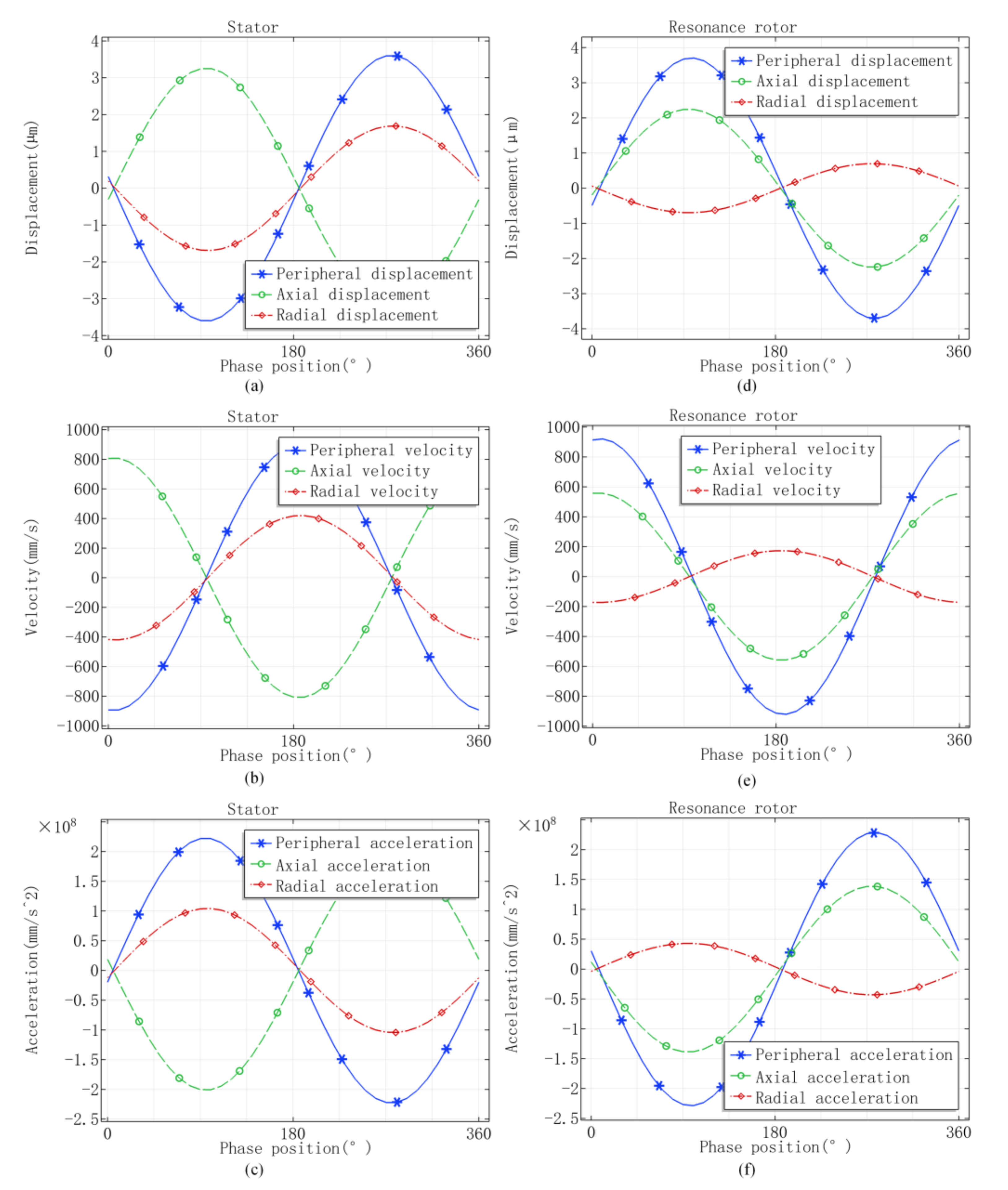
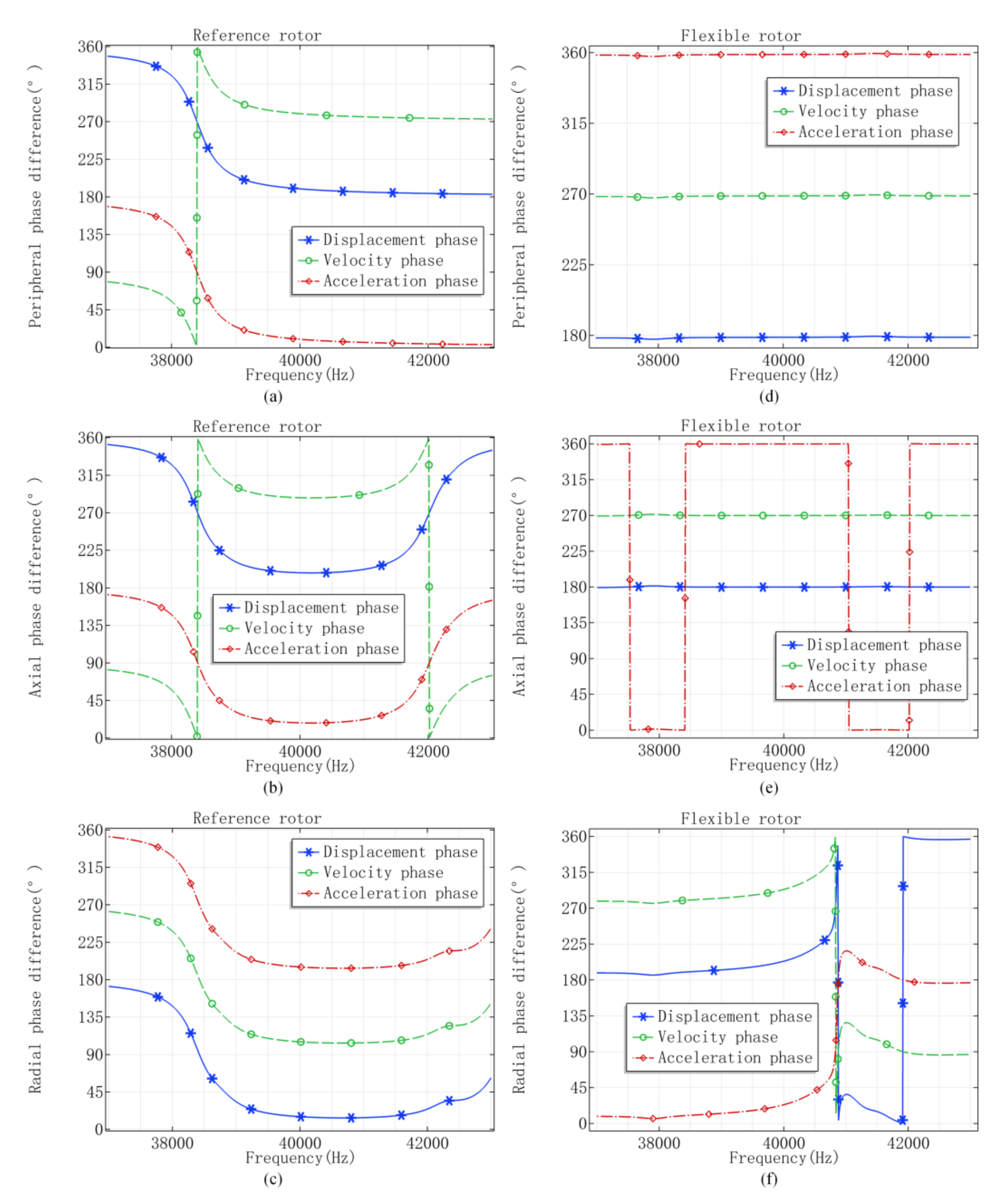
3.1. Numerical Results of FEM

On the basis of the boundary condition settings and the input parameters introduced in Section 2.1, the ninth modal frequency of the stator is computed as 39,535 Hz. The syntonic deformation is emerging around the outer ring as shown in Figure 1a, of which the mode shape contains nine nodal lines and zero nodal circles. Similarly, the ninth modal frequency of the resonance rotor is 39,514 Hz and the mode shape nephogram is shown in Figure 1b. The slight deviation of eigenfrequency between stator and resonance rotor is owing to the difference of the boundary constraints.
For the reference rotor, the ninth eigenfrequency occurs at 38,419 Hz and the difference in value to the stator is in excess of 1000 Hz. There is an interferential mode of vibration and the modal frequency is 38,756 Hz, which is closer to the nine eigenfrequency of the stator and the mode shape nephogram is shown in Figure 1c. For the flexible rotor, the ninth mode of vibration is not found in the sweeping frequency domain. The adjacent mode shapes to the stator 9th mode are occurring at 37,912 Hz and 41,136 Hz, respectively, with the mode shape nephogram shown in Figure 1e,f.
The amplitude response versus sweeping frequency is shown in Figure 2. When the drive frequency is equal to the ninth modal frequency, the ninth modal shape is energized obviously. As the drive frequency is away from ninth eigenfrequency, the responding amplitudes decline rapidly to lower values, and the ninth modal vibration becomes inconspicuous. The results are attributed to the spatial arrangement and polarization mode of the piezoelectric wafer and the modal structural design of the vibrator. The peripheral amplitude is slightly larger than the axial, both of which are much larger than the radial value. It is deduced that the driving force is generated from the peripheral vibration and restricted by the axial vibration, and the radial vibration wastes energy, reducing the output efficiency of the rotary piezoelectric motor.
The modal response of the resonance rotor is shown in Figure 3. The peak response occurs when the drive frequency is nearby the ninth eigenfrequency of the resonance rotor, which is almost the same as the modal frequency of the stator. Similar as the stator, the radial maximum values are much smaller than the peripheral and axial ones. Take the displacement response, for instance; the peripheral peak value is larger than value of the stator. Both the axial and radial peak value are smaller than the stator ones with the difference of 1 μm. The results show that the responding amplitudes of the resonance rotor have the same order of magnitude as the stator, which is required by the traveling waves engaging with each other.
As the drive frequency equals the ninth eigenfrequency of the stator, the vibration responses of stator particle within one oscillatory period are calculated and shown in Figure 4a–c. The results present that the displacement field is lagging to the velocity field with the phase difference of π / 2 , as well as the velocity field lagging to the acceleration filed with the same phase difference. When the axial deformation is oriented to the top transverse plane of stator teeth, the peripheral velocity of the contact particle is a tangent to the virtual circle along anticlockwise direction.
When the resonance rotor is excited by the stator, the variation of the field responses within one oscillatory period is calculated and shown in Figure 4d–f. The contact particle is moving anticlockwise peripherally as the axial displacement is towards the contact interface. The judgment of vibration direction is the foundation for deducing the wave meshing condition at the contact interface.
The phase difference between the vibrational response and excitation is calculated and shown in Figure 5a–c for the stator. The results illustrate that the displacement phase difference is approximately equal to π / 2 as the drive frequency approaches the ninth eigenfrequency. When the drive frequency sweeps from 37,000 Hz to 43,000 Hz, the velocity response is ahead of the displacement response with the phase difference of π / 2 , and the acceleration response is ahead of the velocity response.
Given the results of resonance rotor shown in Figure 5d–f, the velocity and acceleration responses keep ahead of the displacement response with the phase difference of π / 2 and π , respectively. From the phase difference between the response and the excitation, the displacement phase difference is approximately equal to π / 2 when the drive frequency is approaching the ninth eigenfrequency. When the drive frequency is growing to 43,000 Hz, the other mode shape would be excited with the corresponding modal frequency far away from the ninth vibration modes.
The ninth mode shape is also generated at the reference rotor as the drive frequency equals the ninth eigenfrequency of the stator, with the response nephogram shown in Figure 6a. From Figure 6b–d, the peak values of vibration response are occurring at 38,419 Hz, which is the ninth eigenfrequency of the reference rotor rather than the stator. The axial displacement amplitude is less than 0.5 μm when the drive frequency equals the ninth eigenfrequency of the stator, which is much smaller than the value of the stator, leading to the weak meshing effect for the double traveling waves.
The vibration response of the flexible rotor is shown in Figure 7 and there is not the evident peak response as the drive frequency sweeps from 37,000 to 43,000 Hz. It is consistent with the eigenfrequency solution that the ninth model shape is not occurring. When the drive frequency equals the ninth modal frequency of stator, the axial displacement is less than 0.5 μm and the peripheral displacement is less than 0.1 μm as well as the velocity and the acceleration are also much smaller than the values of stator. The wave meshing effect could be neglected when the piezoelectric motor employs the flexible rotor.
The field responses of the reference rotor within one period of vibration is shown in Figure 8a–c, and the values of the flexible rotor is shown in Figure 8d–f. The results present the slight axial vibration and the drive force generated by the rotors could be neglected.
The phase difference between vibration response and excitation for the reference rotor and flexible rotor is shown in Figure 9a–c and Figure 9d–f, respectively. The results further illustrate that the natural vibration is occurring at 38,419 Hz for the reference rotor and the vibration response of the flexible rotor is throughout feeble from 37,000 to 43,000 Hz. The saltation of the phase curves at the specific frequencies is consistent with the modal frequency analysis for both the rotors.

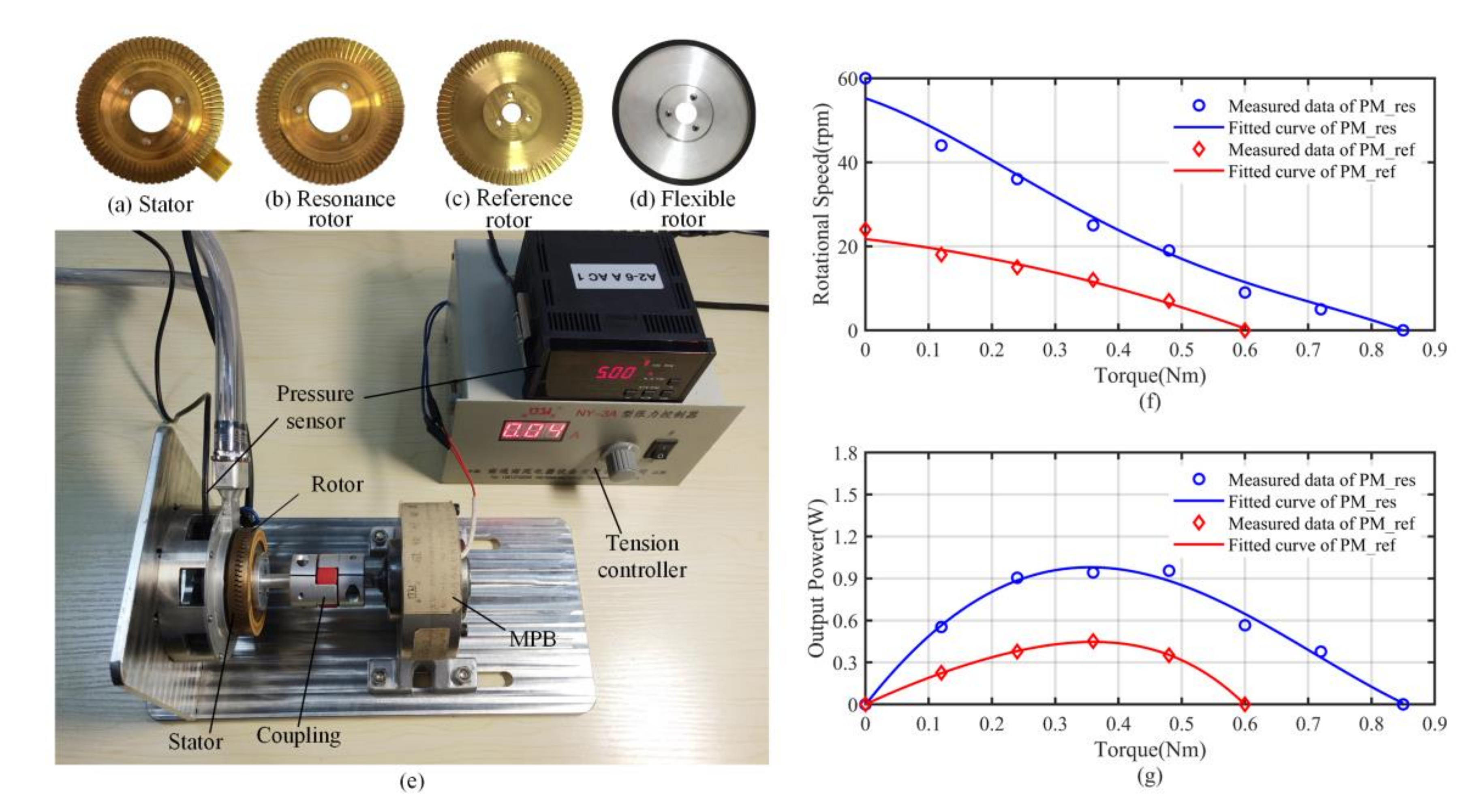
3.2. Prototype Experimental Results

To verify the meshing effectiveness of double traveling waves, the prototype experiment is executed by employing the resonance rotor and the reference rotor. According to the numerical results of the vibrators, the piezoelectric motor with resonance rotor (PM_res) is driven by the double traveling waves and the piezoelectric motor with reference rotor (PM_ref) is driven by the single traveling wave of the stator. The experimental device is set up as shown in Figure 10e. A magnetic powder brake (MPB) driven by a specialized tension controller is used as the torque load and a laser velocimeter is used to measure the rotational speed. The stator and three rotors are exhibited in Figure 10a–d.
Adjusting the drive frequency to the ninth modal frequency of the stator, output characteristic curves of the motors are measured and exhibited in Figure 10f. The measured results present that the rotational speed of PM_res is almost twice PM_ref, which is owing to the superimposed drive of the contact particles. The maximal torque of PM_res is also larger than PM_ref, which benefits from the opposite vibrational direction of the contact particles. Calculated from the values of the rotational speed and corresponding torque, the output power is calculated and shown in Figure 10g, illustrating that the meshing drive by double traveling waves is conducive to boost the motors’ power.

3.3. Discussion

From the mode shape analysis, we find that the ninth eigenfrequency of the resonance rotor is very close to the stator, while the value of reference rotor is far away from the stator with the difference of 1116 Hz, especially the ninth mode shape does not exist for the flexible rotor within the sweeping range. Because of the ring structure of all the vibrators and the bending vibration, the peripheral amplitude is slightly larger than the axial value and the radial amplitude is much smaller than the peripheral and axial value. It is deduced that the driving force is generated from the peripheral vibration, restricted by the axial vibration and the contact interface between the stator and the rotor. The radial vibration wasting energy brings down the output efficiency of the rotary piezoelectric motor.
As listed in Table 3, the amplitude responses of the reference rotor and flexible rotor are far less than the values of the stator. It indicates that the adjacent disturbing modes would restrain the vibration response excited by the stator, leading to the weak meshing effect of the traveling waves. Therefore, if the reference rotor or flexible rotor is employed by a piezoelectric motor, the vibrational analysis of the rotor can be omitted and the traveling wave generated by the stator is the principally concerned.
According to the analysis of Figure 5 and Figure 9, the displacement phase of resonance rotor has an approximate π / 2 lag behind the stator at the ninth modal frequency, whereas the phase difference is about π for the reference rotor and flexible rotor. The meshing mechanism of two traveling waves generated by the stator and resonance rotor could be illustrated as in Figure 11.
When the axial displacement of the stator and resonance rotor is uniformly oriented to the contact interface, the peripheral velocity of the stator is positive and the peripheral velocity of resonance rotor is negative, which is consistent with Figure 4. If ignoring the sliding friction of the interface, the relative velocity between the contact particles of the stator and resonance rotor is zero and could be described as
v r o t o r + v r o t o r _ p = v s t a t o r + v s t a t o r _ p
v r o t o r = v s t a t o r _ p v r o t o r _ p
where v r o t o r is the linear velocity of the rotor, v s t a t o r is the linear velocity of the stator and the value is zero, v r o t o r _ p is the tangential velocity of the rotor contact particle, v s t a t o r _ p is the tangential velocity of the stator contact particle. Because the peripheral velocity of the resonance rotor is close to the value of the stator, the linear velocity of the rotor is almost twice the value of the stator’s contact particle, which is verified by the experimental results.
Both the axial displacement of the stator and resonance rotor is oriented to the contact interface and the orientation of the axial velocity is the opposite. The axial amplitude response of the resonance rotor is smaller than the value of the stator, as shown in Table 3. The output torque T of the proposed motor is qualitatively described as
T = μ F A x i a l r = μ r ( F A x i a l _ S t a + F A x i a l _ R e s ) < 2 μ r F A x i a l _ S t a
where μ is the frictional coefficient of the contact interface, F A x i a l is the total axial force, F A x i a l _ S t a is the axial force generated by the vibration of stator, F A x i a l _ S t a is the axial force generated by the vibration of resonance rotor.
The meshing mechanism of traveling waves could be compared with the highly efficient driving of matching gears. The contact particles at the interface is similar to the pitch points of matching gears. The investigation is beneficial to enhancing the output capability of the rotary piezoelectric motors and propelling the industrial application of piezoelectric actuation in the fields of precision drive and ultrasonic machining. Nevertheless, the general principle of structural design for a special eigenfrequency and the underlying mechanical model are still required for the prospective development.

4. Conclusions

In this work, the meshing mechanism of a double traveling wave generated at the stator and resonance rotor is investigated. Based on the theoretical analysis of traveling wave generation and bending vibration of the equivalent simply supported beam, the finite element method is used to calculate the frequency-domain characterization by employing the resonance rotor, reference rotor and flexible rotor. As the modal frequency of the reference rotor and flexible rotor is far away from the stator, the ninth mode shape could be faintly energized by the vibration of the stator, of which the response amplitudes are much smaller than the stator and resonance rotor. Because the ninth modal frequency of the stator and resonance rotor are very close, the ninth mode shape and traveling wave of the resonance rotor can be easily energized using the vibration of the stator as the excitation source. From the computed results of the stator and resonance rotor, the peripheral amplitude of the contact particle is larger than the axial value, explaining that the drive force is generated by the peripheral vibration but subjected to the axial vibration. When the drive frequency is equal to the ninth modal frequency, the resonance rotor’s phase is lagging behind the stator of π / 2 while the value for the other rotors is π . By analyzing the vibrational orientation of contact particles in the peripheral and axial directions, the meshing principle of double traveling waves is discussed graphically. The formulas of the motor’s speed and torque are developed and verified by the experimental results. The work is different from the traditional rotary piezoelectric motor utilizing single traveling waves, which is conducive to the principle innovation and industrial application of the piezoelectric actuators.

Author Contributions

Conceptualization and methodology, D.A. and W.H.; software and visualization, W.L. and J.X.; writing—original draft preparation, D.A, W.L. and J.X.; writing—review and editing, X.L. and Z.L.; supervision, W.H. All authors have read and agreed to the published version of the manuscript.

Funding

This research was funded by Science and Technology Planning Project of Guangzhou, China (No. 202002030418), Key Project of Basic and Applied Basic Research Foundation of Guangdong Province, China (No. 2019B1515120017), National Natural Science Foundation of China (52075108,51975136).

Conflicts of Interest

The authors declare no conflict of interest.

References

  1. Storck, H.; Littmann, W.; Wallaschek, J.; Mracek, M. The Effect of Friction Reduction in Presence of Ultrasonic Vibrations and Its Relevance to Travelling Wave Ultrasonic Motors. Ultrasonics 2002, 40, 379–383. [Google Scholar] [CrossRef]
  2. Giraud, F.; Semail, B. A Torque Estimator for a Traveling Wave Ultrasonic Motor-Application to an Active Claw. IEEE Trans. Ultrason. Ferroelectr. Freq. Control 2006, 53, 1468–1477. [Google Scholar] [CrossRef] [Green Version]
  3. Chen, X.F.; Huang, W.Q.; Luo, J.Q.; Xu, J.J. Design of a Kind of Non-Resonant Linear Piezoelectric Motor. AMM 2013, 459, 418–423. [Google Scholar] [CrossRef]
  4. Chen, X.; Lu, Q.; Huang, W.; Wang, Y. Working Mechanism of Nonresonance Friction in Driving Linear Piezoelectric Motors with Rigid Shaking Beam. Math. Probl. Eng. 2018, 2018, 1–10. [Google Scholar] [CrossRef]
  5. Peng, Y.; Peng, Y.; Gu, X.; Wang, J.; Yu, H. A Review of Long Range Piezoelectric Motors Using Frequency Leveraged Method. Sens. Actuators A Phys. 2015, 235, 240–255. [Google Scholar] [CrossRef]
  6. Cheon, S.-K.; Jeong, S.-S.; Ha, Y.-W.; Lee, B.-H.; Park, J.-K.; Park, T.-G. Driving Characteristics of an Ultrasonic Rotary Motor Consisting of Four Line Contact Type Stators. Ceram. Int. 2015, 41, S618–S624. [Google Scholar] [CrossRef]
  7. Li, S.; Li, D.; Yang, M.; Cao, W. Parameters Identification and Contact Analysis of Traveling Wave Ultrasonic Motor Based on Measured Force and Feedback Voltage. Sens. Actuators A Phys. 2018, 284, 201–208. [Google Scholar] [CrossRef]
  8. An, D.; Yang, M.; Zhuang, X.; Yang, T.; Meng, F.; Dong, Z. Dual Traveling Wave Rotary Ultrasonic Motor with Single Active Vibrator. Appl. Phys. Lett. 2017, 110, 143507. [Google Scholar] [CrossRef]
  9. An, D.; Huang, W. Inherent Mechanism of Frequency Drift Affected by Constraint Conditions for Rotary Piezoelectric Motors. Rev. Sci. Instrum. 2020, 91, 035002. [Google Scholar] [CrossRef] [PubMed]
  10. Tang, M.; Bao, Q.; Zhang, J.; Ning, Q.; Chen, C.; Huang, J.; Wu, C. Design and Experimental Verification of a PZT Pump with Streamlined Flow Tubes. Appl. Sci. 2019, 9, 3881. [Google Scholar] [CrossRef] [Green Version]
  11. Bao, Q.; Zhang, J.; Tang, M.; Huang, Z.; Lai, L.; Huang, J.; Wu, C. A Novel PZT Pump with Built-in Compliant Structures. Sensors 2019, 19, 1301. [Google Scholar] [CrossRef] [PubMed] [Green Version]
  12. He, X.-T.; Yang, Z.-X.; Li, Y.-H.; Li, X.; Sun, J.-Y. Application of Multi-Parameter Perturbation Method to Functionally-Graded, Thin, Circular Piezoelectric Plates. Mathematics 2020, 8, 342. [Google Scholar] [CrossRef] [Green Version]
  13. Liu, T.; Li, C.; Wang, C.; Lai, J.W.; Cheong, K.H. A Simple-FSDT-Based Isogeometric Method for Piezoelectric Functionally Graded Plates. Mathematics 2020, 8, 2177. [Google Scholar] [CrossRef]
  14. Yuan, T.; Dong, X.; Shekhani, H.; Li, C.; Maida, Y.; Tou, T.; Uchino, K. Driving an Inductive Piezoelectric Transducer with Class E Inverter. Sens. Actuators A Phys. 2017, 261, 219–227. [Google Scholar] [CrossRef]
  15. Jang, J.H.; Chang, C.; Rasumssen, M.F.; Brenner, K.; Stedman, Q.; Ergun, A.S.; Khuri-Yakub, B.T. Dual-Mode Capacitive Micromachined Ultrasonic Transducer Arrays for High Intensity Focused Ultrasound and Imaging. J. Acoust. Soc. Am. 2018, 144, 1698. [Google Scholar] [CrossRef]
  16. Sun, X.; Li, S.; Dun, X.; Li, D.; Li, T.; Guo, R.; Yang, M. A Novel Characterization Method of Piezoelectric Composite Material Based on Particle Swarm Optimization Algorithm. Appl. Math. Model. 2019, 66, 322–331. [Google Scholar] [CrossRef]
  17. Guo, R.; Li, S.; An, D.; Han, T.; Chen, J.; Cao, W. Comprehensive Analysis of Mn:PIN-PMN-PT Single Crystals for Class IV Flextensional Transducer. Ceram. Int. 2018, 44, 2864–2868. [Google Scholar] [CrossRef]
  18. Wu, J.; Mizuno, Y.; Nakamura, K. Structural Parameter Study on Polymer-Based Ultrasonic Motor. Smart Mater. Struct. 2017, 26, 115022. [Google Scholar] [CrossRef]
  19. Wu, J.; Mizuno, Y.; Nakamura, K. Polymer-Based Ultrasonic Motors Utilizing High-Order Vibration Modes. IEEE/ASME Trans. Mechatron. 2018, 23, 788–799. [Google Scholar] [CrossRef]
  20. Cao, T.; Li, X.; Wang, B.; Mi, Y.; Zhao, G.; Twiefel, J.; Wu, D. Viscoelastic Analytical Model and Design of Polymer-Based Bimodal Piezoelectric Motor. Mech. Syst. Signal Process. 2020, 145, 106960. [Google Scholar] [CrossRef]
  21. Shi, M.; Liu, X.; Feng, K.; Zhang, K. Experimental and Numerical Investigation of a Self-Adapting Non-Contact Ultrasonic Motor. Tribol. Int. 2021, 153, 106624. [Google Scholar] [CrossRef]
  22. Yin, Z.; Dai, C.; Cao, Z.; Li, W.; Chen, Z.; Li, C. Modal Analysis and Moving Performance of a Single-Mode Linear Ultrasonic Motor. Ultrasonics 2020, 108, 106216. [Google Scholar] [CrossRef] [PubMed]
  23. Nakamura, T.; Yashiro, D.; Yubai, K.; Komada, S. Torque Control of a Series Elastic Actuator Using an Ultrasonic Motor with Angular-velocity Saturation. Electr. Eng. Jpn. 2020, eej.23297. [Google Scholar] [CrossRef]
  24. Koc, B. Operating Frequency Tracking of Single Phase Driving Type Piezoelectric Motors. J. Electroceram. 2009, 23, 262. [Google Scholar] [CrossRef]
  25. Mustafa, A.; Morita, T. Fundamental Study of Preload Control for Rotary Ultrasonic Motors. In Proceedings of the 2018 JSPE Semestrial Meeting, Hachioji, Tokyo, Japan, 15–17 March 2018; pp. 713–714. Available online: https://www.jstage.jst.go.jp/article/pscjspe/2018S/0/2018S_713/_article/-char/ja/.
  26. Mustafa, A.; Morita, T. Efficiency Optimization of Rotary Ultrasonic Motors Using Extremum Seeking Control with Current Feedback. Sens. Actuators A Phys. 2019, 289, 26–33. [Google Scholar] [CrossRef]
  27. Lu, X.; Hu, J.; Zhao, C. Analyses of the Temperature Field of Traveling-Wave Rotary Ultrasonic Motors. Ieee Trans. Ultrason. Ferroelectr. Freq. Control 2011, 58, 2708–2719. [Google Scholar] [CrossRef] [PubMed]
  28. Lu, X.; Hu, J.; Yang, L.; Zhao, C. Principle and Experimental Verification of Novel Dual Driving Face Rotary Ultrasonic Motor. Chin. J. Mech. Eng. 2013, 26, 1006–1012. [Google Scholar] [CrossRef]
  29. Li, S.; Ou, W.; Yang, M.; Guo, C.; Lu, C.; Hu, J. Temperature Evaluation of Traveling-Wave Ultrasonic Motor Considering Interaction between Temperature Rise and Motor Parameters. Ultrasonics 2015, 57, 159–166. [Google Scholar] [CrossRef]
  30. Ou, W.; Yang, M.; Meng, F.; Xu, Z.; Zhuang, X.; Li, S. Continuous High-Performance Drive of Rotary Traveling-Wave Ultrasonic Motor with Water Cooling. Sens. Actuators A Phys. 2015, 222, 220–227. [Google Scholar] [CrossRef]
  31. Hagood, N.W.; McFarland, A.J. Modeling of a Piezoelectric Rotary Ultrasonic Motor. IEEE Trans. Ultrason. Ferroelectr. Freq. Control 1995, 42, 210–224. [Google Scholar] [CrossRef]
  32. Fang, Z.; Yang, T.; Zhu, Y.; Li, S.; Yang, M. Velocity Control of Traveling-Wave Ultrasonic Motors Based on Stator Vibration Amplitude. Sensors 2019, 19, 5326. [Google Scholar] [CrossRef] [PubMed] [Green Version]
  33. Mohd Romlay, F.R.; Wan Yusoff, W.A.; Mat Piah, K.A. Increasing the Efficiency of Traveling Wave Ultrasonic Motor by Modifying the Stator Geometry. Ultrasonics 2016, 64, 177–185. [Google Scholar] [CrossRef] [Green Version]
  34. Peng, T.; Shi, H.; Liang, X.; Luo, F.; Wu, X. Experimental Investigation on Sandwich Structure Ring-Type Ultrasonic Motor. Ultrasonics 2015, 56, 303–307. [Google Scholar] [CrossRef] [PubMed]
  35. Chen, W.; Shi, S.; Liu, Y.; Li, P. A New Traveling Wave Ultrasonic Motor Using Thick Ring Stator with Nested PZT Excitation. IEEE Trans. Ultrason. Ferroelectr. Freq. Control 2010, 57, 1160–1168. [Google Scholar] [CrossRef]
  36. Hagedorn, P.; Wallaschek, J. Travelling Wave Ultrasonic Motors, Part I: Working Principle and Mathematical Modelling of the Stator. J. Sound Vib. 1992, 155, 31–46. [Google Scholar] [CrossRef]
  37. Hagedorn, P.; Wallaschek, J.; Konrad, W. Travelling Wave Ultrasonic Motors, Part II: A Numerical Method For The Flexural Vibrations Of The Stator. J. Sound Vib. 1993, 168, 115–122. [Google Scholar] [CrossRef]
  38. Zhao, C. Ultrasonic Motors Technologies and Applications; Springer: Berlin/Heidelberg, Germany, 2011. [Google Scholar]
  39. Rajkumar, R.; Nogai, T. A New Method of Improving the Torque of a Travelling Wave Ultrasonic Motor. In Proceedings of the 1999 IEEE/ASME International Conference on Advanced Intelligent Mechatronics, Atlanta, GA, USA, 19–23 September 1999; pp. 109–113. [Google Scholar]
  40. Bai, D.; Ishii, T.; Nakamura, K.; Ueha, S.; Yonezawa, T.; Takahashi, T. An Ultrasonic Motor Driven by the Phase-Velocity Difference between Two Traveling Waves. IEEE Trans. Ultrason. Ferroelectr. Freq. Control 2004, 51, 680–685. [Google Scholar] [PubMed]
  41. Dong, Z.; Yang, M.; Chen, Z.; Xu, L.; Meng, F.; Ou, W. Design and Performance Analysis of a Rotary Traveling Wave Ultrasonic Motor with Double Vibrators. Ultrasonics 2016, 71, 134–141. [Google Scholar] [CrossRef]
  42. Sana, M.; Mustahsan, M. Finite Element Approximation of Optimal Control Problem with Weighted Extended B-Splines. Mathematics 2019, 7, 452. [Google Scholar] [CrossRef] [Green Version]
  43. Vlase, S.; Negrean, I.; Marin, M.; Nastac, S. Kane’s Method-Based Simulation and Modeling Robots with Elastic Elements, Using Finite Element Method. Mathematics 2020, 8, 805. [Google Scholar] [CrossRef]
  44. Rao, S.S. Mechanical Vibrations, 5th ed.; Prentice Hall: Upper Saddle River, NJ, USA, 2011. [Google Scholar]
Figure 1. Comparison of mode shapes for stator and rotors. (a) 9th modal shape of stator. (b) 9th modal shape of resonance rotor. (c) Adjacent modal shape of reference rotor. (d) 9th modal shape of reference rotor. (e) Adjacent modal shape of flexible rotor. (f) The other adjacent modal shape of flexible rotor.
Mathematics 09 00445 g001
Figure 2. Amplitude response of the stator in the peripheral, axial and radial directions. (a) Modal response nephogram of stator. (b) Displacement amplitude versus sweeping drive frequency. (c) Velocity amplitude versus sweeping drive frequency. (d) Acceleration amplitude versus sweeping drive frequency.
Mathematics 09 00445 g002
Figure 3. Amplitude response of resonance rotor in the peripheral, axial and radial directions. (a) Modal response nephogram of resonance rotor. (b) Displacement amplitude versus sweeping drive frequency. (c) Velocity amplitude versus sweeping drive frequency. (d) Acceleration amplitude versus sweeping drive frequency.
Mathematics 09 00445 g003
Figure 4. Modal response of stator and resonance rotor within one oscillatory period. (a) Periodical displacement response of stator. (b) Periodical velocity response of stator. (c) Periodical acceleration response of stator. (d) Periodical displacement response of resonance rotor. (e) Periodical velocity response of resonance rotor. (f) Periodical acceleration response of resonance rotor.
Mathematics 09 00445 g004
Figure 5. Variation of phase difference of stator and resonance rotor as sweeping frequency. (a) Peripheral phase difference of stator. (b) Axial phase difference of stator. (c) Radial phase difference of stator. (a) Peripheral phase difference of resonance rotor. (b) Axial phase difference of resonance rotor. (c) Radial phase difference of resonance rotor.
Mathematics 09 00445 g005
Figure 6. Amplitude response of reference rotor in the peripheral, axial and radial directions. (a) Modal response nephogram of reference rotor. (b) Displacement amplitude versus sweeping drive frequency. (c) Velocity amplitude versus sweeping drive frequency. (d) Acceleration amplitude versus sweeping drive frequency.
Mathematics 09 00445 g006
Figure 7. Amplitude response of the flexible rotor in peripheral, axial and radial directions. (a) Modal response nephogram of flexible rotor. (b) Displacement amplitude versus sweeping drive frequency. (c) Velocity amplitude versus sweeping drive frequency. (d) Acceleration amplitude versus sweeping drive frequency.
Mathematics 09 00445 g007
Figure 8. Modal response of reference rotor and flexible rotor within one oscillatory period. (a) Periodical displacement response of reference rotor. (b) Periodical velocity response of reference rotor. (c) Periodical acceleration response of reference rotor. (d) Periodical displacement response of flexible rotor. (e) Periodical velocity response of flexible rotor. (f) Periodical acceleration response of flexible rotor.
Mathematics 09 00445 g008
Figure 9. Variation of phase difference of reference rotor and flexible rotor as sweeping frequency. (a) Peripheral phase difference of reference rotor. (b) Axial phase difference of reference rotor. (c) Radial phase difference of reference rotor. (d) Peripheral phase difference of flexible rotor. (e) Axial phase difference of flexible rotor. (f) Radial phase difference of flexible rotor.
Mathematics 09 00445 g009
Figure 10. Prototype experiments and output performance curves. (a) Stator. (b) Resonance rotor. (c) Reference rotor. (d) Flexible rotor. (e) Experimental device. (f) Speed-torque curve. (g) Power-torque curve.
Mathematics 09 00445 g010
Figure 11. Meshing drive mechanism of double traveling waves.
Mathematics 09 00445 g011
Table 1. Material composition and structural parameters of stator and rotors.
VibratorsMaterialsOuter Diameter (mm)Inner Diameter (mm)Total Height (mm)
StatorPhosphor bronze & PZT-8H60184.5 + 0.5
Resonance rotor184.5 + 0.5
Reference rotorPhosphor bronze85
Flexible rotorAluminum85
Table 2. Materials attribute of vibrators.
ParametersPhosphor BronzeAluminumPZT-8H
Mass density (kg/m3)878027707600
Poisson’s ratio0.3410.3
Young’s modulus (N/m2)1.1E117.17E10
Table 3. Numerical results of vibrators by finite element method (FEM).
Calculated ResultsStatorResonance RotorReference RotorFlexible Rotor
9th modal frequency (Hz)39,53539,51438,419
Adjacent modal frequency (Hz)38,75637,912
41,136
Displacement amplitude (μm) 1Peripheral3.6083.7162.1390.466
Axial3.2582.2550.2430.085
Radial1.6910.6990.1050.020
Velocity amplitude (mm/s) 1Peripheral896.5923.1531.3115.9
Axial809.6560.360.4921.27
Radial420.3173.826.105.035
Acceleration amplitude (mm/s2) 1Peripheral2.227 × 1082.2931.319 × 1080.288 × 108
Axial2.011 × 1081.3910.150 × 1080.052 × 108
Radial1.044 × 1080.4310.064 × 1080.012 × 108
1 Driving frequency is equal to 9th modal frequency of stator.
Publisher’s Note: MDPI stays neutral with regard to jurisdictional claims in published maps and institutional affiliations.

