Article

Mutual Influence of Geometric Parameters and Mechanical Properties on Thermal Stresses in Composite Laminated Plates with Rectangular Holes

by
Mohammad Hossein Bayati Chaleshtari
1,
Mohammad Jafari
2,
Hadi Khoramishad
1 and
Eduard-Marius Craciun
3,*
1
School of Mechanical Engineering, Iran University of Science and Technology, Narmak, Tehran 16846-13114, Iran
2
Mechanical Engineering Department, Shahrood University of Technology, Shahrood 3619995161, Iran
3
Faculty of Mechanical, Industrial and Maritime Engineering, “Ovidius” University of Constanta, 900527 Constanta, Romania
*
Author to whom correspondence should be addressed.
Mathematics 2021, 9(4), 311; https://doi.org/10.3390/math9040311
Submission received: 31 December 2020 / Revised: 24 January 2021 / Accepted: 28 January 2021 / Published: 4 February 2021
(This article belongs to the Section Mathematical Physics)

Abstract

:
In this research, the mutual influence of the mechanical properties and geometric parameters on thermal stress distribution in symmetric composite plates with a quasi-rectangular hole subjected to uniform heat flux is examined analytically using the complex variable technique. The analytical solution is obtained based on the thermo-elastic theory and the Lekhnitskii’s method. Furthermore, by employing a suitable mapping function, the solution of symmetric laminates containing a circular hole is extended to the quasi-rectangular hole. The effect of important parameters including the stacking sequence of laminates, the angular position, the bluntness, and the aspect ratio of the hole and the flux angle in the stacking sequence of [45/−45]s for composite materials are examined in relation to the thermal stress distribution. The thermal insulated state and Neumann boundary conditions at the hole edge are taken into account. It is found out that the hole rotation angles and heat flux angle play key roles in obtaining the optimum thermal stress distribution around the hole. The present analytical method can well investigate the interaction of effective parameters on symmetric multilayer composites under heat flux.

1. Introduction

Composite laminates have great utilization in the manufacture of different structures. Thin composite plates as main elements in most recent structures have found widespread applications in industrial production [1,2]. In recent decades, the increasing requirements for the improved performance of structures has made designers interested in designing structural elements with optimal shapes [3,4]. Different shapes of holes in the structures are required to minimize the structures’ weight and supply accessibility other than the system parts [5,6]. In most cases, the hole is not created at the beginning of the initial design [7]. In order to achieve the desired design and provide the right potential to deal with mechanical damage, it is necessary to know in detail the distribution of stresses created around geometric discontinuities [8,9].

2. Literature Review

Many researchers have studied the stress distribution surrounding different holes in perforated laminates by applying different methods such as analytical and numerical approaches [10,11]. Lekhnitskii [12] used the complex variable technique to determine the stress functions and calculated the different stress components created surrounding the hole with different shapes located on the anisotropic plane. Florence and Goodier [13,14] developed the use of the complex variable approach to solve boundary value problems in two-dimensional (2D) thermoelasticity. They studied the stress distribution around circular and elliptical holes located on a linear elastic isotropic plate under constant heat flux. Using the complex variable method and presenting suitable potential functions for different loading conditions such as thermal and mechanical loadings, Hasebe [15] investigated a variety of problems of linear elastic isotropic plates with geometric discontinuities that were subjected to heat flux. Tarn and Wang [16] calculated the distribution of thermal stresses in an anisotropic elastic plane weakened by a circular or solid inclusion using the complex variable method and Lekhnitskii’s complex potential functions. They applied the assumptions of plane stress and plane strain. Chao and Chang [17] used the complex variable technique to determine the thermal stresses surrounding circular inclusion in an unlimited plane subject to steady temperature change. By applying boundary conditions for plastic deformation, Wang et al. [18] studied the thermal elastic–plastic stress behavior in a composite plate under thermal loading based on differential relations for anisotropic plane stress. The influences of the material properties and temperature change as the most important parameters on stress created in the plate were examined. Ukadgaonker and Rao [19] used the complex variable approach to compute the stress created surrounding different holes in symmetric laminates. The stacking sequence and hole orientation were considered as the most important parameters that affect the stress distribution around the holes. Sharma [20] exerted the complex variable approach to provide a general solution for calculating the stresses surrounding a non-circular hole in a laminated composite under arbitrary biaxial loading with different lay-ups. Goyat et al. [21] investigated the influence of using functionally graded material (FGM) layer to reduce the maximum values of stress in a plate with a quasi-rectangular hole subject to mechanical loading. Young’s modulus and layer thickness as the main parameters were studied. Dai et al. [22] studied stress created in an infinite plane with a special state of the circular hole by applying the Gurtin–Murdoch method. Damghani et al. [23] investigated the effect of stacking sequence and laminate homogenized stiffness parameters on stress distribution around an elliptical hole in an unlimited laminate subject to membrane loading by using the complex variable technique.
Choi [24] investigated the stress intensity factor (SIF) in an infinite orthotropic plane with two parallel cracks under a constant heat flux. Xiao et al. [25] analyzed the behavior of cracked circular hole located in a plate subject to shear loading by using the complex variable technique and conformal mapping function. They investigated the effect of the interaction of the cracks on the SIF and the strain energy release rate. Guo and Noda [26] applied the perturbation method to calculate the thermal stress distribution in an FGM cylinder. The analytical solution was used to derive the transient thermal stresses relation and the thermal diffusion relation for a thin FGM plate. Khan et al. [27] studied the thermal stress distribution in homogenized and heterogeneous composites plate in different temperatures and displacements due to coupled thermal and mechanical loadings. Zhang et al. [28] computed the thermal stress around a hole in metallic plates under a strict geometrical boundary state subject to the high values of temperature. The curvature of sharp corners near critical areas as a significant parameter was studied. Li et al. [29] presented an experimental solution to determine the influence of temperature on carbon/polyimide composite behavior in symmetric laminated plates containing a circular hole subject to thermo-mechanical loading. They tried to obtain the inter-laminar stress analysis at different temperatures by using Abaqus software. Mahmoudi and Atefi [30] presented a general solution to derive the thermal stress distribution in a hollow cylinder under periodic time-varying thermal loading. They analyzed temperature change behavior as an important function by using the Fourier series method. Jafari et al. [31,32] utilized the complex variable technique to discuss the thermo-elastic stresses in an infinite metallic plate with a non-circular hole subjected to a steady heat flux. Rasouli and Jafari [33] developed the Lekhnitskii’s solution to calculate the thermal stress created in an anisotropic plate weakened by elliptic holes and under a steady heat flux. Important parameters such as hole rotation angle and heat flux angle were investigated in this study. Using the complex variable technique, Chao et al. [34] offered an analytical solution to calculate the stress distribution surrounding two inclusions in the shape of circle located in an infinite plate subjected to a constant heat flux. Chao and Gao [35] used Lekhnitskii’s approach to establish a comprehensive analytical method for an infinite composite laminate with an elliptic inclusion under constant heat flux. Chiang [36] studied stress distribution surrounding a circular hole in cubic crystals material under thermal loading. Jafari et al. [37,38] investigated the stress and displacement fields in the orthotropic plates with a rectangular hole subject to a uniform heat flux.
The main purpose of this article is to study the interaction of significant parameters on the behavior of multi-layer composite laminate containing a rectangular hole made of graphite/epoxy and E-glass/epoxy wet under constant heat flux. For this purpose, an analytical solution based on the complex variable approach has been used. Moreover, the important parameters such as heat flux angle, hole rotation angles, bluntness, and hole aspect ratio were examined for graphite/epoxy and E-glass/epoxy wet materials in the stacking sequence of [45/−45]s.

3. Analytical Solution

The symmetric laminated composite plates with a rectangular hole under a remote constant heat flux q subjected to steady-state condition were considered. The rectangular hole with an insulated edge was assumed. Since the ratio of the dimensions of the plate to the hole is considered very large, then the theory of infinite plates can be used. The amount of rotation of the hole around the axis perpendicular to the plane and the orientation of the hole relative to the horizontal axis has been called the rotation angle or hole orientation (β), which is shown in Figure 1.
In the absence of a heat source, it can be safely stated that the greatest stress happens at the hole edges. Moreover, examining the boundary conditions governing the problem at the hole boundary in the polar coordinate system (ρ,θ), as shown in Figure 1, we conclude that the tangential stress (σθ) is the only stress created around the hole. In the present analysis, the assumption of plane stress is used, and the deformations are considered small. According to the classical laminated-plate theory (CLPT), it can be proved for a symmetric laminated plate that only the [ A i j ] matrix was remained as extensional stiffness. By introducing the stress function U ( x , y ) , the compatibility relationship of an anisotropic plate is defined in terms of the stress function as Equation (1) [12]:
a 11 4 U y 4 2 a 16 4 U x y 3 + ( 2 a 12 + a 66 ) 4 U x 2 y 2 2 a 26 4 U x 3 y + a 22 4 U x 4 = α x 2 T y 2 + α x y 2 T x y α y 2 T x 2 .
In Equation (1), a i j are the components of the reduced compliance matrix of the symmetric laminate, and α x , α y , and α x y are the thermal expansion coefficients of the symmetric composite plate. The general solution of Equation (1) is defined as relation (2):
E = E ( h ) + E ( p ) .
E(h) and E(p) are homogeneous and particular parts, respectively. The homogeneous solution is derived using Lekhnitskii’s approach; by presenting the four linear first-order differential operators, Equation (1) is presented as Equation (3) [12]:
D 1 D 2 D 3 D 4 E ( h ) = 0 ,   D k = y s k x
where s k are the roots of the characteristic Equation (4):
a 11 s 4 2 a 16 s 3 + ( 2 a 12 + a 66 ) s 2 2 a 26 s + a 22 = 0 .
Lekhnitskii presented that the Equation (4) has four complex roots, including of two conjugate pairs s 1 = s 3 ¯ and s 2 = s 4 ¯ [12]. According to the roots of the characteristic equation, the homogeneous solution of Equation (1), ( E h ) can be written as follows:
E h = E 1 ( Z 1 ) + E 2 ( Z 2 ) + E 1 ( Z 1 ) ¯ + E 2 ( Z 2 ) ¯ + E ( p ) .
In Equation (5), E 1 and E 2 are holomorphic functions, E 1 ¯ and E 2 ¯ are their conjugates functions, and Z k have the following form Z k = x + s k y , (k = 1,2).
Now, the new stress function ( ψ ) is calculated using the stress function E h as Equation (6).
d E h d z = ψ 1 ( Z 1 ) + ψ 2 ( Z 2 ) + ψ 1 ( Z 1 ) ¯ + ψ 2 ( Z 2 ) ¯ + ψ ( p ) .
The plane stress components using Equations (5) and (6) in the stress function are given as Equation (7):
σ x = 2 R e { s 1 2 ψ 1 ( Z 1 ) + s 2 2 ψ 2 ( Z 2 ) } + 2 E ( p ) y 2 σ y = 2 R e { ψ 1 ( Z 1 ) + ψ 2 ( Z 2 ) } + 2 E ( p ) x 2 τ x y = 2 R e { s 1 ψ 1 ( Z 1 ) + s 2 ψ 2 ( Z 2 ) } 2 E ( p ) x y .
We denoted by ψ 1 ( Z 1 ) and ψ 2 ( Z 2 ) the derivatives of the holomorphic functions ψ 1 ( Z 1 ) and ψ 2 ( Z 2 ) with respect to the variables Z 1 and Z 2 , respectively.
As seen in Equation (8), the relationship between the temperature gradient T and the heat flux ( q ) is obtained by applying the Fourier law.
{ q } o f f = k o f f T o f f .
The off-axis thermal conductivity matrix in terms of fiber angle ( γ ) can be obtained as Equation (9):
k o f f = [ T ( γ ) ] k o n [ T ( γ ) ] [ T ( γ ) ] = [ c o s γ s i n γ 0 s i n γ c o s γ 0 0 0 1 ] .
The resultants of thermal conductivity coefficient along the laminate thickness can be obtained as shown in Equation (10):
[ K ] = 1 H l = 1 N L [ k ¯ ] l ( z l z l 1 ) .
where l is the number of layers and [ K ] is the resultant thermal conductivity matrix. In addition, in the absence of an interior heat source, the equation governing linear thermostatic can be expressed as follows [39]:
. q i = 0 , ( i   =   x , y , z ) .
Replacing Equation (8) into Equation (11), the thermal equation related to homogeneous anisotropic plates is displayed as shown in Equation (12).
K x 2 T x 2 + 2 K x y 2 T x y + K y 2 T y 2 = 0 .
In the above equation, the harmonic function T(x,y) implies the temperature distribution in the laminated composite plate. The solution of the aforementioned relationship can be considered as T = Et(x+st y), where st represents the roots of the characteristic equation (Equation (13)) [37]:
K y s t 2 + 2 K x y s t + K x = 0 .
It is proved that the above characteristic equation always has two conjugate roots, so the general solution can be written as follows:
T = E t ( Z t ) + E t ( Z t ) ¯ = 2 R e ( E t ( Z t ) ) Z t = x + s t y
in which E t is a holomorphic function. Using Equation (14) in Equation (1), the particular solution of the stress function Ep is given as follows [38]:
E ( p ) = 2 R e ( η E t ( Z t ) )
where
η = ( α y + α x y s t α x s t 2 ) a 11 s t 4 2 a 16 s t 3 + ( 2 a 12 + a 66 ) s t 2 2 a 26 s t + a 22 .
Moreover, upon the substitution of Equation (15) into Equation (7), the stress components and displacement field of the plate are written in terms of stress functions as Equation (17):
σ y = 2 R e { ψ 1 ( Z 1 ) + ψ 2 ( Z 2 ) } + 2 R e ( η ψ t ) , τ x y = 2 R e { s 1 ψ 1 ( Z 1 ) + s 2 ψ 2 ( Z 2 ) } 2 R e ( η s t ψ t ) u x = 2 R e k = 1 2 b k ψ k + 2 R e ( b t ψ t ) , u y = 2 R e k = 1 2 d k ψ k + 2 R e ( d t ψ t ) p k = a 11 s k 2 + a 12 a 16 s k , p t = η ( a 11 s t 2 + a 12 a 16 s t ) + a x q k = a 12 s k + a 22 s k a 26 , q t = η ( a 12 s t + a 22 s t a 26 ) + a y s t , k = 1 , 2 .
Based on Equation (17) and the displacement field [38], to achieve the stress components, it is necessary to derive the stress functions ψ i and ψ t . By considering the traction-free condition of the edge of the rectangular hole and also by considering the insulation of the hole edge, the stress functions ψ i and ψ t can be obtained [37].
Moreover, to study the thermal stress distribution in symmetric laminates with a rectangular hole, the conformal transferring functions w ( ξ ) = x + s k y (k = 1, 2, t) are utilized. The mapping function in terms of ξ is defined as shown in Equation (18).
Z k = w ( ξ ) = ( Ω 1 k ξ + Ω 2 k ξ 1 + Ω 3 k ξ n + Ω 4 k ξ n ) 2
in which Ω i k , ( i = 1 , 2 , 3 , 4 ) are outlined as below:
Ω 1 k = 1 2 [ ( 1 i c s k ) cos β ( i c + s k ) sin β ] , Ω 3 k = w 2 [ ( 1 + i s k ) cos β + ( i s k ) sin β ] Ω 2 k = 1 2 [ ( 1 + i c s k ) cos β + ( i c s k ) sin β ] , Ω 4 k = w 2 [ ( 1 i s k ) cos β ( i + s k ) sin β ] .
In Equation (19), the parameter c indicates the amount of elongation in one direction, and w shows the amount of curvature of the hole corners (bluntness parameter). The states 0 ≤ w < 1/n verify that the form of the hole does not have loops. The parameter n determines the geometry of hole that in this paper is equal to 3. Figure 2 illustrates the influence of the values of w on the shape of the hole.

4. Validation of the Analytical Solution

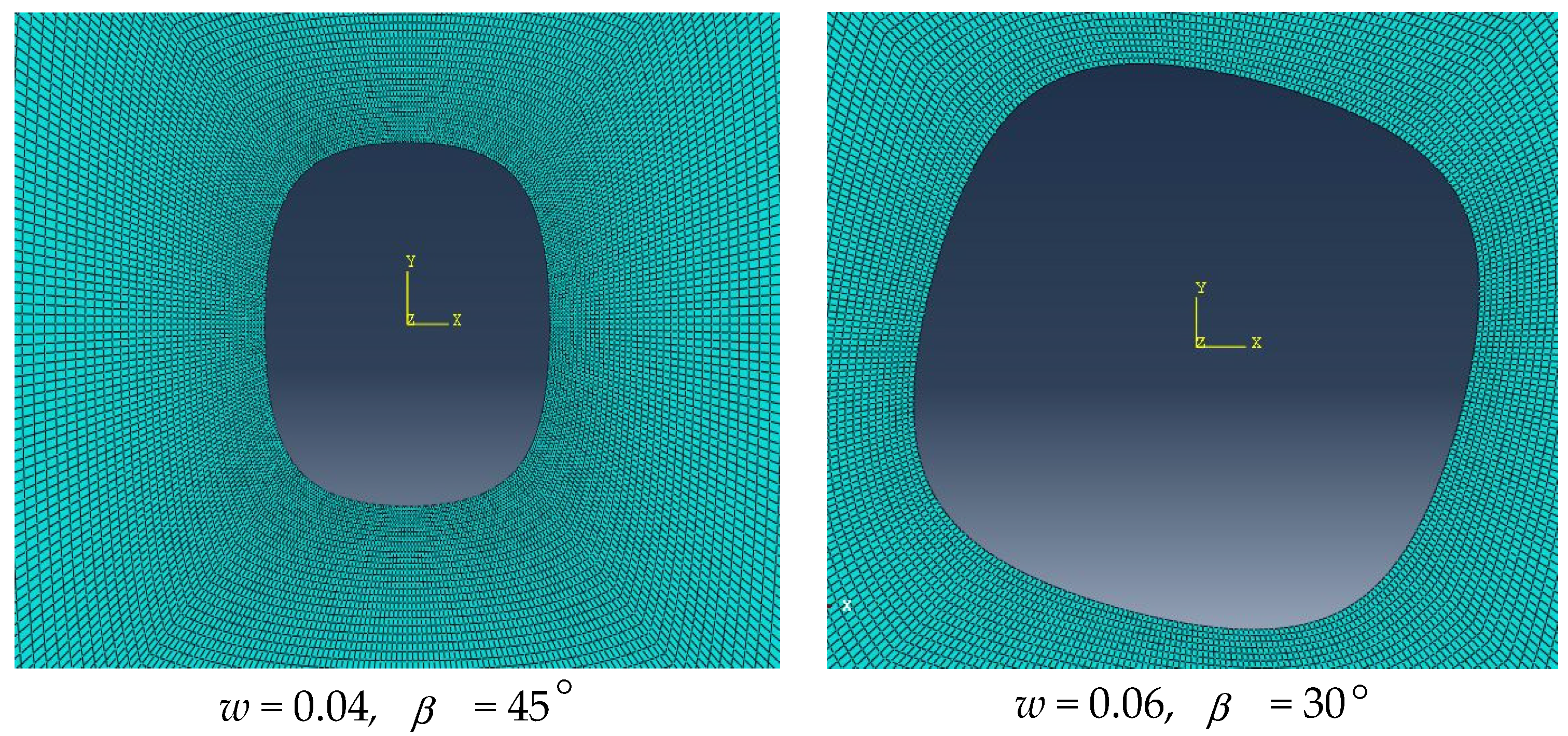
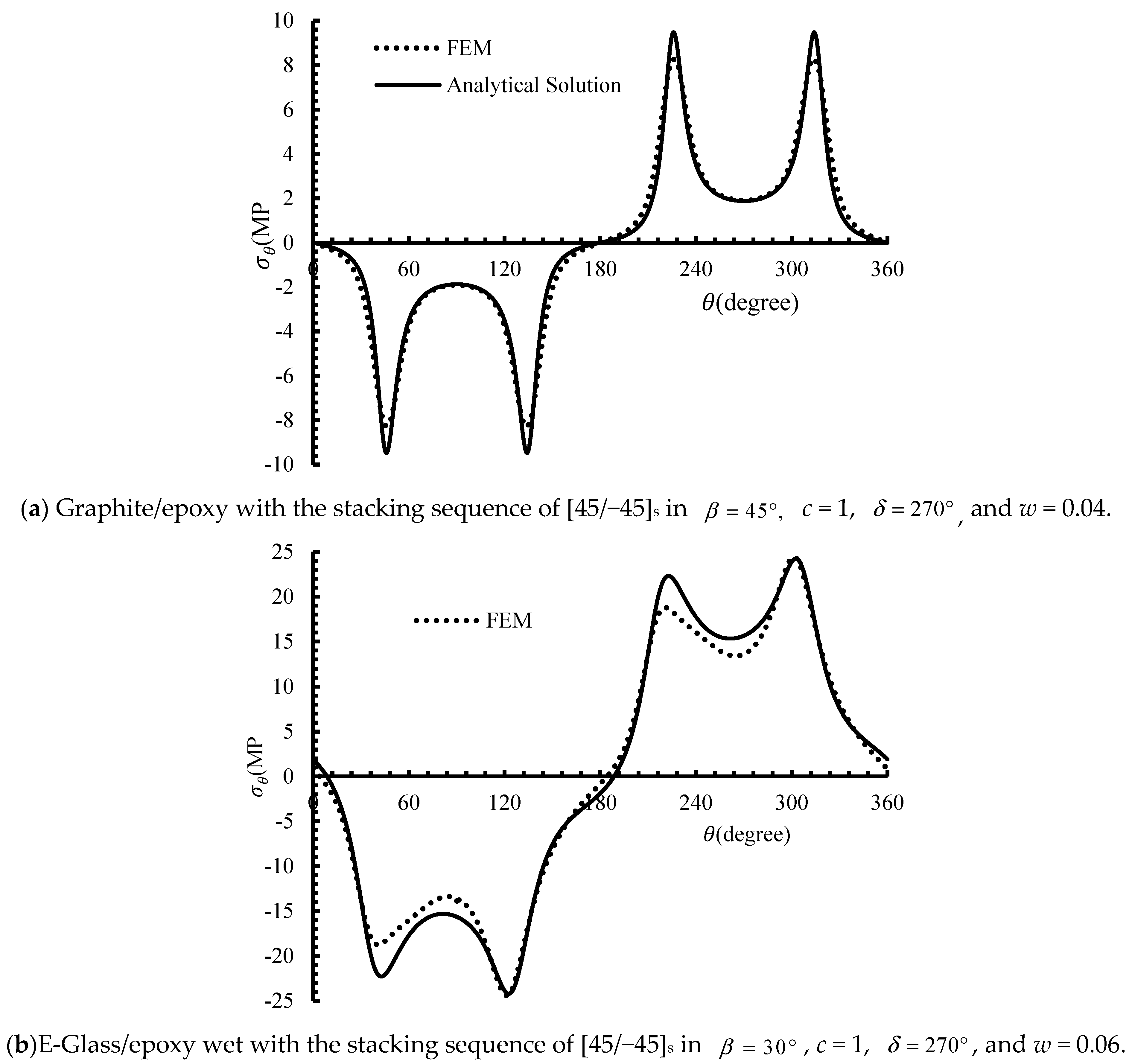
For confirming the analytical results, ABAQUS/standard finite element code is used. The three-dimensional FEM model is used for the numerical analysis of composite laminates weakened by a rectangular hole under uniform heat flux. Four-noded quadrilateral elements are used for modeling composite laminates. To ensure the independence of the numerical results to the element size, a mesh sensitivity analysis is performed. According to Figure 3, the region around the hole is modeled using fine mesh. In this area, the elements number is raised from 40 to 360, and it is observed that the results do not change with further refining of the mesh. Figure 4 compares the analytical and numerical stress distributions ( σ θ ) around the rectangular hole in the multi-layer composite laminates made of graphite/epoxy and E-glass/epoxy wet for the stacking sequence of [45/−45]s. The parameter θ determines the angular position of the edge of the hole relative to the horizontal axis. According to Figure 4, the closeness of the results of the present method and FEM confirms the accuracy of the analytical method.
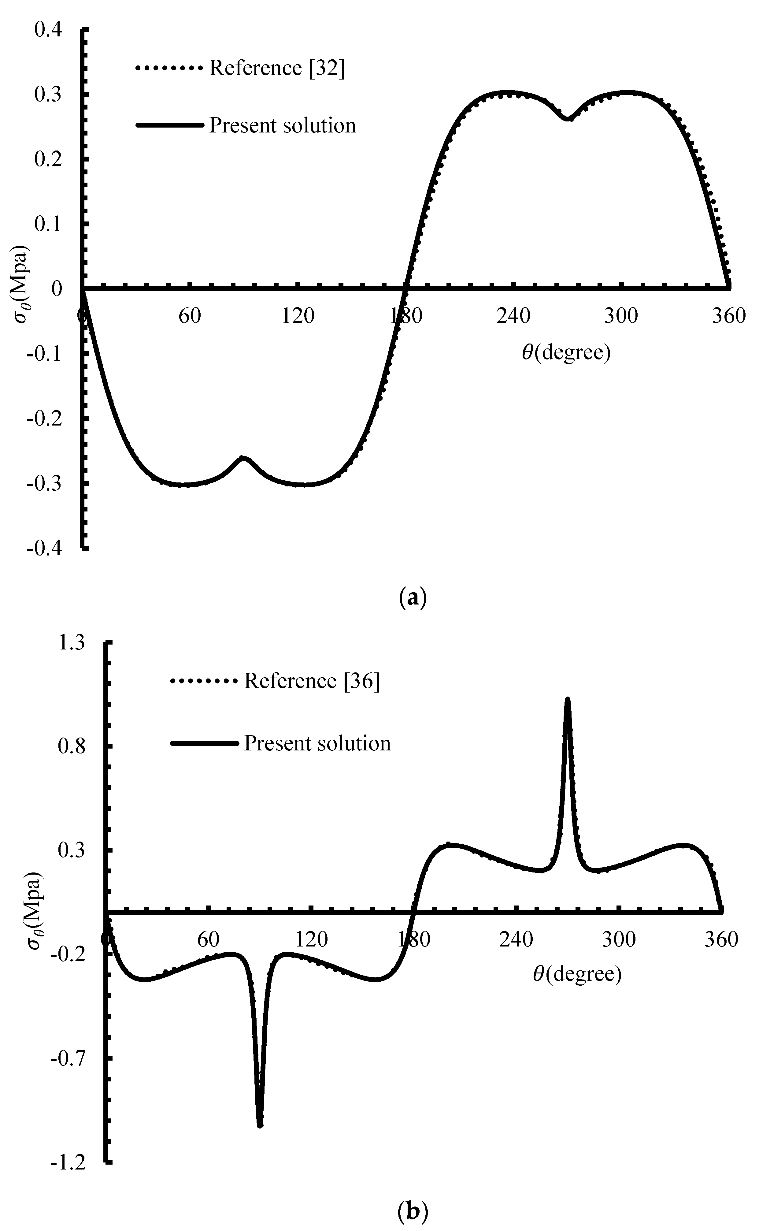
Apart from validating the analytical solution of this study using finite element results, the results obtained by other researchers were used for further validation. Figure 5 compares the results of Rasouli et al. [32] and Jafari et al. [36] with the results obtained using the analytical solution of the current study. In Figure 5a, the stress distribution around a circular hole in an infinite orthotropic single-layer plate under uniform heat flux is presented, and in Figure 5b, the stress distribution around a quasi-square hole in an infinite single-layer orthotropic plate subjected to uniform heat flux is illustrated. Figure 5 shows very good agreement between the results of other researchers with the results of the current analytical solution.

5. Results and Discussion

This section presents the results of interaction of the rotation angle of the hole and heat flux angle on thermal stress distribution surrounding a rectangular hole in the composite laminates made of graphite/epoxy and E-glass/epoxy wet materials under constant heat flux. The maximum normalized thermal stress is defined as σ n o r m = σ θ , max k x A ( 1 , 1 ) q 0 λ | α x | , in which σ θ , max the maximum circumferential stress is induced surrounding the hole. The most important parameters such as the hole orientation angle (β), heat flux angle (δ), bluntness (w), hole aspect ratio (c), and the stacking sequence of [45/−45]s are considered. The maximum and minimum values of stress in this interval are called desirable and undesirable stresses, respectively. It should be noted that the default values of the parameters in Section 5 are δ = 270°, w = 0.05, β = 0°, and c = 1, unless the parameter is varied to study its effect on the thermal stress value. Moreover, the material property of the laminated composite is presented in Table 1.

5.1. Effect of Hole Rotation Angles

The influence of the hole orientation ( β ) on the maximum normalized thermal stress developed around the rectangular hole in laminated composite made of graphite/epoxy and E-glass/epoxy wet with the stacking sequence of [45/−45]s in various values of bluntness is shown in Figure 6. By changing the rotation angle of the hole, the location of the occurrence of the highest normalized stress for each composite laminate also changes. According to Figure 6, the desirable rotation angle for graphite/epoxy composite laminate happens at β = zero, 90°, and 180°, and the undesirable thermal stress occurs at β = 45° and 135°. Whereas, the desirable stress for E-Glass/epoxy wet laminate happens similar to the graphite/epoxy laminate, and the undesirable stress occurs in the range of 35–55° (125–145°) for the stacking sequence of [45/−45]s. Moreover, it is observed that the maximum thermal stress for graphite/epoxy material is equal to 1.58 and that of the E-glass/epoxy wet material is equal to 1.24 when w = 0.07. Therefore, the value of thermal stress is different in both materials, and this value is related to the hole geometric parameters.
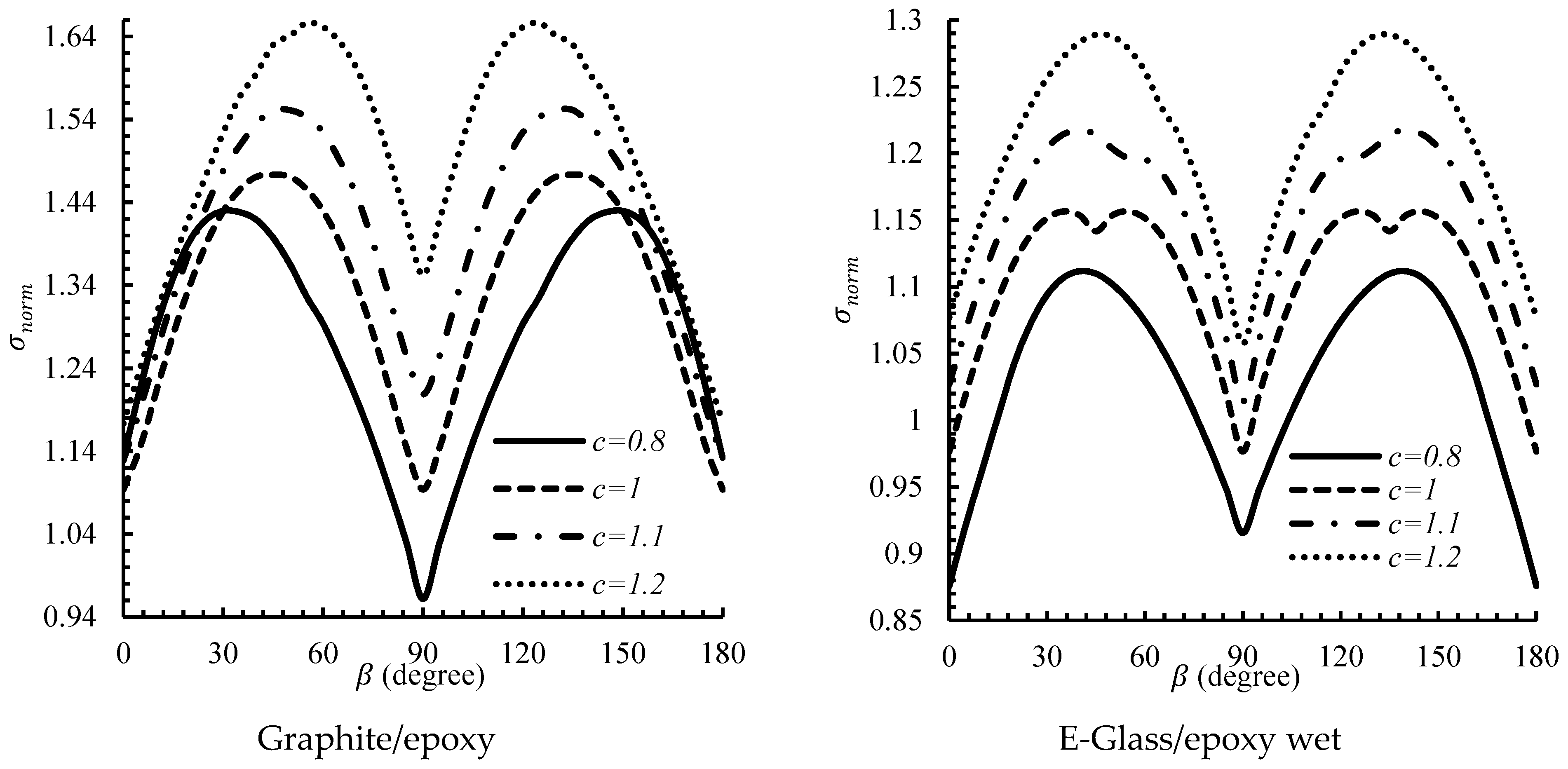
According Figure 7, the thermal stress value increases for two composite materials by increasing the amount of the hole aspect ratio. This is due to the fact that with the increase in the value of c, the hole is elongated in the y-direction, and the shape of the hole is converted from the quasi-square to the rectangular hole with sharper corners. Given that in these cases, the maximum stress occurs at the corners of the hole, as a result, when these areas become sharper, the normalized stress increases at these points. Obviously, by considering the interaction of between the hole orientation and hole aspect ratio for graphite/epoxy material, it can be concluded that the desirable thermal stress is equal to 0.96 when c = 0.8 and β = 90°. Whereas, the desirable thermal stress for E-glass/epoxy wet material is equal to 0.87 when c = 0.8 and β = zero or 90°. As illustrated in Figure 7, for graphite/epoxy and E-glass/epoxy wet materials, the undesirable thermal stresses occurs at c = 1.2 and β = 35° and 135°.
Figure 8 shows the distribution of desirable and undesirable thermal stress around the rectangular hole due to the interaction of hole orientation and heat flux angle. As shown in this figure, by changing the flux angle, the values of stresses also change. If the value of the flux angle is determined, then the lowest normalized stress can be achieved by changing the rotation angle of the hole. According to Figure 8, the desirable thermal stress for graphite/epoxy and E-glass/epoxy wet materials is equal to 1.093 and 0.976 when δ = 0° and β = zero, 90°, and 180°, respectively. The undesirable thermal stress for graphite/epoxy and E-glass/epoxy wet is equal to 2.055 and 1.514 when δ = 45° and β = 45° or 135°, respectively. In the engineering design, the significant factors should be chosen so that the undesirable thermal stress is avoided. So, by selecting the proper value for the hole rotation angle, the thermal stress value can be decreased remarkably.

5.2. Effect of Heat Flux Angle

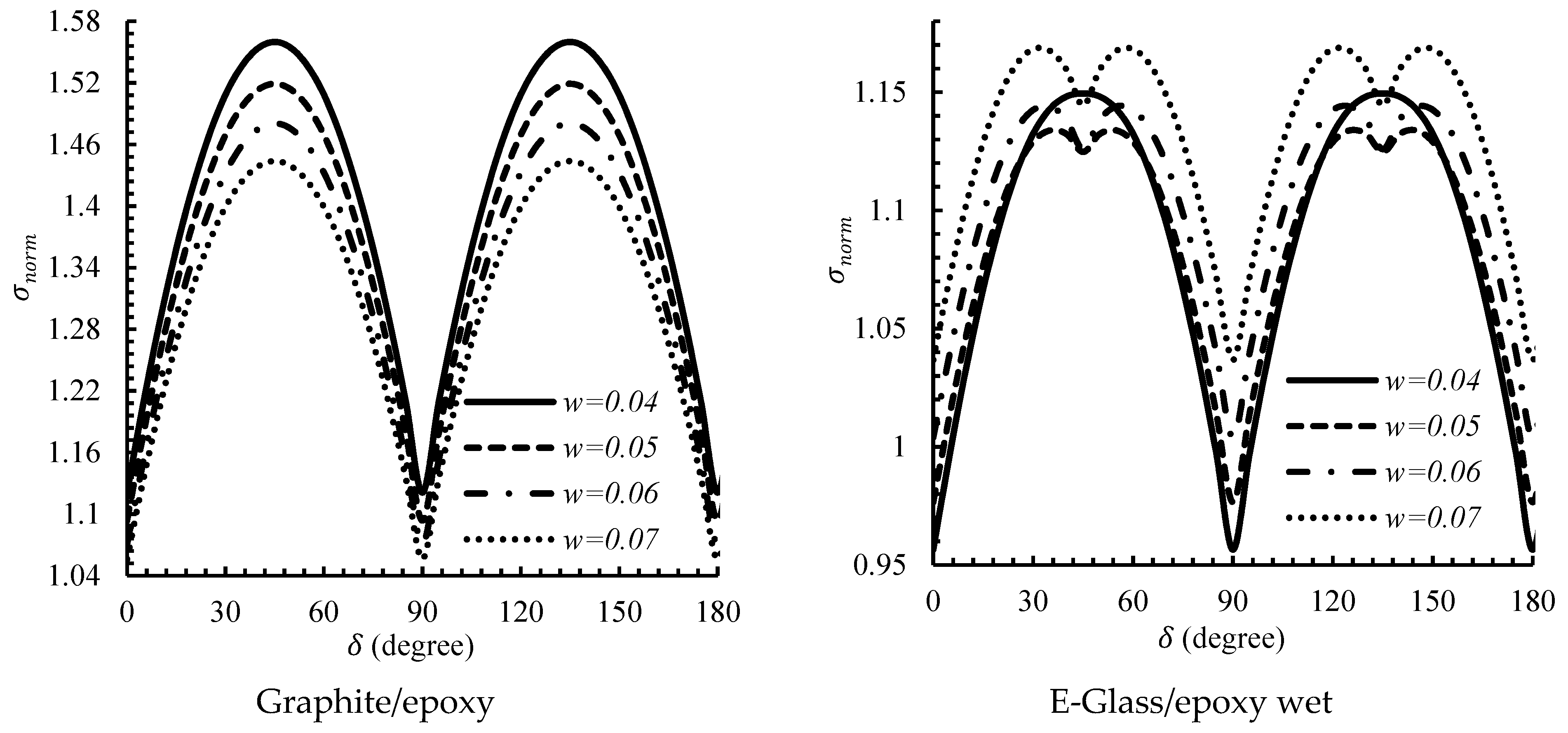
After investigation of the interaction between the rotation angle and other effective parameters and obtaining the values of thermal stress for the rectangular hole, it is necessary to examine the interaction of heat flux angle and the important effective parameters. Then, the values of thermal stress for graphite/epoxy are compared with that of E-glass/epoxy wet in the stacking sequence of [45/−45]s. Figure 9 shows the values of thermal stress in terms of heat flux angle in different values of bluntness (w) parameter. The results show that when the flux angle changes, the location of the maximum normalized stress around the rectangular hole for two composite laminates changes. In other words, in the corners of the hole for the graphite/epoxy composite laminate, if the angle between the normal curve of the boundary of the hole and flux angle is closer to 45° or 135°, the maximum normalized stress will be reduced. Whereas, for E-glass/epoxy wet composite laminate, if the angle between the normal curve of the boundary of the hole and flux angle is closer to zero or 90°, the maximum normalized stress created in these regions increases, and if this angle is closer to 45◦, the maximum normalized stress depends on the hole geometry. According to Figure 9, the desirable thermal stress for graphite/epoxy composite laminate is equal to 1.056 when δ = 90° and w = 0.07, and the undesirable thermal stress is equal to 1.559 when δ = 45° or 135° and w = 0.04. Whereas, the desirable thermal stress for E-glass/epoxy wet composite laminate is equal to 0.956 when δ = 0°, 90°, and 180° and w = 0.04, but the undesirable thermal stress value is depended on the value of bluntness and heat flux angle parameters. However, the undesirable thermal stress in the stacking sequence of [45/−45]s is equal to 1.168 when δ = 35–55° or 125–145° and w = 0.07.
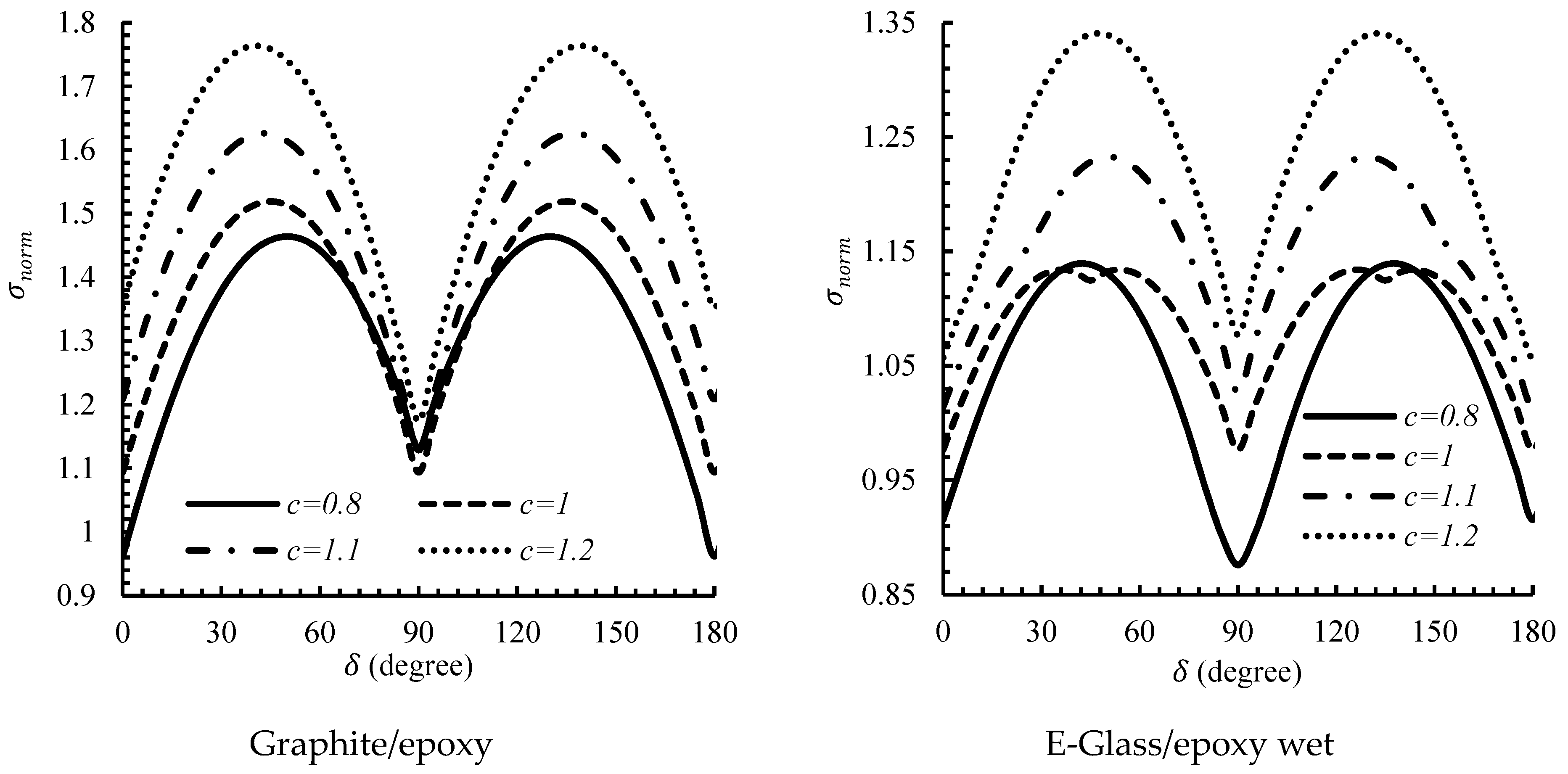
Figure 10 illustrates the effect of heat flux angle on the maximum normalized thermal stress in different values of hole aspect ratio for graphite/epoxy and E-glass/epoxy wet laminates in the stacking sequence of [45/−45]s. As it is clear, the maximum normalized thermal stress of laminate containing a rectangular hole increases with increasing the aspect ratios of the hole.
It is noteworthy that the variation of the normalized stress in terms of heat flux angle illustrates different behavior in different values of the hole aspect ratio. It is observed that the desirable thermal stress for graphite/epoxy is equal to 0.961 when δ = zero or 180° and c = 0.8. In addition, the undesirable thermal stress is equal to 1.763 when δ = 40° or 140° and c = 1.2. According to Figure 10, for E-glass/epoxy wet material, the desirable thermal stress is equal to 0.875 when δ = 90° and c = 0.8 and the undesirable thermal stress is equal to 1.339 when δ = 45° or 135° and c = 1.2.
Finally, the variation of thermal stress distribution in symmetric composite laminate with a rectangular hole in terms of heat flux angle for different hole orientation is shown in Figure 11. According to Figure 11, for graphite/epoxy and E-glass/epoxy wet laminates in the stacking sequence of [45/−45]s, the desirable thermal stress value is obtained at β = 90° and δ = zero, 90°, and 180°. Whereas, the undesirable thermal stress value is obtained at β = 45° and δ = 45°or 135°. It can be seen at different rotation and flux angles that the graphite/epoxy plate has higher thermal stress than the E-glass/epoxy wet plate. Therefore, by selecting the appropriate values of effective parameters, the thermal stress distribution in the symmetric laminated composite containing a hole can be decreased remarkably.

6. Conclusions

An analytical method based on the Lekhnitskii’s complex variable method and a conformal mapping function was employed to study the mutual influence of the mechanical properties and geometric parameters stress distribution surrounding a rectangular hole within a symmetric multilayer composite plate subjected to uniform heat flux. The interaction of the hole angular position, aspect ratio, and bluntness for graphite/epoxy and E-glass/epoxy wet laminate in the stacking sequence of [45/−45]s were investigated on the thermal stress distribution. The results showed that the geometric parameters and material can influence the thermal stresses. According to the results, the hole angular position was found to be an important parameter influencing the thermal stress distribution around the hole. The results showed that the hole angular position of 90° at δ = 0° for the graphite/epoxy plate and hole angular position of 180° at δ = 0° for the E-glass/epoxy wet plate resulted in the minimum stress concentration for the laminate with a stacking sequence of [45/−45]s. Moreover, the desirable thermal stress distribution for the graphite/epoxy plate was obtained for c = 1 at δ = 0° and 180°, and for the E-glass/epoxy wet plate, it was achieved for c = 1 at δ = 90°. So, the heat flux angle and the hole orientation play key roles in obtaining a desirable thermal stress distribution around a rectangular hole. According to the obtained results the graphite/epoxy plate can tolerate higher thermal stress than the E-glass/epoxy wet plate. Unlike the isotropic material, the mechanical properties have a significant effect on the thermal stress distribution. Finite element analyses were employed for validating the analytical solutions. Reasonable agreement was obtained between the finite element and analytical results.

Author Contributions

Writing–review & editing, M.H.B.C., M.J., H.K., E.-M.C. All authors have read and agreed to the published version of the manuscript.

Funding

This research received no external funding.

Conflicts of Interest

The authors declare no conflict of interest.

References

  1. Bitsadze, L. Explicit solution of one boundary value problem of thermoelasticity for a circle with diffusion, microtemperatures, and microconcentrations. Acta Mech. 2020, 231, 3551–3563. [Google Scholar] [CrossRef]
  2. Sarkar, N. Thermoelastic responses of a finite rod due to nonlocal heat conduction. Acta Mech. 2020, 231, 947–955. [Google Scholar] [CrossRef]
  3. Alshaya, A.; Lin, S.J. Hybrid stress analysis of a near-surface circular hole in finite structures. Proc. Inst. Mech. Eng. Part C J. Mech. Eng. Sci. 2019, 234, 1366–1381. [Google Scholar] [CrossRef]
  4. Song, H.P.; Song, K.; Schiavone, P.; Gao, C.F. Design of a neutral elastic inhomogeneity via thermal expansion. Acta Mech. 2020, 231, 2867–2876. [Google Scholar] [CrossRef]
  5. Jafari, M.; Chaleshtari, M.H.B.; Abdolalian, H.; Craciun, E.-M.; Feo, L. Determination of forces and moments per unit length in symmetric exponential FG plates with a quasi-triangular hole. Symmetry 2020, 12, 834. [Google Scholar] [CrossRef]
  6. Wang, X.; Schiavone, P. Uniformity of stresses inside a non-elliptical inhomogeneity near an irregularly shaped hole in plane elasticity. Mech. Mater. 2020, 145, 103389. [Google Scholar] [CrossRef]
  7. Blesa Gracia, J.; Rammerstorfer, F.G. Increase in buckling loads of plates by introduction of cutouts. Acta Mech. 2019, 230, 2873–2889. [Google Scholar] [CrossRef] [Green Version]
  8. Wang, S.R.; Wang, Y.H.; Gong, J.; Wang, Z.L.; Huang, Q.X.; Kong, F.L. Failure mechanism and constitutive relation for an anchorage segment of an anchor cable under pull-out loading. Acta Mech. 2020, 231, 3305–3317. [Google Scholar] [CrossRef]
  9. Jafari, M.; Hoseyni, S.A.M.; Altenbach, H.; Craciun, E.-M. Optimum design of infinite perforated orthotropic and isotropic plates. Mathematics 2020, 8, 569. [Google Scholar] [CrossRef] [Green Version]
  10. Groza, G.; Jianu, M.; Pop, N. Infinitely differentiable functions represented into Newton interpolating series. Carpathian J. Math. 2014, 30, 309–316. [Google Scholar]
  11. Jafari, M.; Bayati Chaleshtari, M.H. Using dragonfly algorithm for optimization of orthotropic infinite plates with a quasi-triangular cut-out. Eur. J. Mech. A/Solids 2017, 66, 1–14. [Google Scholar] [CrossRef]
  12. Lekhnitskii, S.G. Anisotropic Plates, 2nd ed.; Gordon and Breach Science: New York, NY, USA, 1968. [Google Scholar]
  13. Florence, A.L.; Goodier, J.N. Thermal stress at spherical cavities and circular holes in uniform heat flow. J. Appl. Mech. 1959, 26, 293–294. [Google Scholar]
  14. Florence, A.L.; Goodier, J.N. Thermal stresses due to disturbance of uniform heat flow by an insulated ovaloid hole. J. Appl. Mech. 1960, 27, 635–639. [Google Scholar] [CrossRef]
  15. Hasebe, N.; Wang, X. Complex variable method for thermal stress problem. J. Therm. Stresses 2005, 28, 595–648. [Google Scholar] [CrossRef]
  16. Tarn, J.Q.; Wang, Y.M. Thermal stresses in anisotropic bodies with a hole or a rigid inclusion. J. Therm. Stresses 1993, 16, 455–471. [Google Scholar] [CrossRef]
  17. Chao, C.K.; Chang, K.W. Contact stresses in an infinite plate containing a rigid circular inclusion under thermal loads. Acta Mech. 2001, 152, 95–108. [Google Scholar] [CrossRef]
  18. Wang, X.; Dong, M.C.; Lu, G. Thermal elastic-plastic stress analysis of an anisotropic structure. Proc. Inst. Mech. Eng. Part C J. Mech. Eng. Sci. 2003, 217, 723–733. [Google Scholar] [CrossRef]
  19. Ukadgaonker, V.G.; Rao, D.K.N. A general solution for stresses around holes in symmetric laminates under inplane loading. Compos. Struct. 2000, 49, 339–354. [Google Scholar] [CrossRef]
  20. Sharma, D.S. Stresses around polygonal hole in an infinite laminated composite plate. Eur. J. Mech. A/Solids 2015, 54, 44–52. [Google Scholar] [CrossRef]
  21. Goyat, V.; Verma, S.; Garg, R.K. Reduction of stress concentration for a rounded rectangular hole by using a functionally graded material layer. Acta Mech. 2017, 228, 3695–3707. [Google Scholar] [CrossRef]
  22. Dai, M.; Yang, H.-B.; Schiavone, P. Stress concentration around an elliptical hole with surface tension based on the original Gurtin–Murdoch model. Mech. Mater. 2019, 135, 144–148. [Google Scholar] [CrossRef]
  23. Damghani, M.; Harrison, C.; Kennedy, D. The effects of composite laminate stiffness and loading on stress resultant concentration factor around a hole. Proc. Inst. Mech. Eng. Part C J. Mech. Eng. Sci. 2018, 232, 1033–1049. [Google Scholar] [CrossRef]
  24. Choi, H.J. Thermal stresses due to a uniform heat flow disturbed by a pair of offset parallel cracks in an infinite plane with orthotropy. Eur. J. Mech. A/Solids 2017, 63, 1–13. [Google Scholar] [CrossRef]
  25. Xiao, J.; Xu, Y.; Zhang, F. An analytic solution for the problem of two symmetrical edge cracks emanating from a circular hole with surface effect under antiplane shear. Acta Mech. 2018, 229, 4915–4925. [Google Scholar] [CrossRef]
  26. Guo, L.-C.; Noda, N. An analytical method for thermal stresses of a functionally graded material cylindrical shell under a thermal shock. Acta Mech. 2010, 214, 71–78. [Google Scholar] [CrossRef]
  27. Khan, K.A.; Barello, R.; Muliana, A.H.; Lévesque, M. Coupled heat conduction and thermal stress analyses in particulate composites. Mech. Mater. 2011, 43, 608–625. [Google Scholar] [CrossRef]
  28. Zhang, Z.; Demir, K.; Gu, G.X. Computational analysis of thermally induced stress concentration in structures with geometric constraints. Mech. Mater. 2019, 133, 102–110. [Google Scholar] [CrossRef]
  29. Li, L.; Jia, P.; Pan, W. Temperature effect on the tensile behaviors of carbon/polyimide composite laminate. Proc. Inst. Mech. Eng. Part C J. Mech. Eng. Sci. 2016, 231, 4592–4602. [Google Scholar] [CrossRef]
  30. Mahmoudi, H.; Atefi, G. Analytical solution for thermal stresses in a hollow cylinder under periodic thermal loading. Proc. Inst. Mech. Eng. Part C J. Mech. Eng. Sci. 2011, 226, 1705–1724. [Google Scholar] [CrossRef]
  31. Jafari, M.; Nazari, M.B.; Taherinasab, A. Thermal stress analysis in metallic plates with a non-circular hole subjected to uniform heat flux. Eur. J. Mech. A/Solids 2016, 59, 356–363. [Google Scholar] [CrossRef]
  32. Jafari, M.; Bagher Nazari, M.; Taheri Nasab, A. Study of the effective parameters on stress distribution around triangular hole in metallic plates subjected to uniform heat flux. J. Therm. Stresses 2016, 39, 333–344. [Google Scholar] [CrossRef]
  33. Rasouli, M.; Jafari, M. Thermal stress analysis of infinite anisotropic plate with elliptical hole under uniform heat flux. J. Therm. Stresses 2016, 39, 1341–1355. [Google Scholar] [CrossRef]
  34. Chao, C.K.; Chen, F.M.; Lin, T.H. Thermal stresses induced by a remote uniform heat flow interacting with two circular inclusions. J. Therm. Stresses 2017, 40, 564–582. [Google Scholar] [CrossRef]
  35. Chao, C.-K.; Gao, B. Mixed boundary-value problems of two-dimensional anisotropic thermoelasticity with elliptic boundaries. Int. J. Solids Struct. 2001, 38, 5975–5994. [Google Scholar] [CrossRef]
  36. Chiang, C.-R. Thermal stress at a circular hole in cubic crystals under uniform heat flow. Acta Mech. 2018, 229, 3963–3969. [Google Scholar] [CrossRef]
  37. Jafari, M.; Jafari, M. Thermal stress analysis of orthotropic plate containing a rectangular hole using complex variable method. Eur. J. Mech. A/Solids 2019, 73, 212–223. [Google Scholar] [CrossRef]
  38. Jafari, M.; Jafari, M. Effect of hole geometry on the thermal stress analysis of perforated composite plate under uniform heat flux. J. Compos. Mater. 2018, 53, 1079–1095. [Google Scholar] [CrossRef]
  39. Hahn, D.W.; Özişik, M.N. Heat Conduction Fundamentals. In Heat Conduction, 3rd ed.; John Wiley & Sons, Inc.: Hoboken, NJ, USA, 2012; pp. 1–39. [Google Scholar]
Figure 1. Symmetric composite laminated containing a rectangular hole subjected to steady heat flux [37].
Mathematics 09 00311 g001
Figure 2. Effect of w on the rectangular hole shape.
Mathematics 09 00311 g002
Figure 3. Mesh refinement for composite laminate containing rectangular hole.
Mathematics 09 00311 g003
Figure 4. FEM and analytic solution comparison for different composite materials in various stacking sequence.
Mathematics 09 00311 g004
Figure 5. Comparison between the present solution and other researchers’ results, (a) Ref. [32], (b) Ref. [36].
Mathematics 09 00311 g005
Figure 6. Effect of hole orientation on the maximum normalized stress in different values of w.
Mathematics 09 00311 g006
Figure 7. Effect of hole rotation angle on the maximum normalized stress in different values of c.
Mathematics 09 00311 g007
Figure 8. Effect of hole rotation angle on the maximum normalized stress in different values of δ .
Mathematics 09 00311 g008
Figure 9. Effect of heat flux angle on the maximum normalized stress in different values of w.
Mathematics 09 00311 g009
Figure 10. Effect of heat flux angle on the maximum normalized stress in different values of c.
Mathematics 09 00311 g010
Figure 11. Effect of heat flux angle on the maximum normalized stress in different values of β .
Mathematics 09 00311 g011
Table 1. Mechanical properties of the studied materials [33].
MaterialE11 (GPa)E22 (GPa)G12 (GPa)υ12α11 (K−1)α22 (K−1)K11 (Wm−1 K−1)K22 (Wm−1 K−1)
Graphite/epoxy144.89.74.10.3−3 × 10−62.8 × 10−54.620.72
E-Glass/epoxy wet3594.70.285.5 × 10−62.5 × 10−52.21.1
E 33 = E 22 ,   G 12 = G 13 = G 23 , υ 12 = υ 13 = υ 23 ,   α 33 = α 22 , K 33 = K 22 ,   K 12 = 0
Publisher’s Note: MDPI stays neutral with regard to jurisdictional claims in published maps and institutional affiliations.