Review

Enhancing Gain for UWB Antennas Using FSS: A Systematic Review

by
Ahmed Jamal Abdullah Al-Gburi
1,
Imran Mohd Ibrahim
1,*,
Zahriladha Zakaria
1,*,
Muhannad Kaml Abdulhameed
2 and
Tale Saeidi
3
1
Department of Electronics and Computer Engineering (FKEKK), Center for Telecommunication Research and Innovation (CeTRI), Universiti Teknikal Malaysia Melaka (UTeM), Durian Tungal 76100, Malaysia
2
Information Technology Department, University of Kerbala, Karbala 56001, Iraq
3
Electrical and Electronics Engineering Department, Universiti Teknologi Petronas (UTP), Perak 32610, Malaysia
*
Authors to whom correspondence should be addressed.
Mathematics 2021, 9(24), 3301; https://doi.org/10.3390/math9243301
Submission received: 25 October 2021 / Revised: 13 December 2021 / Accepted: 15 December 2021 / Published: 18 December 2021
(This article belongs to the Special Issue Evolutionary Optimization Algorithms for Electromagnetic Devices)

Abstract

:
This review paper combs through reports that have enhanced antenna gain for ultra-wideband (UWB) frequencies using frequency-selective surface (FSS) techniques. The FSS techniques found across the research landscape were mapped onto a taxonomy in order to determine the most effective method for improving antenna gain. Additionally, this study looked into the motivation behind using FSS as a reflector in UWB frequencies to obtain directional radiation. The FSS suits multiple applications due to its exceptional ability to minimize power loss in undesired transmission areas in the antenna, as well as to hinder the interference that may occur from undesirable and wasted radiation. An efficient way to obtain constant gain over a wide range of frequencies is also elaborated in this paper. Essentially, this paper offers viable prescription to enhance antenna gain for UWB applications. Methods: A comprehensive study was performed using several imminent keywords, such as “high gain using FSS”, “gain enhancement using FSS”, “high gain UWB antennas”, and “gain enhancement of UWB antennas”, in different modifications to retrieve all related articles from three primary engines: Web of Science (WoS), IEEE Xplore, and Science Direct. Results: The 41 papers identified after a comprehensive literature review were classified into two categories. The FSS single- and multi-layer reflectors were reported in 25 and 16 papers, respectively. New direction: An effective method is proposed for FSS miniaturization and for obtaining constant gain over UWB frequencies while maintaining the return loss at −10 dB. Conclusion: The use of FSS is indeed effective and viable for gain enhancement in UWB antennas. This systematic review unravels a vast range of opportunities for researchers to bridge the identified gaps.

1. Introduction

Improvements in periodic formations reflect the growth of two-dimensional surfaces with other periodic components that enable them to act as a perfect magnetic conductor (PMC), along with the reflection scattering in a narrow bandwidth (BW) [1,2]. The inclusion of such periodic structures improves impedance matching, which, in turn, increases the efficiency of some antennas, including UWB planar antennas, when they are placed near metallic surfaces to deliver unidirectional radiation. These periodic arrangements denote a combination of FSS and conventional metallic reflectors [3,4]. The FSS, which is applied to address several critical issues across multiple research fields, has been introduced as a UWB reflector [5]. Notably, the FSS is keeping up with the evolving demands for more extensive BW not only for telecommunication purposes, but also for other advanced applications that heavily rely on certain BW to perform, thus leading to a global hunt for new technologies that conveniently generate unique signals occupying a wide range of frequencies. As a result, the concept of UWB was initiated and several worldwide organizations have introduced sets of governmental commands for coordinated use of this sophisticated technology [6]. Antennas are essential components of wireless transmission systems. Fractal antennas have been proposed to obtain resonance compression and multi-band behavior that has been initially assigned to the space-filling characteristics of the fractal geometry [7,8,9]. Nowadays, there is a huge demand for small antennas for mobile communication systems [10,11]. To solve the difficulty in the wide frequency range, the use of artificial dielectrics and magnetic materials has been proposed, such as metamaterials (MTMs) [12]. They have been used in conventional ones as the surrounding environment. The dielectric substrates and ground planes were used to structure the antennas, filters, and polarizer devices. The MTMs are used as a power absorber of electromagnetic waves (EMWs) to eliminate the unwanted frequency (with the same concept of using FSS), which can cause undesired EMW coupling in radar applications [13]. Both the design and analysis of UWB and fractal antennas are more challenging than conventional narrowband antennas because the performance of the latter antennas is estimated at the central frequency [14,15,16] while the behavior of the former antennas must be understood and no distortion should be present over the whole wide operating band. Studies on UWB planar antennas have mostly focused on the omnidirectional antenna, primarily because omnidirectional radiation can cover almost all areas of the device [17,18,19] and suits mobile telecommunication applications. Nevertheless, unidirectional radiation is more attractive due to its ability in reducing power loss, hence avoiding the interference that can result from unwanted and unused radiation.
Properly designed and developed UWB FSS reflectors can generate unidirectional radiation with UWB multidirectional radiation antennas. Besides, it facilitates and shields them from nearby metallic surfaces that may damage the performance of the UWB antennas, thus affording them angular suitability for UWB applications [20,21]. Many techniques have been proposed using FSS to enhance the gain for UWB planar antennas, including single- and multi-layer [22,23] configurations.
In order to assess and benchmark gain enhancement classification methods that can be applied in the detection of the UWB planar antenna, many requirements have been proposed to ensure the authenticity of these methods, given that they are related to enhanced antenna performance. Essentially, two main questions that rose from these procedures are as follows: first, what are the relevant criteria that should be met in the evaluation? Second, what is the proper benchmark method that can be used to identify the most appropriate technique for enhancing gain in UWB planar antennas using FSS?
The critical contribution of this review paper is listed in the following:
  • To the best of the authors’ knowledge, this is the first review article that looks into the ability of FSS to enhance and stabilize the gain for UWB antennas with a new direction to provide FSS miniaturization.
  • Systematically reviews the development of gain enhancement techniques using FSS as a reflector for UWB applications.
  • Maps associated studies into a comprehensible taxonomy, apart from highlighting the methods, theories, and enhancement analysis models used.
  • The benefits and drawbacks of numerous research structures on both conventional and advanced gain improvement methods are marked with many articles’ references to provide a clear picture for interested researchers to further prod into the design of UWB planar antennas.

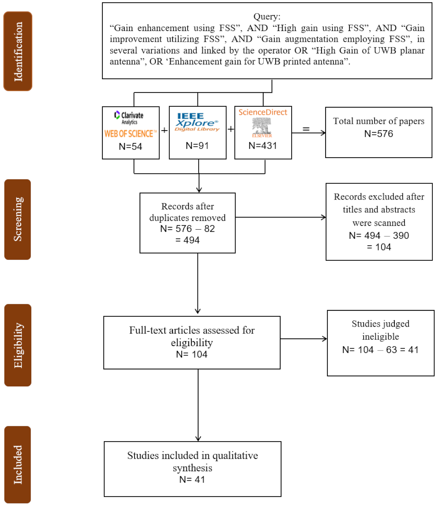
2. Systematic Literature Review Characterization and Queries

The most relevant keywords in the assessed field are “FSS”, “gain enhancement”, and “UWB planar antennas”. In search for gain enhancement, “millimeter-wave applications” (e.g., for non-planar antennas, such as helical and parabolic antennas) were omitted. This study only focused on articles that assessed planar antennas with UWB applications reported in the English language.
The systematic review in this study was executed by deploying the Preferred Reporting Items for Systematic reviews and Meta-Analysis (PRISMA) [24,25,26,27,28,29,30]. The three search engines that were combed through in the search for relevant articles are as follows: first, IEEE Xplore is an academic research engine that offers accessibility to more than five million full-text documents from some of the world’s most highly-cited publications in electrical engineering, computer science, and electronics. Second, WoS provides a subscription-based accessibility to various databases that present comprehensive citation for different educational disciplines, including science, social science, arts, and humanities. It was initially developed by the Institute for Scientific Information and is currently managed by Clarivate Analytics. The third and last search engine refers to ScienceDirect, which is a website that provides access to an extensive bibliographic database of scientific and medical publications of the British publisher Elsevier. These three databases are sufficient to cover studies related to FSS and gain enhancement for UWB planar antennas. The search engines enable an in-depth comprehensive review within the discipline scope.
After retrieving the relevant articles for literature references, three phases of viewing and filtering were executed. In the first phase, all irrelevant papers were discarded. Next, in the second phase, duplicates and unnecessary documents were removed by going through the titles and abstracts of the articles. In the final phase, the full-text papers derived from the second phase were accurately selected based on the qualification criteria set in this present study.
The search for relevant articles was carried out in March 2021 from the three selected search engines; IEEE Xplore, ScienceDirect, and WoS. In order to distinguish the subjects associated with the studied field, a query containing the following various keywords was executed: “gain enhancement using FSS”, “high gain using FSS”, “gain improvement utilizing FSS”, and “gain augmentation employing FSS”, in several variations and linked by the operator ‘OR’, as well as “ultrawideband planar antenna”, “ultrawide-band planar antenna”, “UWB planar antenna”, and “UWB printed antenna” in various variations and connected by the operator ‘AND’. Figure 1 illustrates the query process.
High-level search preferences in the search engines were utilized to eliminate book chapters, letters, and reports while simultaneously improving access to up-to-date scientific papers revolving around planar antennas for UWB applications. Table 1 lists the frameworks used to operate the search engine query.
The initial search produced 576 articles published from 2011 to 2021 (54, 431, and 91 papers retrieved from WoS, Science Direct, and IEEE Xplore, respectively). Next, 82 duplicate articles were discarded, thus leaving 494 articles. After analyzing the article titles and abstracts, 390 articles were eliminated and only 104 articles were retained for further analysis. The remaining 104 full-text articles were further filtered and resulted in 41 viable articles for this study purpose. These 41 selected articles were read carefully to produce a complete outline of the study objective. Each paper that met the qualification criteria listed in Figure 1 was retained for further analysis. The classes were obtained from a pre-survey of the research literature. After the primary removal process of duplicates, the remaining papers were eliminated based on two categories of screening and filtering upon failing to satisfy the fixed criteria. The exclusion criteria were formed based on two steps: (1) non-English articles and (2) topics that stray from gain enhancement for UWB planar antennas.

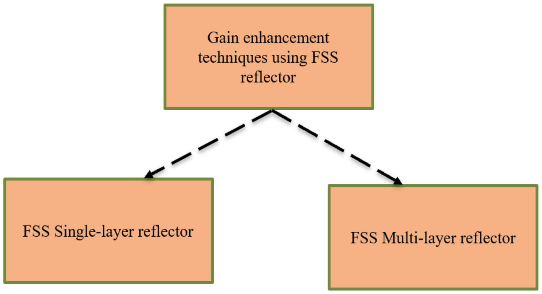
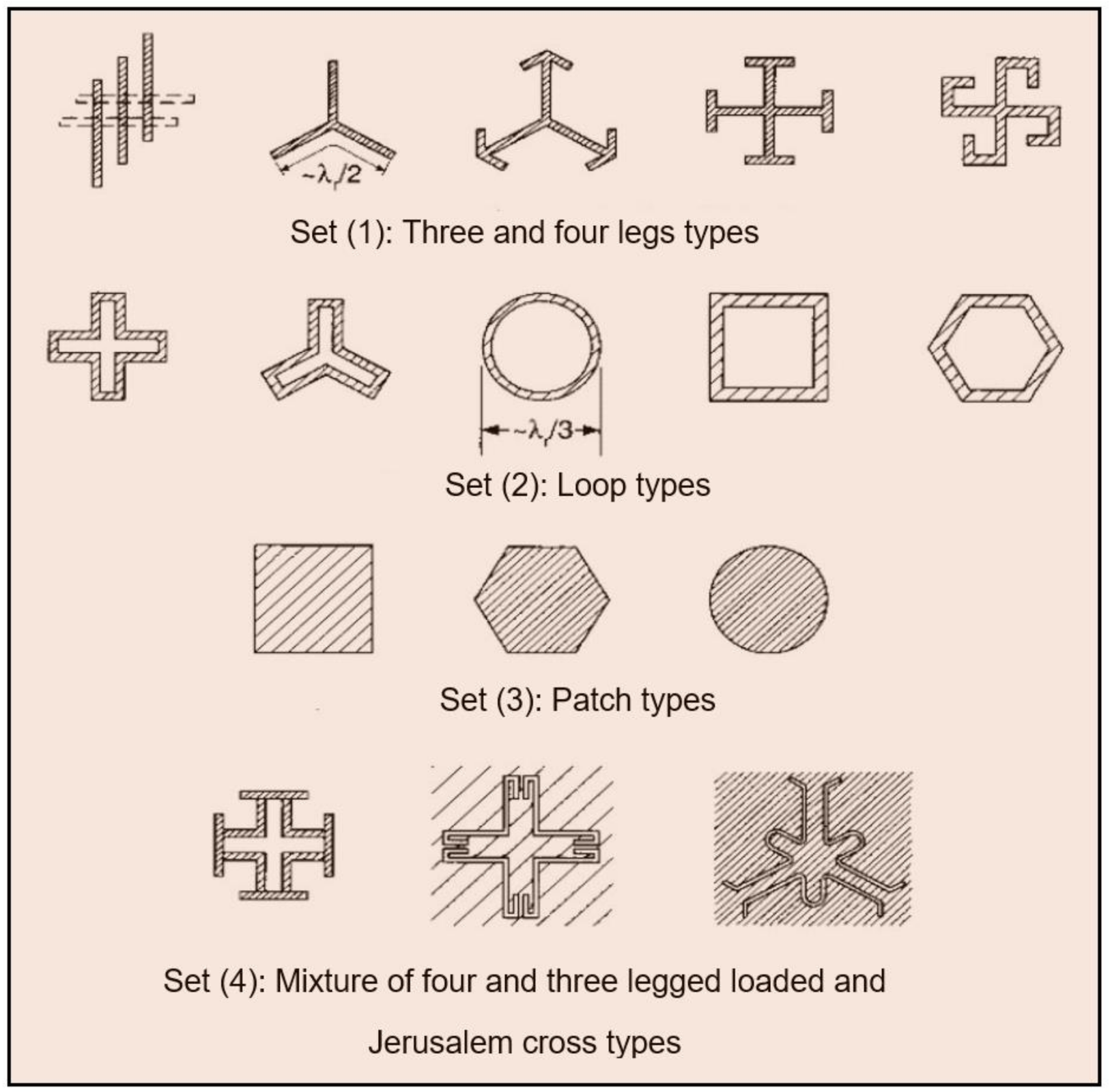
3. Literature Taxonomy on Gain Enhancement Techniques Using FSS

This study introduces a general taxonomy for the gain enhancement techniques applied for UWB planar antennas using FSS reflectors based on two groups. All the carefully selected articles via the systematic literature review were read, digested, and saved in a Microsoft Excel Worksheet. The grouping of every document was based on the structure of the deductive taxonomy. The final articles were classified into two groups: (1) FSS single-layer reflectors (n = 25, 60.9%) and (2) FSS multi-layer reflectors (n = 16, 39%). Besides revealing the patterns, the taxonomy analysis outcomes identified the general and sub-categories. Figure 2 shows the research taxonomy of gain enhancement techniques using FSS reflectors.

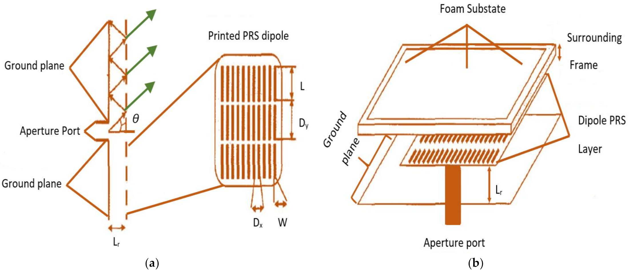
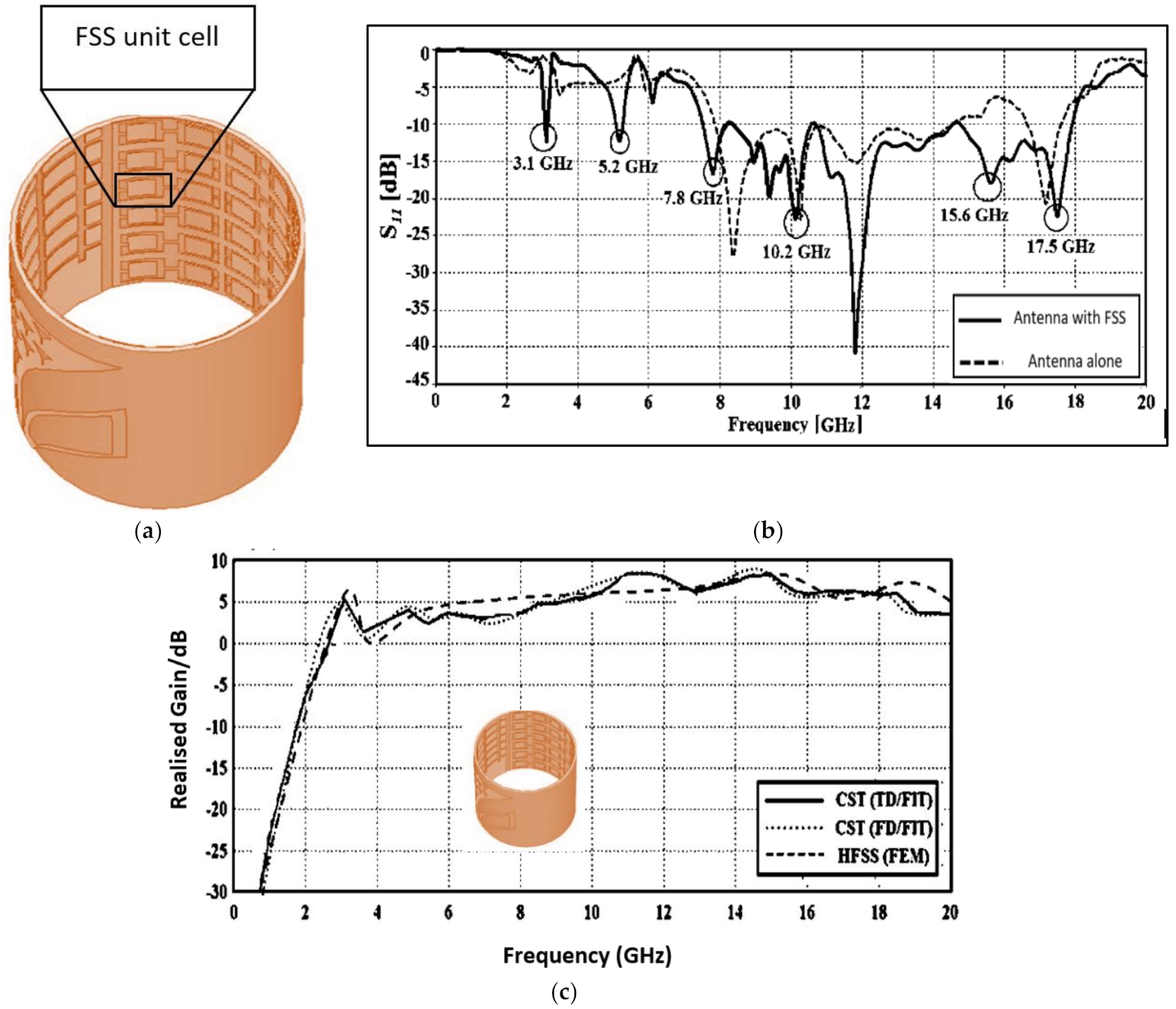
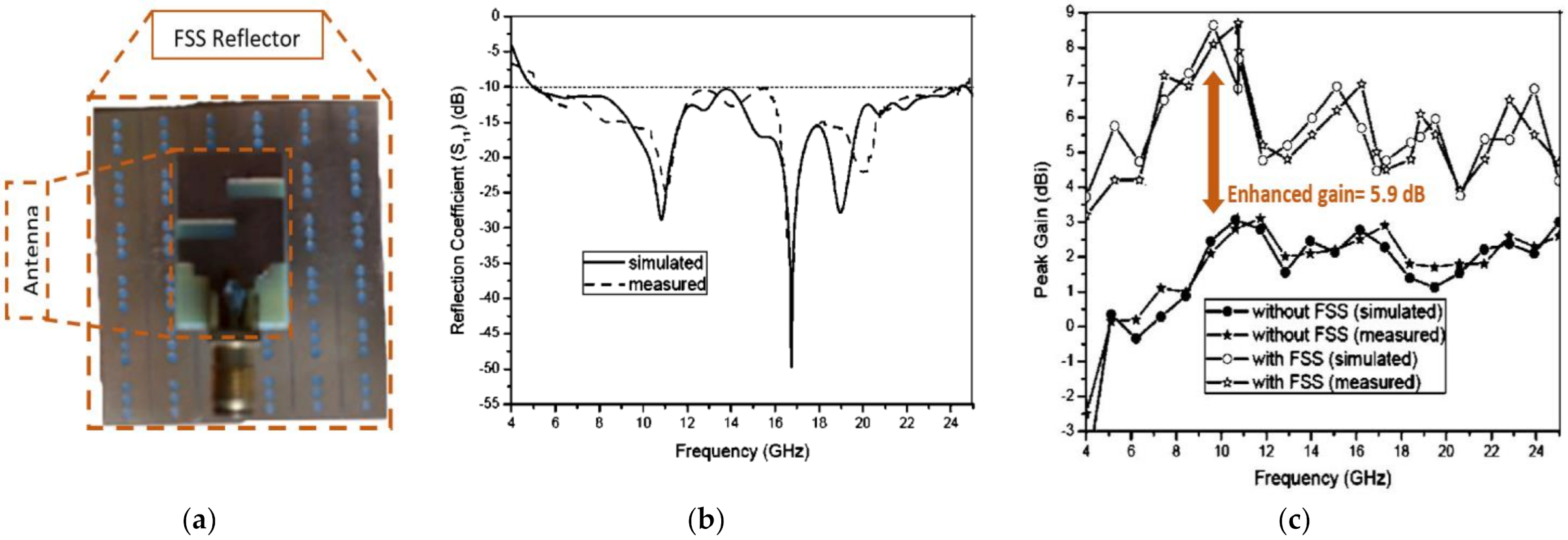
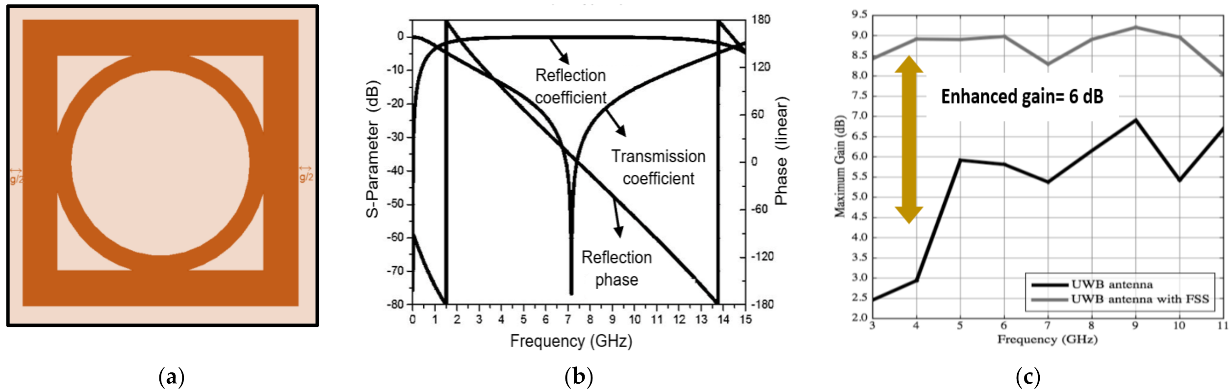
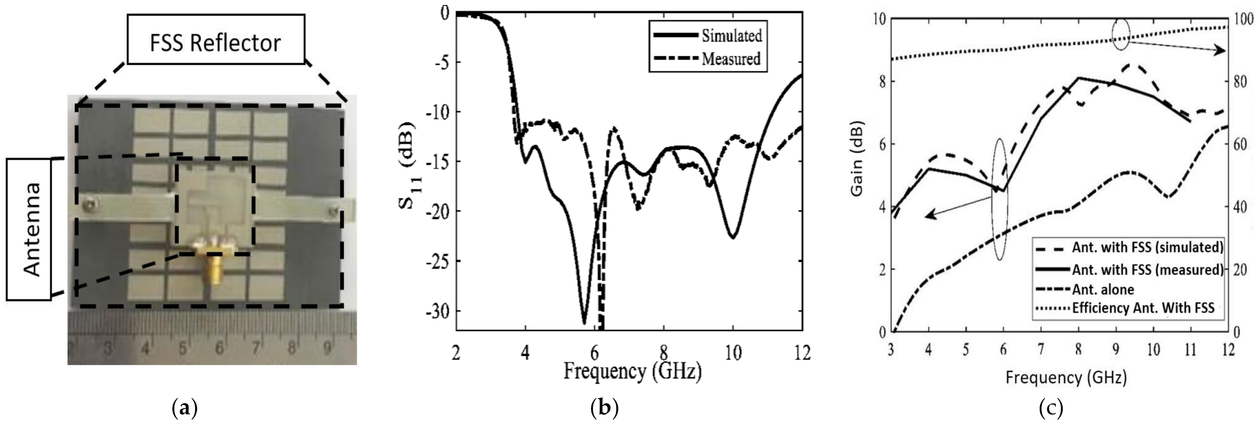
3.1. FSS Single-Layer Reflectors

The possibility of FSS and its ability to enhance the gain for UWB antennas have been clearly analyzed and discussed in this study. The concept of using the FSS single layer as a reflector is similar to the concept of a partially reflecting surface (PRS) [31,32,33] that allows some frequencies to pass through when serving as a passband filter but reflects other frequencies when serving as a stopband. The theoretical explanation is presented in the next section. The structure of UWB planar antennas matches the Fabry–Perot interferometer principle [34,35], whereby the reflected waves from the antennas are now followed by highly reflective PRS with a metallic ground plane that turns them into fully reflective surfaces. By assuming a free-standing array in proximity to an all-metal ground plane illuminated by a normally incident wave, the array resonance can be defined at the frequency where the currents excited on the array are in phase with the incident wave. At this frequency, the incident wave is reflected from the periodic array with phase reverse, as in the case of the free-standing array resonance. However, it can be found that there a Fabry–Perot type of resonance also occurs at the cavity formed between the ground plane and the array. The Fabry–Perot resonance occurs at frequencies different from the array resonance. This strong cavity-type resonance excites maximum currents on the elements (which in general are out of phase with the incident wave), and the incident wave is reflected with a zero-phase magnitude. The reflection properties of PRS change over frequency. Therefore, the frequency is independent of the partially metallized in the presence of the ground plane using the Fabry–Perot interferometer. The schematic description of a UWB planar antenna using PRS is displayed in Figure 3. An open-ended rectangular waveguide, embedded within the ground plane, is used as the primary antenna as it is simple and has an adequate bandwidth. The antenna function can be defined and presented as follows. Waves emerging from the direct antenna travel long routes due to multiple reflections between the ground plane and the PRS. A phase shift is introduced by the route length, the total reflection on the ground plane, and the phase of the reflection coefficient of the PRS. The transmitted power can be determined by the interference of the ongoing waves partially transmitted by the PRS. The total of the transmitted waves produces an analytic equation for the power pattern, given by [36]:
P   θ   = 1 R 2   θ 1 R 2   θ 2 R θ   C O S   Φ θ π 4 π L r λ o   F 2   θ
where R(θ) is the complex reflection coefficient of the PRS as a function of θ, λo is the free-space wavelength, and F(θ) is the radiation pattern of the primary antenna.
The resonant distance between FSS and ground is denoted as Lr. The highest power is taken at broadside, as expressed in the following equation:
  L r = φ θ π 1 λ o 4 + N λ o 2
where: N = 0, 1, 2, …;
φ θ : reflection coefficient;
λ o : wavelength at a specific frequency.
The FSS with a ground plane of unlimited sizes was considered. The explanation for the broadside gain related to the antenna can be calculated by determining the magnitude of the reflection coefficient:
G = P F = 1 + R 1 R
where R is the complex reflection coefficient.
The uncomplicated method proposed here for BW, determined for highly reflecting periodic over free reflection properties, is as follows:
B W = Δ f 1 / 2 f o = λ 2 π L r 1 R R  
The rise in gain relies on R, as denoted in Equation (3). High gain may be achieved with a fully reflective surface (using the FSS reflector). However, BW decreases as R rises, as expressed in Equation (4). However, a narrow BW is required upon an increment in the gain. As N gets higher, the side-lobe effects become stronger as well. Nonetheless, it is imminent to maintain a wideband while achieving high gain. One method to improve both gain and BW at a resonant frequency is to control the reflection properties (magnitude and phase) of PRS by applying Equation (2) and Equation (3), in [36]. The resonant distance (Lr) is key for the running frequency and the reflection coefficient of the PRS sheet. It has a constant value for a distinct running frequency of the radiator. Readjusting the phase position in Equation (1) reveals that in order for a peak to achieve gain in a particular frequency spectrum, the phase value of the reflection coefficient of the PRS must meet the following formula:
φ θ = 4 π L r C = f 2 N 1 π  
Therefore, a linear decline over the frequency phase response will result in a maximum gain within a specific frequency range. The peak gain will be calculated from the magnitude of the reflection coefficient, which should ideally be constant, as shown in Equation (3). Under these two conditions, a high gain and wide bandwidth can be achieved.
Many researchers have used FSS array unit cells as a reflector by printing it on a dielectric substrate on one side of the sheet to enhance the gain over UWB frequencies with varying enhancements. An FSS array textiles reflector, along with a UWB patch antenna, was proposed to enhance gain over the UWB spectrum for wearable communication systems [37,38,39]. In another study, a square FSS exhibited a fractional BW of 22.4% and released a high gain of 6.0 dB [37]. The antenna with the FSS reflector is portrayed in Figure 4.
Some FSSs were designed based on metallic reflectors to improve gain with bidirectional radiation of planar antennas [40,41,42,43,44,45]. Meanwhile, gain was enhanced from 2.2 to 6.4 dB while keeping the UWB BW below −10 dB (see Figure 5) [40]. Another study proposed a total antenna dimension of 52.8 mm × 52.8 mm × 1.6 mm for gain enhancement application [45]. The proposed antenna yielded a fractional BW of 132% for frequencies ranging from 5.0–24.5 GHz (see Figure 6). However, these metallic reflectors cannot stabilize the gain over a wide range of frequencies due to the out phase of their reflections. Besides, achieving steady gain over a wide range of frequencies is crucial for many applications.
Several pioneering FSS single-layer reflectors have been proposed to enhance the gain of UWB planar antennas based on the magnitude of their phase reflections [46,47,48,49,50,51,52,53,54,55,56,57,58,59,60,61,62,63,64,65,66,67], signifying that the separation between the antenna and reflector is imminent in gain improvement techniques. Gain was enhanced when the reflector was placed at a distance of 49.6 mm, along with a reasonable return loss performance [46].
Meanwhile, at a gap of 17.6 mm, the antenna peak gain increased to 8.95 dB [47]. At a 15 mm distance, the gain was recorded at 3.5 dB [48] while 3.74 dB [49] and a comfortable response of 5.0 dB for gain variation [50]. The principal requirements to attain high gain with minor variation enhancement for the UWB spectrum must be fulfilled to guarantee the highest efficiency, such as specified reflection loss and a lower reflection phase, which are rather difficult to achieve in the presence of interference. However, these demands can be met during the linearly falling phase at a certain frequency [51,52,53,54,55,56]. A steady gain can be achieved when the reflection magnitude of the FSS unit cell linearly declines with the band [54,55], whereby a constant gain with 1.8 dB of variation was reported for frequencies at 3–12 GHz (see Figure 7).
Recently, FSS was deployed to enhance the performance of UWB antennas and to obtain high gain by using a circular polarized (CP) antenna [56,57,58,59,60]. A single FSS layer was proposed with the CP antenna to improve both the CP characteristics and antenna gain [57]. The finalized FSS yielded a BW from 3.7 to 11.1 GHz with a peak gain of 9.4 dB and 84% of efficiency at 9.2 GHz (see Figure 8).

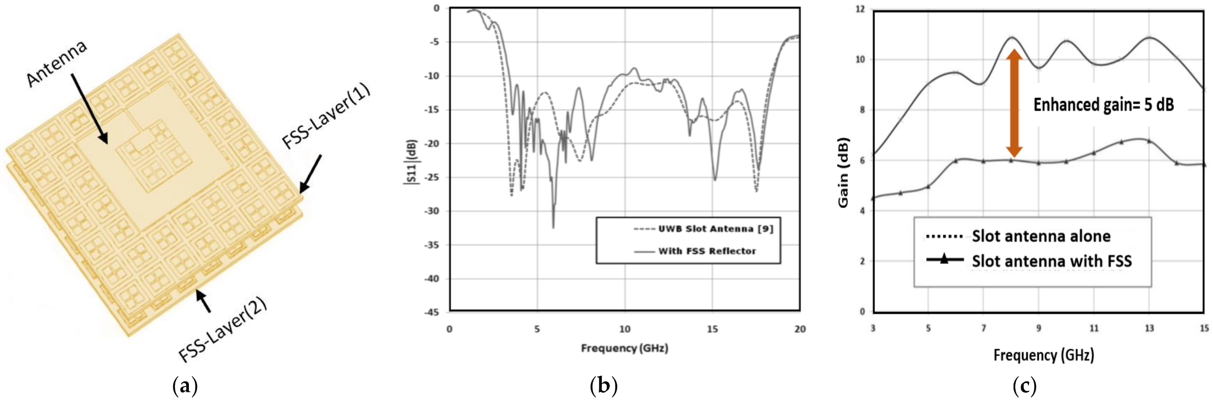
3.2. FSS Multi-Layer Reflectors

Some studies proposed a double FSS layer to improve antenna performance [61,62,63,64,65,66,67,68]. A reflector with two substrate sheets separated by a space magnitude of 9.5 mm was proposed in [61]. The bottom sheet was designed to function as a passband filter while the top sheet was used as a bandstop filter, signifying incident waves at higher frequencies. The operational mechanism is that the top substrate sheet is reflective, whereas the bottom sheet reflects any coming incident waves from the upper layer.
In order to gain a clear picture of the theoretical principle from the FSS multi-layer combination, a graphical representation of the working mechanism is displayed in Figure 9, planes R and T are meant to achieve and optimize the phase variation, respectively. The two plane surfaces represent the dual substrate sheets over the UWB spectrum. As aforementioned, the top sheet takes reflection at higher frequencies, denoted as 𝜑1, 𝜑2, where 𝜑𝑅 is the total reflected phase over both FSS layers at the plane surface R.
Next, the FSS is sandwiched between the upper sheet and the radiator (antenna) at a gap of L. Incident waves from FSS are in phase with the radiator wave, which create constructive interference. Then, the magnitude of the gain is at its maximum. The following equations represent the evaluation of the phase at the surface plane T:
𝜑𝑇 = 𝜑𝑅 + 𝜑𝑆
where 𝜑𝑅 = 𝑓(𝜑1; 𝜑2), 𝜑𝑆 = 2 × (2πf/c) × (L).
Numerous UWB planar antennas have been proposed and placed over an FSS reflector to verify their operating performances [69,70,71,72,73,74,75,76]. In [69], the radiator was placed at a distance of 10 mm (or λ/4) to introduce the center of the frequency at 6 GHz over the FSS reflector, whereby the highest gain of 11 dB was obtained at 8 GHz. The gain variation across the operating band from 3 to 10 GHz was ±1.5 dB (see Figure 10). Next, a four-FSS layer was employed to structure a UWB reflector. A dielectric substrate separates the four layers with a thickness of 1.58 mm while the UWB radiator was located at a gap of 19 mm over the FSS reflector. With this prototype, a maximum gain of 9.3 dB was obtained with a variation of ±0.5 dBi. The antenna yielded a maximum gain of 4 dB with a variation of ±2 dB without a reflector. Figure 11 illustrates the structure proposed in [76].
Table 2 lists studies that assessed the gain improvement of UWB planar antennas using FSS reflectors with single- and multi-configurations [37,38,39,40,42,43,44,45,48,49,50,51,52,54,55,57,59,61,63,64,65,66,67,68,69,70,71,76].

4. New Directions

Figure 12 presents a review of the best–known unit classes that can be applied to design FSSs with stopband behavior, as initially proposed in [77], the very first book that elaborated FSS. The literature has been acknowledged as an essential reference in studies and analyses related to FSS.
The FSS units are diverse in their essential features, such as the infinite size they resonate. Concurrently, the corresponding center units resonate when all their parts are nearly a quarter-wavelength. Loop shapes resonate when their circumference becomes a wavelength. However, it is definitely not easy to estimate the size when FSS units are combined, which can lead to a combination of resonates. One way to achieve the miniaturization of FSS unit cells is by obtaining a high dielectric substrate material that can minimize the resonant frequency of the FSS designs (RFSS), as proposed in the equation below:
R F S S = 1 є r + 1 / 2
where єr is the dielectric substrate.
Several steps must be considered to stabilize the gain over a wide range of frequencies, as follows:
  • The FSS reflector size should be sufficiently large to be able to reflect all incident waves emitted from the radiator (antenna). A high reflective sheet can enhance the gain.
  • The coming incident waves must be in-phase with the ongoing waves from the FSS unit cells to achieve a linearly decreasing phase.
  • The gap between the radiator and FSS reflector is integral. A comfortable response with high performance can be obtained at a distance of 10 mm.
  • The type of substrate is another imminent factor. This is because a high dielectric constant value is preferred for FSS reflector miniaturization.

5. Conclusions

This review paper investigated and classified the techniques used to increase gain in UWB planar antennas using FSS as the reflector into a coherent taxonomy. Research efforts in this area are continuous as detailed information and boundaries are still unclear. As such, this paper tapped into the topic area by combing through the literature via a systematic literature review using several keywords, including “high gain UWB antennas” and “gain enhancement of UWB antennas”. Upon filtering and analyzing all the articles in the taxonomy, two main categories were identified: FSS single- and multi-layer reflectors. Additionally, the theories behind the two categories to improve gain over UWB frequencies were elaborated. The high possibility of FSS to enhance antenna gain was discussed in detail in this paper. It is noted that the integration of designing UWB antennas along with FSS single-layer reflectors can enhance the gain significantly over the UWB spectrum from 3.1 GHz up to 10.6 GHz, which make them a good choice for antenna gain enhancement application with low profile structures. Nevertheless, the integration of designing FSS multi-layer reflectors can improve and stabilize the gain across UWB frequencies, which make them suitable for medical and wireless applications in which the gain must be constant throughout the UWB spectrum. In addition, several steps have been proposed to obtain constant gain over a wide range of frequencies.

Author Contributions

Conceptualization, A.J.A.A.-G. and I.M.I.; methodology, Z.Z.; software, M.K.A.; validation, A.J.A.A.-G., I.M.I. and Z.Z.; formal analysis, A.J.A.A.-G.; investigation, I.M.I.; resources, Z.Z.; data curation, T.S.; writing—original draft preparation, A.J.A.A.-G.; writing—review and editing, Z.Z.; visualization, M.K.A.; supervision, Z.Z; project administration, Z.Z.; funding acquisition, Z.Z. All authors have read and agreed to the published version of the manuscript.

Funding

This research was funded by Ministry of Higher Education and UTeM through FRGS Grant F00430 FRGS/1/2020/FKEKK-CETRI/F00430 that support this research.

Institutional Review Board Statement

Not applicable.

Informed Consent Statement

Not applicable.

Data Availability Statement

Data is contained within the article.

Conflicts of Interest

The authors declare no conflict of interest.

References

  1. Anwar, R.; Mao, L.-F.; Ning, H. Frequency Selective Surfaces: A Review. Appl. Sci. 2018, 8, 1689. [Google Scholar] [CrossRef] [Green Version]
  2. Al-Gburi, A.J.A.; Ibrahim, I.M.; Ahmad, K.S.; Zakaria, Z.; Zeain, M.Y.; Abdulhameed, M.K.; Saeidi, T. A miniaturised UWB FSS with Stop-band Characteristics for EM Shielding Applications. Prz. Elektrotech. 2021, 1, 142–145. [Google Scholar] [CrossRef]
  3. De Brito, A.C.R.; De Abreu, A.S.; D’Assunção, A.G.; Peixeiro, C. Effects of an FSS reflector on a microstrip line fed bow-tie slot antenna. J. Microw. Optoelectron. Electromagn. Appl. 2020, 19, 309–326. [Google Scholar] [CrossRef]
  4. Al-Gburi, A.J.A.; Ibrahim, I.; Abdulhameed, M.K.; Zakaria, Z.; Zeain, M.Y.; Keriee, H.H.; Nayyef, N.A.; Alwareth, H.; Khaleel, A.D. A compact UWB FSS single layer with stopband properties for shielding applications. Prz. Elektrotech. 2021, 1, 165–168. [Google Scholar] [CrossRef]
  5. Al-Gburi, A.J.A.; Ibrahim, I.B.M.; Zakaria, Z.; Ahmad, B.H.; Bin Shairi, N.A.; Zeain, M.Y. High Gain of UWB Planar Antenna Utilising FSS Reflector for UWB Applications. Comput. Mater. Contin. 2022, 70, 1419–1436. [Google Scholar] [CrossRef]
  6. Federal Communications Commision. First Report and Order: Revision of Part 15 of the Commission’s Rules Regarding Ultra-Wideband Transmission Systems; FCC: Washington, DC, USA, 2002. [Google Scholar]
  7. Best, S.R. A discussion on the significance of geometry in determining the resonant behavior of fractal and other non-Euclidean wire antennas. IEEE Antennas Propag. Mag. 2003, 45, 9–28. [Google Scholar] [CrossRef]
  8. Best, S.R. Operating band comparison of the perturbed Sierpinski and modified Parany gasket antennas. IEEE Antennas Wirel. Propag. Lett. 2002, 1, 35–38. [Google Scholar] [CrossRef]
  9. Guariglia, E.; Silvestrov, S. Fractional-Wavelet Analysis of Positive definite Distributions and Wavelets on D′(C). In Engineering Mathematics II; Springer: Cham, Switzerland, 2016; pp. 337–353. [Google Scholar]
  10. Guariglia, E. Entropy and Fractal Antennas. Entropy 2016, 18, 84. [Google Scholar] [CrossRef]
  11. Guariglia, E. Harmonic Sierpinski Gasket and Applications. Entropy 2018, 20, 714. [Google Scholar] [CrossRef] [Green Version]
  12. Krzysztofik, W.J. Fractal Geometry in Electromagnetics Applications-from Antenna to Metamaterials. Microw. Rev. 2013, 1, 19. [Google Scholar]
  13. Hohlfeld, R.G.; Cohen, N. Self-Similarity And The Geometric Requirements For Frequency Independence In Antennae. Fractals 1999, 7, 79–84. [Google Scholar] [CrossRef]
  14. Keriee, H.H.; Rahim, M.K.A.; Nayyef, N.A.; Zakaria, Z.; Al-Gburi, A.J.A.; Al-Dhief, F.T.; Jawad, M.M. High gain antenna at 915 MHz for off grid wireless networks. Bull. Electr. Eng. Inform. 2020, 9, 2449–2454. [Google Scholar] [CrossRef]
  15. Ibrahim, I.M.; Al-gburi, A.J.A.; Zakaria, Z.; Bakar, H.A. Parametric Study of Modified U-shaped Split Ring Resonator Structure Dimension at Ultra-Wide-band Monopole Antenna. J. Telecommun. Electron. Comput. Eng. 2018, 10, 53–57. [Google Scholar]
  16. Al-Gburi, A.J.A.; Ibrahim, I.M.; Zakaria, Z. An Ultra-Miniaturised MCPM Antenna for Ultra-Wideband Applications. J. Nano Electron. Phys. 2021, 13, 5012. [Google Scholar]
  17. Haider, A.; Rahman, M.; Ahmad, H.; NaghshvarianJahromi, M.; Niaz, M.T.; Kim, H.S. Frequency-Agile WLAN Notch UWB Antenna for URLLC Applications. Comput. Mater. Contin. 2021, 67, 2243–2254. [Google Scholar] [CrossRef]
  18. Al-Gburi, A.J.A.; Ibrahim, I.M.; Zakaria, Z.; Zeain, M.Y.; Alwareth, H.; Ibrahim, A.M.; Keriee, H.H. High Gain of UWB CPW-fed mercedes-shaped printed monopole antennas for UWB applications. Prz. Elektrotech. 2021, 5, 70–73. [Google Scholar]
  19. Al-Gburi, A.J.A., I; Ibrahim, M.; Zakaria, Z. Band-notch effect of U-shaped split ring resonator structure at ultra wide-band monopole antenna. Int. J. Appl. Eng. Res. 2017, 12, 4782–4789. [Google Scholar]
  20. Jan, N.A.; Kiani, S.H.; Muhammad, F.; Sehrai, D.A.; Iqbal, A.; Tufail, M.; Kim, S. V-Shaped Monopole Antenna with Chichena Itzia Inspired Defected Ground Structure for UWB Applications. Comput. Mater. Contin. 2020, 65, 19–32. [Google Scholar]
  21. Narayan, S.; Jha, R.M. A novel metamaterial FSS-based structure for wideband radome applications. Comput. Mater.Contin. 2013, 37, 97–108. [Google Scholar]
  22. Askari, H.; Hussain, N.; Choi, D.; Abu Sufian, M.; Abbas, A.; Kim, N. An AMC-Based Circularly Polarised Antenna for 5G sub-6 GHz Communications. Comput. Mater.Contin. 2021, 69, 2997–3013. [Google Scholar] [CrossRef]
  23. Liu, C.; Bai, Y.; Jing, L.; Yang, Y.; Chen, H.; Zhou, J.; Zhao, Q.; Qiao, L. Equivalent energy level hybridisation approach for high-performance metamaterials design. Acta Mater. 2017, 135, 144–149. [Google Scholar] [CrossRef]
  24. Moher, D.; Liberati, A.; Tetzlaff, J.; Altman, D.G.; Prisma Group. Preferred reporting items for systematic reviews and meta-analyses: The PRISMA statement. Ann. Intern. Med. 2009, 151, 264–269. [Google Scholar] [CrossRef] [Green Version]
  25. Hwang, G.-J.; Tu, Y.-F. Roles and Research Trends of Artificial Intelligence in Mathematics Education: A Bibliometric Mapping Analysis and Systematic Review. Mathematics 2021, 9, 584. [Google Scholar] [CrossRef]
  26. Knobloch, K.; Yoon, U.; Vogt, P.M. Preferred reporting items for systematic reviews and meta-analyses (PRISMA) statement and publication bias. J. Cranio-Maxillofac. Surg. 2011, 39, 91–92. [Google Scholar] [CrossRef]
  27. Fernández-Martín, F.-D.; Romero-Rodríguez, J.-M.; Gómez-García, G.; Navas-Parejo, M.R. Impact of the Flipped Classroom Method in the Mathematical Area: A Systematic Review. Mathematics 2020, 8, 2162. [Google Scholar] [CrossRef]
  28. Bhandari, M.; Morrow, F.; Kulkarni, A.V.; Tornetta, P., III. Meta-analyses in orthopaedic surgery: A systematic review of their methodologies. JBJS 2001, 83, 15. [Google Scholar] [CrossRef]
  29. Vankúš, P. Influence of Game-Based Learning in Mathematics Education on Students’ Affective Domain: A Systematic Review. Mathematics 2021, 9, 986. [Google Scholar] [CrossRef]
  30. Stewart, L.A. Cochrane Working Group On Meta-Analysis Using Individual Patient Data Practical methodology of meta-analyses (overviews) using updated individual patient data. Stat. Med. 1995, 14, 2057–2079. [Google Scholar] [CrossRef]
  31. Trentini, G.V. Partially reflecting sheet arrays. IRE Trans. Antennas Propag. 1956, 4, 666–671. [Google Scholar] [CrossRef]
  32. Vardaxoglou, J.C. Frequency Selective Surfaces: Analysis and Design; Research Studies Press: Boston, MA, USA, 1997. [Google Scholar]
  33. Costa, F.; Monorchio, A.; Manara, G. An overview of equivalent circuit modeling techniques of frequency selective surfaces and metasurfaces. Appl. Comput. Electromagn. Soc. J. 2014, 29, 960–976. [Google Scholar]
  34. Cox, A.J.; Dibble, D.C. Nondiffracting beam from a spatially filtered Fabry-Perot resonator. J. Opt. Soc. Am. A 1992, 9, 282–286. [Google Scholar] [CrossRef]
  35. Wang, N.; Li, J.; Wei, G.; Talbi, L.; Zeng, Q.; Xu, J. Wideband Fabry–Perot Resonator Antenna With Two Layers of Dielectric Superstrates. IEEE Antennas Wirel. Propag. Lett. 2014, 14, 229–232. [Google Scholar] [CrossRef]
  36. Feresidis, A.; Vardaxoglou, J. High gain planar antenna using optimised partially reflective surfaces. IEEE Proc. Microw. Antennas Propag. 2001, 148, 345–350. [Google Scholar] [CrossRef]
  37. Imran, A.I.; Elwi, T.A. A cylindrical wideband slotted patch antenna loaded with Frequency Selective Surface for MRI applications. Eng. Sci. Technol. Int. J. 2017, 20, 990–996. [Google Scholar] [CrossRef]
  38. Sugumaran, B.; Balasubramanian, R.; Palaniswamy, S.K. Reduced specific absorption rate compact flexible monopole antenna system for smart wearable wireless communications. Eng. Sci. Technol. Int. J. 2021, 20, 682–693. [Google Scholar] [CrossRef]
  39. A Al-Gburi, A.J.A.; Ibrahim, I.; Zakaria, Z.; Khaleel, A.D. Bandwidth and Gain Enhancement of Ultra-Wideband Monopole Antenna Using MEBG Structure. J. Eng. Appl. Sci. 2019, 14, 3390–3393. [Google Scholar]
  40. Trimukhe, M.A.; Hogade, B.G. Gain Enhancement of Compact UWB Antenna Using Planar Reflector. In Proceedings of the 2019 IEEE Conference on Communication and Electronics Systems, Coimbatore, India, 15–16 November 2019; pp. 1444–1446. [Google Scholar]
  41. Al-Gburi, A.J.A.; Ibrahim, I.M.; Zakaria, Z. Gain Enhancement for Whole Ultra-Wideband Frequencies of a Microstrip Patch Antenna. J. Comput. Theor. Nanosci. 2020, 17, 1469–1473. [Google Scholar] [CrossRef]
  42. Madhav, B.T.P.; Chaitanya, A.V.; Jayaprada, R.; Pavani, M. Circular Monopole Slotted Antenna with FSS For High Gain Applications. ARPN J. Eng. Appl. Sci. 2016, 11, 9022–9028. [Google Scholar]
  43. Al-Gburi, A.J.A.; Ibrahim, I.; Zeain, M.Y.; Zakaria, Z. Compact Size and High Gain of CPW-Fed UWB Strawberry Artistic Shaped Printed Monopole Antennas Using FSS Single Layer Reflector. IEEE Access 2020, 8, 92697–92707. [Google Scholar] [CrossRef]
  44. Turkmen-Kucuksari, O.; Kocakaya, A.; Çakır, G.; Çimen, S. Gain enhancement of co-planar waveguide fed ultra-wide bandwidth monopole antenna with enlarged ground plane and metal reflectors. AEU Int. J. Electron.Commun. 2020, 126, 153422. [Google Scholar] [CrossRef]
  45. Tewary, T.; Maity, S.; Mukherjee, S.; Roy, A.; Sarkar, P.P.; Bhunia, S. Design of high gain broadband microstrip patch antenna for UWB/X/Ku band applications. AEU Int. J. Electron. Commun. 2021, 139, 153905. [Google Scholar] [CrossRef]
  46. Simruni, M.; Jam, S. Design of high gain, wideband microstrip resonant cavity antenna using FSS superstrate with equivalent circuit model. AEU Int. J. Electron. Commun. 2019, 112, 152935. [Google Scholar] [CrossRef]
  47. Peddakrishna, S.; Khan, T.; Kanaujia, B. Resonant characteristics of aperture type FSS and its application in directivity improvement of microstrip antenna. AEU Int. J. Electron. Commun. 2017, 79, 199–206. [Google Scholar] [CrossRef]
  48. Dwivedi, P.; Khan, M.Z.; Kommuri, U.K. UWB circular cross slot AMC design for radiation improvement of UWB antenna. AEU Int. J. Electron.Commun. 2020, 117, 153092. [Google Scholar] [CrossRef]
  49. Joshi, A.; Singhal, R. Gain enhancement in probe-fed hexagonal ultra wideband antenna using AMC reflector. J. Electromagn. Waves Appl. 2019, 33, 1185–1196. [Google Scholar] [CrossRef]
  50. Tahir, F.A. A novel single-layer frequency selective surface for gain enhancement of SWB antennas. Microw. Opt. Technol. Lett. 2016, 58, 2030–2035. [Google Scholar] [CrossRef]
  51. Abdulhasan, R.A.; Alias, R.; Ramli, K.N.; Seman, F.C.; Abd-Alhameed, R.A. High gain CPW-fed UWB planar monopole antenna-based compact uniplanar frequency selective surface for microwave imaging. Int. J. RF Microw. Comput. Eng. 2019, 29, 1–15. [Google Scholar] [CrossRef] [Green Version]
  52. Kundu, S. A compact uniplanar ultra-wideband frequency selective surface for antenna gain improvement and ground penetrating radar application. Int. J. RF Microw. Comput. Eng. 2020, 30, 1–13. [Google Scholar] [CrossRef]
  53. Liu, Z.; Liu, S.; Zhao, X.; Kong, X.; Huang, Z.; Bian, B. Wideband Gain Enhancement and RCS Reduction of Fabry–Perot Antenna Using Hybrid Reflection Method. IEEE Trans. Antennas Propag. 2020, 68, 6497–6505. [Google Scholar] [CrossRef]
  54. Kundu, S. Gain Augmentation of a Triple Notched Ultra-wideband Antenna using Compact Uniplanar Frequency Selective Surface for Ground Penetrating Radar. IETE J. Res. 2020, 11, 1–12. [Google Scholar] [CrossRef]
  55. Yahya, R.; Nakamura, A.; Itami, M. Single-Layer UWB FSS for Enhancing the Gain of UWB Monopole Antenna. In Proceedings of the 2015 IEEE Conf. on Ubiquitous Wireless Broadband, Montreal, QC, Canada, 4–7 October 2015; pp. 1–5. [Google Scholar]
  56. Nassr, Z.A.; Zabri, S.; Shairi, N.A.; Zakaria, Z.; Othman, A.; Zobilah, A.M. Performance improvement of a slotted square patch antenna using FSS superstrate for wireless application. J. Phys. Conf. Ser. 2020, 1502, 012030. [Google Scholar] [CrossRef]
  57. Adibi, S.; Honarvar, M.A.; Lalbakhsh, A. Gain Enhancement of Wideband Circularly Polarised UWB Antenna Using FSS. RadioScience 2021, 56, e2020RS007098. [Google Scholar]
  58. Kushwaha, N.; Kumar, R. On the gain enhancement of a wideband CPW-Fed circularly polarized antenna using FSS. In Proceedings of the 2015 IEEE Conference on Microwave and RF, Hyderabad, India, 10–12 December 2015; pp. 378–380. [Google Scholar]
  59. Mondal, K. Bandwidth and gain enhancement of microstrip antenna by frequency selective surface for WLAN, WiMAX applications. Sadhana 2019, 44, 233. [Google Scholar] [CrossRef] [Green Version]
  60. Paul, G.S.; Mandal, K.; Lalbakhsh, A. Single-layer ultra-wide stop-band frequency selective surface using interconnected square rings. AEU Int. J. Electron. Commun. 2021, 132, 153630. [Google Scholar] [CrossRef]
  61. Ranga, Y.; Matekovits, L.; Esselle, K.; Weily, A.R. Multioctave Frequency Selective Surface Reflector for Ultrawideband Antennas. IEEE Antennas Wirel. Propag. Lett. 2011, 10, 219–222. [Google Scholar] [CrossRef]
  62. Chatterjee, A.; Parui, S.K. Performance Enhancement of a Dual-Band Monopole Antenna by Using a Frequency-Selective Surface-Based Corner Reflector. IEEE Trans. Antennas Propag. 2016, 64, 2165–2171. [Google Scholar] [CrossRef]
  63. Wang, N.; Liu, Q.; Wu, C.; Talbi, L.; Zeng, Q.; Xu, J. Wideband Fabry-Perot Resonator Antenna With Two Complementary FSS Layers. IEEE Trans. Antennas Propag. 2014, 62, 2463–2471. [Google Scholar]
  64. Yuan, Y.; Xi, X.; Zhao, Y. Compact UWB FSS reflector for antenna gain enhancement. IET Microw. Antennas Propag. 2020, 13, 1749–1755. [Google Scholar] [CrossRef]
  65. Kundu, S.; Chatterjee, A.; Jana, S.K.; Parui, S.K. A Compact Umbrella-Shaped UWB Antenna with Gain Augmentation Using Frequency Selective Surface. Radioengineering 2018, 27, 448–454. [Google Scholar] [CrossRef]
  66. Saleem, R.; Bilal, M.; Shabbir, T.; Shafique, M.F. An FSS-employed UWB antenna system for high-gain portable devices. Microw. Opt. Technol. Lett. 2019, 61, 1404–1410. [Google Scholar] [CrossRef]
  67. Tahir, F.A.; Arshad, T.; Ullah, S.; Flint, J.A. A novel FSS for gain enhancement of printed antennas in UWB frequency spectrum. Microw. Opt. Technol. Lett. 2017, 59, 2698–2704. [Google Scholar] [CrossRef]
  68. Chatterjee, A.; Parui, S.K. A compact wideband frequency selective surface for gain enhancement of a wide-slot antenna. In Proceedings of the 2016 IEEE Conference on Symposium on Antennas and Propagation, Fajardo, PR, USA, 26 June–1 July 2016; pp. 357–358. [Google Scholar]
  69. Ranga, Y.; Matekovits, L.; Esselle, K.P.; Weily, A.R. Design and analysis of frequency-selective surfaces for ultrawideband applications. In Proceedings of the 2011 IEEE Conference on Computer as a Tool, Lisbon, Portugal, 27–29 April 2011; pp. 1–4. [Google Scholar]
  70. Habani, A.; Nedil, M.; A Denidni, T.; Talbi, L. High gain enhancement off-body antenna for underground mining communications. In Proceedings of the 2017 IEEE Conference on Antennas and Propagation, San Diego, CA, USA, 9–14 July 2017; pp. 2167–2168. [Google Scholar]
  71. Chatterjee, A.; Parui, S.K. A dual-layer frequency selective surface for radiation diversity of a monopole antenna. In Proceedings of the 2017 IEEE Conference on Antenna Innovations & Modern Technologies for Ground, Bangalore, India, 24–26 November 2017; pp. 1–5. [Google Scholar]
  72. El Jaafari, B.; Floch, J.-M. Gain enhancement of a slot antenna using multiple metasurfaces. In Proceedings of the 2017 IEEE Conference on Antennas and Propagation, Paris, France, 19–24 March 2017; pp. 756–758. [Google Scholar]
  73. Segundo, F.C.G.D.S.; Campos, A.L.P.D.S.; Neto, A.G. A design proposal for ultrawide band frequency selective surface. J. Microw. Optoelectron. Electromagn. Appl. 2013, 12, 398–409. [Google Scholar] [CrossRef] [Green Version]
  74. Saidi, R.; Titaouine, M.; Djouimaa, A.; Adoui, I.; Bencherif, K.; De Sousa, T.R.; Neto, A.G.; Baudrand, H. Analysis and synthesis of multiband dual polarised parallel metallic strips FSS with a ring using WCIP method. AEU Int. J. Electron.Commun. 2018, 96, 294–302. [Google Scholar] [CrossRef]
  75. Vaid, S.; Mittal, A. High gain planar resonant cavity antennas based on metamaterial and frequency selective surfaces. AEU Int. J. Electron. Commun. 2015, 69, 1387–1392. [Google Scholar] [CrossRef]
  76. Ranga, Y.; Matekovits, L.; Weily, A.R.; Esselle, K. A Constant Gain Ultra-Wideband Antenna with a Multi-Layer Frequency Selective Surface. Prog. Electromagn. Res. Lett. 2013, 38, 119–125. [Google Scholar] [CrossRef] [Green Version]
  77. Munk, B.A. Frequency Selective Surfaces: Theory and Design; John Wiley & Sons Inc.: New York, NY, USA.
Figure 1. PRISMA flowchart diagram.
Mathematics 09 03301 g001
Figure 2. Research taxonomy of UWB FSS reflector-based UWB antennas.
Mathematics 09 03301 g002
Figure 3. A schematic representation of (a) the PRS principle and (b) FSS with ground [36].
Mathematics 09 03301 g003
Figure 4. Schematic textile antenna with FSS: (a) Simulation model, (b) reflection coefficient, and (c) gain [37].
Mathematics 09 03301 g004
Figure 5. Metallic FSS reflector with a UWB antenna: (a) Prototype, (b) reflection coefficient, and (c) gain [40].
Mathematics 09 03301 g005
Figure 6. The proposed FSS reflector with a UWB antenna: (a) Fabricated antenna, (b) reflection coefficient, and (c) gain [45].
Mathematics 09 03301 g006
Figure 7. The FSS reflector along with the antenna: (a) Designed FSS unit cell, (b) reflection and transmission coefficient of FSS, and (c) maximum gain with/without FSS [55].
Mathematics 09 03301 g007
Figure 8. Predicted and measured results of the finalized antenna: (a) Fabricated antenna, (b) S11, and (c) peak gain along with efficiency [57].
Mathematics 09 03301 g008
Figure 9. The theoretical principle of the FSS multi-layer reflector in: (a) Operational mechanism, and (b) Phase of reflection [61].
Mathematics 09 03301 g009
Figure 10. (a) Antenna on the FSS structure: (b) Simulated |S11| and (c) simulated gain [69].
Mathematics 09 03301 g010
Figure 11. FSS Multi-layer (a) schematic diagram and (b) predicted and measured gain [76].
Mathematics 09 03301 g011
Figure 12. Geometries of various classes of FSS element cells [77].
Mathematics 09 03301 g012
Table 1. Aspects of the exploration query.
Digital LibraryIEEE XploreWeb of ScienceScience Direct
PeriodsLast 10 yearsLast 10 years
LanguageEnglishEnglish
Search prototypeJournals and conferencesJournals and conferences
Subject domainMeta-dataFull manuscript
Date of search20212021
Table 2. Summary of studies that assessed the gain improvement of UWB planar antennas with an FSS structure.
ReferencesTotal Antenna Dimension (mm)Operating Frequency (GHz)Peak Gain (dB)Enhanced Gain (dB)Number of Reflector SheetsDielectric-Layer Type
[37]32 × 28 × 327.8–156.43.9OneTeflon
[38]120 × 120 × 302.07–2.67.765.16OneTextile
[39]32 × 32 × 1.62.7–10.8453OneFR4
[40]20 × 20 × 353.1–10.66.42.2OneFR4
[42]64 × 56 × 18.23.5–1454OneFR4
[43]61 × 61 × 103.05–11.99.66.22OneFR4
[44]164.24 × 120 × 71.523–1114.85.6OneFR4
[45]52.8 × 52.8 × 185–24.68.85.9OneFR4
[48]40 × 40 × 13.72.4–11.28.53.5OneFR4
[49]100 × 100 × 122.4–11.85.53.74OneFR4
[50]65 × 60 × 202–2074OneFR4
[51]21.6 × 21.6 × 29.63.8–10.67.82OneFR4
[52]41 × 43 × 252.82–19.946.73.5OneFR4
[54]35 × 30 × 252.64–9.3682OneFR4
[55]120 × 120 × 163–129.26OneFR4
[57]20 × 20 × 103.7–11.194OneFR4
[59]45.8 × 55 × 162.9–9.38.122.9OneFR4
[61]110 × 110 × 123–129.83.8TwoFR4
[63]72 × 72 × 108.6–11.413.8-TwoRogers/5880
[64]82.5 × 82.5 × 102.5–1193.7TwoRogers RO4350B
[65]35 × 30 × 253.05–13.48.52TwoFR4
[66]25 × 25 × 9.64–108.45TwoFR4
[67]85 × 85 × 152.8–14.28.94TwoFR4
[68]80 × 80 × 153–692-4TwoFR4
[69]150 × 150 × 122.9–18.3810.95TwoFR4
[70]63 × 63 × 25.75.5–712.32.03ThreeGallium Arsenide
[71]57 × 57 × 1.64.5–6.51410TwoFR4
[76]140 × 140 × 103–159.235.3FourRogers/5880
Publisher’s Note: MDPI stays neutral with regard to jurisdictional claims in published maps and institutional affiliations.

