Abstract
In automatic control systems, negative feedback control has the advantage of maintaining a steady state, while positive feedback control can enhance some activities of the control system. How to design a controller with both control modes is an interesting and challenging problem. Motivated by it, on the basis idea of catastrophe theories, taking positive feedback and negative feedback as two different states of the system, an adaptive alternating positive and negative feedback (APNF) control model with the advantages of two states is proposed. By adaptively adjusting the relevant parameters of the constructed symmetric catastrophe function and the learning rule based on error and forward weight, the two states can be switched in the form of catastrophe. Through the Lyapunov stability theory, the convergence of the proposed adaptive APNF control model is proven, which indicates that system convergence can be guaranteed by selecting appropriate parameters. Moreover, we present theoretical proof that the negative feedback system with negative parameters can be equivalent to the positive feedback system with positive parameters. Finally, the results of the simulation example show that APNF control has satisfactory performance in response speed and overshoot.
1. Introduction
In the process of actual control, the control target and its environment are very complex, and its parameters are changed by various internal and external factors. Therefore, it is an important part of the control theory to research the change of the state law of the system. The system develops in stages; that is, it has a relatively stable transient state. Han et al. [1] suggest that there may be a critical point in a complex dynamic system at which an abrupt transition in the direction of the opposite dynamic mechanism may occur. Generally speaking, the natural ecosystem will have two or more alternative stable states [2]. The catastrophe theory studies the transformation of a nonlinear system from an unstable state to another stable state in the form of a catastrophe. Under the action of a small accidental perturbation, the stable state can still keep the original state, whereas the unstable state can leave the original state catastrophically once disturbed, and the stable and unstable states are interlaced with each other [3,4,5]. Wright and Deacon used catastrophe theory to predict the behavior of robots driven by fences [6]. Zhao et al. considered the role of catastrophe behavior in the control of an uncertain supercavitating vehicle [7]. According to the phenomenon in which some system state changes in the actual material system often exist from quantitative change to qualitative change or from a stable stage to another stable stage, Yan proposed some elements of the multi-scale positive and negative feedback alternation theory [8], and described the action state mathematically, according to the dynamic evolution rule of the idea, which achieved good results in the task of nonlinear time series prediction [9]. These studies show that it is feasible to use mutation to adjust the system state to achieve the desired dynamic behavior.
A certain state of the system can often be represented by several parameters and equations, and the state equations can be used to describe the causal relationship between the internal and input variables. When the changes in the system parameters fluctuate within a small range, the state of the system changes smoothly; when the changes in the system parameters accumulate to a certain extent, the dynamic properties of the system at the critical point become unstable. At this time, under the joint action of the external and internal drives, a small disturbance will push the system into another domain of attraction. With the rapid changes in the state parameters, the state of the system changes dramatically, and the state of the system shows obviously different dynamic characteristics with the occurrence of a drastic change; at this time, the system enters into a different steady state. Angeli [10] proposed the theory of continuous state feedback to realize the stability of the multiple-stable-point system. Ornik et al. [11] used small perturbations to learn the system dynamics around system states to avoid serious fault.
In relation to the control theory, feedback control is a very important research field [12,13,14]. The negative feedback control system is an automatic control system established on the basis of the negative feedback principle. The system adjusts itself by using deviation [15,16,17,18] to make the automatic control system change according to the given reference input. In the automatic control system, negative feedback is used in most cases. Positive feedback control can promote some activities of the control system [19], and the expansion of feedback information will have a great impact on the re-output of the system, which plays an important role in suppressing the vibration control of flexible structures [20,21,22]. Many important achievements have been made in feedback control, but most of the existing control models are based on feedback control in a single direction. The models have the advantages of only one control mode, and cannot obtain excellent performance in multiple modes at all the time. Can we find a control strategy to make the system switch between different states adaptively when it is working to obtain the advantages of negative feedback (maintaining a steady state) and positive feedback (enhancing part of the activities)? Inspired by the aforementioned challenges, we focus on an APNF control model with excellent characteristics of both positive and negative feedback.
It is assumed that positive and negative feedback are two states of the APNF system. When drastic changes occur, the amount of state changes presents catastrophe changes. When the parameters of the relevant system catastrophe from negative to positive, a critical transition occurs, which is equivalent to positive feedback that will push the system through a phase of direction change (negative feedback state). Conversely, when the parameters of the system catastrophe from positive to negative, the negative feedback system changes into a positive feedback system. Three related parameters are mainly involved in APNF, among which the parameter with the most dramatic change is taken as the maximum impact factor of the system, and the rest are the secondary impact factors. The maximum impact factor plays the most important role in regulating the system: that of an attractor that pushes the system to another attraction domain to achieve critical transitions. The drastic change of the secondary impact factors is smaller than that of the maximum impact factor, which is an important part of the system. Under the joint action of the maximum impact factor and the secondary impact factors, the system can dynamically adjust the relevant parameters in real time and continuously carry out critical control transition. The changes of the parameter values of the impact factors are mapped by the symmetric catastrophe function. The symmetric catastrophe function is a function whose independent variables are two kinds of impact factors and can satisfy the mutation property, which can simulate the occurrence of a catastrophe. In the symmetric catastrophe function, the variables with absolute values are the secondary impact factors, and the variables without absolute values are the maximum impact factors. The main contributions of this paper can be summarized below.
- (1)
- The basic idea of catastrophe theories is combined into the control system, and on the basis of this, an adaptive APNF control model is proposed;
- (2)
- In APNF, a special symmetric catastrophe function with a mutation property is designed, so that the relevant parameters can mutate under a small perturbation and finally lead to state transition so as to realize adaptive state change;
- (3)
- According to the Lyapunov stability theory, the convergence of the APNF model is proven and shown that APNF converges as long as appropriate parameters are selected. Meanwhile, theoretical and experimental proofs that the negative feedback system with negative parameters is equivalent to the positive feedback system with positive parameters are given.
2. Related Theories and Ideas
This section mainly introduces catastrophe theory and symmetric catastrophe function.
2.1. Catastrophe Theory
Thom called the jump of the internal state of the system a catastrophe [23], which is characterized by a continuous process and discontinuous results. Catastrophe theory is based on the concept of topology, and takes the stability of system structure as the research object to explore the catastrophe critical point to describe the potential law of system catastrophe. The theory shows that the continuous change of a certain factor may lead to a sudden change in the situation of the whole system. Quantitative change causes qualitative change, the key to the qualitative change of things is whether the intermediate state is stable, and instability will catastrophe. Catastrophe theory contains two parameters: state variables, and control variables. The state variable represents the behavior state of the system, and the control variable refers to various factors affecting the state variable. Catastrophe theory has the characteristics of catastrophe, divergence, and multimodal. Catastrophe means that the system will exceed the critical point to reach another state when the control parameters are changed. Divergence means that the state variable will change greatly with a small disturbance of the control variable, and multimodal means that the system exists in more than one state. The catastrophe theory is a vivid mathematical model describing the process of qualitative change caused by the sudden interruption of continuous action, which can be used to recognize and predict the behavior of a complex system. The system catastrophe is described by (1) as:
where is the state of the former system, is the state of the latter system, and is a small perturbation in . When the energy in continuously accumulates to a certain value, makes the system change from state to state.
2.2. Symmetric Catastrophe Function
We construct a function with catastrophe properties in a broad sense (satisfying the condition of (1) but not the conventional potential function of seven catastrophe models [23]), namely symmetric catastrophe function. In the critical point, the function can realize the transition of a large value by changing the small perturbation. The symmetric catastrophe function () constructed in this study has four control variables, and each variable is a real number with dimension 1. is described by (2)–(4):
where is the condition parameter, , , and are constants and , is the maximum impact factors, and the components with absolute values and are the secondary impact factors.
We used the meshgrid and slice function of MATLAB to draw a four-dimensional figure of symmetric catastrophe function (, similar results can be obtained when is the other two values). The three coordinate axes represent control variables, and the size of the value is expressed by a color bar. In the meshgrid function, a mesh is created using uniformly distributed coordinates. Figure 1a,b shows the value range of the symmetrical catastrophe function with uniformly distributed interval steps of 0.201 and 0.2, respectively. It can be seen in Figure 1 that the symmetric catastrophe function has critical points. After a small perturbation ( = 0.001), that is, the control variables change slightly, and the order of magnitude of the value near the critical point changes from to . There is a huge difference between the values before and after , and it is considered that it meets the requirements of catastrophe, divergence, and multimodality. According to (1), we regard this as the catastrophe in the system in this case.
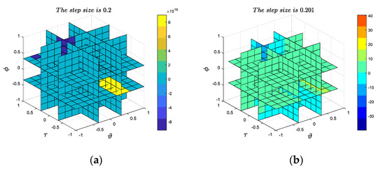
Figure 1.
(a) The symmetric catastrophe function selects every 0.2 steps to calculate the four-dimensional graph; (b) the symmetric catastrophe function selects every 0.201 steps to calculate the four-dimensional graph.
According to catastrophe theory, we construct a special symmetric catastrophe function to simulate the occurrence of a catastrophe. In APNF, under the action of the symmetric catastrophe function, the values of the maximum and secondary impact factors will show a big difference before and after (i.e., the occurrence of a catastrophe). The change of the two values will eventually lead to the critical transitions of the positive and negative feedback. The foregoing are the relevant theoretical bases and core ideas of APNF. The control strategy of the APNF model will then be introduced.
3. APNF Control Strategy
This section mainly introduces the APNF control strategy and the update rules of its corresponding parameters.
3.1. APNF Control Algorithm
For the third-order system with the form of a transfer function, the incremental control principle is adopted to describe the algorithm of the APNF model, which can be obtained according to the recursion scheme as shown below:
where is the output control quantity of the system at time , is the increment of the output control quantity of the system at time , is the proportionality coefficient, is the output response of the system, is the input set value of the system, is the error feedback, and , and . , and can be obtained from (2)–(4) as:
where , and are the control variables of , and the specific solution method is given in Section 3.2.
3.2. Learning Rules Based on Error and Forward Weight
According to (8)–(12), it is necessary to know , and before solving , and the solutions of the three should be calculated on the basis of the set error and forward weight value learning rules. The basic idea of the calculation based on the set error and forward weight value learning rules is as follows: when investigating the object, we should focus on inspecting the object comprehensively and accurately in terms of the interrelation, interaction, and restriction between the whole interior and the parts (elements), and between the whole and the external environment. Here, the forward weight is regarded as an internal factor, and the error is regarded as an external factor. The two are linearly combined to update the parameters, as shown in (13)–(15) as:
where , , , ,, is the set learning rate. Because , , , ,, is an arbitrary constant, can be regarded as a whole, and (13)–(15) are rewritten as shown below:
We show the specific algorithm of APNF in Algorithm 1.
| Algorithm 1. APNF Algorithm. |
| Require: Control objective system in discrete case |
| Require: Input command of controlled object |
| Output: APNF output response |
| 1: Set sampling times , Z-transformation is used to calculate the discretization of , the discretized object is set to |
| 2: Set parameters with |
| 3: Initialize and |
| 4: Initialize |
| 5: Set the number of iterations |
| 6: for do |
| 7: Compute according to Equation (7) |
| 8: Use to calculate vector |
| 9: Updata and based on Equations (16)–(18) |
| 10: Evaluate and in Equations (8) and (9) |
| 11: Compute , and as given in Equations (10)–(12) |
| 12: Evaluate according to Equation (6) |
| 13: Updata in Equation (5) |
| 14: Updata the value of discretized object |
| 15: end for |
4. Stability Analysis
In this section, the stability of the APNF model is analyzed on the basis of the Lyapunov stability theory. For the stability of the APNF system, the theorems below were established.
Theorem 1.
The stability of the APNF model is guaranteed if the learning rate satisfies
Proof.
First of all, define a discrete Lyapunov function as:
During the training process of the Lyapunov function, changes to (21):
Take the weight vector , where can be described by (22)–(24) as:
The expression of can be obtained from (23) and (24), as shown in (25) as:
At the same time, we can know the equivalent expression of (21), as shown below:
Substitute (25) into (26) to get the below:
According to the Lyapunov stability theorem, the system is stable if at any sampling time. It can be seen from (27) that are all numbers greater than 0, so a sufficient condition for is:
where is described as follows:
□
Theorem 2.
The variable is defined as, where. The other variable is described as, where. The convergence of the APNF model is guaranteed if the learning rate satisfies
Proof.
From the chain rule:
substitute (31) into (24) and (25) to get:
Substitute (33) into (26) to get:
According to (10), we can know the following:
It can be obtained from (35)–(37):
According to (9), the maximum impact factor of the symmetric catastrophe function is , which can be obtained as shown below:
The corresponding derivative can be obtained from (39):
The meaning of (40) is that the symmetric catastrophe functions and are used to derive , , and , respectively, in four cases (corresponding to the four cases of (39): ). According to (40), when , can be written as:
In the same way, we can obtain other formulas, as shown below:
Note that in and , for the functions of type and , if is a high-order infinitesimal of , as shown in Figure 2a and Figure 3a, the value of tends to infinity, and no limit exists. As shown in Figure 2b and Figure 3b, when , is a small finite quantity such as 1, has the supremum.
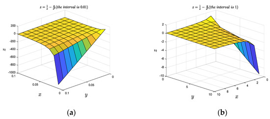
Figure 2.
(a) The type function selects a three-dimensional image calculated at every 0.01 step size; (b) the type function selects a three-dimensional image calculated at every 1 step size.
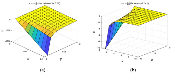
Figure 3.
(a) The type function selects a three-dimensional image calculated at every 0.01 step size. (b) the type function selects a three-dimensional image calculated at every 1 step size.
Here, we assume that the minimum values of and in the experiment are limited; that is, is the supremum. In fact, the following experiments show that the minimum values of and are indeed limits, and the hypothesis is reasonable. From this we can deduce that has the supremum, and let be the supremum of . That is to say:
Meanwhile, let another variable, , be the supremum of . We can obtain:
From (34), (46), and (47), the inequality relation below can be obtained:
When , satisfies:
□
5. Equivalent Positive Feedback
Positive feedback is used in APNF. The simplest idea to realize the combination of the two control modes in the model is to establish the framework of the two control modes in the controller, and then use different frameworks for control at different times through condition judgment. However, in practical research, knowing how to make condition judgment is very difficult. Here, we get inspiration from the equivalence of positive feedback and negative feedback. In a single framework, we do not need to make conditional judgment, and only realize the state transition through the change of parameters. According to the control theory, when the system is a negative feedback system, , and when the system is a positive feedback system, . The PID controller can be cited as an example here to introduce how negative feedback is equivalent to positive feedback, which is related to the realization of positive feedback in APNF. In this section, a theoretical proof of equivalent positive feedback is given.
The PID controller is controlled by three adjustable parameters, which determine the performance of the controller: the proportional gain (), integral gain (), and differential gain (). The PID controller works by continuously monitoring the difference between the set value and the measured process variable. The three aforementioned components are used to calculate the control quantity and to control the target work. The generalized PID control strategy can be expressed by (50):
where the three parameters ,, and are all non-negative, and is the error between the set value and the actual feedback value. Some systems may need to keep only some parameters and set the other parameters to 0 to provide appropriate control, such as the PI, PD, and P controllers.
Theorem 3.
In APNF, when,,, the corresponding gains of,,of negative feedback can be equivalent to the corresponding gains of,,of positive feedback.
Proof.
When , the negative feedback proportional gain can be equivalent to the following:
where is the small difference between and , and is the proportional gain of the equivalent positive feedback. When exists, according to (51), the gain under negative feedback can be transformed into gain under positive feedback. The updated formula is shown below:
Meanwhile, according to the positive feedback control principle, increases with time, so when time t tends to infinity, converges to . That is:
When is negative, the integral and differential gains of negative feedback are equivalent, as follows:
where is a number greater than 1, and and are the integral and differential gains of the equivalent positive feedback, respectively. Through (54) and (55), the and gained under negative feedback can be transformed into and gained under positive feedback. Below are the updated formulas:
Similar to (53), when time tends to infinity, also converges to while is different from and , and its value is always consistent with that of .
□
6. Simulation Results
To verify the feasibility and effectiveness of the proposed APNF control model, we consider a numerical simulation, take a common third-order system as an example to simulate the control, and analyze its control performance.
The control object of the experiment is the third-order control system described in [24], and the transfer function of the controlled object is shown in (59):
First, the step response of the system is considered, and the step signal with a 0.02 M amplitude is inputted into the system described by (59) to test the step response of the system. Figure 4 shows the step response of the system. It can be seen that the system finally reaches a stable state without overshoot. However, the disadvantage is that the response to the input signal is very slow, as shown in Figure 4: the time for the system to reach the stable state is about 12 s, which represents a serious lag, and cannot meet the actual requirements of rapid response of the system.
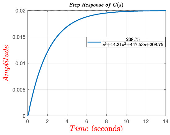
Figure 4.
Step response of with a 0.02 M input.
How to realize positive feedback is the key of the APNF control model. Due to the existence of a symmetric catastrophe function, a small perturbation will cause the positive parameters to change to negative parameters. According to Theorem 3, the negative feedback system with negative parameters is equivalent to positive feedback. It is necessary to further understand Theorem 3, which is of great significance for understanding the nature of APNF. Therefore, before simulating the APNF control model, we performed the equivalent experiment of negative feedback.
Example 1.
In addition to proving Theorem 3 theoretically, we also set up two experiments to verify the relevant conclusions. The controlled object is the system described by (59). In order to show that the positive feedback proposed above can enhance some activities, the consistency of the two strategies is shown when the output is infinite. One of the experimental control strategies is the PID control, described in (50), [24] gives a set of PID control parameters with good effect for (59). Here, we take the opposite number as the control parameters, and the parameter selection is, which represents the influence of negative parameters on the system under the condition of negative feedback. The control strategy of another experiment is, whereis a positive feedback control andandare updated iteratively according to (52), (56), and (57), in which the initial parameters are.
Figure 5 shows the comparison curve of PID control with negative gain and the corresponding equivalent positive feedback step response according to Theorem 3. The purple solid line represents the step response of the PID control strategy in the case of negative parameters, and the dotted line represents the step response of equivalent positive feedback. It can be seen in Figure 5 that the two curves coincide, which indicates that the output result of the negative parameter system under negative feedback is consistent with that of the set positive feedback. The conclusion of Theorem 3 was verified theoretically and experimentally. Meanwhile, from the change of the slope of the output curve, we can see that the positive feedback control can enhance some activities of the system, and speed up the process of some activities. Figure 6a shows the time-varying curve of in the corresponding positive feedback control strategy. The large graph shows the parameter variation of 10 s, and the subgraph shows the parameter variation of 28 s. It can be seen in the graph that, according to the adaptive tuning of (52), finally converges to 4.0. Figure 6b shows the time-varying curve of in the corresponding positive feedback control strategy. It can be seen in the said figure that finally converges to 10.0 according to the adaptive tuning of (57), and remained unchanged during the training (0.001).
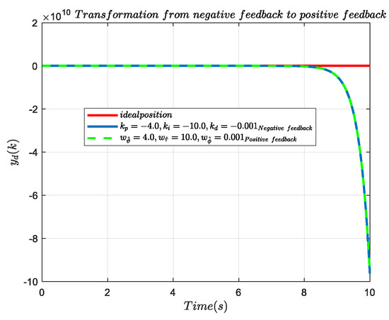
Figure 5.
PID control strategy with negative parameters and step response of the corresponding equivalent positive feedback.
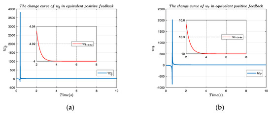
Figure 6.
(a) Parameter change of within 10 s and 2–8 s of equivalent positive feedback; (b) parameter change of within 10 s and 2–8 s of equivalent positive feedback.
Through example 1, we have proven the correctness of Theorem 3 in the experimental aspect. Now, we further simulate and analyze the APNF control model to verify the effectiveness of the proposed model.
Example 2.
The APNF control model proposed in this paper is simulated, and the control object is still the control system described by (59). The simulation results are compared and analyzed with the results of other control strategies.
We deal with the APNF control strategy in a discrete way, and the sampling time is 0.01 s. Table 1 shows the parameter settings in the APNF control system. According to the data in Table 1, the APNF model is established and added to the system for control. The 0.02 M step signal is inputted into the system as the input signal. The performance response curve is shown in Figure 7a, Figure 8a and Figure 9a. The error curve of the APNF performance response output and input with time is shown in Figure 7b, Figure 8b and Figure 9b. The response speed and overshoot of the system are important criteria to judge the performance of the controller. It can be seen in Figure 7 that APNF has a satisfactory control effect. The system converges to the desired position in a short time and reaches a stable state at about 1.3 s. Compared with 12 s, the response speed of the system is greatly improved, and there is no overshoot in the system, both of which meets the design requirements. In order to show the superiority of APNF model, we also performed some comparative experiments of the general controller. The PID control model was established according to (50), and appropriate relevant parameters were selected for simulation, in which the value was 4.0, the value was 10.0, and the value was 0.001. Figure 8 shows the response performance comparison curve of the APNF and other control models (PID, the genetic algorithm based PID (GA-PID), and the particle swarm optimization algorithm based PID (PSO-PID) under the same sampling time and input signal, and Figure 9 shows the response performance output and input error comparison curve of the APNF and other control models under the same sampling time and input signal. As can be seen from Figure 8 and Figure 9, in terms of response speed, under the PID control strategy, the system needs more than 5.5 s to converge to the desired position, GA-PID needs about 1.8 s, and PSO-PID needs approximately 5 s. Although it also shortens the time to reach the stable state compared with 12 s without control, the response speed is still lower than APNF. In terms of overshoot, the three controllers have overshoot in varying degrees, among which PID overshoot is the largest, approximately 35%, GA-PID is approximately 5%, and PSO-PID is approximately 4.8%. In [24], fuzzy control is proposed for the system. The control object is the same as that in this paper, which can effectively improve the response speed, but 2.2 s is still needed for the system to reach the stable state, and the overshoot is 0. Readers interested in fuzzy control can read [24]. A comparison of the output results of the four models reveals that the APNF model not only has a faster system response speed, but also has no overshoot, which obviously has an effect and effectively saves time consumption. Table 2 shows the comparison results of five control strategies.

Table 1.
Parameters involved in APNF model.
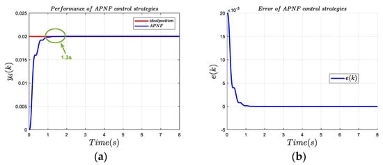
Figure 7.
(a) Response performance curve of the APNF control system; (b) response performance error curve of the APNF control system.
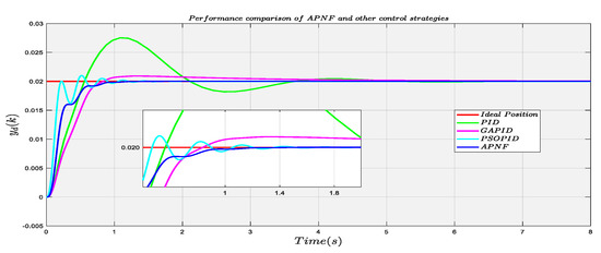
Figure 8.
Response performance comparison curve of the four control systems.
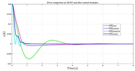
Figure 9.
Response performance error comparison curves of the four control systems.

Table 2.
Comparison of five control methods of system.
Figure 10a shows the curve of changing with the system time in the APNF model, in which the big picture is the parameter change within 8 s system training. To show the internal change rule more clearly, the subgraph of parameter change within 1 s is added. After carefully study of Figure 10a, it was found that the change of the maximum impact factor does not rise or fall steadily, and does not converge to a certain value when the system reaches a stable state. A sudden catastrophe occurs at every other time period, however, showing a law of continuous rise of positive and negative absolute values. Figure 10b shows the parameter curve of with time within 1.2 s and 8 s, and Figure 10c shows the parameter curve of with time within 0.8 s and 8 s. At the same time, it can be seen in Figure 10 that and in (8) and (9) are both numbers greater than a certain limited value, so it can be inferred that the hypothesis and conclusion mentioned in (46) are reasonable. Figure 11 shows the parameter curve of with a time within 0.5 s and 8 s respectively. After careful study of Figure 11, it was found that the value of parameter is always greater than 0, while parameters and oscillate up and down around the 0-axis. This law can be clearly observed from Figure 11b, but Figure 11c has some difficulties; therefore, we also display sign () and sign (). Figure 12 shows the curve of sign () and sign () changing with the system time. The solid line represents sign (), and the dotted line represents sign (). It can be seen in Figure 12 that the two curves coincide, which indicates that the change law of the two curves at the same moment is the same. From Theorem 3 and its generalization, we successfully achieve the equivalence of positive and negative feedback by changing the parameters in only one framework, in which the negative feedback system with negative parameters is equivalent to the positive feedback system with positive parameters. Therefore, according to the change of parameters, under the action of the symmetric catastrophe function, the APNF model realizes the continuous alternating operation of positive and negative feedback, and acts on the control system. When the parameters and are positive, the system is a negative feedback system, and when the parameters are negative, the system is a positive feedback system.
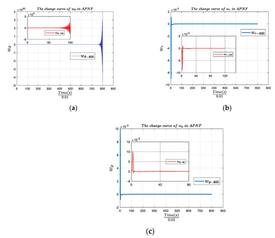
Figure 10.
(a) Parameter change curve of within 1 s and 8 s of APNF; (b) parameter change curve of within 1.2 s and 8 s of APNF; (c) parameter change curve of within 0.8 s and 8 s of APNF.
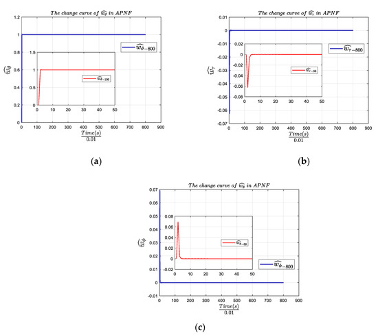
Figure 11.
(a) Parameter change curve of within 0.5 s and 8 s of APNF; (b) parameter change curve of within 0.5 s and 8 s of APNF; (c) parameter change curve of within 0.5 s and 8 s of APNF.
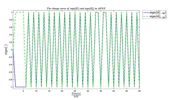
Figure 12.
Parameter change curve of and within 0.5 s of APNF.
The simulation results show that the APNF control scheme proposed in this paper can effectively improve the control efficiency of the system, and can make the system respond faster. The experiment also verified that the negative parameter system could be equivalent to the positive feedback under the negative feedback. Hence, the simulation results confirm the effectiveness of the proposed scheme.
7. Discussion
Through theory and experiments, we prove that the system with two different feedback modes, as a tunable motif, shows different states, and is stable when the relevant parameters change. Specifically, when the positive and negative conversion of relevant parameters occurs, the system will experience the transformation of negative feedback state and positive feedback state. As shown in Figure 12, the symbol changes of and are synchronous after 0.05 s, indicating that the system state is in one of the two states at a certain time, and becomes the other at the next time. In summary, the system with different feedback modes is a tunable motif such that the desirable dynamic behavior can be realized by tuning the system state.
We explain the equivalent form of positive feedback and negative feedback. At present, many researchers focus on a single feedback mode when setting up the control system, ignoring the possibility of the combination of positive feedback and negative feedback. Positive feedback quickly reaches the desired dynamic behavior, but does not maintain a steady state and the output goes to infinite, while negative feedback remains steady, but lags significantly. Compared with other general control methods, the focus of this paper is to use positive feedback to quickly reach the desired behavior, use negative feedback to suppress the uncontrollability of the output, and realize the adaptive transformation of the two states simultaneously. Our research shows that it is feasible for a controller to integrate multiple feedback methods, which is not limited to single direction control, and hopefully this work can bring some different inspiration to other researchers in related fields.
Note that the traditional controller based on optimization algorithm is based on stochastic process, which means that the system may require many times and a longer time to reach the optimal value or the controller is sometimes fail to converge on the basis of experience, relying on the researchers’ prior knowledge, access to adequate and effective prior knowledge is a complex work for researchers, but APNF algorithm automatically adjusts relevant parameters by considering the current response of the system, and only needs to set appropriate initialization parameters. There are only two kinds of states involved in the APNF model: positive and negative feedback; however, we will research whether there are other states, such as states in between, in an attempt to improve the model so that the system can realize transitions in more than two states in the future. In addition, we also intend to extend the model to other fields, such as researching its effect on nonlinear systems.
8. Conclusions
This paper analyzes a control strategy that could lead the system realize different state transitions adaptively. On the basis idea of catastrophe theories’ elements, the model of how to realize APNF in the control system was examined. In the APNF model, a symmetric catastrophe function is constructed to realize the critical transitions of negative and positive feedback. Meanwhile, a learning rule based on error and forward weight is established to calculate the impact factor. In addition, the convergence of APNF is proven according to the Lyapunov stability theory, and how the negative feedback system with negative parameters is equivalent to the positive feedback system is also proven. Two simulation examples show the effectiveness of the APNF model.
Author Contributions
Conceptualization, T.Z. and F.Z.; methodology, F.Z. and T.Z.; software, W.H., F.Z., P.L., Y.X., J.L. and Y.D.; validation, F.Z., and P.L., Y.X., J.L. and Y.D.; formal analysis, F.Z.; investigation, W.H. and F.Z.; resources, F.Z., Y.X. and J.L.; data curation, F.Z., P.L., Y.X., J.L. and Y.D.; writing—original draft preparation, F.Z.; writing—review and editing, W.H; visualization, F.Z., P.L., Y.X., J.L. and Y.D.; supervision, W.H.; project administration, T.Z.; funding acquisition, W.H. All authors have read and agreed to the published version of the manuscript.
Funding
This work was supported by the Guangzhou Science and Technology Planning Project under Grant No.: 202002030279.
Institutional Review Board Statement
Not applicable.
Informed Consent Statement
Not applicable.
Data Availability Statement
Not applicable.
Acknowledgments
The authors want to thank Guangzhou University for its support.
Conflicts of Interest
The authors declare no conflict of interest.
References
- Han, S.; Choi, M.Y.; Kumar, P.; Stanley, H.E. Phase transitions in confined water nanofilms. Nat. Phys. 2010, 6, 685–689. [Google Scholar] [CrossRef] [Green Version]
- Wu, H.; Zhu, J.; Zhang, T. Pseudo-first-order phase transition for ultrahigh positive/negative electrocaloric effects in perovskite ferroelectrics. Nano Energy 2015, 16, 419–427. [Google Scholar] [CrossRef]
- Haurie, A.; Moresino, F. A stochastic control model of economic growth with environmental disaster prevention. Automatica 2006, 42, 1417–1428. [Google Scholar] [CrossRef] [Green Version]
- Zannotti, A.; Diebel, F.; Denz, C. Dynamics of the optical swallowtail catastrophe. Optica 2017, 4, 1157–1162. [Google Scholar] [CrossRef]
- Liu, Y.; Zhai, M.; Jin, J.; Song, A.; Lin, J.; Wu, Z.; Zhao, Y. Intelligent online catastrophe assessment and preventive control via a stacked denoising autoencoder. Neurocomputing 2020, 380, 306–320. [Google Scholar] [CrossRef]
- Wright, M.; Deacon, G. A catastrophe theory of planar orientation. Int. J. Robot. Res. 2000, 19, 531–565. [Google Scholar] [CrossRef]
- Zhao, X.; Sun, Y.; Qi, Z.; Han, M. Catastrophe characteristics and control of pitching supercavitating vehicles at fixed depths. Ocean. Eng. 2016, 112, 185–194. [Google Scholar]
- Lin, Y.; Yan, H. Model of alternate positive negative feedbackics and its applications. J. Syst. Eng. 2018, 33, 14–26. [Google Scholar]
- Zhao, J. Adaptive multi-dimensional Taylor network dynamic surface control for a class of strict-feedback uncertain non-linear systems with unmodeled dynamics and output constraint. ISA Trans. 2021, 108, 35–47. [Google Scholar]
- Angeli, D. Almost global stabilization of the inverted pendulum via continuous state feedback. Automatica 2001, 37, 1103–1108. [Google Scholar] [CrossRef]
- Ornik, M.; Carr, S.P.; Israel, A.; Topcu, U. Control-Oriented Learning on the Fly. IEEE Trans. Autom. Control. 2020, 65, 4800–4807. [Google Scholar] [CrossRef]
- Xing, L.; Wen, C.; Zhu, Y.; Su, H.; Liu, Z. Output feedback control for uncertain nonlinear systems with input quantization. Automatica 2016, 65, 191–202. [Google Scholar] [CrossRef]
- Wang, F.; Chen, B.; Lin, C.; Zhang, J.; Meng, X. Adaptive Neural Network Finite-Time Output Feedback Control of Quantized Nonlinear Systems. IEEE Trans. Cybern. 2018, 48, 1839–1848. [Google Scholar] [CrossRef]
- Li, Y.-X.; Yang, G.-H. Adaptive Neural Control of Pure-Feedback Nonlinear Systems with Event-Triggered Communications. IEEE Trans. Neural Netw. Learn. Syst. 2018, 29, 6242–6251. [Google Scholar] [CrossRef]
- Wu, C.; Liu, J.; Xiong, Y.; Wu, L. Observer-Based Adaptive Fault-Tolerant Tracking Control of Nonlinear Nonstrict-Feedback Systems. IEEE Trans. Neural Netw. Learn. Syst. 2017, 29, 1–12. [Google Scholar] [CrossRef] [PubMed]
- He, Y.; Wang, X.; Ruan, X.; Pan, D.; Xu, X.; Liu, F. Capacitor-Current Proportional-Integral Positive Feedback Active Damping for LCL-Type Grid-Connected Inverter to Achieve High Robustness Against Grid Impedance Variation. IEEE Trans. Power Electron. 2019, 34, 12423–12436. [Google Scholar] [CrossRef]
- Omidi, E.; Mahmoodi, N. Hybrid Positive Feedback Control for Active Vibration Attenuation of Flexible Structures. IEEE/ASME Trans. Mechatron. 2015, 20, 1790–1797. [Google Scholar] [CrossRef]
- Qi, N.; Yuan, Q.; Liu, Y.; Huo, M.; Cao, S. Consensus vibration control for large flexible structures of spacecraft with modi-fied positive position feedback control. IEEE Trans. Control. Syst. Technol. 2019, 27, 1712–1719. [Google Scholar] [CrossRef]
- Zhao, G.; Paknejad, A.; Raze, G.; Deraemaeker, A.; Kerschen, G.; Collette, C. Nonlinear positive position feedback control for mitigation of nonlinear vibrations. Mech. Syst. Signal Process. 2019, 132, 457–470. [Google Scholar] [CrossRef] [Green Version]
- Qi, Z.; Shi, Q.; Zhang, H. Tuning of Digital PID Controllers Using Particle Swarm Optimization Algorithm for a CAN-Based DC Motor Subject to Stochastic Delays. IEEE Trans. Ind. Electron. 2019, 67, 5637–5646. [Google Scholar] [CrossRef]
- Moura, J.; Neto, J.; Rêgo, P. A neuro-fuzzy model for online optimal tuning of PID controllers in industrial systems applica-tions to the mining sector. IEEE Trans. Fuzzy Syst. 2019, 28, 1864–1877. [Google Scholar] [CrossRef]
- Pan, Y.; Li, X.; Yu, H. Efficient PID Tracking Control of Robotic Manipulators Driven by Compliant Actuators. IEEE Trans. Control. Syst. Technol. 2019, 27, 915–922. [Google Scholar] [CrossRef]
- Zuo, H.; Liu, G.; E, J.; Zuo, W.; Wei, K.; Hu, W.; Tan, J.; Zhong, D. Catastrophic analysis on the stability of a large dish solar thermal power generation system with wind-induced vibration. Sol. Energy 2019, 183, 40–49. [Google Scholar] [CrossRef]
- Jin, X.; Chen, K.; Zhao, Y.; Ji, J.; Jing, P. Simulation of hydraulic transplanting robot control system based on fuzzy PID con-troller. Measurement 2020, 164, 108023. [Google Scholar] [CrossRef]
- Li, J.; Li, W. On-Line PID Parameters Optimization Control for Wind Power Generation System Based on Genetic Algorithm. IEEE Access 2020, 8, 137094–137100. [Google Scholar] [CrossRef]
- Tran, H.K.; Chiou, J.-S.; Dang, V.-H. New Fusion Algorithm-Reinforced Pilot Control for an Agricultural Tricopter UAV. Mathematic 2020, 8, 1499. [Google Scholar] [CrossRef]
Publisher’s Note: MDPI stays neutral with regard to jurisdictional claims in published maps and institutional affiliations. |
© 2021 by the authors. Licensee MDPI, Basel, Switzerland. This article is an open access article distributed under the terms and conditions of the Creative Commons Attribution (CC BY) license (https://creativecommons.org/licenses/by/4.0/).