1. Introduction
Hybrid electric powertrains are widely used in mining trucks; a combustion engine rotates a wound rotor synchronous generator, producing AC voltage, which is then rectified. This electric energy supplies traction to the electric motors mounted in the wheels of a truck. Nowadays, both DC and AC motors are utilized as traction drives of these mining trucks. The significant drawback of DC motors is well known: an unreliable brush-collector unit. The rapid development of power semiconducting devices has led to the creation of reliable frequency converters and the feasibility of using brushless AC traction motors in truck powertrains. Currently, the induction AC motor is the most widespread solution for mining trucks [
1], and DC motor powertrains have been discontinued. The usage of traction induction motors significantly increases the reliability of traction electric drives in comparison with the brushed DC motor and reduces the operating costs associated with the maintenance and replacement of brushes. However, induction traction motors in mining trucks have the following main disadvantages: reduced reliability due to the high risk of failure of the welded rotor winding [
2], increased overheating due to high losses in the rotor [
3], reduced speed control range in comparison with synchronous machines [
4], impossibility of reliable sensorless control over the entire speed range due to the inapplicability of the self-sensing position estimation methods [
3,
5], and limitations in the use of pure electric brakes during a standstill due to the thermocycling of semiconducting devices.
To eliminate the above-described disadvantages of powertrains with induction electric motors, a traction synchronous homopolar motor (SHM) with the rated power of 320 kW was developed for the BELAZ 75570 mining truck (manufacturer is Belarusian Automobile Plant) with a carrying capacity of 90 tons. Two traction SHMs are installed in the two rear wheels of the mining truck. In [
4,
5], the inverter was described and the development of sensorless control algorithms for the traction SHM was highlighted.
The SHM has a complex magnetic core layout, which requires the calculation of a three-dimensional magnetic field, which makes its magnetic analysis challenging. The magnetic flux flows axially in the rotor sleeve and in the stator yoke; however, it changes its direction to transverse in the stator and rotor laminated cores.
Three kinds of models were proposed for the evaluation of the characteristics of the SHMs: the first is the 3D finite element method (FEM) [
6,
7]; the second is the 2D FEM [
8,
9], where the axial and radial fluxes are evaluated using a magnetic circuit; and the third is the 1D [
6,
10] lumped parameters-equivalent circuit. The 3D FEM provides the most accurate field calculation; however, the use of any method of mathematical optimization together with it is barely possible due to the very long time required by one calculation. Two-dimensional FEM models of SHMs described in [
8,
9] have a much shorter computation time, but they are not as accurate, due to the introduction of virtual windings into the computational area, imitating the axial excitation flux due to the substitution of the SHM with a salient-pole synchronous machine, which causes an additional error. One-dimensional-equivalent circuits provide the shortest calculation time, but they do not take into account the details of the machine geometry, and they give the largest error.
The article [
11] described a new method of the mathematical modeling of SHMs, which is based on the 2D FEM. In contrast to the mathematical models of SHMs based on the 3D FEM [
7,
8], this method requires less computation time and is less demanding on the available computing resources. The calculation results obtained using this model were in good agreement with the experimental results. However, the traction SHM was developed without using any optimal design methods such as the genetic algorithm or the Nelder–Mead method. Therefore, the characteristics of the traction SHM described in [
11] can be improved.
Synchronous homopolar machines have been known for a long time and are used in various equipment such as generators in aircrafts and trains [
12], welding inverters [
13], and flywheel energy storage systems [
14]. Moreover, in [
4,
5,
11,
15,
16], SHMs were presented as traction motors. In [
17], the design of an SHM for a flywheel energy storage was considered with the use of ‘manual’ optimization of the SHM parameters based on a lumped model to obtain a higher efficiency of the machine. However, no mathematical methods of optimal design have been adopted for traction SHMs yet.
This paper discusses various aspects of the optimal design of traction SHM, applying the Nelder–Mead method. The objective function for the SHM optimization was designed to reduce/improve the following main characteristics: total motor power loss, maximum winding current, and torque ripple.
2. SHM Design Features
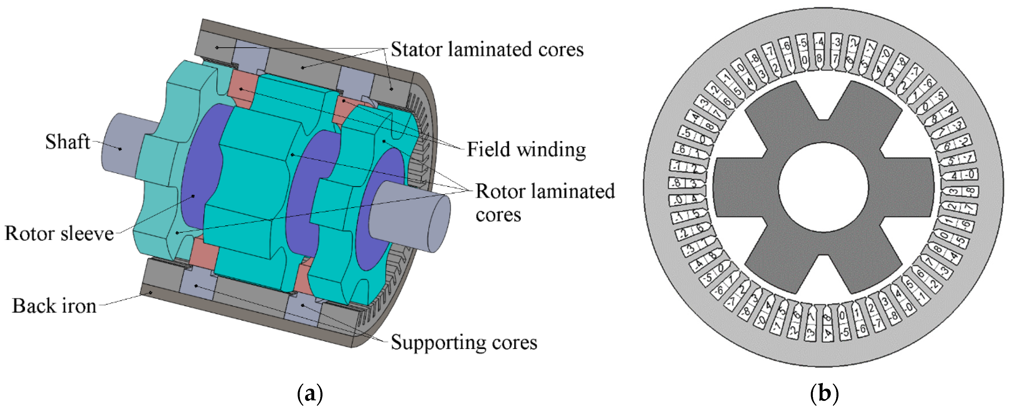
Figure 1a shows a sketch of the SHM with the number of stator and rotor stack combinations (SRSCs) equal to 3. The rotor stacks are mounted on the sleeve pressed onto the motor shaft. The stator stacks are pressed into the housing (back iron). The excitation coils are located in the gaps between SRSCs. A single stator winding is placed in the slots of all stator stacks. Each rotor core has 6 teeth, which corresponds to the number of pole pairs
p = 6 of the stator armature winding. The motor electric frequency can be expressed through rotational speed
n given in revolutions per minute by the formula:
f =
p ×
n/60. The mechanical and electrical angular frequencies are defined as Ω = 2 × π ×
n/60 and ω = 2 × π ×
f, respectively. The stator has
Zs = 54 slots. The electromagnetic analysis was carried out for 2 poles and
Zs/
p = 9 stator slots.
To reduce the maximum current in the semiconductor switches and reduce the cost of the traction inverter, a nine-phase armature winding whose phases are indicated by the numbers 0–8 in
Figure 1b was used, which consists of three separate three-phase windings, each of which has its own neutral point. The currents in the adjacent phases are shifted by 360°/9 = 40 electrical degrees. The distributed double-layer winding has a coil pitch of four stator slots. The analysis assumes that the phase currents are sinusoidal.
The SHM has two sets of SRSCs with the same mutual orientation of the stator and rotor cores. In the considered case, the first set consists of only the central SRSC, and the second set consists of two lateral SRSCs. The angular position of the lateral rotor stacks is displaced relative to the position of the central rotor stack by 30 mechanical degrees (which is 30 * p = 180 electrical degrees) so that SRSCs produce unidirectional electromotive forces (EMF) in the armature winding. The total stack length of one set must be approximately equal to the total stack length of the other set. For this reason, the length of the central SRSC must be twice those of the lateral SRSCs, as the flux of both field coils flows through it, and the flux of only one of the field coils flows through the lateral SRSCs.
In the case of sinusoidal armature currents, the two sets of SRSC under consideration make the same contribution to the active and reactive power, as well as to the torque. However, their instantaneous values of EMF and torque are not exactly the same. For this reason, the calculation method of SHM performances includes two steps. In the first step, it is assumed that the SHM has only one SRSC, the length of which is equal to the sum of the lengths of all SRSCs. The dependences of torque, voltage, etc. on the rotor position are calculated using a set of two-dimensional problems of magnetostatics. In the second step, symmetrization is applied to take into account that the torque ripple and the total harmonic distortion of the voltage wave produced by single SRSCs partially extinguish each other, and these parameters of the total machine are much less than those obtained in the first step. These magnetostatic problems are similar to those usually used in modeling radial motors, except that the excitation field is modeled by a magnetic monopole. Then, the symmetrization procedure is applied to spread the results to the real SHM. A detailed description of the mathematical model of SHM is given in [
11].
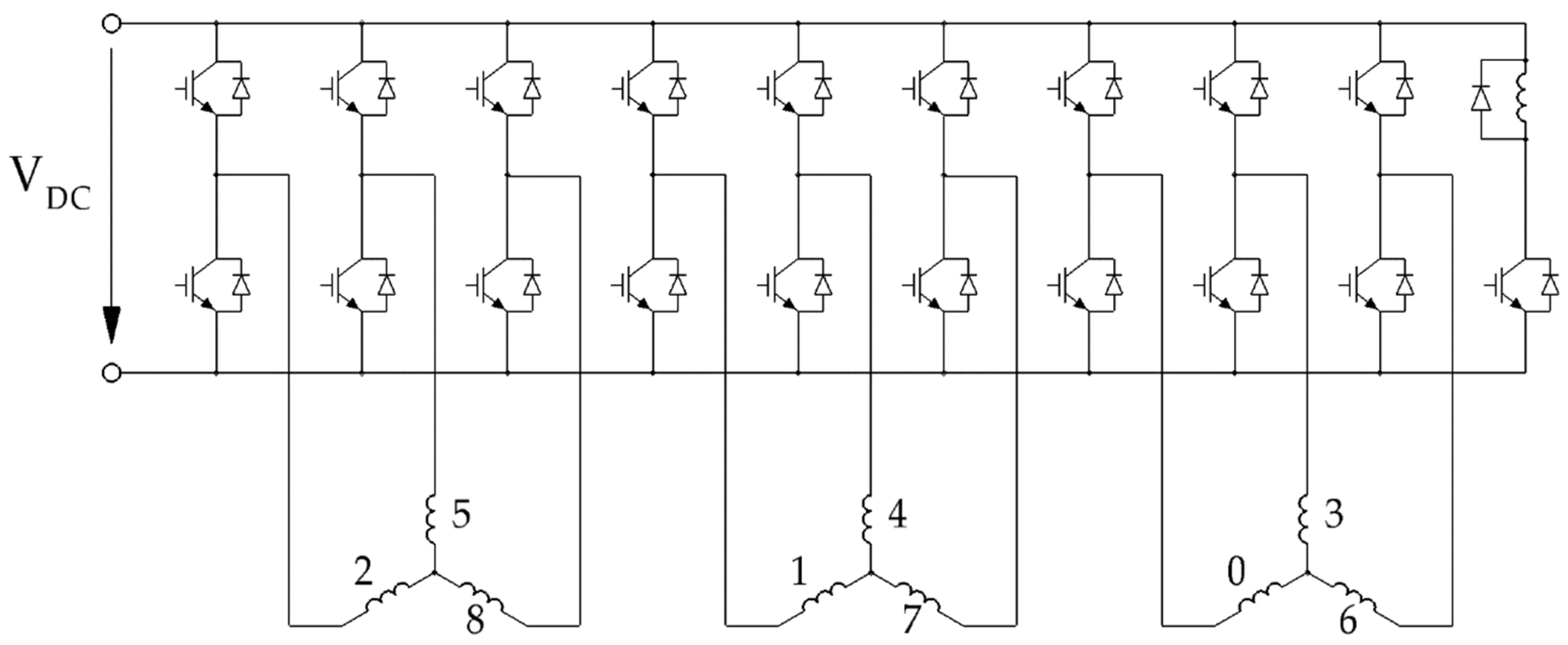
Figure 2 shows the inverter circuit diagram for the traction SHM. The considered nine-phase inverter consists of 3 separate three-phase inverters, and it also has a one-phase chopper for powering the field winding.
3. Construction of an Objective Function for Nine-Phase Traction Synchronous Homopolar Motors
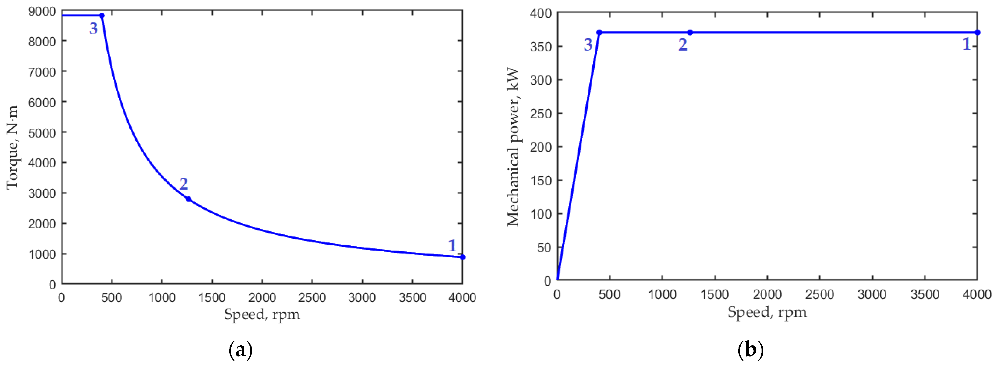
Figure 3 shows the traction characteristic of the electric drive of the BELAZ 75570 mining truck [
3], limited by the maximum rotational speed and the maximum torque. The constant power speed ranges from 400 to 4000 rpm (10:1). The maximum mechanical power of the machine in the motor mode is 370 kW.
When optimizing the motor, three operating points were considered: the points with speeds of 400 rpm (maximum torque) and 4000 rpm (maximum speed), as well as the point with the geometric averages of speed and torque. These operating points are shown in
Table 1.
It is assumed that the SHM can operate with equal probability in the subranges 1–2 and 2–3. It is assumed that the average losses in the subranges are equal to the arithmetic mean of the losses at their boundaries (points 1 and 2 and points 2 and 3, respectively). Therefore, as the first optimization objective, the weighted average loss is chosen:
The other two optimization objectives are maximum symmetrized and nonsymmetrized torque ripples: max(
TR) and max(
TRsym), respectively. A nonsymmetrized torque ripple is produced by single SRSCs. A symmetrized torque ripple is produced by a SHM as a whole. Details of
TR and
TRsym are given in [
11].
The remaining optimization objective is the maximum stator armature winding current
I3 (it is achieved in operating point 3). Therefore, the objective function for the traction SHM optimization is:
This expression indicates that <Plosses> is considered as the most valuable objective. I3 is also a valuable objective. Decreasing I3 by 1% is as valuable as decreasing <Plosses> by 0.7%. max(TRsym) and max(TR) are much less valuable objectives. Decreasing max(TRsym) and max(TR) by 1% is as valuable as decreasing <Plosses> by 0.05% and 0.025%, respectively.
In addition, the following constraints were adopted during the optimization:
where
UDC1 is the maximum voltage that is reached at operating point 1 and
B3 is the maximum flux density in the nonlaminated sections of the magnetic core (the rotor sleeve or the housing).
The one-criterion Nelder–Mead method is applied in this study to optimize the SHM design. The Nelder–Mead method belongs to unconstrained optimization methods. The optimization constraints could be specified simply by assigning infinite values to the objective function when the constraint conditions are not met. However, this would lead to a rapid decrease in the volume of the simplex. For this reason, objective function (2) is modified by using the ‘soft constraints’ with the penalty growing rapidly in the forbidden area:
where
.
Thus, during the optimization process, the constraint conditions can be violated, which prevents a rapid decrease in the simplex. At the same time, if k1 and k2 are large enough—they exceed the corresponding Lagrange multipliers—the optimized design will satisfy the constraints. In this study, it was assumed that k1 = k2 = 1.5, and it turned out that the optimized design satisfied constraints (3).
4. Initial Design and Parameters Varied during Optimization
Figure 4 demonstrates the main geometric parameters of the traction SHM. In the initial design, the lengths of the stator stacks were
Lstat1 = 101 mm,
Lstat2 = 197 mm, and
Lstat3 = 101 mm. The total length of the stator lamination was
Lstat =
Lstat1 +
Lstat2 +
Lstat3 = 399 mm. The lengths of the rotor stacks were less than the lengths of the corresponding stator stacks and were equal to
Lrot1 = 92 mm,
Lrot2 = 184 mm, and
Lrot3 = 92 mm. The total length of the rotor lamination was
Lrot =
Lrot1 +
Lrot2 +
Lrot3 = 368 mm. The parameters changed during optimization, and some fixed parameters are shown in
Table 2 and
Table 3, and
Figure 4. The main dimensions of the machine (outer radius of the stator housing
Rhousing = 367 mm and machine length without end winding parts
L = 545 mm) remained unchanged during the optimization.
The shape of the stator yoke, stator yoke thickness, and rotor yoke thickness did not change. As the external radius of the stator housing Rhousing was fixed, the inner radius of the stator changed as the housing thickness h changed. The outer rotor radius was also influenced by the air gap width δ. As the outer radius of the rotor sleeve Rsleeve and the thickness of the rotor yoke R1 − Rsleeve were fixed, the depth of the rotor slot changed with the change in the outer diameter of the rotor.
The angular distances between the rotor teeth on the outer radius of the rotor and on the inner radius of the rotor slot R1 were changed consistently by multiplying with the coefficient frs. As the outer radius of the rotor sleeve Rsleeve and the radial clearance Δr were fixed, the inner radius of the field winding was also fixed. The axial length of the field winding is Lex = (L − Lstat)/2 − Δa and changes with the variation of Lstat. Lex = 48 mm at the initial design. The resistance of the excitation winding was assumed to be 10.2 Ohms at the initial design. During the optimization, this resistance changed, depending on the length of the field winding as 10.2 Ohm∙48 mm/Lex. The number of turns of the field winding equal to 340 did not change.
The lengths of the stator stacks were slightly longer than the lengths of the rotor stacks. As a result, the excitation field, which is constant in the rotor reference frame, coming out of the ends of the rotor stacks, was closed on the inner surface of the laminated stator. Therefore, additional eddy current losses due to the penetration of the magnetic field into the end surfaces of the stator laminations did not arise. However, the use of the 2D FEM model required the calculation of the equivalent total length of the stator lamination
Lequ [
18]. In this study, it was assumed that the equivalent length increased over the total length of the rotor stacks by 1.26 × δ at each edge of the rotor stack; therefore,
Lequ =
Lrot + 6 × 1.2 × δ. The steel filling factor of the stator and rotor laminations was assumed to be
ksteel = 0.95. The following magnetization curves were adopted for the rotor and stator laminations:
where
H0(
B) is the catalog steel magnetization curve.
5. Traction SHM Optimization Results and Discussion
The Nelder–Mead algorithm described in [
19] was used in designing the traction SHM. The number of optimization parameters was ten (listed in
Table 3). The mathematical model described in [
11] was used to evaluate the objectives included in the optimization function
F (3).
Figure 5 shows plots of flux density magnitude up to 2 T at the initial and optimized designs for the most saturated operating point 3. The contours of the regions of extreme saturation with flux density greater than 2 T were also outlined. As a result of optimization, the overall saturation and the areas of extreme saturation decreased.
Table 3 (see above) shows the varied design parameters of the traction SHM before and after the optimization. Among the varied parameters, the air gap width changed most significantly: it increased 1.4 times. There is a trade-off when choosing the air gap width of the SHM. On the one hand, reducing the gap makes it easier to produce the useful excitation flux. This flux interaction with the current in the armature winding creates the torque. On the other hand, with a small air gap, the leakage flux of the armature winding increases; it does not create the useful torque but only saturates the magnetic core and increases the reactive power. The synchronous homopolar machine has an effective excitation system, in which one excitation winding with ring-shaped coils magnetizes all the poles of the machine. Therefore, the trade-off in choosing the air gap width shifts from increasing the excitation flux to reducing the reactive power and saturation. For this reason, the air gap in the SHM must be increased compared to other types of electrical machines such as induction and reluctance machines. In addition, increasing the air gap width of the SHM increases its robustness, simplifies assembly, improves reliability, and decreases torque ripple.
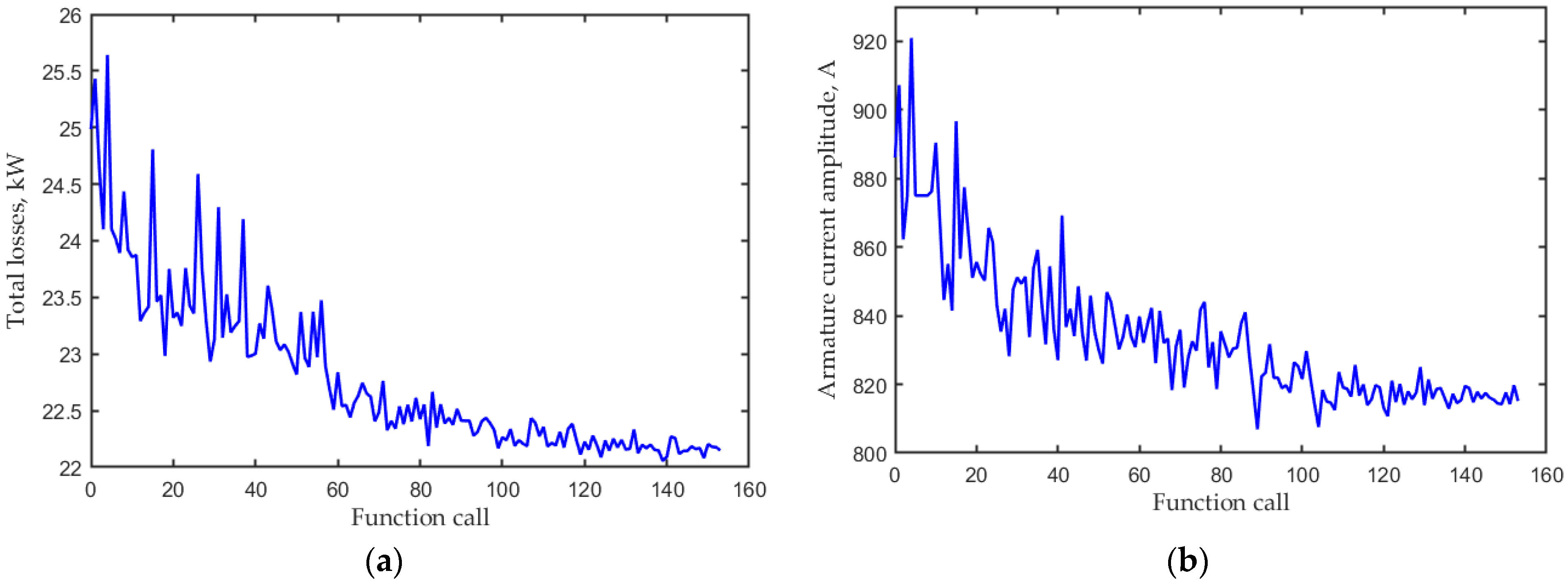
Figure 6 shows the change in the total losses <
Plosses> and the maximum current of the armature winding
I3 in the SHM during optimization.
Figure 7a shows the change in the maximum symmetrized
TRsym and nonsymmetrized torque ripples
TR during optimization.
Figure 7b shows the change in the objective function
F during optimization.
Table 4 shows the main results of the optimization of the traction SHM.
In the motor mode, at operating points 1 and 2, the total losses reduced by 1.13 and 1.16 times, respectively. At operating point 3, only a slight reduction in the total losses was achieved. This loss reduction was probably due to an increase in the air gap width, leading to a weakening in the leakage flux of the armature winding and a decrease in saturation and reactive power. An increase in the air gap width also leads to a weakening in the high harmonics of the flux density in the air gap, which makes it possible to reduce the torque ripple. At operating points 1 and 2 of the motor mode, the symmetrized torque ripple reduced by 1.45 and 1.32 times, respectively. The maximum armature winding current occurring at operating point 3 of the motor mode decreased by 8%. The flux density in the nonlaminated parts of the magnetic core reached a maximum value of 1.65 T at operating point 3.
In [
20], it was reported that in in the braking (generator) mode of the considered application, the highest torque was reached at a speed of 1100 rpm (5200 N·m, 540 kW). For this reason, the calculation results for the braking mode are also presented in
Table 4. In the braking mode, the total losses were also significantly reduced after optimization, although this operating point was not optimized and was not included in the objective function (2), as a mining truck, when driving from a mountain, dissipates all the energy into the braking resistors. As seen in
Table 4, in the braking mode, the voltage and currents were within an acceptable range.
6. Conclusions
This paper discusses various aspects of the optimal design of a traction SHM, applying the one-criterion unconstrained Nelder–Mead method. This SHM is intended for use in a mining dump truck with a carrying capacity of 90 tons.
The objective function for the SHM optimization was designed to reduce/improve the following main characteristics: total motor power loss, maximum winding current, and torque ripple. Optimization was carried out by taking into account the characteristics of the SHM at three loading modes. The constraints of the supplied voltage and of the maximum magnetic flux density in the nonlaminated parts of the magnetic core were imposed.
Among the varied parameters, after the optimization, the air gap width changed most significantly; it increased 1.4 times, which makes it possible to reduce the saturation of the magnetic circuit, reduce the reactive power of the motor, increase the reliability of the motor, simplify assembly, and also to reduce the torque ripple.
As a result of optimization, in the motor mode, at operating points 1 and 2, the total losses reduced by 1.13 and 1.16 times, respectively. At operating point 3, only a slight reduction in the total losses was achieved. At operating points 1 and 2 of the motor mode, the symmetrized torque ripple reduced by 1.45 and 1.32 times, respectively. The flux density in the nonlaminated parts of the magnetic core reached a maximum value of 1.65 T at operating point 3. The maximum armature winding current in the motor mode decreased by 8%. In the braking mode, the total losses of the SHM were also significantly reduced after optimization, although this operating point was not optimized and was not included in the objective function.
In addition, after the optimization, the regions of the motor magnetic core with extreme saturation noticeably decreased, which is one of the reasons for the decrease in losses and an increase in efficiency.
In future works, the SHM will theoretically be considered in other applications, for example, as a traction motor for a light electric vehicle and electric bus. In addition, a theoretical comparison of the SHM with a traction induction motor will be carried out.
Author Contributions
Conceptual approach, A.A., V.D. and V.P.; data duration, V.D. and V.K.; software, V.D. and V.P.; calculations and modeling, A.A., V.D., V.K. and V.P.; writing—original draft, A.A., V.D., V.K. and V.P.; visualization, V.D. and V.K.; review and editing, A.A., V.D., V.K. and V.P. All authors have read and agreed to the published version of the manuscript.
Funding
The research was performed with the support of the Russian Science Foundation grant (Project No. 21-19-00696).
Institutional Review Board Statement
Not applicable.
Informed Consent Statement
Not applicable.
Data Availability Statement
All data are contained within the article.
Acknowledgments
The authors thank the editors and reviewers for their careful reading and constructive comments.
Conflicts of Interest
The authors declare no conflict of interest.
Glossary
| List of Abbreviations |
| AC | Alternating current |
| DC | Direct current |
| EMF | Electromotive force |
| FEM | Finite element method |
| SHM | Synchronous homopolar motor |
| SRSC | Stator and rotor stack combination |
| List of Mathematical Symbols |
| B | Flux density, T |
| B3 | Maximum flux density in the nonlaminated parts of the magnetic core, T |
| f | Electric frequency, Hz |
| F | Second objective function |
| F0 | First objective function |
| f1 | Auxiliary function |
| frs | Rotor slot factor |
| h | Housing thickness, mm |
| H0 | Magnetic field strength according to the catalog magnetization curve, A/m |
| Hrotor | Rotor magnetic field strength, A/m |
| Hstator | Stator magnetic field strength, A/m |
| hlam | Stator lamination height, mm |
| I3 | Amplitude of the maximum stator armature winding current, A |
| k1, k2 | Multipliers of terms of an objective function |
| ksteel | Steel fill factor |
| L | Total machine length without end winding parts, mm |
| Lequ | Equivalent total length of the stator lamination, mm |
| Lex | Axial length of the field winding, mm |
| Lrot | Total length of the rotor lamination, mm |
| Lrot1, Lrot2, Lrot3 | Lengths of individual rotor stacks, mm |
| Lstat | Total length of the stator lamination, mm |
| Lstat1, Lstat2, Lstat3 | Lengths of individual stator stacks, mm |
| n | Rotational frequency, revolution per minute |
| p | Number of pole pairs |
| Plosses | Total power losses, kW |
| R1 | Thickness of the rotor yoke, mm |
| Rhousing | Outer radius of the stator housing, mm |
| Rsleeve | Outer radius of the rotor sleeve, mm |
| Rshaft | Shaft radius, mm |
| TR | Torque ripple, % |
| TRsym | Symmetrized torque ripple, % |
| UDC1 | Maximum voltage, V |
| Zs | Number of stator slots |
| δ | Air gap width, mm |
| Δa | Axial clearance between excitation winding and rotor, mm |
| Δr | Radial clearance between field winding and rotor, mm |
| ω | Electrical angular speed, radian per second |
| Ω | Mechanical angular speed, radian per second |
References
- Koellner, W.; Brown, G.; Rodriguez, J.; Pontt, J.; Cortes, P.; Miranda, H. Recent advances in mining haul trucks. IEEE Trans. Ind. Electron. 2004, 51, 321–329. [Google Scholar] [CrossRef]
- Bernatt, J.; Gawron, S.; Glinka, T.; Polak, A. Traction induction motor. In Proceedings of the 13th International Conference Modern Electrified Transport (MET), Warsaw, Poland, 5–7 October 2017; pp. 1–5. [Google Scholar] [CrossRef] [Green Version]
- Anuchin, A. Development pf Digital Systems for Efficient Control of Traction Electric Equipment for Hybrid Electric Vehicles. Ph.D. Thesis, Moscow Power Engineering Institute, Moscow, Russia, 2018; pp. 1–445. Available online: https://mpei.ru/diss/Lists/FilesDissertations/365-%D0%94%D0%B8%D1%81%D1%81%D0%B5%D1%80%D1%82%D0%B0%D1%86%D0%B8%D1%8F.pdf (accessed on 2 June 2021). (In Russian).
- Lashkevich, M.; Anuchin, A.; Aliamkin, D.; Briz, F. Control strategy for synchronous homopolar motor in traction applications. In Proceedings of the 43rd Annual Conference of the IEEE Industrial Electronics Society (IECON), Beijing, China, 29 Octobe–1 November 2017; pp. 6607–6611. [Google Scholar] [CrossRef]
- Lashkevich, M.; Anuchin, A.; Aliamkin, D.; Briz, F. Self-sensing control capability of synchronous homopolar motor in traction applications. In Proceedings of the 2017 IEEE 58th International Scientific Conference on Power and Electrical Engineering of Riga Technical University (RTUCON), Riga, Latvia, 12–13 October 2017; pp. 1–5. [Google Scholar] [CrossRef]
- Belalahy, C.; Rasoanarivo, I.; Sargos, F. Using 3D reluctance network for design a three phase synchronous homopolar machine. In Proceedings of the 2008 34th Annual Conference of IEEE Industrial Electronics, Orlando, FL, USA, 10–13 November 2008; pp. 2067–2072. [Google Scholar] [CrossRef]
- Cheshmehbeigi, H.; Afjei, E. Design Optimization of a Homopolar Salient-Pole Brushless DC Machine: Analysis, Simulation, and Experimental Tests. IEEE Trans. Energy Convers. 2013, 28, 289–297. [Google Scholar] [CrossRef]
- Ye, C.; Yang, J.; Xiong, F.; Zhu, Z.Q. Relationship between homopolar inductor machine and wound-field synchronous machine. IEEE Trans. Ind. Electron. 2020, 67, 919–930. [Google Scholar] [CrossRef] [Green Version]
- Yang, J.; Ye, C.; Liang, X.; Xu, W.; Xiong, F.; Xiang, Y.; Li, W. Investigation of a Two-Dimensional Analytical Model of the Homopolar Inductor Alternator. IEEE Trans. Appl. Supercond. 2018, 28, 5205205. [Google Scholar] [CrossRef] [Green Version]
- Severson, E.; Nilssen, R.; Undeland, T.; Mohan, N. Magnetic Equivalent Circuit Modeling of the AC Homopolar Machine for Flywheel Energy Storage. IEEE Trans. Energy Convers. 2015, 30, 1670–1678. [Google Scholar] [CrossRef]
- Dmitrievskii, V.; Prakht, V.; Anuchin, A.; Kazakbaev, V. Traction Synchronous Homopolar Motor: Simplified Computation Technique and Experimental Validation. IEEE Access 2020, 2020. 8, 185112–185120. [Google Scholar] [CrossRef]
- Bindu, G.; Basheer, J.; Venugopal, A. Analysis and control of rotor eccentricity in a train-lighting alternator. In Proceedings of the 2017 IEEE International Conference on Power, Control, Signals and Instrumentation Engineering (ICPCSI), Chennai, India, 21–22 September 2017; pp. 2021–2025. [Google Scholar] [CrossRef]
- Bianchini, C.; Immovilli, F.; Bellini, A.; Lorenzani, E.; Concari, C.; Scolari, M. Homopolar generators: An overview. In Proceedings of the 2011 IEEE Energy Conversion Congress and Exposition, Phoenix, AZ, USA, 17–22 September 2011; pp. 1523–1527. [Google Scholar] [CrossRef]
- Kalsi, S.; Hamilton, K.; Buckley, R.G.; Badcock, R.A. Superconducting AC Homopolar Machines for High-Speed Applications. Energies 2019, 12, 86. [Google Scholar] [CrossRef] [Green Version]
- Sugitani, N.; Chiba, A.; Fukao, T. Characteristics of a doubly salient-pole homopolar machine in a constant-power speed range. In Proceedings of the 1998 IEEE Industry Applications Conference. Thirty-Third IAS Annual Meeting (Cat. No.98CH36242), St. Louis, MO, USA, 12–15 October 1998; pp. 663–670. [Google Scholar] [CrossRef]
- Lee, S.-H.; Hong, J.-P.; Kwon, Y.-K.; Jo, Y.-S.; Baik, S.-K. Study on homopolar superconductivity synchronous motors for ship propulsion applications. IEEE Trans. Appl. Supercond. 2008, 18, 717–720. [Google Scholar] [CrossRef]
- Tsao, P.; Senesky, M.; Sanders, S. A synchronous homopolar machine for high-speed applications. In Proceedings of the 2002 IEEE Industry Applications Conference. 37th IAS Annual Meeting (Cat. No.02CH37344), Pittsburgh, PA, USA, 13–18 October 2002; pp. 406–416. [Google Scholar] [CrossRef]
- Ruuskanen, V.; Nerg, J.; Niemelä, M.; Pyrhönen, J.; Polinder, H. Effect of Radial Cooling Ducts on the Electromagnetic Performance of the Permanent Magnet Synchronous Generators With Double Radial Forced Air Cooling for Direct-Driven Wind Turbines. IEEE Trans. Magn. 2013, 49, 2974–2981. [Google Scholar] [CrossRef]
- Nelder, J.A.; Mead, R. A Simplex Method for Function Minimization. Comput. J. 1965, 7, 308–313. [Google Scholar] [CrossRef]
- Vinogradov, A.; Gnezdov, N.; Korotkov, A.; Chistoserdov, V. Features of traction electrical equipment of a mining truck with a carrying capacity of 90 tons. In Proceedings of the X International Conference on the Automated Electric Drive (AEP), Novocherkassk, Russia, 3–6 October 2018; pp. 194–197. Available online: https://elibrary.ru/item.asp?id=36585977 (accessed on 2 June 2021). (In Russian).
| Publisher’s Note: MDPI stays neutral with regard to jurisdictional claims in published maps and institutional affiliations. |
© 2021 by the authors. Licensee MDPI, Basel, Switzerland. This article is an open access article distributed under the terms and conditions of the Creative Commons Attribution (CC BY) license (https://creativecommons.org/licenses/by/4.0/).


