Article

Mixed Modified Recurring Rogers-Szego Polynomials Neural Network Control with Mended Grey Wolf Optimization Applied in SIM Expelling System

1
Department of Industrial Education and Technology, National Changhua University of Education, Changhua 500, Taiwan
2
Graduate School of Vocational and Technological Education, National Yunlin University of Science and Technology, Yunlin 640, Taiwan
*
Author to whom correspondence should be addressed.
Mathematics 2020, 8(5), 754; https://doi.org/10.3390/math8050754
Submission received: 18 April 2020 / Revised: 3 May 2020 / Accepted: 4 May 2020 / Published: 9 May 2020
(This article belongs to the Special Issue Neural Networks and Learning Systems)

Abstract

:
Due to a good ability of learning for nonlinear uncertainties, a mixed modified recurring Rogers-Szego polynomials neural network (MMRRSPNN) control with mended grey wolf optimization (MGWO) by using two linear adjusted factors is proposed to the six-phase induction motor (SIM) expelling continuously variable transmission (CVT) organized system for acquiring better control performance. The control system can execute MRRSPNN control with a fitted learning rule, and repay control with an evaluated rule. In the light of the Lyapunov stability theorem, the fitted learning rule in the MRRSPNN control can be derived, and the evaluated rule of the repay control can be originated. Besides, the MGWO by using two linear adjusted factors yields two changeable learning rates for two parameters to find two ideal values and to speed-up convergence of weights. Experimental results in comparisons with some control systems are demonstrated to confirm that the proposed control system can achieve better control performance.

1. Introduction

Neural networks [1,2,3,4,5,6,7,8] have good approximation performance in modeling, control, estimation, and prediction of systems. Nagamani and Ramasamy [5] proposed the dissipativity and passivity analysis for discrete-time stochastic neural networks with probabilistic time-varying delays. This paper is to reduce the conservatism of the dissipativity conditions for the considered neural networks by utilizing the reciprocally convex combination approach. Nagamani and Ramasamy [6] proposed the dissipativity and passivity analysis for discrete-time T–S fuzzy stochastic neural networks with leakage time-varying delays based on the Abel lemma approach. Nagamani et al. [7] proposed the problem of robust state estimation for discrete-time stochastic Markov jump neural networks with discrete and distributed time-varying delays based on dissipativity and passivity theory. Ramasamy et al. [8] proposed the strict ( Q , S , R ) γ -dissipativity and passivity analysis for discrete-time Markovian jump neural networks involving both leakage and discrete delays expressed in terms of two additive time-varying delay components. But it is very time consuming in the online training procedure. Hence, some functional neural networks [9,10,11,12] with less computational complexities have been used in the controls and identifications of nonlinear systems. However, the adjustment mechanics of weights were not discussed in these control methods combined with neural networks that caused some errors in the controls and identification of nonlinear systems. Besides, Szego [13] proposed the Rogers-Szego polynomials orthogonal function on the unit circle that was inspired by the continuous q-Hermite polynomials. However, Rogers-Szego polynomials neural network (RSPNN) has never been presented in any modeling, control, estimation, and prediction of nonlinear systems. Although the feedforward RSPNN can approximate nonlinear function, it may not be an approximated dynamic act of nonlinear uncertainties as a result of lacking reflect loop.
The recurring Neural Networks(NNs) [14,15,16,17] were broadly used in modeling, control, estimation, and prediction of nonlinear system as a result of high certification and fine control performance lately. Because of having more benefits than the feedforward RSPNN, the modified recurring Rogers-Szego polynomials neural network (MRRSPNN) control is not proposed yet for the controlling nonlinear continuously variable transmission (CVT) organized system to raise the certification property of a nonlinear system and reduce calculation complexity.
Besides, some performance monitoring methods [18,19,20,21] to enhance evaluations of performance indexes were proposed. Liu et al. [18] proposed the user-specified benchmark to control loop performance assessment, in which a linear matrix inequality-based approach and a cone complementarity linearization algorithm is applied to find an optimal solution. Cano-Izquierdo et al. [19] proposed a new neuro-fuzzy architecture method for monitoring and performance assessment that allows for a self-organizing classification of dynamic signals and building categories. Kordestani et al. [20] proposed a multiagent predictive control with control performance assessment (CPA) for controlling the subsystems in the large-scale systems (LSSs) that are the Rhine-Meuse Delta water system in the Netherlands to analyze the efficiency of controllers in the LSSs. Kordestani et al. [21] proposed a new fault tolerant control (FTC) methodology for preventing floods in the land areas close to the Rhine-Meuse Delta water system in the Netherlands. However, these methods need to look for optimal solutions so that they spend more time to evaluate the performance indexes.
Emary et al. [22] offered a multi-objective grey wolf optimization (GWO) for finding the optimal feature subset of the system to achieve data description with minor redundancy and keep classification performance. Mosavi et al. [23] offered the GWO algorithm for training the neural network for classifying the sonar dataset. This method has a superior ability for convergence speed, the possibility of trapping in local minimum, and classification accuracy to solve the high-dimension problems. Khandelwal et al. [24] introduced the modified GWO to solve the transmission network expansion planning (TNEP) problem for Graver’s six-bus and Brazilian 46-bus systems with better accuracy as well as proficiency in comparison with other state-of-the-art algorithms. Mirjalili et al. [25] presented the GWO for simulating the leadership hierarchy to benchmark on 29 well-known test functions. These results show that the GWO algorithm can provide very competitive results in comparison with other well-known meta-heuristics. However, these algorithms are highly competitive and have been used in various kinds of fields [26,27,28], and have fatigued exploration capability and suffer from local optima stagnation. So as to improve the explorative abilities of GWO, a mended grey wolf optimization (MGWO) by using two linear adjusted factors is proposed in this paper. This recently proposed MGWO makes up two revisions. First, it can explore new regions in the study space because of diverse locations that are assigned to the leaders. This can help for increasing exploration chances and avoiding local optima stagnancy issues. Second, an opposition-based learning skill has been applied in the initial half of iterations to offer discrepancy among the look for agents. Hence, so as to improve slower convergence of MGWO method, the MGWO with two linear adjusted factors is proposed to regulate two learning rates with two optimal values, to raise convergent speed of weights and to enhance accuracy in this paper. We put forward the MGWO algorithm to avoid precocious convergence and to obtain optimized learning rate with quick convergence in comparison with other well-known meta-heuristics and the classical GWO algorithm with two fixed adjusted factors in this paper.
A six-phase induction motor (SIM) [29,30,31], which has higher efficiency, higher reliability, and lower torque ripple in comparison with a three-phase aluminium induction motor, has been broadly applied in various kinds of industrial applications [32,33]. However, the mixed modified recurring Rogers-Szego polynomials neural network (MMRRSPNN) control with mended grey wolf optimization (MGWO) by using two linear adjusted factors for the SIM expelling continuously variable transmission (CVT) organized system is a novel method, and its main goal to speed up convergent speed of weight regulation and reduce calculation time.
The SIM driving the nonlinear dynamics CVT system by using various kinds of neural network control methods [34,35,36] was proposed. However, the main difficulties of the before-mentioned control methods might require a longer time for processing a nonlinear system and cause lower accuracy. Hence, the primary motivation of the proposed mixed modified recurring Rogers-Szego polynomials neural network (MMRRSPNN) control with mended grey wolf optimization (MGWO) by using two adjusted factors is to raise the certification property of the nonlinear system, to reduce calculation complexity, to speed-up convergence of weights regulation, and to enhance accuracy. The MMRRSPNN control with MGWO by using two adjusted factors has better generalization ability and faster learning capability. The MMRRSPNN control with MGWO by using two adjusted factors can execute intendant control, MRRSPNN control with a fitted learning rule, and repay control with an evaluated rule. In the light of the Lyapunov stability, the fitted learning rule for training parameters in the MRRSPNN is derived online. Therefore, the MMRRSPNN can react to nonlinear uncertainty by learning procedure online. Besides, the MGWO by using two linear adjusted factors, which is used to revise two learning rates of connecting weights and recurring weights in the MRRSPNN, is proposed to search for two optimal values quickly, to attain better convergence, and to speed-up convergent speed of weights regulation.
The control algorithm of the whole system of the Digital Signal Processor (DSP)-based control system for the SIM expelling CVT organized system was executed by a TMS320F28335 DSP control system with the extended input/output (I/O) interfaces board that includes 12-channels of digital-to-analogy (D/A), 16-channels programmable puls-width-modulation (PWM), 12-channels of analogy-to-digital (A/D), and two sets of encoder interface circuits.
The main contributions of this study are as follows: (a) the simplified dynamic models of the CVT expelled by the SIM with nonlinear uncertainties were smoothly originated, (b) the MMRRSPNN control system was well employed for the SIM expelling CVT organized system under intact nonlinear outward disturbances to improve robustness, (c) the fitted learning rule in the MRRSPNN control and the evaluated rule in the repay control were successfully established by used of the Lyapunov stability theorem, (d) the MGWO by using two linear adjusted factors was well used for changing two varied learning rates of connective and recurring weights in the MRRSPNN to achieve good convergence, and (e) the MMRRSPNN control with MGWO by using two linear adjusted factors is superior than the celebrated Proportional Integral(PI) controller and the MRRHPNN control system with mend Ant Colony Optimization(ACO) [37] in torque ripple reduction. Finally, tested results are demonstrated to confirm that the MMRRSPNN control with MGWO by using two linear adjusted factors can reach fine control performance.
The main tissue in this paper is as follows: Section 2 presents the materials and methods including CVT organized system, SIM models, and SIM expelling CVT organized system. Section 3 presents the MMRRSPNN control with MGWO by using two linear adjusted factors. Section 4 presents the tested results for the SIM expelling CVT organized system by using three control methods at three cases. Section 5 presents the conclusions.

2. Materials and Methods

2.1. CVT Organized System and SIM Models

The SIM expelling CVT organized system caused various kinds of variations including the friction torque variations, the parameter variations, and the torsional vibration variations for the rotor inertia and friction. The torque and speed in the SIM expelling CVT organized system begets retrograde tracking responses under nonlinear uncertainties. The geometric conformation of the SIM and CVT organized system with negligible belt flexural effects, power, and sliding losses is illustrated in Figure 1 [38,39,40,41]. The dynamic equations for all torques under simplified kinematics of the CVT organized system in the succeeding driven shaft and the preceding driving shaft by using the law of conservancy shown in Figure 1 are simplified as
τ a = ( J a + J 1 ) ω ˙ a + ( B a + B 1 ) ω a + τ 1
τ 1 = σ b ( ς a , ς b ) ω b τ 2 / ω a
τ 2 = J 2 ω ˙ b + B 2 ω b + τ b
τ b = J b ω ˙ b + B b ω b + τ b l ( f l b ( v a b , τ a b , F b l , B b , ω b 2 ) )
where σ b ( ς a , ς b ) , ( ς a ,   ς b ) , ( α a ,   α b ) , ( τ b ,   τ b l ) are the conversion ratio with regards to preceding and succeeding pulley shafts in the CVT organization, the slip arcs with regards to driving torque transmission under low speed, the wrap angles in the belt-pulley contacting arcs, the input torque and load torque on the preceding driving pulley, and the succeeding driven pulley shown in Figure 1a, respectively. J 1 , B 1 , and ω a represent the equivalent inertia, the equivalent viscous frictional coefficient, and the speed in the preceding pulley shaft, respectively. J a and B a represent the moment of inertia and the viscous friction coefficient of the SIM. τ 1 and τ 2 are the driven torque on the preceding pulley shaft and the driven torque on the succeeding pulley shaft, respectively. τ b l ( f l b ( v a b , τ a b , F b l , B b , ω b 2 ) ) is the intact nonlinear outward disturbances on the succeeding driven side including the rolling resistance v a b , the wind resistance τ a b , and the braking force F b l . J b , B b , and ω b represent the equivalent inertia, the equivalent viscous frictional coefficient, and the speed in the succeeding pulley shaft, respectively. Then the torque equation can be transformed from the succeeding pulley side to the preceding pulley side by means of speed ratio and sliding ratio [38,39,40,41]. For simplification, the modelling of the CVT organized system can be assumed as negligible power and slip losses. Thus, the entire dynamic equation [38,39,40,41] of the SIM expelling CVT organized system from Equation (1) to Equation (4) is inferred as
J c ω ˙ a + B c ω a + τ b l ( Δ τ 1 , Δ τ s , f l b ( v a b , τ a b , F b l , B b , ω b 2 ) ) + τ t ( τ l r , τ f r , τ c r , τ r r ) = τ a
where J c = J a + J 1 is the integrated moment of inertia; B c = B a + B 1 is the integrated viscous friction coefficient; τ b l ( Δ τ 1 , Δ τ s , f l b ( v a b , τ a b , F b l , B b , ω b 2 ) ) = Δ τ 1 + τ u 1 + Δ τ s is the large nonlinear outward disturbances with parameter variations and torsional vibrations variations; τ t ( τ l r , τ f r , τ c r , τ r r ) is the total torque including the added load torque τ l r , the Stribeck effect torque τ f r , the cogging torque τ c r , and the coulomb friction torque τ r r . Δ τ 1 = Δ J c ω ˙ a + Δ B c ω a are the aggregated parameter variations. τ u 1 = f l b ( v a b , τ a b , F b l , B b , ω b 2 ) are the aggregated nonlinear outward disturbances. Δ τ s = a Δ ω a + b Δ ω a 2 + c Δ ω b + d Δ ω b 2 are the aggregated torsional vibration variations [42,43].
The d 1 q 1 d 2 q 2 axes electric equation in the coordinate frames transformation from the six-phase x 1 y 1 z 1 x 2 y 2 z 2 axes to the d 1 q 1 d 2 q 2 axes of the SIM can be represented by [29,30,31]
u q 1 = r s w q 1 + ω e ( L s s w d 1 + L M w d r ) + ( L s s w ˙ q 1 + L M w ˙ q r )
u d 1 = r s w d 1 ω e ( L s s w q 1 + L M w q r ) + ( L s s w ˙ d 1 + L M w ˙ d r )
u q 2 = r s w q 2 + L s s w ˙ q 2
u d 2 = r s w d 2 + L s s w ˙ d 2
0 = r r w q r + ( ω e ω r ) ( L r r w d r + L M w d 1 ) + ( L r r w ˙ q r + L M w ˙ q 1 )
0 = r r w d r ( ω e ω r ) ( L r r w q r + L M w q 1 ) + ( L r r w ˙ d r + L M w ˙ d 1 )
where u d 1 , u q 1 , u d 2 , u q 2 are the d 1 q 1 d 2 q 2 axes voltages; w d 1 , w q 1 , w d 2 , w q 2 are the d 1 q 1 d 2 q 2 axes currents; w d r , w q r are the d r q r axes currents; r s and r r are the stator resistance and rotor resistance; L s s = L l s + 3 L m s , L r r = L l r + 3 L m s and L M = 3 L m s are the self-inductance of the stator winding, the self-inductance of rotor winding, and the mutual inductance between stator winding and the rotor winding, respectively. ω e , ω r = P r 1 ω a / 2 and ω a are the electrical angular speeds of synchronous flux, the electrical angular speeds of rotor, and the mechanical angular speeds of rotor, respectively. The developed torque τ a of the SIM can be represented as
τ a = 3 P r 1 L M [ λ d r w q 1 λ q r w d 1 ] / ( 4 L r r )
where λ d r , λ q r are the d r q r axes flux linkages; P r 1 is the number of poles. The developed torque of the SIM by use of the indirect field-oriented control (IFOC) [29,30,31] can be reduced as τ a = k a r ( λ d r w q 1 λ q r w d 1 ) . The speed and torque dynamic equation for the SIM are reduced by
J a ω ˙ a + B a ω a = τ a τ t ( τ l r , τ f r , τ c r , τ r r )
where k a r is the torque constant.

2.2. SIM Expelling CVT Organized System

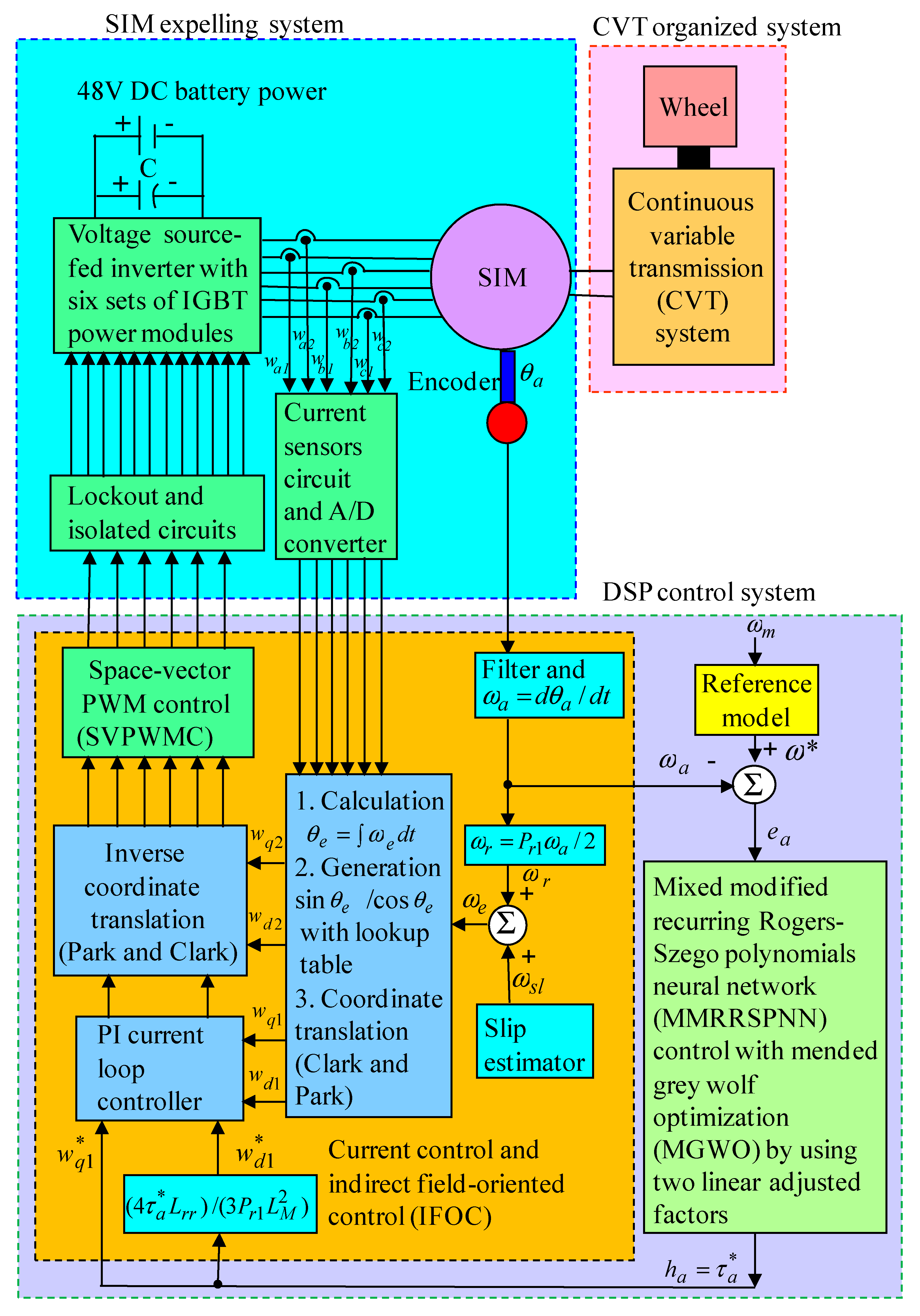
The conformation of the SIM expelling CVT organized system shown in Figure 2 includes three parts as the SIM expelling system, the CVT organized system, and the digital signal processor (DSP) control system. The CVT organized system consists of the wheel and the CVT system. The SIM expelling system consists of the current sensors and A/D converter, the interlock and isolated circuits, and the voltage source inverter with six sets of insulated-gate bipolar transistor (IGBT) power modules. The DSP control system can realize a space-vector pulse-width-modulation control (SVPWMC), an indirect-field-oriented control (IFOC), a proportional-integral (PI) current control loop, and a speed control loop. The IFOC consists of the sin θ e / cos θ e generation, the lookup table generation, and the coordinate translation. Two gains of the PI current controller are k p 1 = 18.6 and k i 1 = k p 1 / T i 1 = 7.6 by use of the Kronecker method to build a stability boundary in the k p 1 and k i 1 plane [44,45,46]. This method is used to narrow down the region for iterative selection of values of the parameters of k p 1 and k i 1 on the tuning of the PI controller so as to get fine dynamic response including some tests in an influence of time needed for electromagnetic torque shaping. The SIM expelling system was controlled by the DSP control system under aggregated parameter variations and aggregated nonlinear outward disturbances.

2.3. MMRRSPNN Control with MGWO by Using Two Adjusted Factors

For simplifying the control system design, the entire dynamic equation from (5) can be represented by
ω ˙ a = B c ω a / J c [ τ b l ( Δ τ 1 , Δ τ s , f l b ( v a b , τ a b , F b l , B b , ω b 2 ) ) + τ t ( τ l r , τ f r , τ c r , τ r r ) ] / J c + τ a / J c = Q a ω a + Q b τ w + Q c h a
where τ w = τ b l ( Δ τ 1 , Δ τ s , f l b ( v a b , τ a b , F b l , B b , ω b 2 ) ) + τ t ( τ l r , τ f r , τ c r , τ r r ) = Δ τ 1 + τ u 1 + Δ τ s + τ t ( τ l r , τ f r , τ c r , τ r r ) are the total disturbances. h a = τ a is the control intensity, i.e., the control torque of the SIM. Q a = B c / J c , Q c = 1 / J c and Q b = 1 / J c are three familiar constants. | Q a ω a | Z a ( ω a ) , | Q b τ w | Z b and Z c Q c are assumed to be bounded. Z a ( ω a ) is the bounded value of the function. Z b and Z c are assumed to be two familiar values. The speed discrepancy is defined by
e a = ω ω a
where e a is the speed discrepancy. When the aggregated parameter variations and the aggregated nonlinear outward disturbances are fine familiar, the intact control rule can be conceived by
h a = [ ω ˙ + k a e a Q a ω a Q b τ w ] / Q c
where k a > 0 is a positive constant. When h a = h a in (16) substituted into (14), then
e ˙ a + k a e a = 0
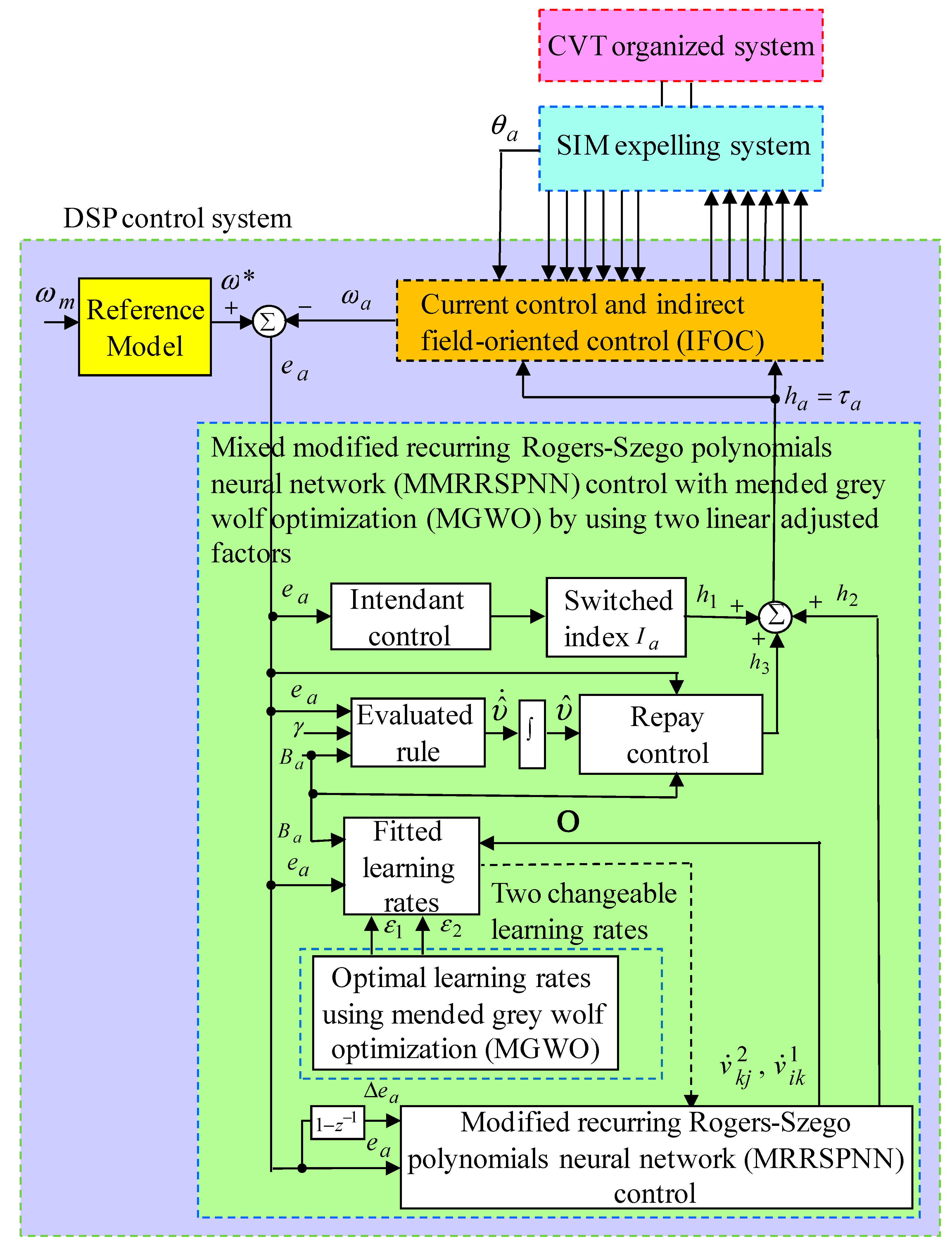
It is implied that the system’s state will track the desired trajectory when t and e a ( t ) 0 . In order to improve response of speed track under uncertainty action, the MMRRSPNN control with MGWO by using two adjusted factors was developed for controlling the SIM expelling CVT organized system. The control rule of the proposed control system depicted in Figure 3 is devised by
h a = h 1 + h 2 + h 3
where h 1 is the intendant control that can stabilize the system’s states on prescribed bound scope, h 2 is the MRRSPNN control that is the chief tracking controller, h 3 is the repay control that can compensate the error between the intact control rule and the MRRSPNN control.
From Equation (14) to Equation (18), a discrepancy dynamic equation can be represented by
e ˙ a = k a e a + [ h a h 1 h 2 h 3 ] Q c
Then, the intendant control h 1 can be represented by
h 1 = I a sgn ( e a Q c ) [ Z a ( ω a ) + Z b + | ω ˙ a | + | k a e a | ] / Q c
where sgn ( ) is a sign function. Besides, the sign function sgn ( Q c e a ) can be represented by the continuous function Q c e a / ( | Q c e a | + ς ) and ς = { ς 0   , 0   ,   | Q c e a | < ς | Q c e a | ς with ς 0 and ς are two small constants to reduce chattering in the intendant control. When the MRRSPNN approximation properties cannot be guaranteed, the intendant control rule that is effective has a switched index of one, i.e., I a = 1 . The MRRSPNN control rule is put forward to impersonate the intact control rule. Then the repay control rule is put forward to compensate the error between the intact control rule and the MRRSPNN control.
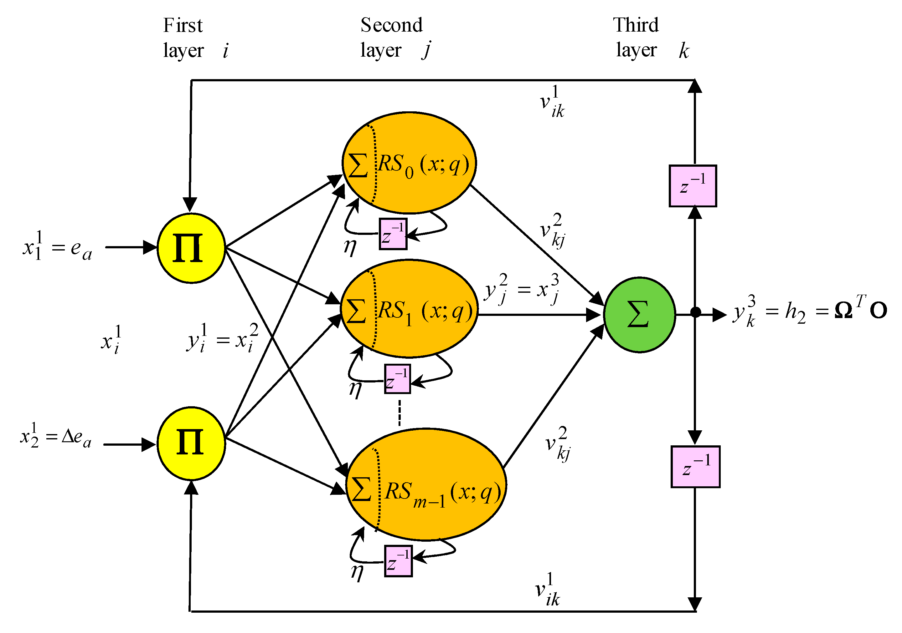
Further, the MRRSPNN with three-layer constitution composed of a first layer, a second layer, and a third layer, is pictured in Figure 4. The semaphore intentions in each node for each layer are explained in the following expression.
At the first layer, input semaphore and output semaphore are explained by
n e i 1 = k x i 1 ( R ) v i k 1 y k 3 ( R 1 ) , y i 1 = f i 1 ( n e i 1 ) = n e i 1 ,   i = 1 ,   2
where x 1 1 = ω ω a = e a and x 2 1 = e a ( 1 z 1 ) = Δ e a are the speed discrepancy and speed discrepancy alteration, respectively. R is the iteration count. v i k 1 is the recurring weight through the third layer and the first layer. y k 3 is the output of node at the third layer. The symbol Π is a multiply factor.
At the second layer, input semaphore and output semaphore are explained by
n e j       2 ( R ) = i = 1 2 y i 1 ( R ) + η   y j 2 ( R 1 ) ,     y j 2 = f j 2 ( n e j 2 ) = R S j ( n e j 2 ; q ) ,         j = 0 ,       1 ,       ,   m 1
where η is the recurring gain at the second layer. Rogers-Szego polynomials function [13,47] is adopted as the activation function. R S j ( x ; q ) is the Rogers-Szego polynomials function with 1 < x < 1 . R S 0 ( x ; q ) = 1 , R S 1 ( x ; q ) = 1 + x , and R S 2 ( x ; q ) = ( 1 + x ) ( 1 + x ) + x ( q 1 ) are the 0-, 1-, and 2-order Meixner polynomials functions, respectively. The first kind type of Rogers-Szego polynomials function at the recurrence relation [13,47] is given by R S n + 1 ( x ; q ) = ( 1 + x ) R S n ( x ; q ) + x ( q n 1 ) R S n 1 ( x ; q ) . The symbol is a summation factor.
At the third layer, semaphore and output semaphore are explained by
n e k   3 = j = 0 m 1 v k j 2 y j 2 ( R ) , y k 3 = f k 3 ( n e k 3 ) = n e k 3 ,   k = 1
where v k j 2 is the connective weight through the second layer and the third layer. f k 3 is the linear activation function. The output at the third layer can be rewritten by y k 3 ( R ) = h 2 . Therefore, the MRRSPNN controller can be represented by
y k 3 ( R ) = h 2 = Ω T O
where Ω = [ v 10 2 v 1 ,   m 1 2 ]     T and O = [ y 0 2 y m 1 2 ]   T are the weight vector at the third layer and the input vector at the third layer, respectively.
Moreover, a minimum discrepancy ρ in order to execute the repay control can be represented by
ρ = h a h 2 = h a ( Ω ) T O
where Ω is the intact weight vector and υ is a small positive number with | ρ | < υ . Equation (19) can be represented by
e ˙ a = k a e a + [ ( h a h 2 ) h 3 h 1 ] Q c = k a e a + [ ( h a h 2 + h 2 h 2 ) h 3 h 1 ] Q c = k c e c + [ ( h a h 2 ) + ( Ω ) T O Ω T O ) h 3 h 1 ] Q c = k a e a + [ ρ + ( Ω Ω ) T O h 3 h 1 ] Q c
So as to search for the adaptive rule of minimum discrepancy observer and adaptive rule of the MRRSPNN controller, the Lyapunov function then is represented by
H 1 = e a 2 / 2 + υ ˜ 2 / ( 2 γ ) + ( Ω Ω ) ( Ω Ω ) T / ( 2 ε 1 )
where γ > 0 is a fitted value. υ ˜ = υ ^ υ is the evaluated discrepancy. ε 1 is the learning rate. Then the Lyapunov function’s differential by means of Equations (25) and (26) can be represented by
H ˙ 1 = e ˙ a e a + υ ˜ υ ^ ˙ / γ ( Ω Ω ) T Ω ˙ / ε 1 = { k a e a + [ ρ + ( Ω Ω ) T O h 3 h 1 ] Q c } e a + υ ˜ υ ^ ˙ / γ ( Ω Ω ) T Ω ˙ / ε 1
For achieving H ˙ 1 0 , then the repay control h 3 , the evaluated rule υ ^ ˙ , and the fitted learning rule Ω ˙ can be devised by
Ω ˙ = ε   1   O Q c e a
h 3 = υ ^ sgn ( Q c e a )
υ ^ ˙ = γ | Q c e a |
The υ ^ will be observed by an adaptive observer and assumed to be bounded during the observation. The above assumption is valid in practical digital processing of the observer since the sampling period of the observer is short enough compared with the variation of ρ . If Equation (20) with I a = 0 , then Equation (28) by using Equations (29) and (30) can be represented by
H ˙ 1 = k a e a 2 + υ ˜ υ ^ ˙ / γ + ( ρ υ ^ sgn ( Q c e a ) ) Q c e a
Equation (32) by using Equation (31) and | ρ | < υ can be represented by
H ˙ 1 k a e a 2 + { | ρ | υ } | Q c e a | k a e a 2 0
It is a negative semi-definite for H ˙ 1 ( t ) in Equation (33), and then e a and ( Ω Ω ) are represented as bounded. Additionally, the uniformly continuous function ξ ( t ) can be defined by
ξ ( t ) = H ˙ 1 ( t ) = k a e a 2
Then take integration of Equation (34) as
0 t ξ ( τ ) d τ = 0 t   [ H ˙ 1 ( t ) ] d t = H 1 ( 0 ) H 1 ( t )
Since H 1 ( 0 ) and H 1 ( t ) are bounded, then
lim t 0 t ξ ( τ ) d τ <
Then take differential of Equation (34) as
ξ ˙ ( t ) = 2 k a e a e ˙ a
where e ˙ a is bounded at all variables of Equation (26) as bounded. By using Barbalat’s lemma [48,49] lim t ξ ( t ) = 0 , then e a ( t ) 0 as t . Furthermore, the sign function sgn ( Q c e a ) can be represented by the continuous function Q c e a / ( | Q c e a | + ς ) and ς = { ς 0   , 0   ,   | Q c e a | < ς | Q c e a | ς with ς 0 and ς are two small constants to reduce chattering in the countervailing controller.
A training means of parameters in the MRRSPNN can be unearthed by use of Lyapunov stability and the gradient descent skill. The MGWO by using two adjusted factors is applied to look for two better learning rates in the MRRSPNN to acquire faster convergence. The connecting weight parameter presented in Equation (29) can be represented by
v ˙ k j 2 = ε 1   x j 3   Q c e   a
An objective function that explains online training procedure of the MRRSPNN is defined by
H 2 = e a 2 / 2
The fitted learning rule of the connecting weight by use of the gradient descent skill with the chain rule is represented by
v ˙ k j 2 = ε 1 H 2 v k j 2 = ε 1 H 2 y k 3 y k 3 n e k 3 n e k 3 v k j 2 = ε 1 H 2 y k 3 x j 3
It is known that H 2 / y k 3 = e a Q c from Equation (38) and Equation (40). The fitted learning rule of recurring weight v i k 1 by use of the gradient descent technology with chain rule then is represented by
v ˙ i k 1 = ε 2   H 2   y k 3     y k 3   y j 2     y j 2   n e j 2     n e j 2   y i 1   y i 1   n e i 1       n e i 1   v i k 1 = ε 2   Q c   e a v k j 2 m j ( ) x i 1 ( N ) y k 3 ( N 1 )
where ε 2 is the learning rate. To acquire better convergence, the MGWO is applied to look for two changeable learning rates in the MRRSPNN. Besides, for improving convergence and finding two optimal learning rates, the MGWO by using two linear adjusted factors is proposed in this study.
In the MGWO with on-line data processing, the optimization is conducted by α , β , and δ . The MGWO algorithm can be denoted by
G ( l 1 + 1 ) = [ G 1 ( l 1 ) + G 2 ( l 1 ) + G 3 ( l 1 ) ] / 3
where G ( l 1 + 1 ) = [ ε 1   ε 2 ] is a vector that makes up two learning rates, G 1 ( l 1 ) ,   G 2 ( l 1 ) ,   G 3 ( l 1 ) are denoted by
G 1 ( l 1 ) = | α ( l 1 ) F 1 ( l 1 ) [ L 1 ( l 1 ) α ( l 1 ) G ( l 1 ) ] |
G 2 ( l 1 ) = | β ( l 1 ) F 2 ( l 1 ) [ L 2 ( l 1 ) β ( l 1 ) G ( l 1 ) ] |
G 3 ( l 1 ) = | δ ( l 1 ) F 3 ( l 1 ) [ L 3 ( l 1 ) δ ( l 1 ) G ( l 1 ) ] |
where α ( l 1 ) ,   β ( l 1 ) , δ ( l 1 ) are the three vectors as three best solutions; F 1 ( l 1 ) ,   F 2 ( l 1 ) ,   F 3 ( l 1 ) and L 1 ( l 1 ) ,   L 2 ( l 1 ) ,   L 3 ( l 1 ) are denoted by
F 1 ( l 1 ) = F 2 ( l 1 ) = F 3 ( l 1 ) = [ 2 a 1 ( l 1 ) b 1 ( l 1 ) ] φ 1
L 1 ( l 1 ) = L 2 ( l 1 ) = L 3 ( l 1 ) = 2 φ 2
where φ 1 and φ 2 are two random vectors. Two linear adjusted factors a 1 ( l 1 ) and b 1 ( l 1 ) , which due to their updated numbers control the tradeoff between exploration and exploitation, are linearly updated at each iteration according to the following presentation by
a 1 ( l 1 ) = 2 2 l 1 / I i t 1
b 1 ( l 1 ) = 2 2 l 1 / I i t 2
where l 1 is the iteration number; I i t 1 and I i t 2 are the total numbers of iteration allowed for the optimization. At last, G ( l 1 + 1 ) = [ ε 1   ε 2 ] is the best solution with regards to the learning rates ε l ( t ) ,   l = 1 ,   2 of the two weights in the MRRSPNN. Hence, the better numbers could be optimized by using MGWO yield two changeable learning rates for two weights to find two optimal values and to speed-up convergence of the two weights. The mode of calculations realized using MGWO is as follows: (1) initialization G ( l 1 ) = [ ε 1   ε 2 ] ; (2) Set the total numbers of iteration; (3) calculation of two linear adjusted factors a 1 ( l 1 ) = 2 2 l 1 / I i t 1 and b 1 ( l 1 ) = 2 2 l 1 / I i t 2 in Equations (48) and (49); (4) calculation two sets of three vectors F 1 ( l 1 ) ,   F 2 ( l 1 ) ,   F 3 ( l 1 ) and L 1 ( l 1 ) ,   L 2 ( l 1 ) ,   L 3 ( l 1 ) in Equations (46) and (47); (5) calculation three vectors G 1 ( l 1 ) ,   G 2 ( l 1 ) ,   G 3 ( l 1 ) in Equations (43)–(45); (6) calculation the best solution G ( l 1 + 1 ) = [ ε 1   ε 2 ] in Equations (43); (7) if NO, calculate l 1 = l 1 + 1 , then return to procedure; (3) if YES, go to the end of procedure.

3. Results

The conformation of the SIM expelling CVT organized system by using DSP control system is shown in Figure 2. The rated constitution of the CVT organized system are below as 648.2 mm for V-belt length, 73.6 mm for preceding pulley diameter, 32.3 mm for succeeding pulley diameter, 4.1 for conversion ratio. The rated format of the SIM is below as six-phase 48 V, 2 kW, 3068 r/min. The electrical and mechanical parameters of the SIM are below as r s = 2.96       Ω   , L s s = 19.38   m H , L r r = 19.32         m H , k a r = 0.202   N m / A , J a = 19.61 × 10 3   N m s , B a = 2.32 × 10 3 N m s / r a d . Because of inherent uncertainty in the CVT organized system (e.g., the aggregated parameter variations and the aggregated nonlinear outward disturbances) and current output limitation for DC power source, the SIM expelling CVT organized system is applied at 3000 r/min to avoid burning IGBT power modules. The flowchart of realized control methodologies with real-time implementation by means of DSP control system by using the “C” language in the experimental tests incorporates the principal program (PP) and the interrupt service routine (ISR), which is illustrated in Figure 5.
All input/output (I/O) initialization and parameters are first processed in the PP and then the interrupt time in the ISR is set. The ISR with 2 msec sampling time is applied for reading six-phase currents from A/D converters and rotor position of the SIM expelling CVT organized system from encoder, calculating rotor position and speed, executing lookup table and coordinate transformation, executing PI current control, executing the proposed MMRRSPNN control with MGWO by using two linear adjusted factors, and outputting six-phase SVPWMC signals to drive the IGBT power module voltage source inverter. Two judger g1 and g1_mx shown in the flowchart are provided to realize the IFOC. The judger g2 is provided to realize the proposed control scheme by DSP control system. Two initial values g1 and g2 are set to zero. The initial value g1_mx is set to three. When the IFOC is implemented less three times, i.e., g1 < g1_mx, the IFOC must be continuously realized. Then this process will go back to the primary start. Therefore, the IFOC will execute three times, then the proposed control scheme realized by DSP control system will execute one time. The voltage source inverter with six-sets of IGBT power modules is executed by a six-phase SVPWMC. In addition, the measured bandwidth of position control loop is about 0.1 kHz and the measured bandwidth of current control loop is about 1 kHz. So as to enhance precision of the sampling signals from A/D converter, the sampling interval of the control processing in the tested results is set at 1 msec (1 kHz) so that the DSP control system has enough time to process the control algorithm. Because of inherent uncertainty in the SIM expelling CVT organized system, current output limitation and voltage output limitation for DC bus power, the DC bus power only operated under maximum current, and maximum voltage for avoiding burning down the IGBT power modules for the SIM expelling CVT organized system. Furthermore, so as to prevent over-load operation and the voltage source inverter burn, the SIM expelling CVT organized system displayed in Figure 2 has six sets of over current protection circuits, six sets of over voltage protection circuits, and six sets of under voltage protection circuits.
Some experimental results with two tests are demonstrated to show various control performances. The one aggregated parameter variations and aggregated nonlinear outward disturbances Δ τ 1 + τ u 1 + Δ τ s case at 1500 r/min is the tested Event E1 case. The double aggregated parameter variations and aggregated nonlinear outward disturbances Δ τ 1 + τ u 1 + Δ τ s case at 3000 r/min is the tested Event E2 case. Besides, for comparison control performance by using the celebrated PI controller as the controller CT1, the MRRHPNN control system with mend ACO [37] as the controller CT2 and the proposed wise dynamic control system using MMRRSPNN control and MGWO with two adjusted factors as the controller CT3 are adopted in this study.
To get good transient-state and steady-state control performance, two gains of the celebrated PI controller as the controller CT1 are k p 2 = 18.6 , k i 2 = k p 2 / T i 2 = 4.3 by use of the Kronecker method to build a stability boundary in the k p 2 and k i 2 plane [44,45,46]. This method is used to narrow down the region for iterative selection of values of the parameters of k p 2 and k i 2 on the tuning of the PI controller with one aggregated parameter variations and aggregated nonlinear outward disturbances Δ τ 1 + τ u 1 + Δ τ s case at 1500 r/min for the speed tracking.
The MRRHPNN control system with mend ACO as the controller CT2 adopted 2, 3, and 1 nodes in the first, second, and third layers for the RRHPNN, respectively. Moreover, all gains are set to achieve better transient control performance in tests considering the requirement of stability. Besides, the control gains of the MRRHPNN control system with mend ACO are given by k a = 3.6 ,     η = 0.10 ,     γ = 0.21 with one aggregated parameter variations and aggregated nonlinear outward disturbances Δ τ 1 + τ u 1 + Δ τ s case at 1500 r/min for the speed tracking. The parameter adjustment process remains continually active for the duration of the experimentation. The parameter’s initialization of the MRRSPNN in Lewis et al. [50] is adopted to initialize the parameters in this paper. The parameter adjustment process remains continually active for the duration of the experimentation.
The proposed MMRRSPNN control with MGWO by using two linear adjusted factors as the controller CT3 adopted 2, 3, and 1 nodes in the first, second, and third layers for the MRRSPNN, respectively. Besides, all gains are set to achieve better transient control performance in experimentation considering the requirement of stability. Furthermore, the control gains of the MMRRSPNN control with MGWO by using two linear adjusted factors are given by k a = 3.6 ,     η = 0.10 ,     γ = 0.21 with one aggregated parameter variations and aggregated nonlinear outward disturbances Δ τ 1 + τ u 1 + Δ τ s case at 1500 r/min for the speed tracking. The parameters adjustment process remains continually active for the duration of the experimentation. The parameter’s initialization of the MRRSPNN in Lewis et al. [50] is adopted to initialize the parameters in this paper. The parameter adjustment process remains continually active for the duration of the experimentation.
Firstly, the tested results for the SIM expelling CVT organized system by using the celebrated PI controller as the controller CT1 at the tested Event E1 case and at the tested Event E2 case are demonstrated in Figure 6, Figure 7 and Figure 8.
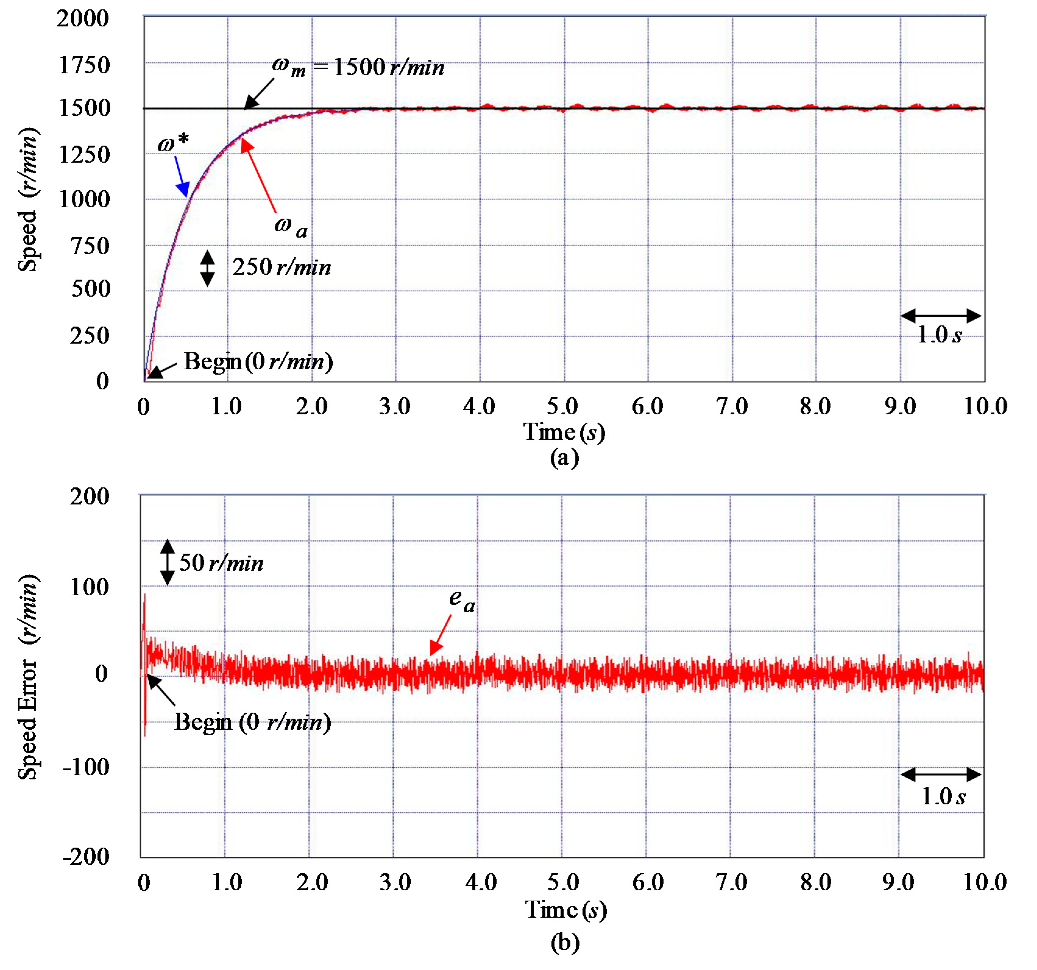
Figure 6a and Figure 7a demonstrate the speed responses in the command speed ω m , reference model speed ω , and measured speed ω a . Figure 6b and Figure 7b demonstrate the speed discrepancy e a responses. Figure 8a,b demonstrate the developed torque τ a responses. Good speed tracking performance at the tested Event E1 case shown in Figure 6a is due to small disturbances which is the same as the rated case. Besides, the developed torque τ a response shown in Figure 8a,b guides to large torque ripple due to the CVT system’s push-pull friction. The tested results show that tardy speed responses demonstrated in Figure 7a was obtained by using the controller CT1 due to unfit gains tuning.
Secondly, the tested results of the MRRHPNN control system with mend ACO [37] as the controller CT2 for the SIM expelling CVT organized system at the tested Event E1 case and at the tested Event E2 case are demonstrated in Figure 9, Figure 10 and Figure 11.
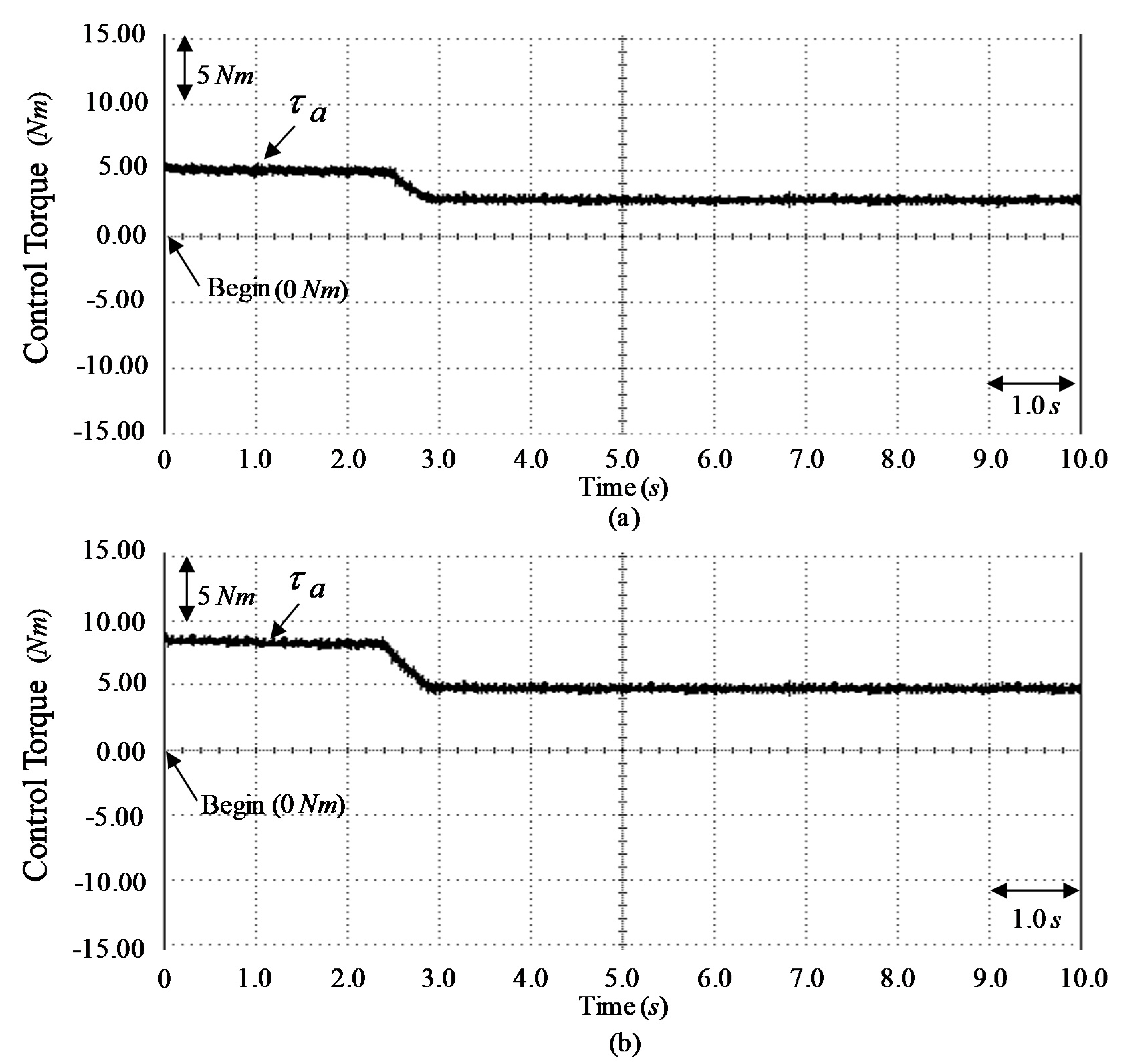
Figure 9a and Figure 10a demonstrate the speed responses of measured speed ω a , reference model speed ω and command speed ω m . Figure 9b and Figure 10b demonstrate the speed discrepancy e a responses. Figure 11a,b demonstrate the developed torque τ a responses. Figure 9a demonstrates good performance of speed tracking at the tested Event E1 case due to small disturbances which is the same as the rated case. Good response of speed tracking is demonstrated in Figure 10a at the tested Event E2 case. The tested results demonstrate that good tracking performance was achieved for the SIM expelling CVT organized system by use of the controller CT2 due to the online changeable method of the MRRHPNN control system and the compensated controller action.
Thirdly, the tested results of the wise dynamic control system using MMRRSPNN control and MGWO with two adjusted factors as the controller CT3 for the SIM expelling CVT organized system at the tested Event E1 case and at the tested Event E2 case are demonstrated in Figure 12, Figure 13 and Figure 14.
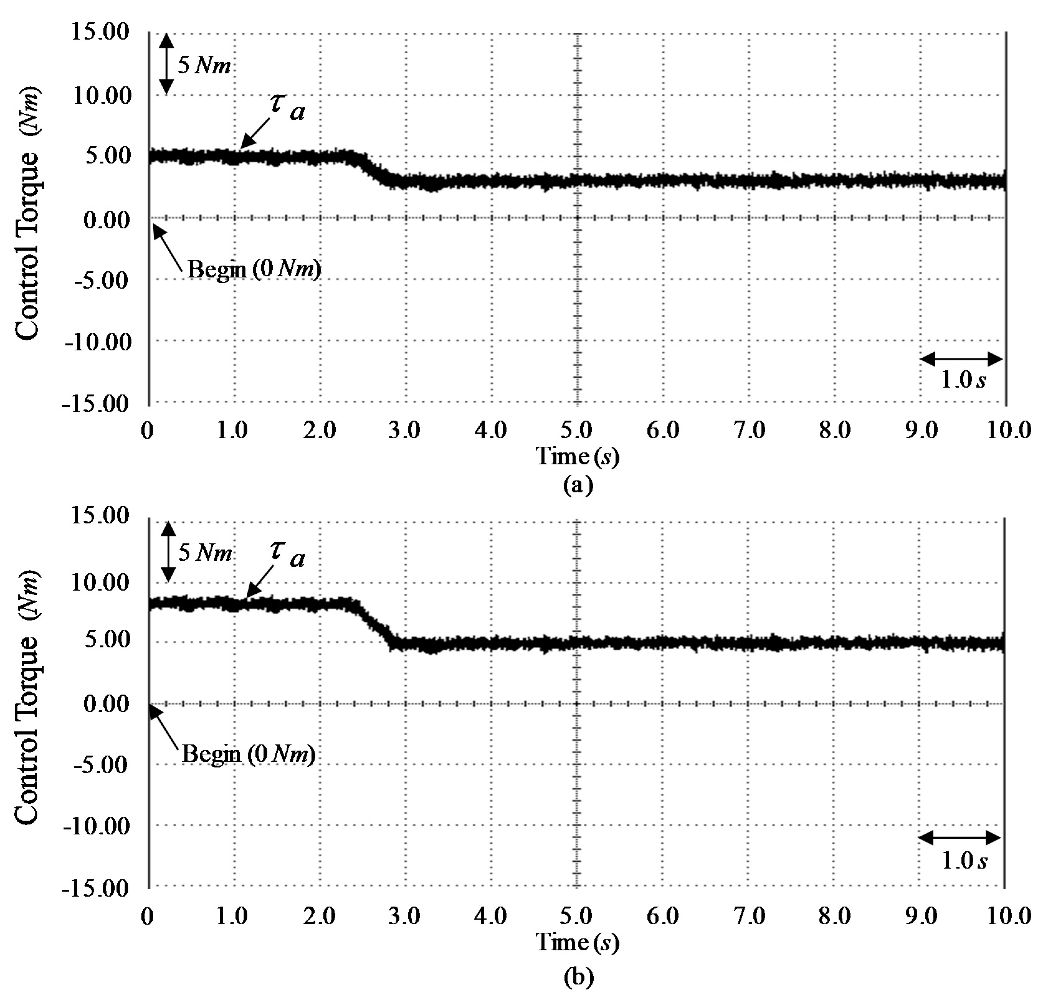
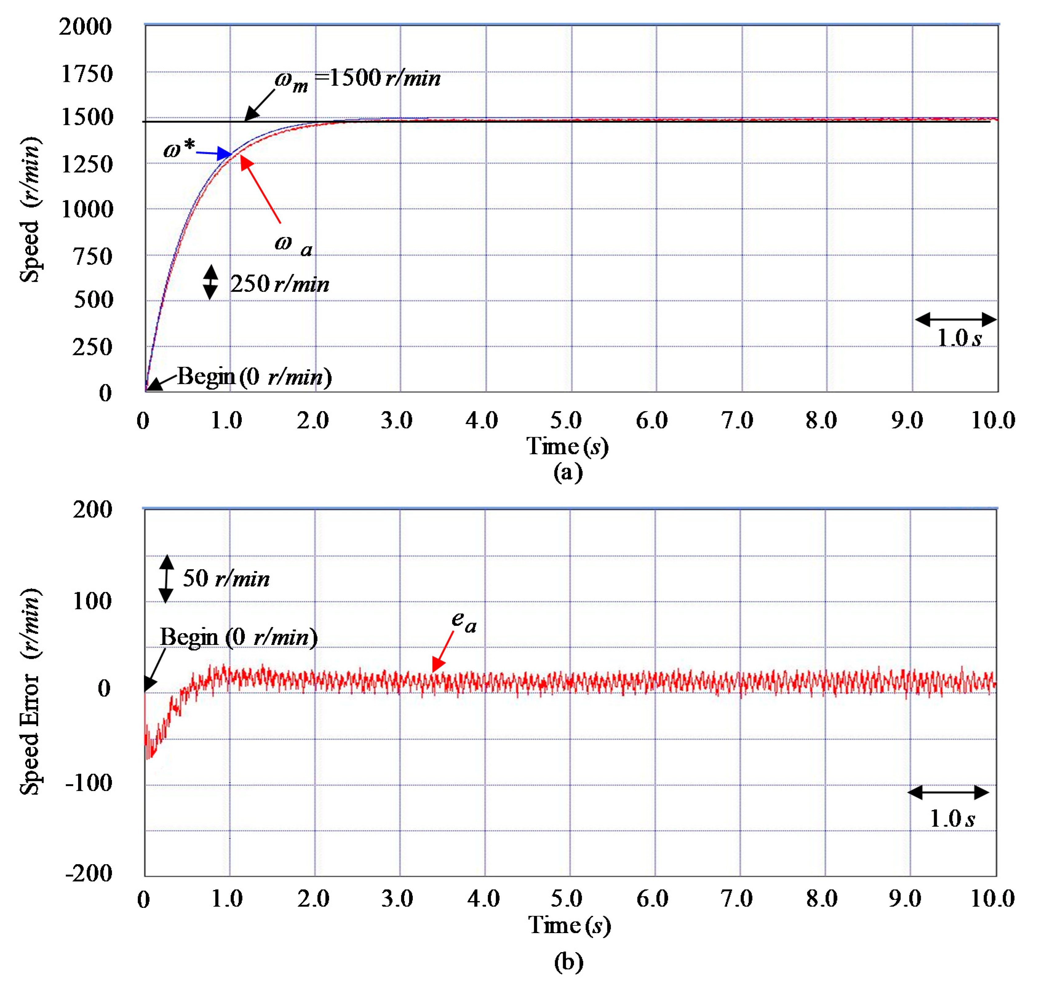
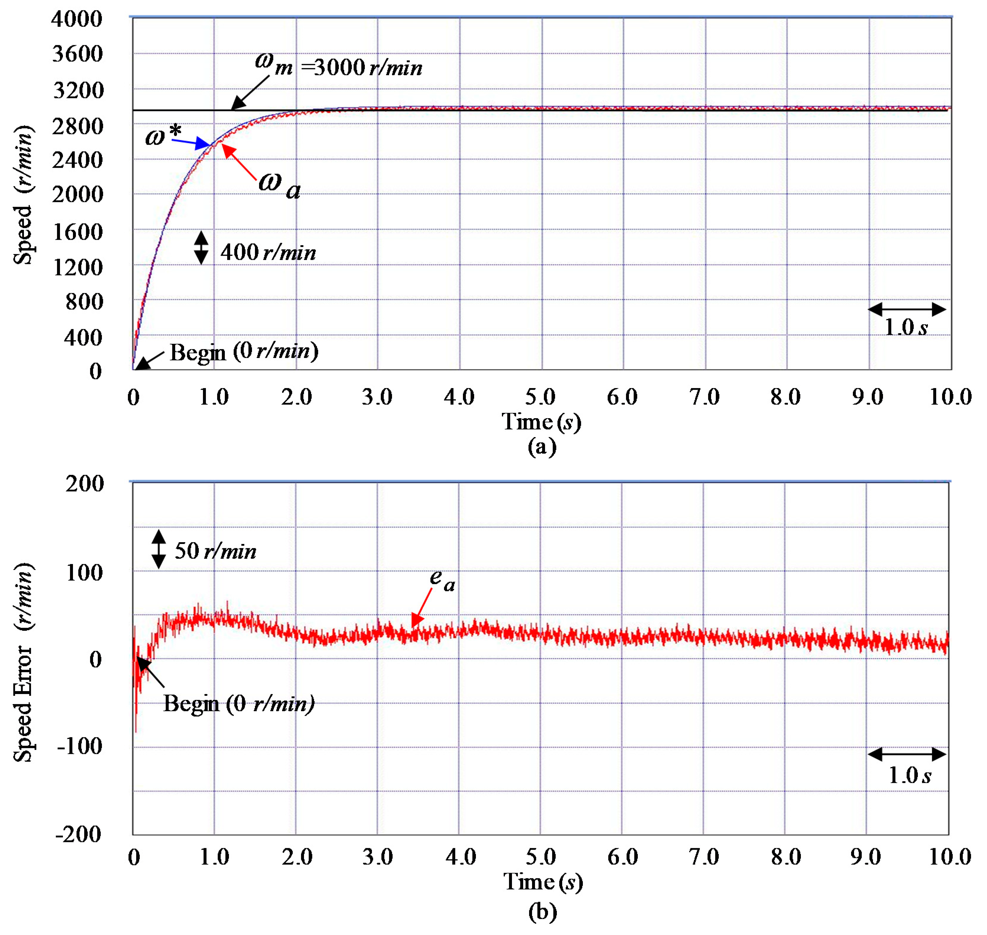
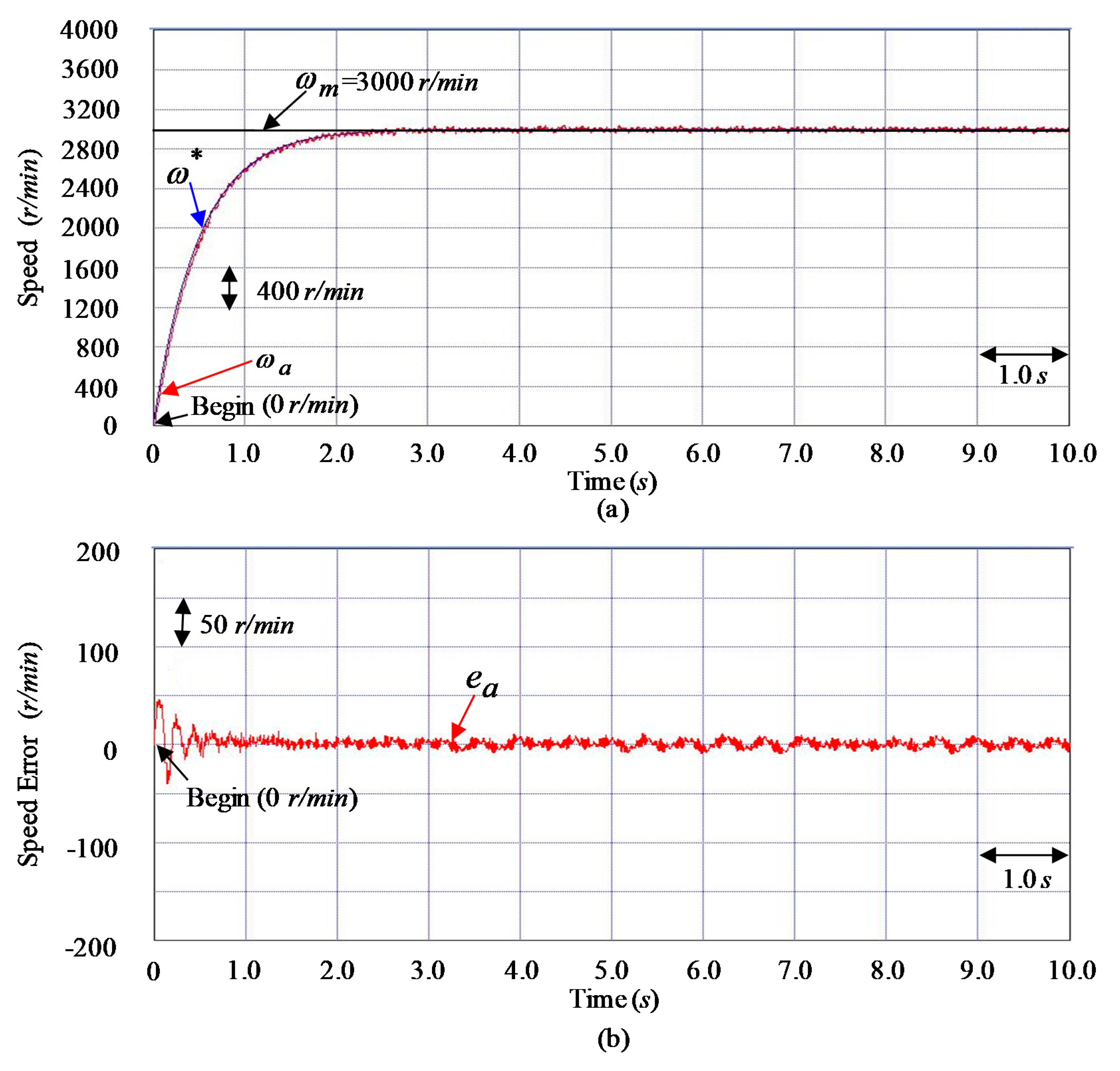
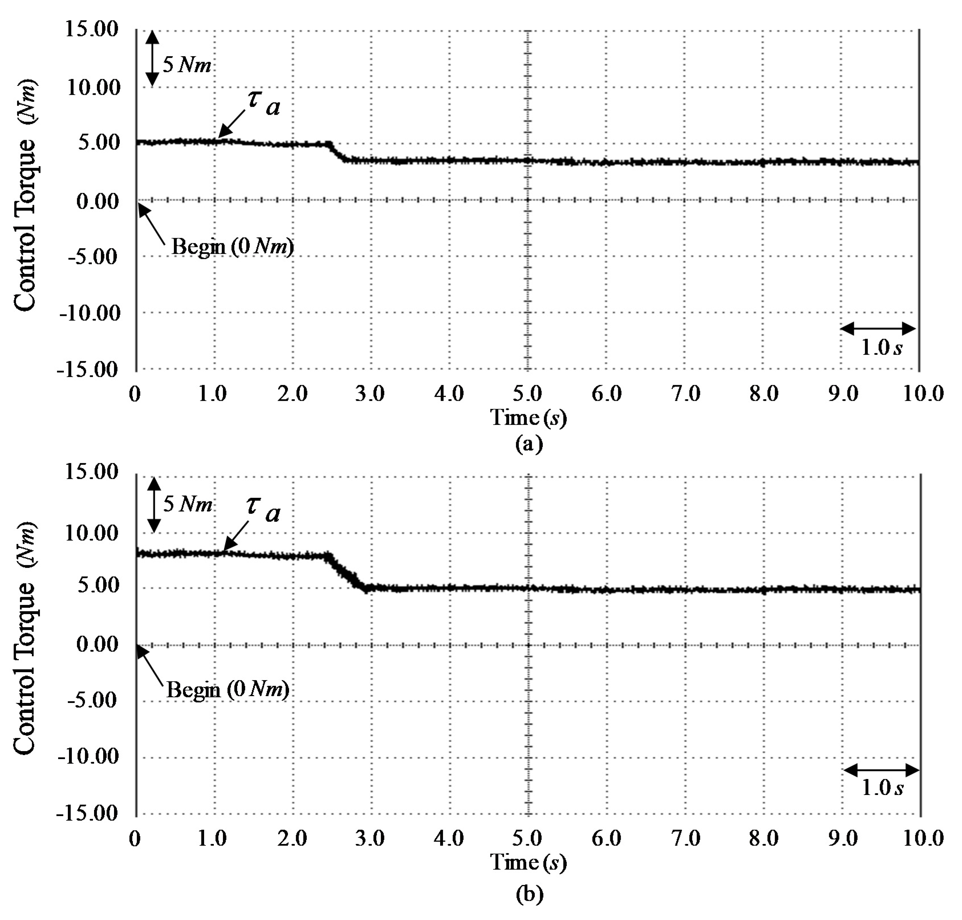
Figure 12a and Figure 13a demonstrate the speed responses of measured speed ω a , reference model speed ω , and command speed ω m . Figure 12b and Figure 13b demonstrate the speed discrepancy e a responses. Figure 14a,b demonstrate the responses of developed torque τ a . Figure 12a demonstrates better performance of speed tracking at the tested Event E1 case because it is the same as the nominal case with smallest disturbances. The higher speed tracking response is demonstrated in Figure 13a at the tested Event E2 case. The tested results show that a more accurate tracking performance was achieved for the SIM expelling CVT organized system when the controller CT3 was used because of the online fitted mechanism of the MRRSPNN and the repay controller action. The developed torque τ a response shown in Figure 14a,b demonstrates lower torque ripple by online adjustment of the MRRSPNN control system and MGWO with two adjusted factors to process the unmodeled dynamic of a CVT organized system such as push-pull frictions.
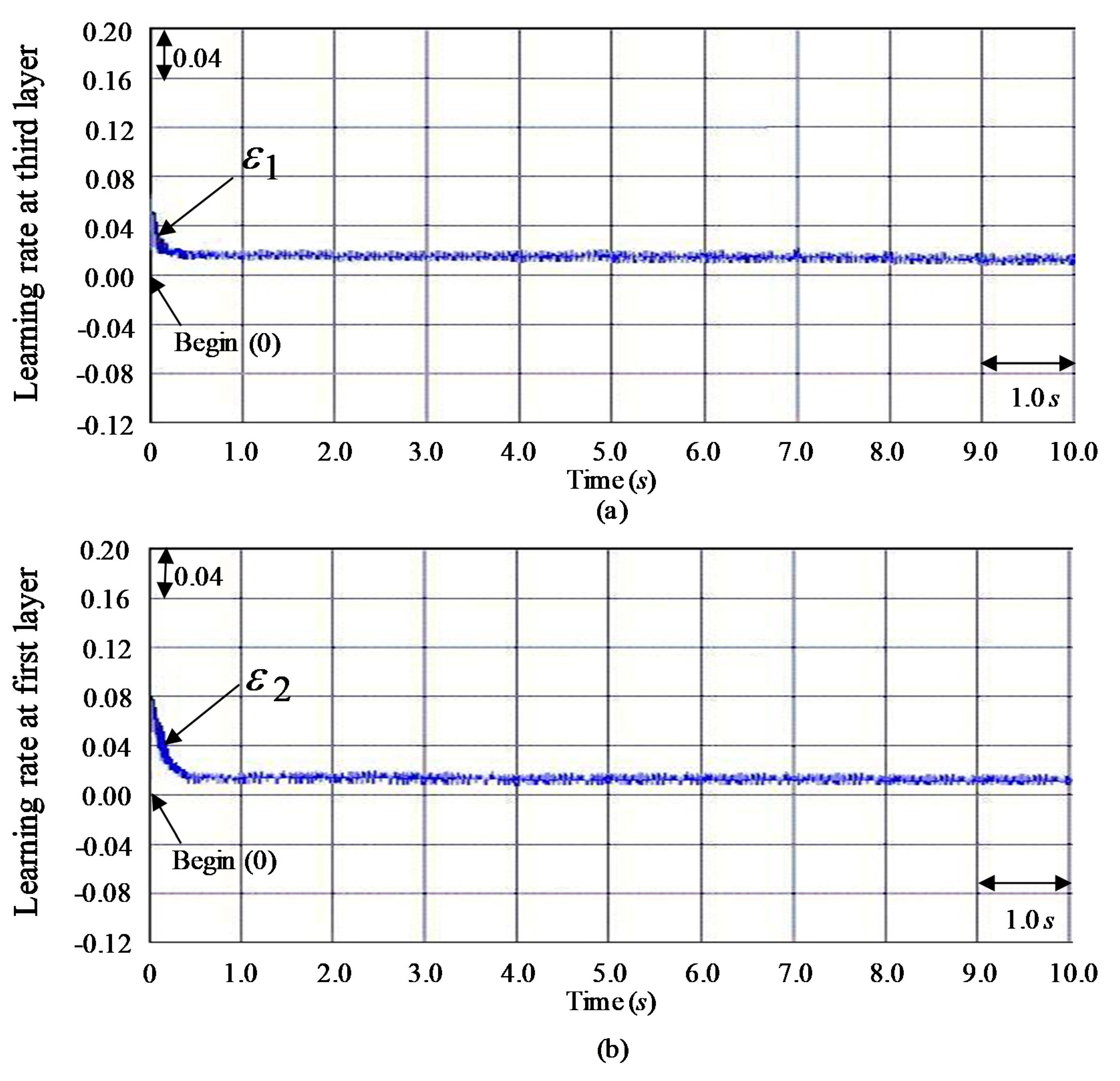
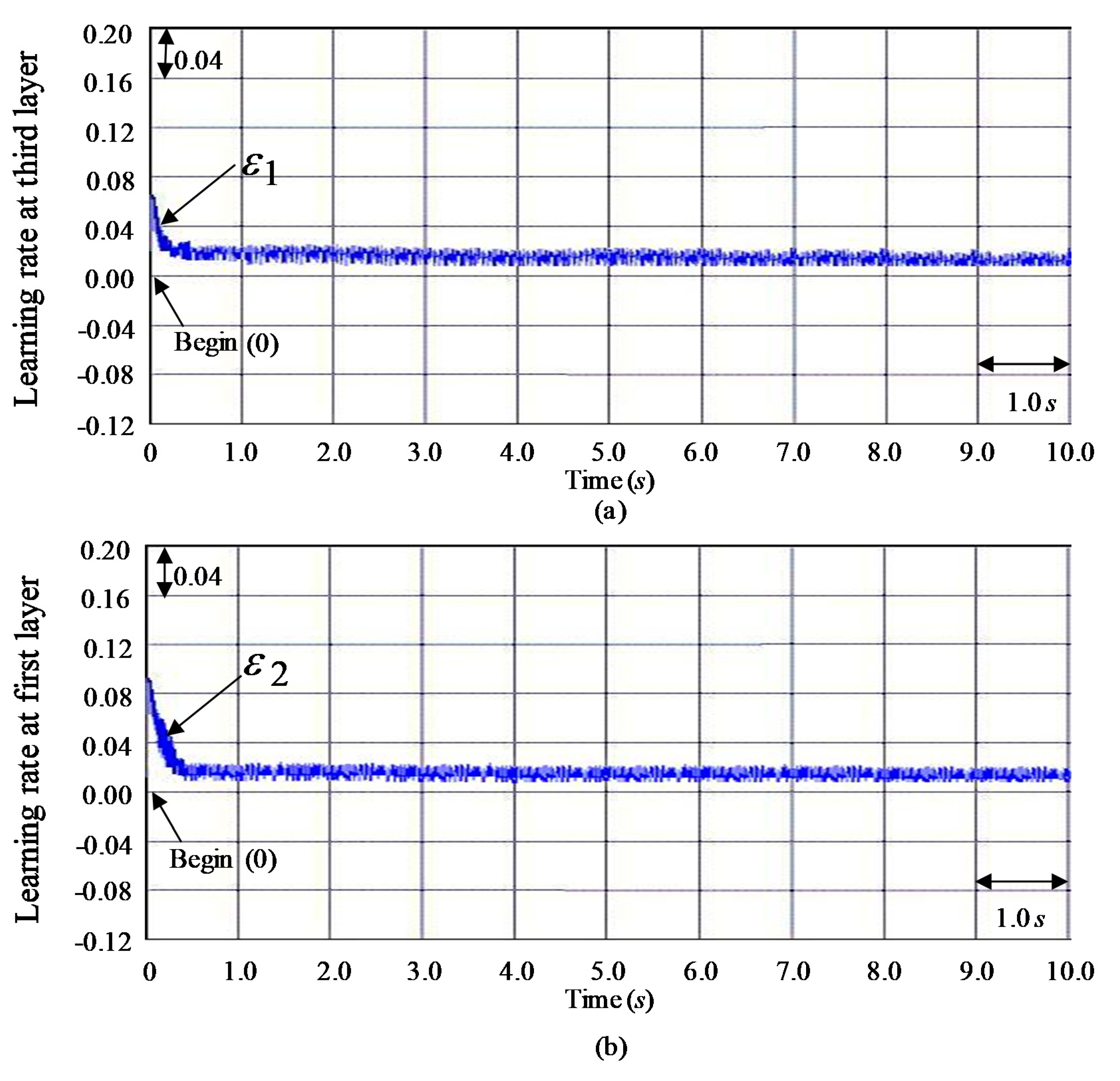
Besides, Figure 15a,b demonstrate the convergent speeds of two learning rates ε 1 and ε 2 in the MRRSPNN using MGWO with two adjusted factors at the tested Event E1 case, respectively. Figure 16a,b demonstrate the convergent speeds of two learning rates ε 1 and ε 2 in the MRRSPNN using MGWO with two adjusted factors at the tested Event E2 case, respectively.
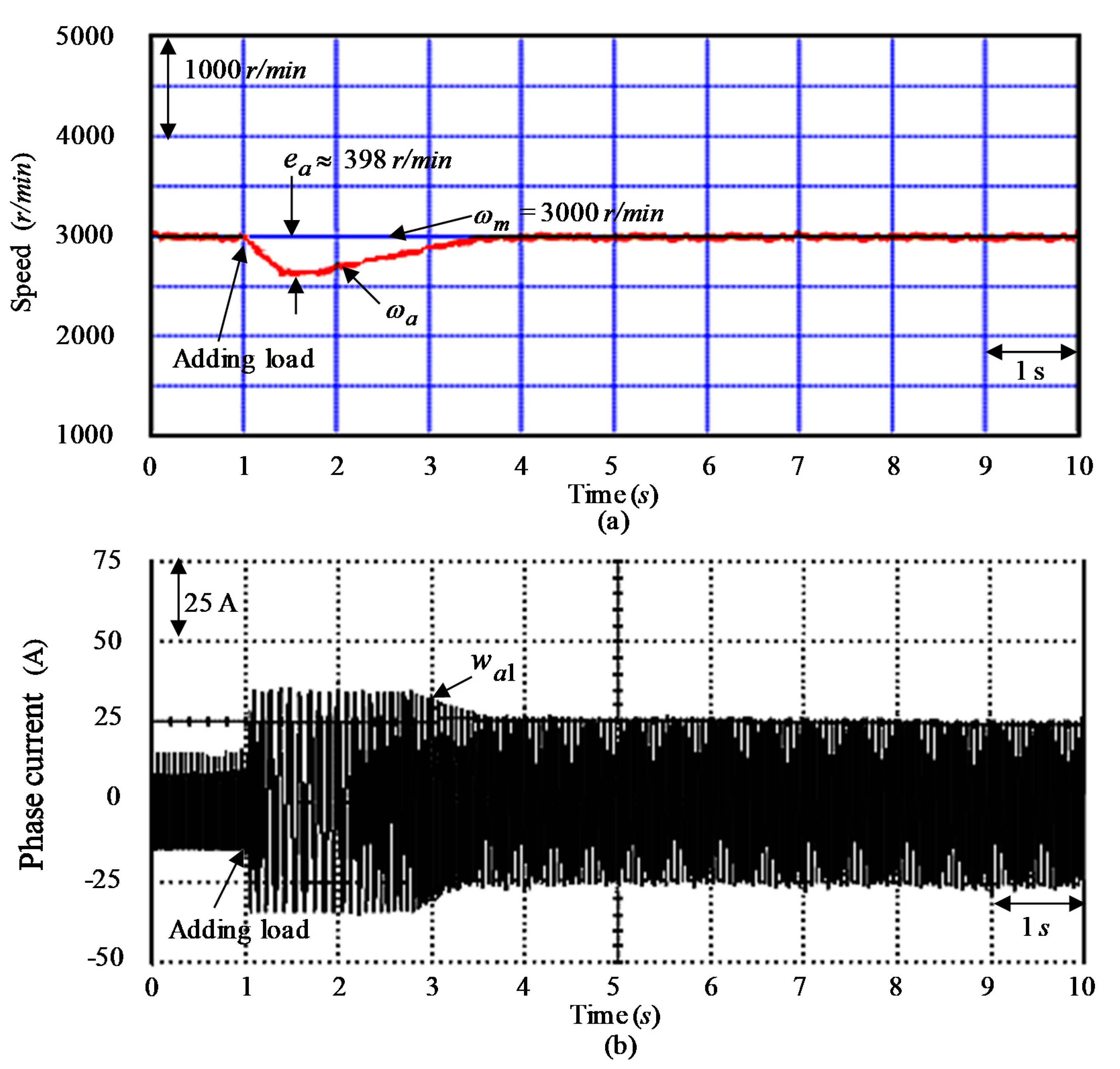
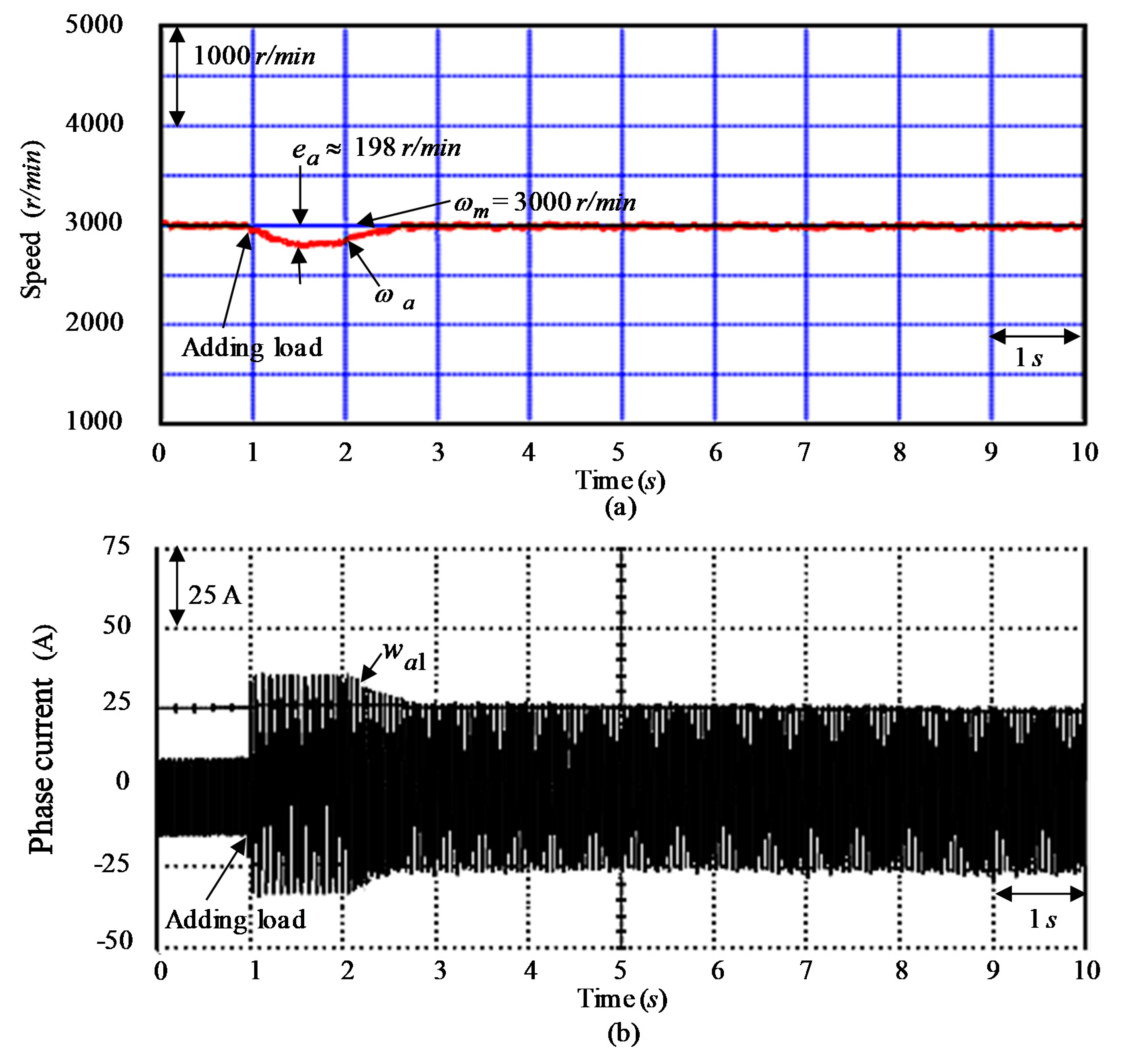
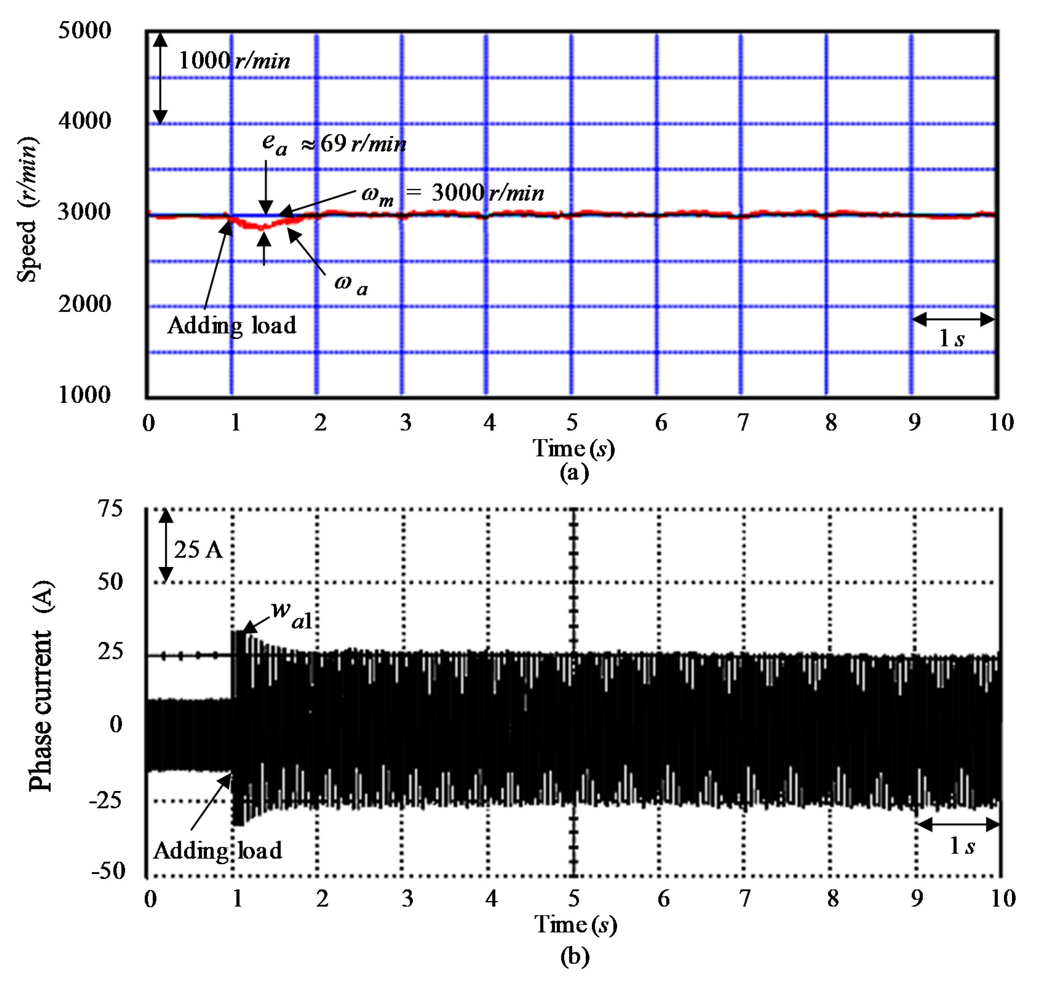
Finally, rotor speed responses under adding load torque disturbance and aggregated nonlinear outward disturbances 2 N m ( τ t ) + τ u 1 + Δ τ s at 3000 r/min speed as the tested Event E3 case is tested by using the controller CT1, the controller CT2 and the controller CT3. Figure 17, Figure 18 and Figure 19 demonstrate the tested results of speed and current w a 1 in phase a at the tested Event E3 case when the controller CT1, the controller CT2, and the controller CT3 were used, respectively. Figure 17a, Figure 18a, and Figure 19a demonstrate speed-adjusted response of the command speed ω m and measured speed ω a at the tested Event E3 case when the controller CT1, the controller CT2, and the controller CT3 were used, respectively. Figure 17b, Figure 18b, and Figure 19b demonstrate the measured current w a 1 in phase a at the tested Event E3 case when the controller CT1, the controller CT2, and the controller CT3 were used, respectively. The tested results demonstrate that the degenerated responses at the tested Event E3 case are considerably improved when the controller CT3 was used.
Besides, transient response of the controller CT3 demonstrates better convergence and fine load regulation than the controller CT1 and the controller CT2.

4. Discussion

Furthermore, a control performance comparison of the the celebrated PI controller as the controller CT1, The MRRHPNN control system with mend ACO as the controller CT2, and the proposed MMRRSPNN control with MGWO by using two adjusted factors as the controller CT3 is presented in Table 1 for experimental results of three test cases. The maximum errors of e a by utilized the control systems CT1, CT2, and CT3 at tested Event E1 case are 88 r/min, 69 r/min and 40 r/min, respectively. The root mean square errors of e a by utilized the control systems CT1, CT2, and CT3 at tested Event E1 case are 45 r/min, 30 r/min, and 20 r/min, respectively. The maximum errors of e a by utilized the control systems CT1, CT2, and CT3 at tested Event E2 case are 215 r/min, 88 r/min, and 43 r/min, respectively. The root mean square errors of e a by utilized the control systems CT1, CT2, and CT3 at tested Event E2 case are 60 r/min, 31 r/min, and 22 r/min, respectively. The maximum errors of e a by utilized the control systems CT1, CT2, and CT3 at tested Event E3 case are 398 r/min, 198 r/min, and 69 r/min, respectively. The root mean square errors of e a by utilized the control systems CT1, CT2, and CT3 at tested Event E3 case are 51 r/min, 27 r/min, and 17 r/min, respectively. As shown in Table 1, the control systems CT3 results in smaller tracking error in comparison with the control systems CT1 and CT2. According to the tabulated measurements, the control systems CT3 indeed yields the superior control performance.
Furthermore, the characteristic performance comparisons of the control systems CT1, CT2, and CT3 are gathered up in Table 2 from tested results. In Table 2, some performances with regards to the control rule with vibration, the dynamic response, the regulation ability of load torque disturbance, the convergent speed, the speed tracking error, the rejection ability of parameter disturbance, and torque ripple (V-belt shaking action and torsional vibration variations) in the control systems CT3 are superior to the control systems CT1 and CT2.

5. Conclusions

The MMRRSPNN control with MGWO by using two adjusted factors has been favorably used for controlling the SIM expelling CVT organized system with good robustness. The MMRRSPNN control with MGWO by using two linear adjusted factors, which can execute intendant control system, MRRSPNN control, and the repay control, was put forward to decrease and sleek the control intensity when the system’s states are within the specified bound range. The primary contributions of this study are as follows: (a) the simplified dynamic models of the CVT expelled by the SCRIM with nonlinear uncertainties were smoothly originated; (b) the MMRRSPNN control system was well employed for the SIM expelling CVT organized system under intact nonlinear outward disturbances to improve robustness; (c) the fitted learning rule in the MRRSPNN control and the evaluated rule in the repay control were successfully established by use of the Lyapunov stability theorem; (d) the MGWO by using two adjusted factors was well used for changing two varied learning rates of connective and recurring weights in the MRRSPNN to achieve good convergence; and (e) the MMRRSPNN control with MGWO by using two linear adjusted factors as the controller CT3 is superior than the celebrated PI controller as the controller CT1 and the MRRHPNN control system with mend ACO [37] as the controller CT2 in torque ripple reduction.
Finally, the controller CT3 is superior to the controller CT1 and the controller CT2 from all tested results and control performances for the SIM expelling CVT organized system.
Future related works are as follows: (a) the development of the detailed modelling in the entire models of CVT organized system; (b) the use of the more superior DSP control systems to reduce realized time; (c) the combination with more advanced control system to enhance the robustness of systems; (d) the program of the control structure for other (square) reference trajectory.

Author Contributions

D.-F.C. and J.-C.T. conceived and designed the system and experiments; Y.-C.S. and S.-C.L. performed the software programs and the experimental tests; C.-T.C. and J.-C.T. analyzed the data for writing the paper; D.-F.C. and J.-C.T. revised the paper. All authors have read and agreed to the published version of the manuscript.

Funding

This research received no external funding.

Conflicts of Interest

The authors declare no conflict of interest.

References

  1. Heydar, M.; Milad, S.; Mohammad, H.A.; Ravinder, K.; Shahaboddin, S. Modeling and efficiency optimization of steam boilers by employing neural networks and response-surface method (RSM). Mathematics 2019, 7, 629. [Google Scholar]
  2. Shao, Y.E.; Lin, S.C. Using a time delay neural network approach to diagnose the out-of-control signals for a multivariate normal process with variance shifts. Mathematics 2019, 7, 959. [Google Scholar] [CrossRef] [Green Version]
  3. Behzad, M.; Mahyar, G.; Mohammad, H.A.; Heydar, M.; Shahabddin, S. Moisture estimation in cabinet dryers with thin-layer relationships using a genetic algorithm and neural network. Mathematics 2019, 7, 1042. [Google Scholar]
  4. Shih, P.C.; Chiu, C.Y.; Chou, C.H. Using dynamic adjusting NGHS-ANN for predicting the recidivism rate of commuted prisoners. Mathematics 2019, 7, 1187. [Google Scholar] [CrossRef] [Green Version]
  5. Nagamani, G.; Ramasamy, S. Stochastic dissipativity and passivity analysis for discrete-time neural networks with probabilistic time-varying delays in the leakage term. Appl. Math. Comput. 2016, 289, 237–257. [Google Scholar] [CrossRef]
  6. Nagamani, G.; Ramasamy, S. Dissipativity and passivity analysis for discrete-time T–S fuzzy stochastic neural networks with leakage time-varying delays based on Abel lemma approach. J. Frankl. Inst. 2016, 353, 3313–3342. [Google Scholar] [CrossRef]
  7. Nagamani, G.; Ramasamy, S.; Mey-Base, A. Robust dissipativity and passivity based state estimation for discrete-time stochastic Markov jump neural networks with discrete and distributed time-varying delays. Neural Comput. Appl. 2017, 28, 717–735. [Google Scholar] [CrossRef]
  8. Ramasamy, S.; Nagamani, G.; Radhika, T. Further results on dissipativity criterion for markovian jump discrete-time neural networks with two delay components via discrete wirtinger inequality approach. Neural Process. Lett. 2017, 45, 939–965. [Google Scholar] [CrossRef]
  9. Lee, T.T.; Jeng, J.T. The Chebyshev polynomial-based unified model neural networks for functional approximation. IEEE Trans. Syst. Man Cybern. Part B 1998, 28, 925–935. [Google Scholar]
  10. Lin, C.H. Composite Recurring Laguerre orthogonal polynomials neural network dynamic control for continuously variable transmission system using altered particle swarm optimization. Nonlinear Dyn. 2015, 81, 1219–1245. [Google Scholar] [CrossRef]
  11. Lin, C.H. Comparative dynamic control for continuously variable transmission with nonlinear uncertainty using blend amend recurring Gegenbauer-functional-expansions neural network. Nonlinear Dyn. 2017, 87, 1467–1493. [Google Scholar] [CrossRef]
  12. Ting, J.C.; Chen, D.F. Nonlinear backstepping control of SynRM drive systems using reformed recurring Hermite polynomial neural networks with adaptive law and error estimated law. J. Power Electron. 2018, 8, 1380–1397. [Google Scholar]
  13. Szego, G. Beitrag zur theorie der thetafunktionen. Sitz Preuss. Akad. Wiss. Phys. Math. Ki. 1926, 19, 242–252. [Google Scholar]
  14. Cirovic, V.; Aleksendric, D.; Mladenovic, D. Braking torque control using recurring neural networks. Proc. Inst. Mech. Eng. Part D J. Automob. Eng. 2012, 226, 754–766. [Google Scholar] [CrossRef]
  15. Wong, W.C.; Chee, E.; Li, J.; Wang, X. Recurring neural network-based model predictive control for continuous pharmaceutical manufacturing. Mathematics 2018, 6, 242. [Google Scholar] [CrossRef] [Green Version]
  16. Ting, J.C.; Chen, D.F. Novel mingled reformed recurring hermite polynomial neural network control system applied in continuously variable transmission system. J. Mech. Sci. Technol. 2018, 32, 4399–4412. [Google Scholar] [CrossRef]
  17. Lin, C.H.; Chang, K.T. Admixed recurring Gegenbauer polynomials neural network with mended particle swarm optimization control system for synchronous reluctance motor driving continuously variable transmission system. Proc. Inst. Mech. Eng. Part I J. Syst. Control Eng. 2020, 234, 183–198. [Google Scholar]
  18. Liu, C.; Huang, B.; Wang, Q. Control performance assessment subject to multi-objective user- specified performance characteristics. IEEE Trans. Control Syst. Technol. 2011, 19, 682–691. [Google Scholar] [CrossRef]
  19. Cano-Izquierdo, J.M.; Ibarrola, J.; Kroeger, M. Control loop performance assessment with a dynamic neuro-fuzzy model (dFasArt). IEEE Trans. Autom. Sci. Eng. 2012, 9, 377–389. [Google Scholar] [CrossRef]
  20. Kordestani, M.; Safavi, A.A.; Sharafi, N.; Saif, M. Novel multiagent model-predictive control performance indices for monitoring of a large-scale distributed water system. IEEE Syst. J. 2018, 12, 1286–1294. [Google Scholar] [CrossRef]
  21. Kordestani, M.; Safavi, A.A.; Sharafi, N.; Saif, M. Fault tolerant control of Rhine-Meuse delta water system: A performance assessment based approach. In Proceedings of the International Conference on Power Generation Systems and Renewable Energy Technologies (PGSRET), Istanbul, Turkey, 26–27 August 2019; pp. 31–38. [Google Scholar]
  22. Emary, E.; Yamany, W.; Hassanien, A.E. Multi-objective gray-wolf optimization for attribute reduction. Procedia Comput. Sci. 2015, 1, 623–632. [Google Scholar] [CrossRef] [Green Version]
  23. Mosavi, M.; Khishe, M.; Ghamgosar, A. Classification of sonar data set using neural network trained by gray wolf optimization. Neural Netw. World 2016, 26, 393–415. [Google Scholar] [CrossRef] [Green Version]
  24. Khandelwal, A.; Bhargava, A.; Sharma, A.; Sharma, H. Modified grey wolf optimization algorithm for transmission network expansion planning problem. Arabian J. Sci. Eng. 2018, 43, 2899–2908. [Google Scholar] [CrossRef]
  25. Mirjalili, S.; Mirjalili, S.M.; Lewis, A. Grey wolf optimizer. Adv. Eng. Softw. 2014, 69, 46–61. [Google Scholar] [CrossRef] [Green Version]
  26. Sultana, U.; Khairuddin, A.B.; Mokhtar, A.S. Grey wolf optimizer based placement and sizing of multiple distributed generation in the distribution system. Energy 2016, 111, 525–536. [Google Scholar] [CrossRef]
  27. Parsian, A.; Ramezani, M.; Ghadimi, N. A hybrid neural network-gray wolf optimization algorithm for melanoma detection. Biomed. Res. 2017, 28, 3408–3411. [Google Scholar]
  28. Duangjai, J.; Pongsak, P. Grey wolf algorithm with borda count for feature selection in classification. In Proceedings of the 3rd International Conference on Control and Robotics Engineering (ICCRE), Nagoya, Japan, 20–23 April 2018; pp. 238–242. [Google Scholar]
  29. Munoz, A.R.; Lipo, T.A. Dual stator winding induction machine drive. IEEE Trans. Ind. Appl. 2000, 36, 1369–1379. [Google Scholar] [CrossRef]
  30. Ojo, O.; Davidson, I.E. PWM-VSI inverter assisted stand-alone dual stator winding induction generator. IEEE Trans. Ind. Appl. 2000, 36, 1604–1611. [Google Scholar]
  31. Singh, G.K.; Nam, K.; Lim, S.K. A simple indirect field-oriented control scheme for multiphase induction machine. IEEE Trans. Ind. Electron. 2005, 52, 1177–1184. [Google Scholar] [CrossRef]
  32. Lin, C.H.; Hwang, C.C. Multiobjective optimization design for a six-phase copper rotor induction motor mounted with a scroll compressor. IEEE Trans. Magn. 2016, 52, 9401604. [Google Scholar] [CrossRef]
  33. Lin, C.H.; Hwang, C.C. Multi-objective optimization design using amended particle swarm optimization and Taguchi method for a six-phase copper rotor induction motor. Eng. Optim. 2017, 49, 693–708. [Google Scholar] [CrossRef]
  34. Lin, C.H. Modelling and control of six-phase induction motor servo-driven continuously variable transmission system using blend modified recurring Gegenbauer orthogonal polynomial neural network control system and amended artificial bee colony optimization. Int. J. Numer. Model. Electron. Netw. Devices Fields 2016, 29, 915–942. [Google Scholar] [CrossRef]
  35. Lin, C.H. A six-phase CRIM driving CVT using blend modified recurring Gegenbauer OPNN Control. J. Power Electron. 2016, 16, 1438–1454. [Google Scholar] [CrossRef]
  36. Lin, C.H. Blend modified recurring Gegenbauer orthogonal polynomial neural network control for six-phase copper rotor induction motor servo-driven continuously variable transmission system using amended artificial bee colony optimization. Trans. Inst. Meas. Control 2017, 39, 921–950. [Google Scholar] [CrossRef]
  37. Ting, J.C.; Chen, D.F. SynRM servo-drive CVT systems using MRRHPNN control with mend ACO. J. Power Electron. 2018, 18, 1409–1423. [Google Scholar]
  38. Hong, C.W.; Chen, C.C. Dynamic performance simulation of a continuously variable transmission motorcycle for fuzzy autopilot design. Proc. Inst. Mech. Eng. Part D J. Automob. Eng. 1997, 211, 477–490. [Google Scholar] [CrossRef]
  39. Srivastava, N.; Haque, I. Transient dynamics of metal V-belt CVT: Effects of bandpack slip and friction characteristic. Mech. Mach. Theory 2008, 43, 457–479. [Google Scholar] [CrossRef]
  40. Srivastava, N.; Haque, I. A review on belt and chain continuously variable transmissions (CVT): Dynamics and control. Mech. Mach. Theory 2009, 44, 19–41. [Google Scholar] [CrossRef]
  41. Hu, J.; Guo, Z.; Peng, H. Research on regenerative braking control strategy of plug-in hybrid electric vehicle considering CVT ratio rate of change. Proc. Inst. Mech. Eng. Part D J. Automob. Eng. 2017, 232, 1931–1943. [Google Scholar] [CrossRef]
  42. Xie, D.; Zhang, H.; Dong, C.; Liu, Z.; Yang, Z. Challenges of Power Engineering and Environment—A Theoretical Investigation on Experimental Model of Torsional Vibration for Turboset Shafting; Springer: Berlin/Heidelberg, Germany, 2007; pp. 568–573. [Google Scholar]
  43. Matyja, T.; Lazarz, B. Modeling the coupled flexural and torsional vibrations in rotating machines in transient states. J. Vibroeng. 2015, 16, 1911–1924. [Google Scholar]
  44. Astrom, K.J.; Hagglund, T. PID Controller: Theory, Design, and Tuning; Instrument Society of America: Research Triangle Park, NC, USA, 1995. [Google Scholar]
  45. Hagglund, T.; Astrom, K.J. Revisiting the Ziegler-Nichols tuning rules for PI control. Asian J. Control 2002, 4, 364–380. [Google Scholar] [CrossRef]
  46. Hagglund, T.; Astrom, K.J. Revisiting the Ziegler-Nichols tuning rules for PI control-part II: The frequency response method. Asian J. Control 2004, 6, 469–482. [Google Scholar] [CrossRef]
  47. Gasper, G.; Rahman, M. Encyclopedia of Mathematics and Its Applications, 2nd ed.; Cambridge University Press: Cambridge, UK, 2004. [Google Scholar]
  48. Astrom, K.J.; Wittenmark, B. Adaptive Control; Addison-Wesley: New York, NY, USA, 1995. [Google Scholar]
  49. Slotine, J.J.E.; Li, W. Applied Nonlinear Control; Prentice-Hall: Englewood Cliffs, NJ, USA, 1991. [Google Scholar]
  50. Lewis, F.L.; Campos, J.; Selmic, R. Neuro-Fuzzy Control of Industrial Systems with Actuator Nonlinearities; SIAM Frontiers in Applied Mathematics: Philadelphia, PA, USA, 2012. [Google Scholar]
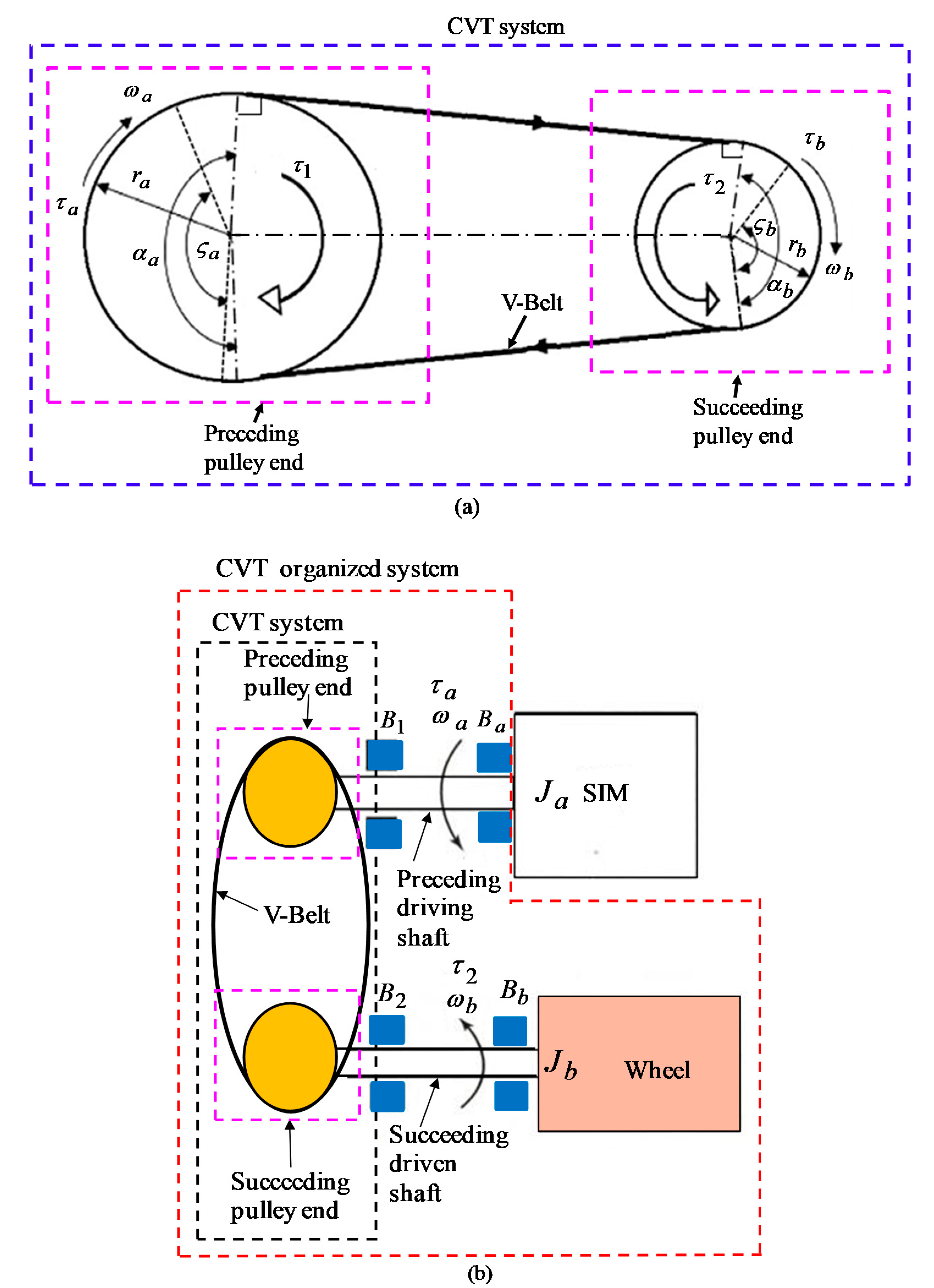
Figure 1. Conformation of the six-phase induction motor (SIM) and continuously variable transmission (CVT) organized system: (a) geometric components of the CVT system and (b) geometric components of the CVT organized system.
Mathematics 08 00754 g001
Figure 2. Conformation of the SIM expelling CVT organized system.
Mathematics 08 00754 g002
Figure 3. Block diagram of the MMRRSPNN control with MGWO by using two linear adjusted factors.
Mathematics 08 00754 g003
Figure 4. Constitution of the MRRSPNN.
Mathematics 08 00754 g004
Figure 5. Flowchart of the implemented program by DSP control system.
Mathematics 08 00754 g005
Figure 6. Tested results for the SIM expelling CVT organized system at the tested Event E1 case by using the controller CT1: (a) speed response, (b) speed discrepancy response.
Mathematics 08 00754 g006
Figure 7. Tested results for the SIM expelling CVT organized system at the tested Event E2 case by using the controller CT1: (a) speed response, (b) speed discrepancy response.
Mathematics 08 00754 g007
Figure 8. Tested results for the SIM expelling CVT organized system by using the controller CT1: (a) response of developed torque at the tested Event E1 case, (b) response of developed torque at the tested Event E2 case.
Mathematics 08 00754 g008
Figure 9. Tested results for the SIM expelling CVT organized system at the tested Event E1 case by using the controller CT2: (a) speed response, (b) speed discrepancy response.
Mathematics 08 00754 g009
Figure 10. Tested results for the SIM expelling CVT organized system at the tested Event E2 case by using the controller CT2: (a) speed response, and (b) speed discrepancy response.
Mathematics 08 00754 g010
Figure 11. Tested results for the SIM expelling CVT organized system by using the controller CT2: (a) response of developed torque τ a at the tested Event E1 case, (b) response of developed torque τ a at the tested Event E2 case.
Mathematics 08 00754 g011
Figure 12. Tested results for the SIM expelling CVT organized system obtained at the tested Event E1 case by using the controller CT3: (a) speed response, (b) speed discrepancy response.
Mathematics 08 00754 g012
Figure 13. Tested results for the SIM expelling CVT organized system at the tested Event E2 case by using the controller CT3: (a) speed response, (b) speed discrepancy response.
Mathematics 08 00754 g013
Figure 14. Tested results for the SIM expelling CVT organized system by using the controller CT3: (a) response of developed torque τ a at the tested Event E1 case, (b) response of developed torque τ a at the tested Event E2 case.
Mathematics 08 00754 g014
Figure 15. Tested results at the tested Event E1 case by using the controller CT3: (a) convergent response of learning rate ε 1 , (b) convergent response of learning rate ε 2 .
Mathematics 08 00754 g015
Figure 16. Tested results at the tested Event E2 case by using the controller CT3: (a) the convergent response of learning rate ε 1 , (b) the convergent response of learning rate ε 2 .
Mathematics 08 00754 g016
Figure 17. Tested results at the tested Event E3 case by using the controller CT1: (a) speed-adjusted response; (b) current response in phase a.
Mathematics 08 00754 g017
Figure 18. Tested results at the tested Event E3 case by using the controller CT2: (a) speed-adjusted response; (b) current response in phase a.
Mathematics 08 00754 g018
Figure 19. Tested results at the tested Event E3 case by using the controller CT3: (a) speed-adjusted response; (b) current response in phase a.
Mathematics 08 00754 g019
Table 1. Performance comparison of control systems.
Control System and Three Tested CasesController CT1
Performance Tested Event E1 CaseTested Event E2 CaseTested Event E3 Case
Maximum errors of e a 88 r/min215 r/min398 r/min
Root mean square errors of e a 45 r/min60 r/min51 r/min
Control System and Three Tested CasesController CT2
Performance Tested Event E1 CaseTested Event E2 CaseTested Event E3 Case
Maximum errors of e a 69 r/min88 r/min198 r/min
Root mean square errors of e a 30 r/min31 r/min27 r/min
Control System and Three Tested CasesController CT3
Performance Tested Event E1 CaseTested Event E2 CaseTested Event E3 Case
Maximum errors of e a 40 r/min43 r/min69 r/min
Root mean square errors of e a 20 r/min22 r/min17 r/min
Table 2. Characteristic performance comparisons of control systems.
Control SystemControl System CT1Control System CT2Control System CT3
Characteristic Performance
Vibration value in the control ruleSmall (10% of nominal value at tested Event E2 case)smaller (8% of nominal value at tested Event E2 case)Smallest (6% of nominal value at tested Event E2 case)
Dynamic responseSlow (rising time as 2.0 sec at tested Event E2 case)Fast (rising time as 1.8 sec at tested Event E2 case)Faster (rising time 1.6 sec at tested Event E2 case)
Regulation capability for load torque disturbancePoor (maximum error as 398 r/min at tested Event E3 case) Good (maximum error as 198 r/min at tested Event E3 case)Better (maximum error as 69 r/min at tested Event E3 case)
Convergent speed Slow (settle time as 2.5 sec at tested Event E2 case)Fast (settle time as 2.2 sec at tested Event E2 case)Faster (settle time as 2.0 sec at tested Event E2 case)
Speed tracking errorLarge (maximum error as 215 r/min at tested Event E2 case)Middle (maximum error as 88 r/min at tested Event E2 case)Small (maximum error as 43 r/min at tested Event E2 case)
Rejection ability for parameter disturbancePoor (maximum error as 215 r/min at tested Event E2 case)Good (maximum error as 88 r/min at tested Event E2 case)Better (maximum error as 43 r/min at tested Event E2 case)
Two learning ratesNoneVary (two optimal learning rates)Vary (two optimal learning rates)
Torque ripple (V-belt shaking action and torsional vibration variations)Large (12% of nominal value at tested Event E2 case)Smaller (10% of nominal value at tested Event E2 case)Smallest (6% of nominal value at tested Event E2 case)