Article

Preliminary Analysis of a Fully Ceramic Microencapsulated Fuel Thermal–Mechanical Performance

1
Shanxi Key Lab. of Advanced Nuclear Energy and Technology, School of Nuclear Science and Technology, Xi’an Jiaotong University, Xi’an 710049, China
2
Science and Technology on Reactor System Design Technology Laboratory, Nuclear Power Institute of China, Chengdu 610200, China
*
Authors to whom correspondence should be addressed.
Mathematics 2019, 7(5), 448; https://doi.org/10.3390/math7050448
Submission received: 20 March 2019 / Revised: 29 April 2019 / Accepted: 30 April 2019 / Published: 20 May 2019
(This article belongs to the Special Issue Mathematical Physics II)

Abstract

:
In this paper, a two-dimensional characteristic unit was used to simulate the thermal–mechanical performance of a fully ceramic microencapsulated (FCM) fuel pellet, and the criterion of FCM structure integrity was discussed. FCM structure integrity can be reflected though the integrity of the silicon carbide (SiC) matrix or SiC layers because of the excellent fission retention capability of SiC ceramics. The maximum temperature of the SiC matrix under normal conditions of the pressure water reactor (PWR) environment was about 1390 K, which was lower than the decomposition point of SiC. The maximum hoop stress of the SiC matrix, especially the inner part, was up to about 1200 MPa, and the hoop stress of the non-fuel region part was lower than the inner part, which can be attributed to the deformation of tristructural-isotopic (TRISO) particles. The hoop stress of the SiC layers at the end of life was only about 180 MPa, which is much lower than the strength of the chemical vapor deposition (CVD)-SiC. The failure probability of the SiC layer was lower than 9 × 10⁻⁵; thus, the integrity of SiC layers and the fission retention capability were maintained. The structure integrity of FCM fuel was broken because the SiC matrix cracked.

1. Introduction

Fully ceramic microencapsulated (FCM) fuel, which can improve the accident tolerance of light water reactors (LWRs), receives much attention because of its excellent oxidation resistance, fission retention capability, high thermal conductivity, and irradiation stability [1,2,3,4]. FCM was designed to improve the fission retention capacity during accident processes; fission retention capacity may be reflected by the integrity of the silicon carbide (SiC) matrix and layers. FCM is composed of historic tri-isotropic fuel embedded in a fully dense and impermeable SiC matrix. The tristructural-isotopic (TRISO) particle consists of the fuel kernel surrounded by four successive layers [5]: the low-density carbon buffer layer, whose function is to slow down and retain the generated fission product, and the inner and outer pyroltytic graphite layers, which surround the silicon carbide (SiC) micro pressure vessel. The function of the pyrolytic carbon is severalfold, including the protection of the kernel from aggressive process gases used during TRISO processing, to protect the SiC shell from energetic fission product recoil damage, and to provide thermal–mechanical stability and toughening for this multilayer system. Historically, TRISO and its fuel forms (graphite matrix compacts in the form of the cylindrical fuel of a prismatic high-temperature gas-cooled reactor or the spherical pebble of a pebble-bed modular high-temperature gas-cooled reactor) operate at a temperature in excess of 1000 °C. As the envisioned LWR application of the FCM fuel is at a less aggressive operating temperature for the TRISO (nominally 350–500 °C), it is anticipated that higher burn-ups and significantly improved safety benefits realized by the extraordinary fission product retention may be realized [6].
Lower fissile loading was an obvious shortcoming of FCM fuel compared with uranium dioxide (UO2) pellets. The feasibility of FCM fuel to satisfy the reasonable fuel cycle lengths in LWRs was demonstrated by Sen et al. [7]. The effect of the UO2 kernel size, enrichment, and type on the effective full power days (EFPD) was discussed. The results indicated that uranium nitride (UN) kernel FCM fuel can meet the fissile loading requirement of LWRs by optimizing the size of the kernel and coated layers. The sizes of the UN kernel and buffer layer were 800 μm and 100 μm, respectively, and the fraction of the FCM had to be higher than 44 vol.%. The thermal–mechanical performance of the TRISO with UO2 kernels was simulated by PARFUM, PASTA, and other models [8]. In the CO production model, internal pressure and gap heat transfer were considered. The Recoil and Booth models were used to calculate the fission gas release. The thermal and mechanical performance of the coated layer can be calculated in the above models. The performance of the UN kernel TRISO fuel in the LWR environment was reported, and the influence of temperature and kernel size on internal pressure and the survivability of TRISO fuel was studied [9]. The tangential stress of the inner pyrocarbon (IPyC) and SiC layers was calculated using COMSOL multi-physics software (COMSOL-5.2, MERCURY LEARNING AND INFORMATION LLC, Dulles, Virginia). However, the influence of the SiC matrix on TRISO particle performance was not discussed.
The thermal–mechanical performance of FCM pellets is difficult to simulate because of its complex structure and material properties. The temperature field and thermal conductivity of FCM pellets were studied previously [10,11,12], but thermal and mechanical coupled simulation results are rare. The temperature of the FCM pellet used in a pressure water reactor (PWR) environment was calculated by COMSOL software in the literature [10]. Both homogeneous and heterogeneous models were used in the report, and the calculated result of the homogeneous models was in good agreement with the result calculated by RELAP. The mechanical performance of FCM was not studied. Ougouag and co-workers [13] studied the influence of the SiC matrix on the performance of TRISO fuel by adding an SiC matrix on the outer surface of a single TRISO particle model. The results indicate that the thickness of the SiC matrix has an obvious influence on the stress distribution of the SiC and IPyC layers. The structure and coated layer size can affect the stress condition of the FCM. The SiC layer stress increased upon ignoring the outer pyrocarbon (OPyC) layer or increasing the SiC matrix thickness. The stress of the SiC layer with a matrix was much higher than the single particle. Schappel [14] simulated the thermal–mechanical performance of an FCM pellet and TRISO particle separately using ABAQUS software. TRISO particles were subtracted from the FCM pellet to simplify the model and decrease the computation amount. The performance of the coated layers was not detected, and the interaction between the TRISO particle and matrix was not reflected in the literature.
There is no criterion to evaluate the integrity of the FCM pellet, and the integrity of the FCM pellet was not studied in previous work as far as we know. In this paper, the integrity of the FCM pellet was defined according to fission retention capacity. The integrity of the FCM pellet under a PWR environment was discussed by investigating the mechanical performance and failure probability of the SiC matrix and SiC layers. A two-dimensional model was established, while the buffer layer and fuel kernel were subtracted from the FCM pellet. The internal pressure of TRISO particles embedded in different locations of FCM fuel was calculated using a TRISO simulation. The interaction between the TRISO particle and the SiC matrix was investigated, and the thermal–mechanical properties of the coated layers and SiC matrix were discussed. The fission production capacity of the FCM pellet was evaluated by investigating the failure probability of SiC layers and the hoop stress of the SiC matrix.

2. Governing Equation and Material Properties

2.1. Governing Equation

COMSOL multi-physics software offered the heat transfer model for the solid materials to calculate the temperature distribution in FCM and TRISO fuel. The temperature field of FCM pellet and TRISO fuel are determined by the heat conduction equation:
ρ C p T t + q E f F ˙ = 0
where T, ρ and Cp are the temperature, density (kg/m3) and heat capacity (J/(kg∙K)) of the solid material, respectively. Ef and F ˙ are the energy released in a single fission event and volumetric fission rate, respectively. The heat flux can be written as follows:
q = k T .
The stress in all coated layers and the SiC matrix was caused by the accumulation of internal pressure and the deformation of other materials. The internal pressure of TRISO fuel was caused by fission gas release. The TRISO particle located in a different part of the FCM pellet possessed a different internal pressure caused by the temperature gradient of the FCM pellet [9]. The deformation of the coated layers and SiC matrix was caused by the internal and outer pressure, thermal expansion, irradiation and creep strain. The strain tensor of FCM was written as follows:
ε = ε e + ε T + ε i + ε c
where ε is the strain, εe, εT, εi and εc represent the elastic strain, thermal expansion strain, irradiation strain and creep strain.

2.2. Material Properties

The properties of dense pyrolytic carbon, SiC layer, and SiC matrix were used in this simulation. The properties of dense pyrolytic carbon in PASTA code used in a high temperature gas cooled reactor have been employed to analyze the performance of the FCM pellet in an LWR environment by Idaho National Laboratory (INL), and the appropriateness of the properties of dense pyrolytic carbon have been proved in previous works [15,16]. The appropriateness of the properties of SiC ceramics described in the following part used in an LWR environment, has been reported [17,18].

2.2.1. Dense Pyrolytic Carbon (PyC) Layers

The properties of the SiC layer, SiC matrix and PyC materials are taken into account in this paper. The elastic modulus of the PyC layer is anisotropic and can be calculated by the following Equation [19]:
E P y C = 25.5 ( 0.384 + 0.000324 ρ P y C ) ( 0.481 + 0.519 B A F ) ( 1 + 0.23 Φ ) ( 0 . 9560275 + 0.00015 T )
where Φ is the neutron flux (×1025 n/m2), T is the temperature (K), and BAF is the anisotropic parameters of PyC.
The radial and tangential irradiation strain of the PyC layers are expressed by the following equations [17]:
ε ˙ r = 0.077 exp ( Φ ) + 0.031
ε ˙ θ = 0.036 exp ( 2.1 Φ ) 0.01 .
The irradiation deformation of PyC (as shown in Equations (5) and (6)) was saturated when the neutron flux reached 8.14 × 1025 n/m2 [16].
Equation (7) is given to calculate the creep strain of the PyC layers along the radial and other directions [17].
ε ˙ c r , r = K p y c [ σ r ν c ( σ θ + σ ϕ ) ] Φ ˙
where Φ ˙ is the fast neutron flux rate (1025n·m−2·s−1), vc is the Poisson ratio (vc = 0.23), and Kpyc is the temperature-dependent creep coefficient.

2.2.2. SiC Layer and SiC Matrix

The elastic modulus and thermal expansion coefficient of the SiC layer are represented as in the following equations [17]:
E S i C = 460 0.04 T exp ( 962 T )
α s i c ( × 10 6 ) = { 1.8267 + 0.0178 T 1.5544 × 10 5 T 2 + 4.5246 × 10 9 T 3 T < 1273 K 5.0 T > 1273 K
where E and α are the elastic modulus and thermal expansion coefficient, respectively.
The swelling model of the SiC matrix is the function of temperature and neutron flex, which can be written as follows [19]:
S = k s γ 1 / 3 exp ( γ γ s c )
where S is the swelling rate (s−1), Ks is the coefficient of the swelling rate (dpa−2/3), γ is the neutron flux (dpa), and γsc is the characteristic dose for swelling saturation by the negative feedback mechanism (dpa). The swelling of the SiC can be obtained from the time integration of Equation (10):
S = S s [ 1 exp ( γ γ s c ) ] 2 / 3
where Ss and γsc are the function of the temperature and can be expressed as follows:
S s ( T ) = 0.05837 1.0089 × 10 4 T + 6.9368 × 10 8 T 2 1.8152 × 10 11 T 3
γ s c ( d p a ) = 0.4603 + 2.6674 × 10 3 T 4.3176 × 10 6 T 2 + 2.3803 × 10 9 T 3 .
Figure 1 shows the swelling of SiC materials as a function of temperature and dose calculated from Equation (11).
The thermal expansion coefficient of the SiC matrix is expressed as follows [20]:
α ( 10 6 / K ) = 0.7738 + 7.080 × 10 3 T 4.951 × 10 6 T 2 + 1.372 × 10 9 T 3 .
The thermal conductivity of the SiC layer is different from that of the SiC matrix due to the differences in their fabrication and chemical components. Si and C exhibit similar electronegative properties; thus, SiC is mainly combined by C and Si with a covalent bond, according to the Principle of Electro negativity. Unirradiated SiC thermal resistance increases with temperature and defects due to an increase in phonon-phonon scattering. Because of irradiation can increase the quantity of defects, the thermal resistance of SiC increased. The thermal resistance of SiC can be simplified as Equation (15) by neglecting the contribution to the electron to the thermal conductivity at a high temperature [21]:
1 k = R 0 + R i r r
where R0 and Rirr are the thermal resistance (K/W) of the prior- and post-irradiated SiC, respectively.
The thermal resistance of the unirradiated SiC lay and matrix is expressed as below:
R 0 = 1 3.7 × 10 8 T 3 + 1.54 × 10 4 T 2 0.214 T + 153.1 .
The thermal resistance induced by the irradiation can be written:
R i r r = 1 6.08 S
where S is the irradiation-induced volume swelling shown in Equation (11).
Failure probability of the SiC layer can be reflected by the stress distribution. The failure probability of brittleness material can be calculated by the following Equation [19]:
P = 1 exp [ V ( σ p / σ 0 ) m d V ]
where V is the characteristic volume, m is the Weibull modulus of the SiC layer, and σ0 is the characteristic strength, while σp is the true stress. The characteristic strength and the Weibull modulus of the SiC layer were 350 MPa and 5, respectively [15].

3. Geometry and Boundary Conditions

The performance of a TRISO particle with a UN kernel was simulated in our previous work [22], and the calculated internal pressure at a different temperature of TRISO was used as input parameters for the FCM pellet simulation. A 1/8 sphere unit was used to simulate the performance of the TRISO particle by defining the boundary condition. The heat source of the TRISO particle was conversed from the liner power of the FCM pellet. The surface temperature was set according to the calculated result of the FCM pellet. The symmetry boundary condition was set on the 3 side surfaces. The structure and boundary condition schematic diagram of the TRISO particle unit is shown in Figure 2. The typical size of the TRISO particle had been studied in [22], and the size of the kernel and coated layers have great influence on the performance of TRISO particles. The structural size of the TRISO particle was similar with that of our previous work [23] and was set as follows: the diameter of the UN kernel was 800 μm, while the thickness of buffer, IPyC, SiC, and OPyC layers were 100 μm, 30 μm, 40 μm, and 30 μm, respectively.
The FCM pellet with 39.8 vol.% TRISO particle loading was simulated in this work. The diameter and height of the FCM pellet was 7 mm and 7 mm, respectively. A three-dimensional model is shown in Figure 3. In order to decrease the calculated quantity of the FCM pellet, a 2-dimensional model was used in this simulation. The 2-dimensional unit was obtained from the 3-dimensional one; the cutting pattern is shown in Figure 3.
Figure 4 shows the 2-dimensional model; the structure and boundary condition was also revealed. The kernel and buffer layers were separated from the IPyC layer during the operation process and have little influence on the performance of the other coated layers and the SiC matrix; this phenomenon has been proven by previous works [19,22]. The kernel and buffer layers were subtracted from the TRISO particle, and the other coated layers, including the IPyC, SiC, and OPyC layers were reserved to reflect the SiC layer’s performance and to simulate the interaction between the coated layers and the SiC matrix. The side surface temperature of the FCM pellet was set as about 800 K, which was set as a solid heat transfer boundary. Heat flux was set on the IPyC surface per particle and the value was about 3.53 × 10⁵ W/m2, which corresponds to an average linear power of 315 W/cm for the FCM pellet. The internal pressure has an obvious effect on the performance of the coated layers, and the internal pressure of the TRISO particle was calculated from the TRISO particle model at a different surface temperature. The bottom part of the FCM pellet was set as a spring foundation to assure simulation convergence. The pressure on the side surface was set as a constant value (P = 2 MPa), which corresponds to the helium pressure of the fuel rod.
A schematic of the calculation flow in the COMSOL software was is shown in Figure 5, and each part of the computable flow graph was described as follows. The two-dimensional model was used to simulate the performance of the FCM pellet. Solid mechanics and heat transfer modules were selected to calculate the temperature and mechanical field of the FCM under a normal condition. The three-dimensional model of the FCM pellet was established, and the two-dimensional model was obtained from the three-dimensional ones, as shown in Figure 3. The geometric model was established by set the size of pellet and coated layers. The material model and boundary condition, as mentioned above, was input, and the grid was subdivided using the native function of COMSOL, according to the physical field. The temperature and stress field of the FCM pellet was output.

4. Results and Discussion

4.1. Temperature Distribution of FCM Pellet

The calculated temperature distribution of an FCM pellet in an LWR environment is shown in Figure 6. The highest temperature of the SiC matrix was located in the center of the FCM pellet, and the maximum temperature at the end of life was about 1390 K, which was similar with the results in the literature [14]. The maximum matrix temperature was much lower than the decomposition or molten point of SiC. The maximum temperature increased rapidly at the beginning and was followed by a slower linear increase. The swelling of the SiC matrix is the function of temperature and neutron flex, which can cause thermal conductivity degradation of SiC matrix, as discussed in the above section (shown in Equation (17)). The thermal conductivity of the SiC matrix reached an essentially steady state condition after 100 d when the SiC swelling reached saturation at about 1 dpa. The maximum temperature of the SiC matrix was much lower than that of the UO2 pellet in the same operational environment, which was attributed to the high thermal conductivity of the SiC matrix.

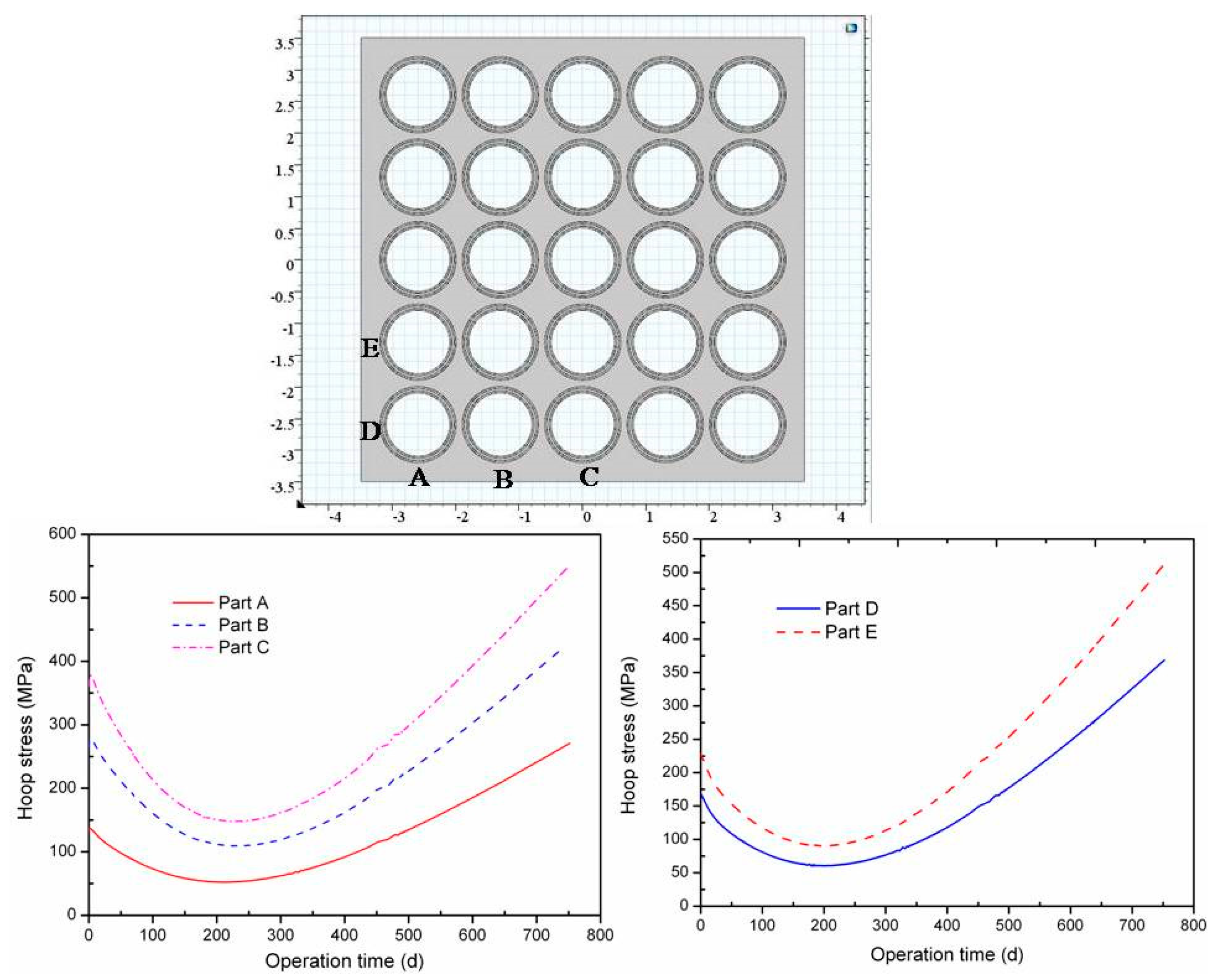
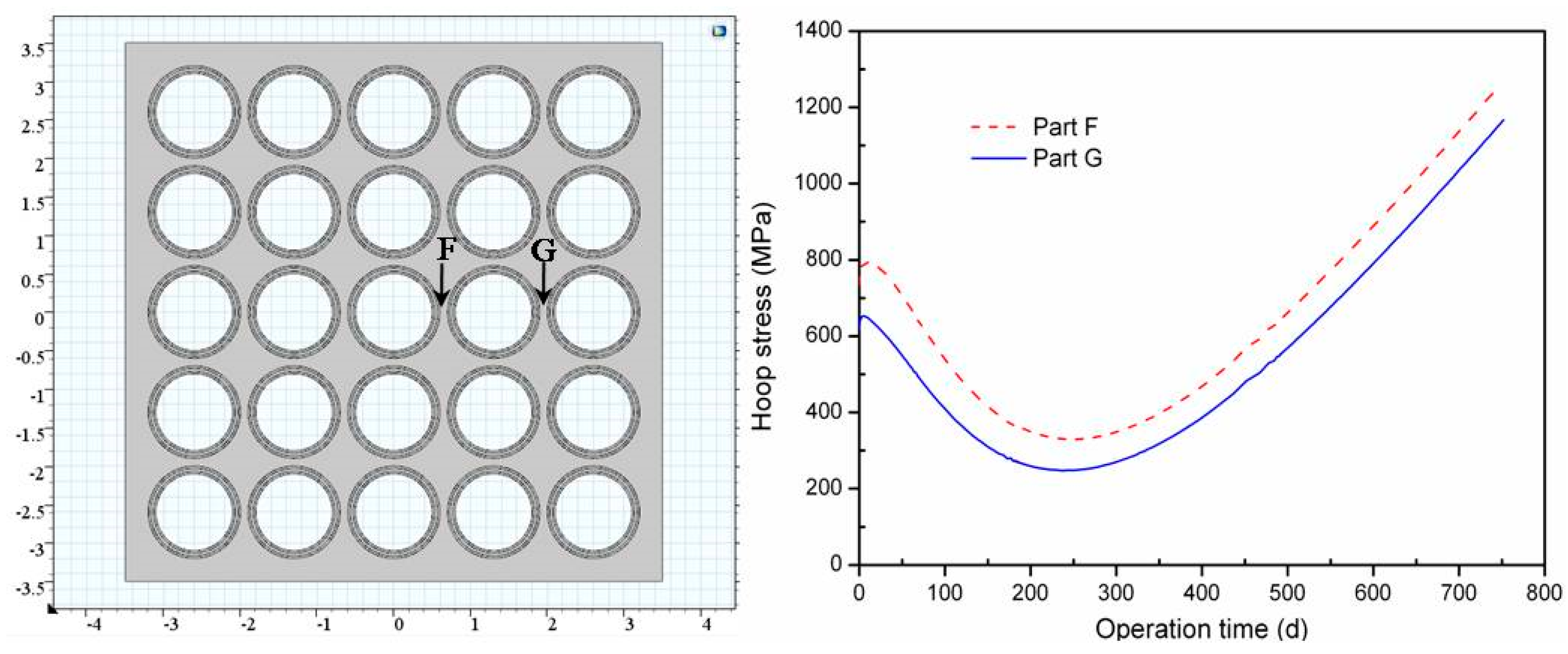
4.2. Mechanical Performance of SiC Matrix

The internal pressure of TRISO particles located at different part of the FCM pellet was calculated using a 1/8 sphere unit model. Internal pressure of the TRISO particle with a different surface temperature is shown in Figure 7. The internal pressure of the TRISO particle increased with the surface temperature. No interaction occurred between the UN kernel and Buffer layers, and the internal pressure was caused by the fission gas. The calculated result was similar with the reported ones, which used UN as a TRISO kernel [23], but the internal pressure was much lower than that in the literature [14]. This result may be attributed to the different kernel, and the interaction between the UO2 and Buffer layer may increase the internal pressure dramatically. The internal pressure increased with burn up linearly because of the increase in fission gas production. The maximum internal pressure was about 3 MPa at 1400 EFPD when the surface temperature was up to 1200 K, which was in good agreement with the literature [22]. Internal pressure has an obvious influence on the stress distribution of the TRISO particle and the FCM pellet.
Variation of hoop stress on marginal parts of the FCM pallet (non-fuel part) is shown in Figure 8. The bottom part (Parts A, B, and C) shows relatively lower stress than the side part (Parts D and E), which may be caused by the different temperature gradient. Because of the higher temperature of the inner matrix (shown in Figure 6), a higher thermal deformation was induced; thus, the hoop stress of the inner part (Parts B and C) was much higher than that of the outer part (Part A). The non-fuel part hoop stress was up to about 500 MPa at the end of life, which was confirmed by the literature [14]. Cracks may be produced because of the high hoop stress of the SiC matrix during the running operation, but the cracks may have disappeared or been deflected when the cracks extended to the interface between the matrix and the TRISO particles [6]; the formation and extension of cracks will be investigated in our future work. The hoop stress decreased at the beginning and then increased. The variation of hoop stress may be attributed to the irradiation deformation of the PyC layers; the shrinkage of PyC at the beginning may release the stress of SiC matrix, and then the swelling of PyC may cause an increase in hoop stress.
Figure 9 shows the hoop stress of the inner SiC matrix located between the two TRISO particles. The maximum hoop stress of the inner SiC matrix was up to 1200 MPa at the end of life, and this result was in good agreement with the literature [14] (the maximum value in the literature was about 1160 MPa). The inner SiC matrix between two TRISO particles suffered large hoop stress; the stress decreased at the beginning and then increased. This phenomenon was caused by the interaction between the TRISO particle and the SiC matrix. The hoop stress of the SiC matrix, including the non-fuel region and the inner part, was higher than the SiC’s intrinsic strength, and the SiC matrix may be broken during the operation process.

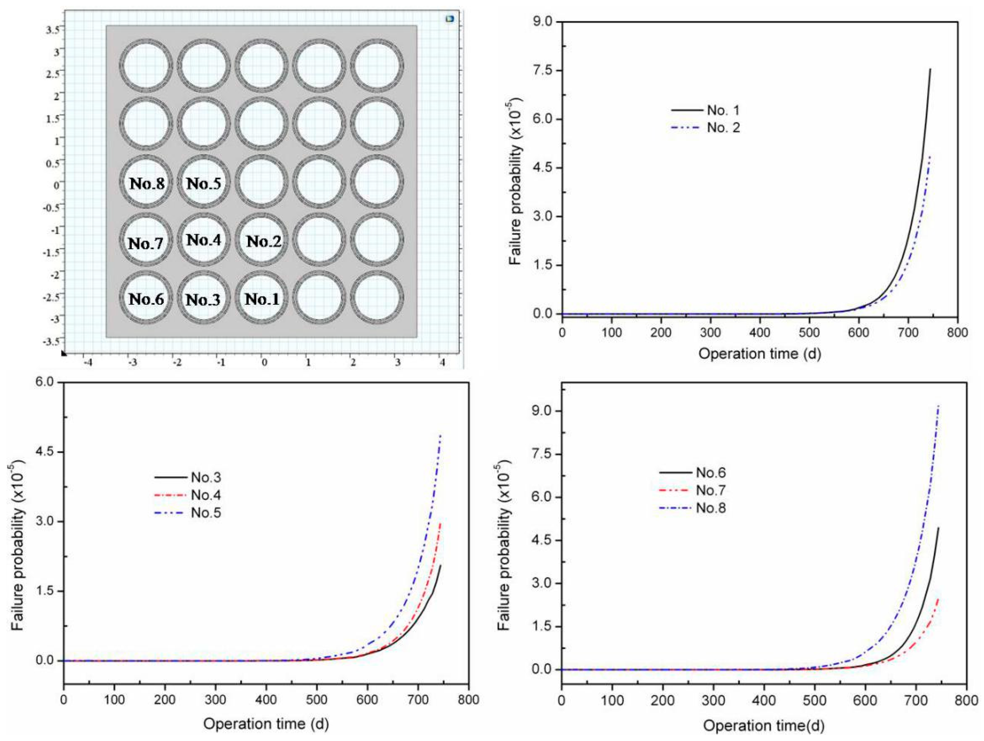
4.3. Mechanical Performance of SiC Layer

The fission product capabilities of FCM can be reflected by the structural integrity of the SiC matrix and the the SiC layers in the TRISO particles. The fission products can be effectively prevented by the SiC layers, which have been proven by an advanced gas cooled reactor [8]. The thermal-mechanical performance and failure probability of the SiC layers were important parameters to evaluate the integrity and fission product capabilities of FCM. There was no consideration of SiC layer performance on FCM pellets in previous reports as far as we know. The performance of the SiC layer located in different parts of the FCM pellet was calculated in this work.
The hoop stress of the SiC layers in TRISO particles, which embed in different parts of the FCM pellet, is shown in Figure 10, and the detected TRISO particles were labeled. SiC layers located in different parts of the FCM suffered different hoop stress. TRISO particles located in the inner part of the FCM (such as No. 1, No. 2, No. 5 and No. 8) suffered high hoop stress, which can be attributed to the high temperature gradient and thermal deformation. The maximum hoop stress of the SiC layers was about 180 MPa, which was much lower than the SiC strength (350 MPa) [15]. The maximum stress of the SiC layer was similar to the literature [19]. The hoop stress of all the SiC layers decreased at the beginning, and this result may be attributed to the irradiation deformation of the IPyC and OPyC layers, which was similar to the calculated result of the TRISO particles [22]. The irradiation deformation of the IPyC and OPyC layers can protect the SiC layers at the beginning time [19]. Then, irradiation deformation of the IPyC and OPyC layers was saturated, and the protective effect disappeared, thus the hoop stress of the SiC layer increased. The irradiation deformation of the SiC matrix may pull or push the TRISO particles located in different parts of FCM pellet, which may increase the hoop stress of the SiC layers.
The failure probability of the SiC layers located in different parts of the FCM pellet is shown in Figure 11. They are higher than the single TRISO particle with probabilities lower than 5.0 × 10⁻⁵ [22], which was confirmed by the stress distribution of the SiC layer. Similar to the single TRISO particle model, the pressure contribution to SiC failure was very limited because of the low gas release and internal pressure of the TRISO particles with the UN kernel under a PWR environment (shown in Figure 7). The maximum failure probability of the TRISO was No. 8 (showed in Figure 11), which was the inner one located on the side edge of FCM pellet. A large temperature gradient and matrix swelling deformation at a relatively low temperature (shown in Figure 1) may induce large hoop stress on the SiC layer, and the failure probability increased. As a whole, the SiC layers located in different parts of the FCM pellet suffered low stress and the integrity of the SiC layers was maintained.

5. Conclusions

A two-dimensional model of an FCM pellet with a homogenous distribution of TRISO particles was generated to simulate the thermal-mechanical performance of an FCM pellet. The UN kernel and buffer layers were subtracted because the kernel and buffer layer were separated from other coated layers and have little influence on the thermal-mechanical performance of the SiC layer and matrix, which has been proven by a high temperature gas cooled reactor. The interaction between the matrix and TRISO particle was considered, and the performance of SiC layer and matrix were calculated. The maximum matrix temperature increased rapidly at the beginning and was followed by a slower linear increase, which corresponded to the degradation of SiC thermal conductivity. The SiC matrix, including the non-fuel region and inner parts, suffered a large hoop, which can break the SiC matrix. The maximum hoop stress of the SiC layers located in different parts was about 180 MPa, which was much lower than the intrinsic strength of the SiC ceramics. The failure probability of the SiC layers was lower than 9 × 10⁻⁵, which indicated that the structural integrity of the SiC layers was maintained. The integrity of the SiC layers is beneficial to the capacity of fission product retention.

Author Contributions

Conceptualization, P.C. and S.Q.; methodology, S.L.; software, S.L.; validation, Y.Z., Y.X. and S.G.; formal analysis, H.L.; investigation, X.Q.; resources, X.Q.; data curation, P.C.; writing—original draft preparation, S.L.; writing—review and editing, X.Q.; visualization, X.Q.; supervision, S.Q.; project administration, P.C.; funding acquisition, P.C.

Funding

This research received no external funding.

Conflicts of Interest

The authors declare no conflict of interest.

References

  1. Chun, J.H.; Lim, S.W.; Chung, B.D. Safety evaluation of accident-tolerant FCM fueled core with SiC-coated zircalloy cladding for design-basis-accidents and beyond DBAs. Nucl. Eng. Des. 2015, 289, 287–295. [Google Scholar] [CrossRef] [Green Version]
  2. Snead, L.L.; Terrani, K.A.; Venneri, F. Fully ceramic microencapsulated fuels: A transformational technology for present and next generation reactors-properties and fabrication of FCM fuel. Trans. Am. Nucl. Soc. 2011, 104, 668–670. [Google Scholar]
  3. Snead, L.L.; Terrani, K.A.; Katoh, Y. Stability of SiC-matrix microencapsulated fuel constituents at relevant LWR conditions. J. Nucl. Mater. 2014, 448, 389–398. [Google Scholar] [CrossRef]
  4. Lu, C.; Hiscox, B.D.; Terrani, K.A. Fully ceramic microencapsulated fuel in prismatic high temperature gas-cooled reactors: Analysis of reactor performance and safety Characteristics. Ann. Nucl. Energy 2018, 117, 277–287. [Google Scholar] [CrossRef]
  5. Terrani, K.A.; Zinkle, S.J.; Snead, L.L. Snead, Microencapsulated fuel technology for commercial light water and advanced reactor application. J. Nucl. Mater. 2012, 427, 209–224. [Google Scholar] [CrossRef]
  6. Terrani, K.A.; Kiggans, J.O.; Katoh, Y. Fabrication and characterization of fully ceramic microencapsulated fuels. J. Nucl. Mater. 2012, 426, 268–276. [Google Scholar] [CrossRef]
  7. Sen, R.S.; Pope, M.A.; Ougouag, A.M. Assessment of possible cycle lengths for fully encapsulated microstructure fueled light water reactor concepts. Nucl. Eng. Des. 2013, 255, 310–320. [Google Scholar] [CrossRef]
  8. Powers, J.J.; Wirth, B.D. A review of TRISO fuel performance models. J. Nucl. Mater. 2010, 405, 74–82. [Google Scholar] [CrossRef]
  9. Besmann, T.M.; Ferber, M.K.; Lin, H.T. Fission product release and survivability of UN-kernel LWR TRISO fuel. J. Nucl. Mater. 2014, 448, 412–419. [Google Scholar] [CrossRef]
  10. Kamalpour, S.; Salehi, A.A.; Khala, H. The potential impact of Fully Ceramic Microencapsulated (FCM) fuel on thermal hydraulic performance of SMART reactor. Nucl. Eng. Des. 2018, 339, 39–52. [Google Scholar] [CrossRef]
  11. Lee, Y.; Cho, N.Z. Steady and transient-state analyses of fully ceramic microencapsulated fuel loaded reactor core via two-temperature homogenized thermal conductivity model. Ann. Nucl. Energy 2015, 76, 283–296. [Google Scholar] [CrossRef]
  12. Lee, H.G.; Kim, D.; Lee, S.J. Thermal conductivity analysis of SiC ceramics and fully ceramic microencapsulated fuel composites. Nucl. Eng. Des. 2017, 311, 9–15. [Google Scholar] [CrossRef]
  13. Ougouag, A.M.; Kloosterman, J.L. Investigation of bounds on particle packing in pebble-bed high temperature reactors. Nucl. Eng. Des. 2006, 236, 669–676. [Google Scholar] [CrossRef]
  14. Schappel, D.; Terrani, K. Thermo Mechanical Analysis of Fully Ceramic Microencapsulated Fuel during in-Pile Operation; American Nuclear Society-ANS: La Grange Park, IL, USA, 2016. [Google Scholar]
  15. Boer, B.; Sen, S.R.; Pope, A.M. Material Performance of Fully-Ceramic Micro-Encapsulated Fuel under Selected LWR Design Basis Scenarios: Final Report; INL/EXT-11-23313; Idaho National Laboratory: Idaho Falls, ID, USA, 2011.
  16. Boer, B.; Ougouag, A.M. Stress analysis of coated particle fuel in graphite of High-Temperature Reactors. Nucl. Technol. 2008, 162, 276–292. [Google Scholar] [CrossRef]
  17. Miller, G.K.; Petti, D.A.; Maki, J.T. PARFUME Theory and Model Basis Report; Idaho National Laboratory, Next Generation Nuclear Plant Project; Idaho National Laboratory: Idaho Falls, ID, USA, 2009.
  18. Demancge, P.; Marian, J. TRISO fuel element thermal-mechanical performance modeling for the hybrid LIFE engine with Pu fuel blanket. J. Nucl. Mater. 2010, 405, 144–155. [Google Scholar] [CrossRef]
  19. Katoh, Y.; Koyanagi, T.; Singh, G.; Terrani, K.A.; Petrie, C.M.; Snead, L.L.; Deck, C. Irradiation-High Heat Flux Synergism in Silicon Carbide-Based Fuel Claddings for Light Water Reactors; American Nuclear Society-ANS: La Grange Park, IL, USA, 2016. [Google Scholar]
  20. Katoh, Y.; Ozawa, K.; Shih, C. Continuous SiC fiber, CVI SiC matrix composites for nuclear applications: Properties and irradiation effects. J. Nucl. Mater. 2014, 448, 448–476. [Google Scholar] [CrossRef]
  21. Stone, J.G.; Schleicher, R.; Deck, C.P. Stress analysis and probalibistic assessment of multi-layer SiC-based accident tolerant nuclear fuel cladding. J. Nucl. Mater. 2015, 466, 682–697. [Google Scholar] [CrossRef]
  22. Collin, B.P. Modeling and analysis of UN TRISO fuel for LWR application using the PARFUME code. J. Nucl. Mater. 2014, 451, 65–77. [Google Scholar] [CrossRef]
  23. Li, W.; Wu, X.; Liu, S. Performance analysis of TRISO coated fuel particle with UN kernel. Atom. Energy Sci. Technol. 2018, 52, 283–289. (In Chinese) [Google Scholar]
Figure 1. Variation of the swelling silicon carbide (SiC) material as functions of temperature and neutron flux.
Mathematics 07 00448 g001
Figure 2. Schematic diagram of a tristructural-isotopic (TRISO) particle characteristic unit. IPyC, inner pyrocarbon; OPyC, outer pyrocarbon.
Mathematics 07 00448 g002
Figure 3. A three-dimensional model of a fully ceramic microencapsulated (FCM) pellet with 39.8 vol.% TRISO particle loading.
Mathematics 07 00448 g003
Figure 4. Two-dimensional model of the FCM pellet; the structure and boundery condition were also revealed.
Mathematics 07 00448 g004
Figure 5. Computable flow graph of simulation process.
Mathematics 07 00448 g005
Figure 6. Matrix temperature profile at end of life (EOL) of FCM pellet and variation of the maximum matrix temperature with operation time.
Mathematics 07 00448 g006
Figure 7. Fission gas pressure inside the TRISO particle throughout its life time.
Mathematics 07 00448 g007
Figure 8. Variation of the hoop stress of the SiC matrix located in the marginal parts of the FCM pallet.
Mathematics 07 00448 g008
Figure 9. Variation of hoop stress of the inner SiC matrix located between two TRISO particles.
Mathematics 07 00448 g009
Figure 10. Variation of hoop stress on the SiC layer located in different parts in the FCM pellet.
Mathematics 07 00448 g010
Figure 11. Failure probability of the SiC layers located in different parts of the FCM pellet.
Mathematics 07 00448 g011

