Article

Numerical Performance Evaluation of Solar Photovoltaic Water Pumping System under Partial Shading Condition using Modern Optimization

1
National School of Engineering of Tunis, University of Tunis El Manar, BP 37, Tunis 1002, Tunisia
2
College of Engineering at Wadi Addawaser, Prince Sattam Bin Wadi Addawaser Abdulaziz University, Addawaser 11991, Saudi Arabia
3
Electrical Engineering Department, Faculty of Engineering, Minia University, Al Minya 61519, Egypt
4
Systems Engineering Department, King Fahd University of Petroleum & Minerals, Dhahran 31261, Saudi Arabia
5
Department of Physics, Faculty of Sciences, University of Tunis El Manar, BP 37, Tunis 1002, Tunisia
*
Authors to whom correspondence should be addressed.
Mathematics 2019, 7(11), 1123; https://doi.org/10.3390/math7111123
Submission received: 12 October 2019 / Revised: 12 November 2019 / Accepted: 13 November 2019 / Published: 16 November 2019

Abstract

:
Renewable energy is an attractive solution for water pumping systems particularly in isolated regions where the utility grid is unavailable. An attempt is made to improve the performance of solar photovoltaic water pumping system (SPVWPS) under partial shading condition. Under this condition, the power versus voltage curve has more than one maximum power point (MPP), which makes the tracking of global MPP not an easy task. Two MPP tracking (MPPT) strategies are proposed and compared for tracking MPP of SPVWPS under shading condition. The first method is based on the classical perturb and observe (P&O) and the other method is based on a Salp Swarm Algorithm (SSA). Based on extensive MATLAB simulation, it is found that the SSA method can provide higher photovoltaic (PV) generated power than the P&O method under shading condition. Consequently, the pump flowrate is increased. But, under normal distribution of solar radiation, both MPPT techniques can extract the maximum power but SSA is considered a time-consuming approach. Moreover, SSA is compared with particle swarm optimization (PSO) and genetic algorithm (GA). The obtained results ensure the superiority of SSA compared with PSO and GA. SSA has high successful rate of reaching true global MPP.

1. Introduction

With regularly lessening natural resources and expanding requests for power, the need to search for alternatives sources of renewable energy is not simply intense. Earnest renewable energy sources that are environmentally safe, have a cheap running cost, and low maintenance [1,2,3,4] are required. Stand-alone PV systems (PVSs) depicts the most encouraging application for water pumping, especially those situated in remote regions, where the expense of transporting fuel and power [5,6]. The standalone PVSs have been used in numerous developing countries e.g., Egypt, Sudan, Algeria, India etc., particularly in isolated rural zones, where there is no connection with utility [7,8]. Numerous African countries have an excellent level of solar irradiance intensity. In Egypt, the global solar irradiation per annum is over 2000 kWh/m2 [9,10,11]. This makes the standalone PVS an encouraging candidate. One of the most prevalent applications for PVS is the solar photovoltaic water pumping system (SPVWPS), especially in isolated areas. The harvested energy by SPVWPS feeds into the pumping system for various applications, for example, drinking water supplies and irrigation. Unfortunately, PVS has two main problems: the lower efficiency, and the harvested output power varies continuously with weather conditions. Additionally, the PVS characteristics are nonlinear. Their output power is subject to considerable variation of weather conditions, i.e., solar irradiance and temperature. To increase PVS efficiency, MPPT methods are necessary to harvest the maximum power from the PVS [12,13,14,15]. Such tracking methods are based on moving the operating PV voltage to provide the available maximum power. An effective and economic SPVWPS, needs to be designed properly, compared to the other pumping systems that are connected to the grid or diesel generator, particularly in rural areas [16]. However, the low efficiency of energy conversion, the non-linear (I-V) characteristic, the optimum point at which maximum power can be derived, remain the main challenges of this technology [17,18,19]. In [20], the authors examined the opportunities and challenges facing the SPVWPS. In fact, they briefly deal with the economic, social, and technical implications of the target system. As they have demonstrated that SPVWPS may have the lowest life-cycle cost compared to classical water pumping systems, which have been powered by the grid or the diesel generator. Following in the same vein, the SPVWPS design procedure in terms of sizing, assembly and monitoring are analyzed [21]. A theoretical and experimental study on the performance of an SPVWPS under climatic conditions of Tunisia are carried out [22]. The modelling of this photovoltaic structure consisting of a photovoltaic generator, buck converter, inverter, asynchronous machine, submersible pump, and storage tank, is performed through using MATLAB/Simulink. The global model consists of the entire structure previously developed with the introduction of an MPPT control technology. Under constant solar irradiation, the authors pointed out that generated PV power and flow rate characterizing the pump are strongly dependent on radiation. In addition, changes in climatic factors have adversely affected the performance of the pumping system. The experimental study revealed that the best performance of SPVWPS was clearly visible in the middle of day and the experimental results conform well to the theoretical results. In addition, [23] has reviewed the recent developments on SPVWPS, which are employed in a specific area. Thus, the authors have examined most of the technologies applied to SPVWPS in Algeria, with an emphasis on systems’ performance, modelling and sizing. However, these synthesis papers do not deal with the critical analysis of the recent developments, although the focus has been placed on a systems’ feasibility and design procedure. On the other hand, some archived reviews have discussed issues of SPVWPS technologies, as mentioned [24,25]. Authors in [24] have reviewed studies about SPVWPS, with an emphasis on their performance, economic and environmental impacts. They are also interseted in control strategy and sizing. In the same vein, [25] has referred to research papers on SPVWPS power electronics characteristics. This work examines studies done on maximum power point tracking technology (MPPT). However, [24] was interested in a limited number of works, which do not focus strictly on SPVWPS. As a result, nothing has been discussed about critical challenges, control, modelling and sizing of this system. In [25], the study focused particularly on the control strategy of SPVWPS, based on MPPT technology without taking account others control strategies. Moreover, the system performance, modelling and sizing were not taken into account in this review. A detailed study on SPVWPS has been carried out by [26]. The authors were limited to the latest updates of SPVWPS in terms of technology, performance, sizing, economic and environmental considerations. In addition, factors affecting the PV efficiency degradation and performance of a system, are examined. In general, a three-phase engine powered by a PV generator is relatively well known in the literature, while the single-phase induction motor dedicated to low-power applications (which is widely used for domestic purposes) has never been studied. Author in [27] analysed the performance of a single-phase induction motor (SPIM) connected to PV generator via an inverter. The mathematical model of the suggested structure has been addressed. Subsequently, he adopted the rotor flux orientation vector control (IRFOC) to drive the single-phase induction motor, connect to a centrifugal pump. In the same study, the MPPT power detection algorithm, which contributes to the good operation of the pump, was used to meet the required flow rate and head. The approach proposed by [27], therefore has the advantage of not using the DC-DC converter and has a low cost. The obtained results of the tracking process lead to higher efficiency of the overall functioning of the pumping system. The profitability and feasibility of the proposed method have been confirmed by simulation results. In [28], the author suggested a solar water pumping system (SPV) incorporated with a single-phase distribution system through using an induction motor (IMD), which is equipped with an intelligent power sharing control. In addition, to the power exchange between the SPV and IMD, the author has introduced a Boost converter, serving as a power factor correction unit and ensures interfacing with the grid. According to [28], to guarantee a reliable use of this panel (SPV), it appears necessary to extract the maximum power from it. This is achieved by implementing a maximum power point tracking (MPPT) control based on incremental conductance, while to control the induction motor, which is coupled to a voltage source inverter, the author used a simple scalar V/F control. The proposed topology is elaborated and tested in the laboratory according to different modes: stand-alone, grid connected, under different operating conditions.
One big issue that influences the performance of PV system is the partial shading condition (PSC). Under this condition, the PV power versus voltage curve includes many points of maximum power so any conventional MPPT unable to identify global. Several global tracking techniques based on modern optimization are proposed in order to extract the global MPP under shading condition. These techniques include Flower Pollination Algorithm [29], Teaching-Learning-Based Optimization [30], Cuckoo Search [31], Moth-Flame Optimization [32], Mine Blast Optimization [33], Particle Swarm Optimization [34,35], Differential Evolution [36], Jaya Algorithm [37], Grey Wolf Optimizer [38,39], Sine Cosine Algorithm [40] and shuffled frog leap algorithm [41]. A modified PSO based MPPT algorithm for a PV system operating under PSC, has been proposed by [35]. This technique can accurately track the global MPP under different shading patterns. However, it does allow to bypass their dependence on specific system parameters (such as the number of cells connected in series). In addition, the tracking results obtained from any global MPP search operation could vary due to the dependence of this technique on the number of iterations required to reach the global MPP. Based on the Grey Wolf Optimization Technique (GWO), authors in [39] proposed a new maximum power detection algorithm dedicated to PV generation systems which is: GWO-MPPT. The author used GWO because this technique was able to overcome most of the constraints related to the following techniques: Improved PSO (IPSO) and (P&O), such as low tracking efficiency and steady state oscillations. Based on the Firefly Optimization Algorithm (FOA), the duty cycle of the converter indicates the position on the firefly; in addition, the extracted power of the photovoltaic generation system represents the brightness of each butterfly. The performance of the achieved results of FOA-MPPT technique is performed in [42] and it is proven that this technique performs better than the standard PSO technique in terms of the speed, accuracy of tracking, and dynamic response. In [43], an optimization approach named Radial Movement Optimization (RMO), has been used for tracking the global maximum power point regardless of the environmental conditions. The tracking performance of the maximum power under the different shading patterns is much improved compared with other existing techniques based on PSO. This performance has only been demonstrated at the simulation level.
Based on the above review of related works and to the best of our knowledge, the performance evaluation of photovoltaic water pumping system under partial shading condition is not covered well. In the other side, recent Salp Swarm Algorithm (SSA) is intensely concerned by many scholars owing to its fewer control parameters, fast convergence speed, and better flexibility, which is adapted to solve complex combinatorial optimization problems. The behavior of the salp chains has been widely used due to its excellent convergence and search accuracy. This paper is a seminal attempt to apply an SSA-based algorithm to the field of photovoltaic water pumping. The main target is evaluating the performance of SPVWPS under the condition and mitigating the effect of shadow using SSA. The effect of shadow on the pump flow rate and harvested electrical PV power is analyzed. Different scenarios of PSC are considered to evaluate the reliability of SSA based tracker.

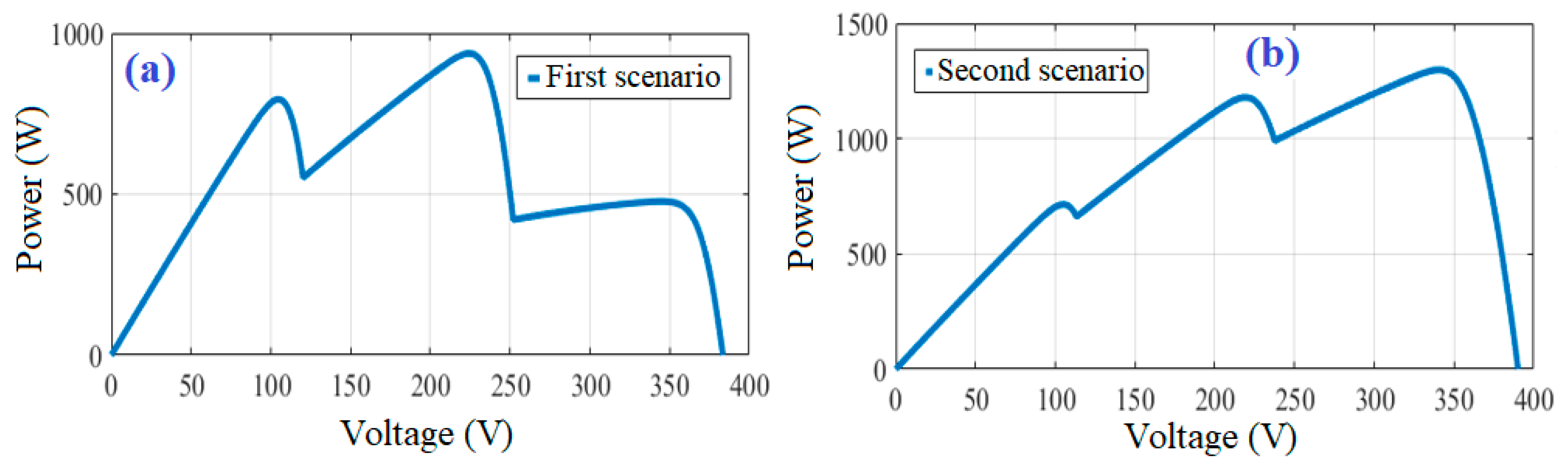
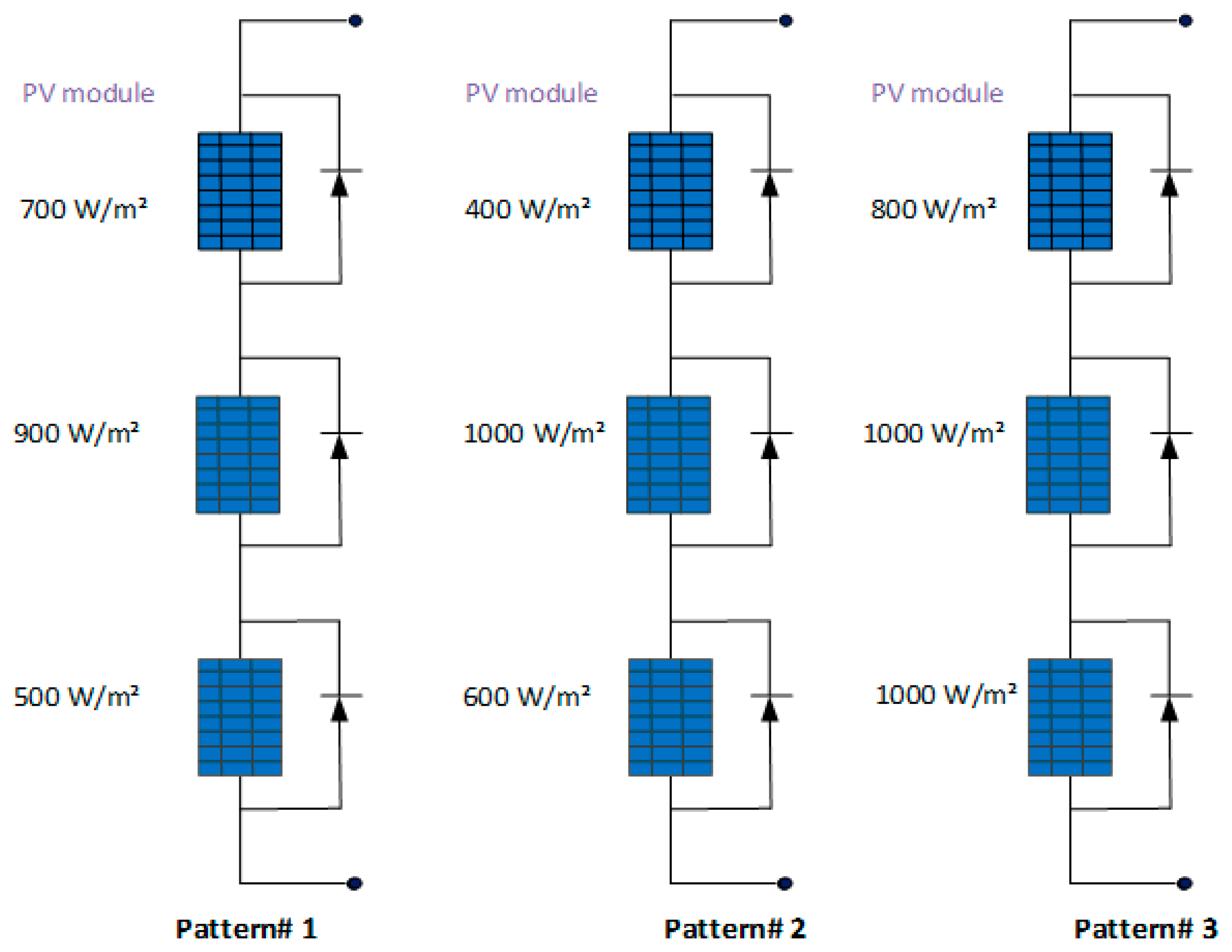
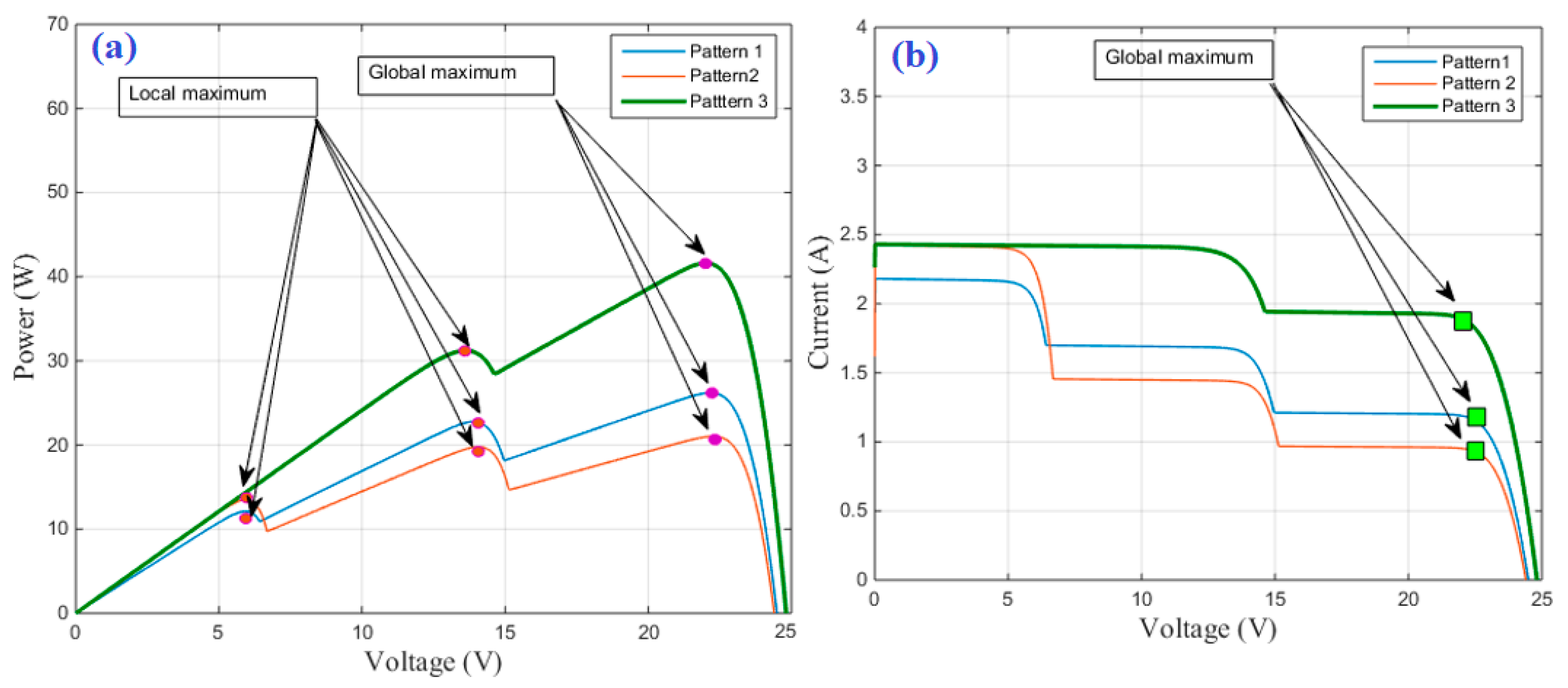
2. Partial Shading Condition

Partial shading condition could occur from the shadow of trees and buildings [44,45]. Fully or partial shadow is considered an essential problem, which minimizes the output power of PV system [46]. Normally, one or three bypass diodes are connected with every PV panel module, in order to overcome the problem of hot-spot phenomena [47]. Under uniform solar irradiance, power versus voltage curve has unique maximum power point (MPP). This point can be easily tracked with any conventional tracking method. This situation is completely different under partial shading condition (PSC). The power versus voltage curve will have several MPPs depending on the number of different solar irradiance levels. Therefore, the conventional tracking methods cannot extract the global point under PSC. Figure 1 shows PV system under three different partial shading patterns. The corresponding P-V and I-V characteristics are shown in Figure 2a,b, respectively. As a result, it was necessary to develop a robust global MPPT control algorithm that allows detection of global MPP under shaded conditions.

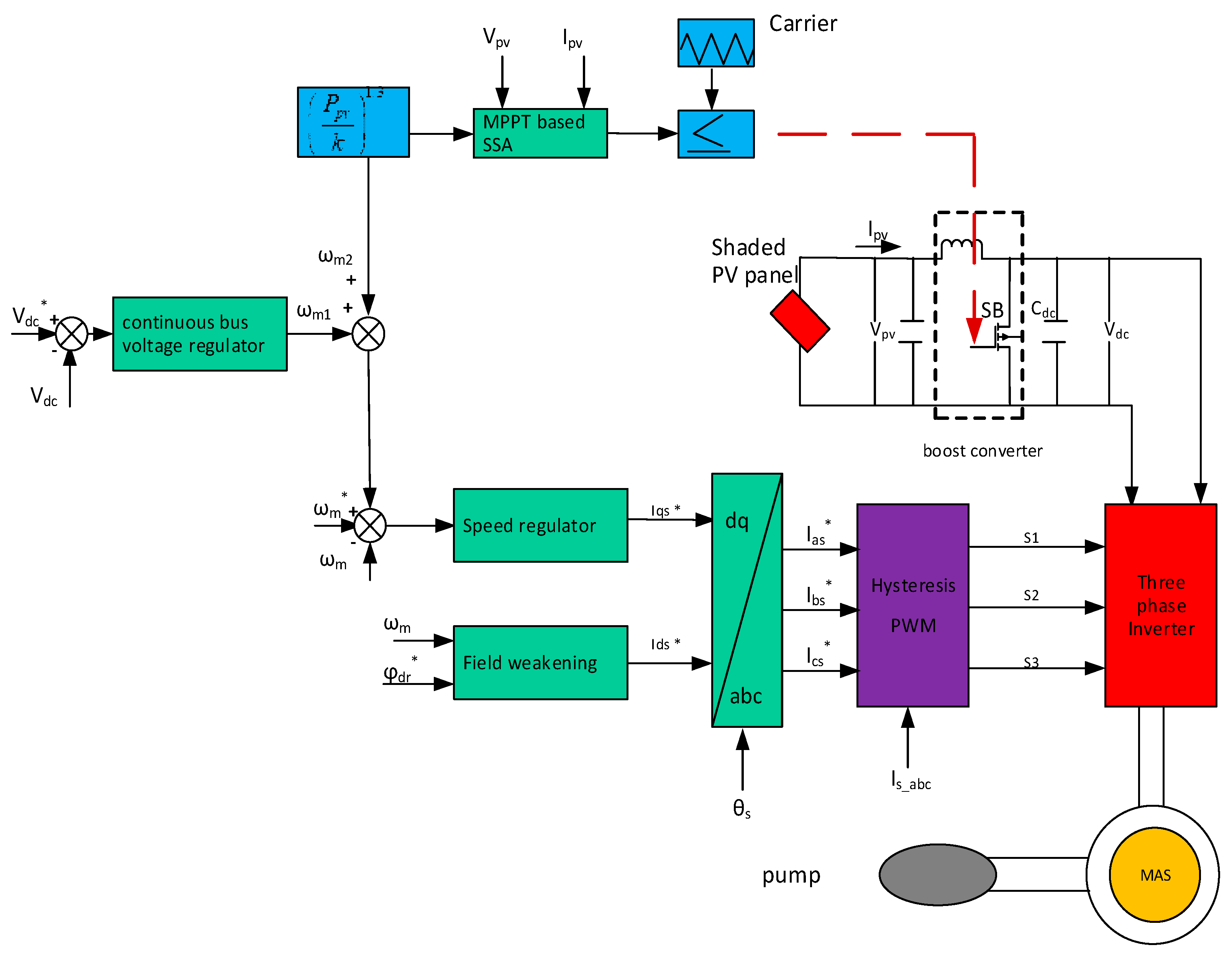
3. Configuration of Proposed PV Pumping System

The suggested system contains the following components: PV array, three-phase inverter, DC-DC converter, asynchronous machine and Centrifugal pump. Figure 3 illustrates a block diagram of the photovoltaic pumping system equipped with MPPT and Indirect Field Oriented Control (IFOC) controls. Referring to this system, many control approaches have been developed for efficient operations in terms of voltage regulation, speed regulation, different MPPT strategies, frequency control, and load variations. The main components of system can be summarized as follows:
(1)
PV panels to supply power the induction motor through a three-phase current inverter (CSI: Current Source Inverter).
(2)
PWM hysteresis technique is used to control the current inverter.
(3)
A DC-DC Boost converter, which ensures the tracking of the global MPP under partial shading conditions through the use of the SSA optimization approach.
(4)
Flux weakening element is needed to generate the reference current ( I d s * ) and the speed regulator output represents ( I q s * ).
(5)
A motor pump driven by vector control [48].
(6)
The reference speed is a function of the photovoltaic power coming from the MPPT control bloc and the DC bus voltage controller, type (PI).
In the PI controller’s framework, the appropriate values of the gain’s controllers ( k p s , k i s , k p d c , k i d c ) are generally obtained by trials and errors procedure. This non-systematic and hard mechanism is often becoming more difficult and time-consuming in the control design stage of VSI (Voltage Source Inverter).

3.1. Modeling of the Asynchronous Machine

When allowing for the asynchronous machine modeling, the Park transform is adopted, this choice makes it possible to directly appreciate the current module, thus facilitating regulation [49].
V d s = R s I d s + σ L s d I d s d t + L m L r d φ d r d t ω s σ L s I q s
V q s = R s I q s + σ L s d I q s d t + ω s L m L r φ d r + ω s σ L s I d s
V d r = 0 = R r L r φ d r + d φ d r d t L m L r R r I d s
V q r = 0 = ω s l φ d r L m L r R r I q s
where σ = 1 L m 2 L s L r , V d s , V q s , V d r and V q r are respectively the stator and the rotor voltages. I d s and I q s indicate the stator currents.
φ d r = L m I m d r
I d s = I m d r + L r R r d I m d r d t
I d s = ( 1 + p . τ r ) I m d r
where τ r = L r R r
In   steady   states   conditions   I d s = I m d r
The instantaneous calculation of the angle θ s is based on this equation:
θ s = ω s d t
θ s = ω s d t = ( ω s l + ω r ) d t
The sliding speed ω s l can be obtained by the following equation [49]:
ω s l = L m L r R r φ d r I q s = L m I q s τ r φ d r = I q s τ r I m d r
In steady states conditions ( I m d r = I d s )
ω s l = I q s τ r I d s
Equations (13) and (14) can be used to calculate the reference flux and reference stator current, respectively [45]:
φ d r * = { φ r n s i | ω m | ω m n φ r n ω m n | ω m | s i | ω m | > ω m n
where φ r n : Nominal value of flux and ω m n : Nominal value of mechanical speed
I d s * = φ d r * L m
L m : is the mutual inductance
I q s * = T e * / 3 2 P L m 2 L r φ d r *
The correlation between the torque and the speed as expressed through the pump model, is equal to [50]:
T r = a 1 + a 2 . ω m 2
where a1, a2 are the constants of the pump. T r and ω m are respectively the torque and the speed of the pump.
The power has a parabolic relationship with the motor speed ω m , thus actuating as the centrifugal pumps [51,52].
In this system framework, the affinity law has been applied to evaluate one of the components of the reference speed. Therefore, the motor operates under the solar irradiation variation and determines the flow rate of the centrifugal pump. In fact, for optimizing the PV output power, we have developed an MPPT control, which allows extracting the global MPP from the PVS under PSC, using the optimization approach SSA. The power generated, thus contributes to the calculation of the first component of the reference speed, according to the following formula [53]:
ω m 1 = ( P p v k ) 1 / 3
The photovoltaic power is converted in terms of speed via the constant k.
The DC bus voltage controller is utilized to evaluate the second part of the reference speed. In this system, the detected bus voltage ( V d c ) is compared with the reference bus voltage ( V d c * ) and leads to a voltage error, defined as [54];
V d c l ( n ) = V d c * ( n ) V d c ( n )
This error signal passes through the voltage regulator, type (PI) and the resulting output speed is given by this formula [50]:
ω m 2 ( n ) = ω m 2 ( n 1 ) + K p d c { V d c l ( n ) V d c l ( n 1 ) } + K i d c . V d c l ( n )
where k p d c and k i d c are respectively the proportional and integral gains of the DC bus voltage regulator.
The losses of the system are recorded at the output of this controller.
Therefore, the reference speed of the engine is derived from the following formula [54]:
ω m * = ω m 1 + ω m 2
where ω m * is the reference speed ω m 1 is the first component of reference speed, calculated from Equation (17).
ω m 2 is the second component of reference speed, calculated from Equation (19).

3.2. Modeling of Centrifugal Pump

The mechanical model of the asynchronous motor driving the pump is given by the following equation [55]:
T e T r f ω m = J d ω m d t
T e , T r indicate respectively the electromagnetic torque and the load torque (pump characteristic), J: is the moment of inertia, f: is the dumping coefficient. The pump can be modeled by the following relation [53]:
T r = A p ω m 2
where Ap is the torque constant, given by equation [53]:
T r = A p ω m 2
where Pn is the rated power of induction motor and ω m n is the rated speed.

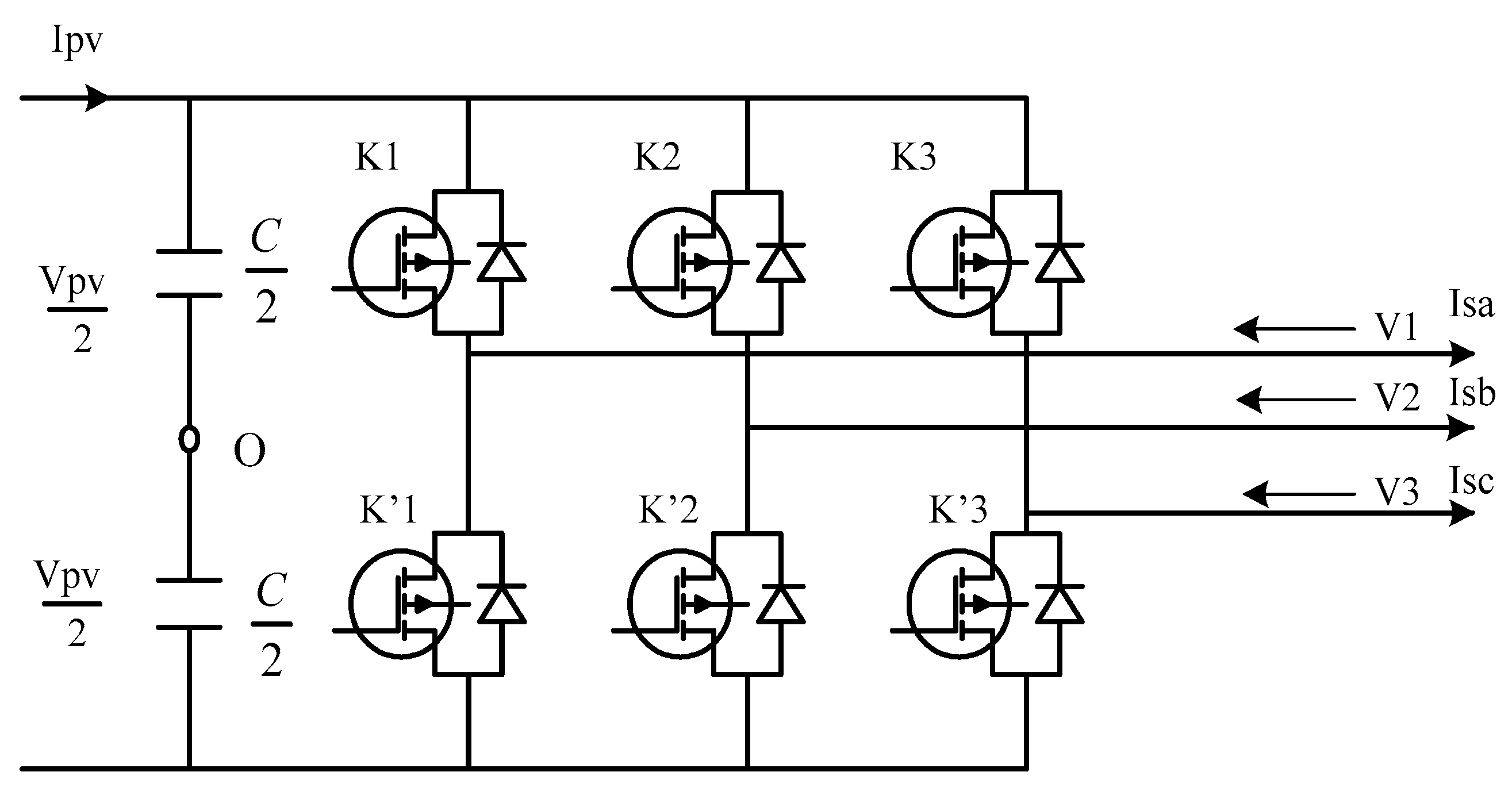
3.3. Three Phase Inverter

In addition to photovoltaic modules, a PV system requires other components to interact efficiently and safely with the power grid. In this context, the use of the inverter is important in order to ensure control of power flow between the source and the asynchronous machine. The current inverter used has three independent arms, as described in Figure 4.
We are interested in the family of the DC-AC converters, which are applied in the field of solar energy and more especially to three phase current converters. Thus, this current inverter enables alternating currents to be generated from the renewable source, forming a balanced three-phase system. The modeling of the inverter depended on the state of the switches. Thus, we must use a continuous equivalent model of this device. The system of simple voltages is then written in the following matrix form [56]:
[ V 1 V 2 V 3 ] = V p v 3 [ 2 1 1 1 2 1 1 1 2 ] [ K 1 K 2 K 3 ]
At all times, the current supplied by the DC power source obeys to;
I p v = K 1 I s a + K 2 I s b + K 3 I s c
These power electronic converters are controlled by PWM hysteresis technique.

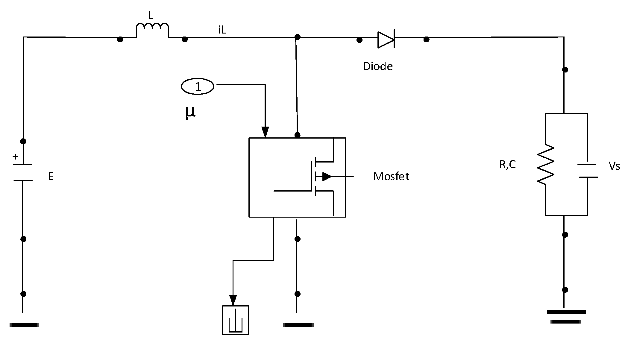
3.4. DC-DC Boost Converter

Figure 5 illustrates the ideal DC-DC Boost converter scheme. It is powered by a DC voltage source E from the photovoltaic solar panels. The circuit is driven through the duty cycle of MOSFET, which is controlled by pulse with modulation (PWM).
The input voltage E is proportional to the output voltage:
V s = E 1 u
where u is the duty cycle.
In this area, the introduction of the MPPT algorithm is therefore necessary to maximize the Boost converter’s energy efficiency.

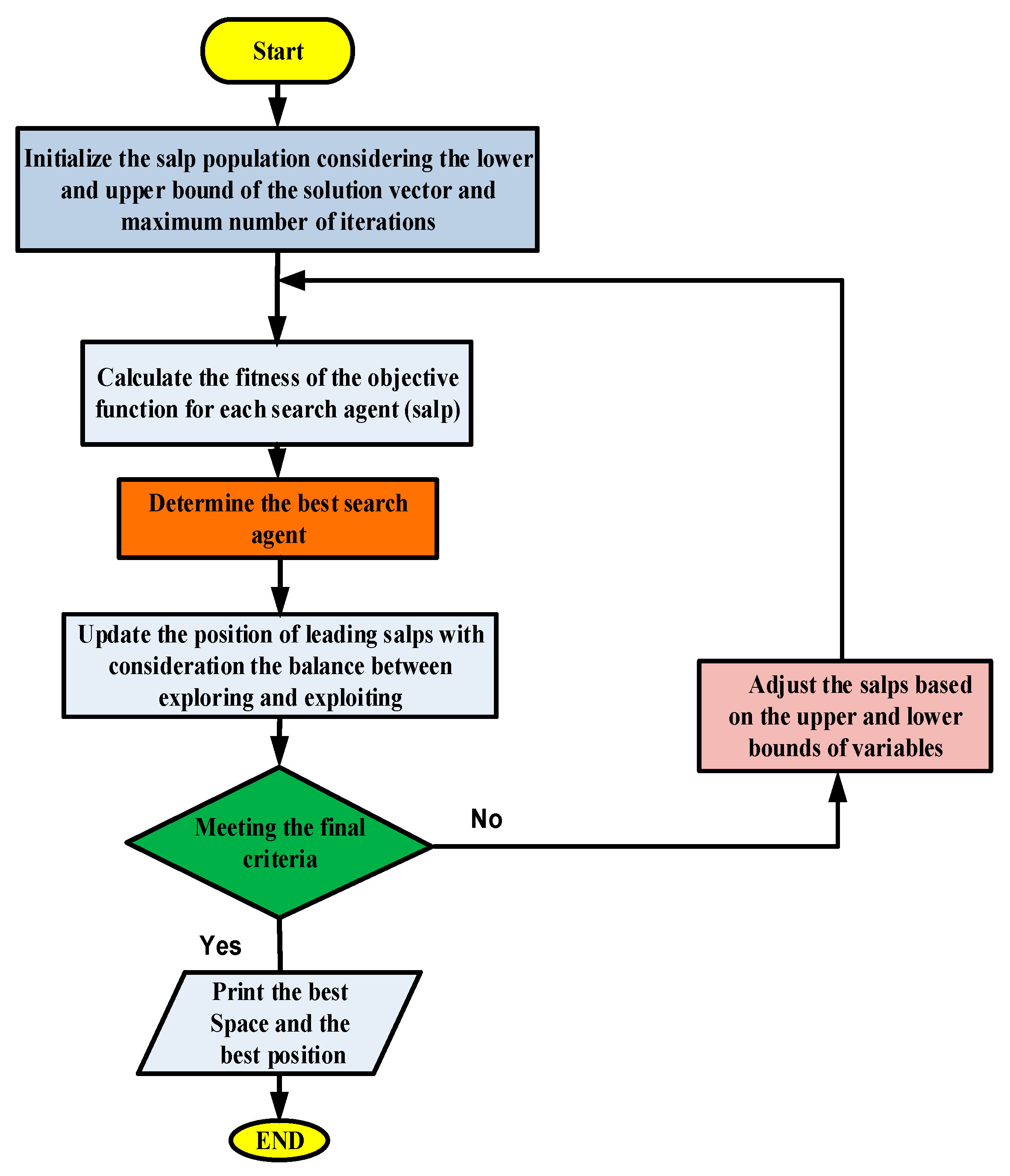
3.5. GMPP Based Salp Swarm Algorithm

Motivated by exploration and foraging attitude of salp in the deep ocean, Mirjalili et al. [57] reported a novel optimization technique, named SSA. These creatures form a close chain called swarm or salp chain. This chain comprises a leader salp and a group of followers, which attempt to find the best region of food via this search method. Likewise, the algorithm is initialized with an initializing matrix of n × dim, which represents salps’ positions, where n denotes the agents and dim is the decision variables. This is a recursive process, where the position of each salp is updated, as per the information given by the leader, for devouring the best food (F). The updated formula for salps’ positions is reported in [44], and is presented as,
x j 1 = F j + c 1 ( ( u b j l b j ) c 2 + l b j ) c 3 0 x j 1 = F j c 1 ( ( u b j l b j ) c 2 + l b j ) c 3 < 0
where, x j 1 denotes the position of the first salp (leader) in the j-th dimension, F j is the position of the food source in the j-th dimension, u b j reveals the upper bound of j-th dimension, l b j reveals the lower bound of j-th dimension, c 2 and c 3 are random values. c 1 can be described as the following;
c 1 = 2 e ( 4 l L ) 2
where, l is the current iteration and L is the maximum number of iterations. To update the position of the followers, the following equations is applied (Newton’s law of motion),
x j i = 1 2 a t 2 + v 0
where, i ≥ 2, x j i represents the position of i-th salp in j-th coordinate, t is the time, v 0 is the initial speed, and a = v f i n a l v 0 where v = x x 0 t . Since the optimization is an iterative process, the discrepancy between iterations is equal to 1, and considering v 0 = 0 , this equation can be reformulated as follows:
x j i = 1 2 ( x j i + x j i 1 )
The main steps of the SSA optimizer are explained in Figure 6. The optimizer starts the process by setting random position for each salp. Then, it estimates the cost function for each salp, finds out the leader salp that has the maximum fitness, and assigns the position of the leader salp as the source food to be chased by the salp string. Next, the new positions for salps are modified. If any of the salp exceeded the search space, it will be recovered on the boundaries. This process continued until the end criteria is achieved.
For the case under study, the duty cycle of DC-DC boost converter has been selected as a decision variable. It is varied from zero to one. Whereas, during the optimization process, the cost function is selected to be the output power from PV system.

3.6. Details of a Case Study

The photovoltaic generation system is composed of a three-phase induction motor drive of 2200 W, 230 V, used to feed the pump, which is powered by 2400 W maximum solar PV array. The specifications of PV array, PV module and the parameter of induction motor are shown in Table 1, Table 2 and Table 3, respectively.
Two different scenarios of partial shading are considered. In the first case, the solar irradiances are 1.0 KW/m2, 0.55 KW/m2, and 0.2 KW/m2. The P-V graph is illustrated in Figure 7a. For this condition, the global maximum power point of 920 W is detected at the second one on P-V curve. The solar irradiances are 0.5 kW/m2, 0.9 kW/m2 and 0.7 kW/m2 in the second presented PSC pattern. The P-V graph is depicted in Figure 7b. Under this case, the global maximum power point of 1284 W is situated at the third point on P-V curve.

4. Results and Discussions

Figure 8 shows the response of PV output power for SSA and P&O methods under considered shading scenarios. For the first scenario, SSA based tracker succeed to catch the global power of 920 W accurately. On the contrary, the conventional P&O-MPPT tracker failed in attaining the global MPP and reached the local MPP of 475 W. This means that the harvested power is increased by 93.68% by using SSA based tracker compared with using P&O based tracker.
The detailed performance (power, voltage, speed, load torque, etc.) of the PV system fed water pumping system, obtained with the SSA-MPPT strategy under the first shading pattern, are illustrated in Figure 9. Figure 10 illustrates the detailed performance of the system with using P&O method.
Referring to Figure 9 and Figure 10, the load torque by using SSA is 7 N.m whereas, equal to 4.8 N.m via P&O. This means it is increased by 45.83%.
For the second shading scenario, the global MPP of 1284 W is situated at the third point on the P-V curve, as illustrated in Figure 7b. Considering Figure 8b, it is observed that, P&O-MPPT cannot achieve global MPP. This tracks the second local MPP of 1020 W. This mean that the harvested power is increased by 25.88% by using SSA based tracker compared with using P&O based tracker.
The detailed performance (power, voltage, speed, load torque, etc.,) of the proposed PV array fed water pumping system, obtained with the SSA-MPPT strategy under the second shading pattern are illustrated in Figure 11. Figure 12 illustrates the detailed performance of the system with using the P&O method.
In sum, MPPT control method based on SSA converges rapidly towards the global MPP, which results in fast detection under partial shading patterns with high efficiency in terms of speed convergence and steady state performance. It has been found that the reference and measured values of the rotor speed converge towards the nominal value, which has proven improved efficiency of the speed regulation. Since load torque is a component of rotor speed, the chances of water spilling out of the pump decreases due to sudden torque variation in the proposed control method. Figure 9d shows the impact of torque at 0.1 s with an increase in rotor speed and achieves steady state at 3.5 s. Figure 10d and Figure 12d clearly depict that the output torque changes as rotor speed changes subjected to changing radiation.
In addition, refereeing to the obtained results, it is observed that the P&O-MPPT tracker failed to catch the global MPP under two studied shading patterns because of disability to differentiate the local MPP from the global one. As a result, the performance of the SSA-MPPT controller is proven to be better than the P&O-MPPT controller in terms of tracking speed under different studied shading pattern. To certify the obtained results through SSA method and to assure that it is not coming by chance, the SSA algorithm was run 50 times and compared with well-known algorithms; particle swarm optimization (PSO) and genetic algorithm (GA). The successful rate is used as a benchmark for the comparison. The successful rate is known as the percentage of no. of fulfilling the true global MPP to the total no. of iterations. For the first shading scenario, the successful rate values are 82%, 86%, and 98% respectively for PSO, GA, and SSA. Whereas, it is 74%, 88%, and 96%, respectively for PSO, GA, and SSA for the second shading scenario. This ensures the superiority of SSA compared with PSO and GA

5. Conclusions

The application of modern optimization is used to promote the performance of solar photovoltaic array fed water pumping system (SPVWPS) under partial shading. Salp Swarm Algorithm (SSA) based global MPPT technique is compared with the classical perturb and observe (P&O) method for partially shaded SPVWPS. Different scenarios of shadow have been considered.
The main findings can be summarized as follows:
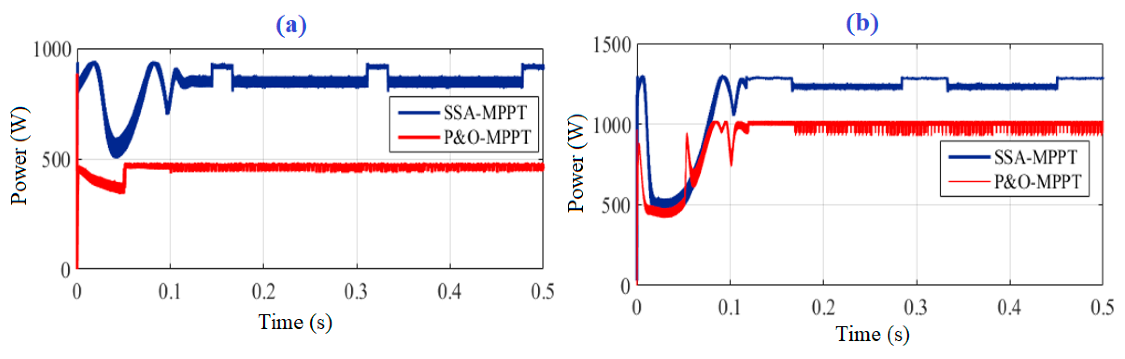
  • During the first shading scenario, the PV output power and pump torque are increased by 93.68% and 45.83%, respectively by using SSA based tracker compared with using P&O based tracker.
  • During the second shading scenario, the PV output power is increased by 25.88% using SSA based tracker compared with using P&O based tracker.
  • The superiority of SSA compared with particle swarm optimization (PSO) and genetic algorithm (GA) is proved.
Finally, SSA method can be considered time-consuming in the case of normal condition. Therefore, a combined MPPT algorithm, consisting of a P&O approach and an SSA, to reach high adaptability at different environmental conditions, will be taken into consideration in future work.

Author Contributions

Conceptualization, J.A. and H.R.; methodology, J.A. and H.R.; software, J.A., H.R. and M.A.-D.; formal analysis, J.A., F.E., M.A. and H.R.; investigation, J.A., F.E., M.A.-D., M.A. and H.R.; resources, J.A, M.A.-D. and H.R.; writing—original draft preparation, J.A., F.E., M.A.-D., M.A. and H.R.; writing—review and editing, J.A., F.E., M.A.-D., M.A. and H.R.

Funding

This research received no external funding.

Conflicts of Interest

The authors declare no conflict of interest.

Abbreviations

ACAlternating Current
CSICurrent Source Inverter
DCDirect Current
GAGenetic Algorithm
GMPPGlobal Maximum Power Point
IFOCIndirect Field Oriented Control
IRFOCIndirect Rotor Field Oriented Control
IMDInduction Motor Drive
MPPMaximum Power Point
MPPTMaximum Power Point Tracking
PSCPartial Shading Conditions
PSOParticle Swarm Optimization
PSO-MPPTMaximum Power Point Tracking based Particle Swarm Optimization
PVPhotovoltaic
P-VPower-Voltage
P-IPower-Current
PWMPulse Width Modulation
P&OPerturb and Observe
SPIMSingle Phase Induction Motor
SPWPSSolar Photovoltaic Water Pumping System
SPVSolar Photovoltaic
SSASalp Swarm Algorithm
SSA-MPPTMaximum Power Point based Salp Swarm Algorithm
VSIVoltage Source Inverter

References

  1. Marmoush, M.M.; Rezk, H.; Shehata, N.; Henry, J.; Gomaa, M.R. A novel merging Tubular Daylight Device with Solar Water Heater—Experimental study. Renew. Energy 2018, 125, 947–961. [Google Scholar] [CrossRef]
  2. Al-Dhaifallah, M.; Nassef, A.M.; Rezk, H.; Nisar, K.S. Optimal parameter design of fractional order control based INC-MPPT for PV system. Sol. Energy 2018, 159, 650–664. [Google Scholar] [CrossRef]
  3. Rezk, H.; Fathy, A. A novel optimal parameters identification of triple-junction solar cell based on a recently meta-heuristic water cycle algorithm. Sol. Energy 2017, 157, 778–791. [Google Scholar] [CrossRef]
  4. Fathy, A.; Rezk, H. Parameter Estimation of Photovoltaic System Using Imperialist Competitive Algorithm. Renew. Energy 2017, 111, 307–320. [Google Scholar] [CrossRef]
  5. Rezk, H.; Dousoky, G.M. Technical and economic analysis of different configurations of stand-alone hybrid renewable power systems—A case study. Renew. Sustain. Energy Rev. 2016, 62, 941–953. [Google Scholar] [CrossRef]
  6. Rezk, H.; Shoyama, M. Techno-economic optimum sizing of stand-alone photovoltaic/fuel cell renewable system for irrigation water pumping applications. In Proceedings of the IEEE International Conference on Power and Energy (PECon), Kuching, Malaysia, 1–3 December 2014; pp. 182–186. [Google Scholar]
  7. Rezk, H. A comprehensive sizing methodology for stand-alone battery-less photovoltaic water pumping system under the Egyptian climate. Cogent Eng. 2016, 3. [Google Scholar] [CrossRef]
  8. Rezk, H.; El-Sayed, A.H.M. Sizing of a Stand Alone Concentrated Photovoltaic System in Egyptian Site. Int. J. Electr. Power Energy Syst. 2015, 45, 325–330. [Google Scholar] [CrossRef]
  9. Rezk, H.; Tyukhov, I.; Al-Dhaifallaha, M.; Tikhonov, A. Performance of data acquisition system for monitoring PV system parameters. Measurement 2017, 104, 204–211. [Google Scholar] [CrossRef]
  10. Rezk, H.; Tyukhov, I.; Raupov, A. Experimental implementation of meteorological data and photovoltaic solar radiation monitoring system. Int. Trans. Electr. Energy Syst. 2015, 25, 3573–3585. [Google Scholar] [CrossRef]
  11. Tolba, M.; Rezk, H.; Diab, A.; Al-Dhaifallah, M. A Novel Robust Methodology Based Salp Swarm Algorithm for Allocation and Capacity of Renewable Distributed Generators on Distribution Grids. Energies 2018, 11, 2556. [Google Scholar] [CrossRef]
  12. Rezk, H.; Hasaneen, E.-S. A new MATLAB/Simulink model of triple-junction solar cell and MPPT based on artificial neural networks for photovoltaic energy systems. Ain Shams Eng. J. 2015, 6, 873–881. [Google Scholar] [CrossRef]
  13. Rezk, H.; Eltamaly, A.M. A comprehensive comparison of different MPPT techniques for photovoltaic systems. Sol. Energy 2018, 112, 1–11. [Google Scholar] [CrossRef]
  14. Shukla, S.; Singh, B. Reduced Sensor Based PV Array Fed Direct Torque Control of Induction Motor Drive for Water Pumping. IEEE Trans. Power Electron. 2019, 34, 5400–5415. [Google Scholar] [CrossRef]
  15. Kumar, N.; Singh, B.; Panigrahi, B.K. Integration of Solar PV with Low-Voltage Weak Grid System: Using Maximize-M Kalman Filter and Self-tuned P&O Algorithm. IEEE Trans. Ind. Electron. 2019, 66, 9013–9022. [Google Scholar]
  16. Hamidat, A.B. Small-scale irrigation with photovoltaic water pumping system in Sahara regions. Renew. Energy 2003, 28, 1081–1096. [Google Scholar] [CrossRef]
  17. Liu, Y.C. Global maximum power point tracking algorithm for PV systems operating under partially shaded conditions using the segmentation search method. Sol. Energy 2014, 103, 350–363. [Google Scholar] [CrossRef]
  18. Gao, X.L. Feasibility evaluation of solar photovoltaic pumping irrigation system based on analysis of dynamic variation of ground water table. Appl. Energy 2013, 105, 182–193. [Google Scholar] [CrossRef]
  19. Khatib, T. Deign of photovoltaic water pumping systems at minimum cost for Palestine: A review. J. Appl. Sci. 2010, 10, 2773–2784. [Google Scholar] [CrossRef]
  20. Meah, K.U. Solar photovoltaic water pumping—Opportunities and challenges. Renew. Sustain. Energy Rev. 2008, 12, 1162–1175. [Google Scholar] [CrossRef]
  21. Meah, K.F. Solar photovoltaic water pumping for remote locations. Renew. Sustain. Energy Rev. 2008, 12, 472–487. [Google Scholar] [CrossRef]
  22. Hamrouni, N.J. Theoretical and experimental analysis of the behavior of a photovoltaic pumping system. Sol. Energy 2009, 83, 1335–1344. [Google Scholar] [CrossRef]
  23. Himri, Y.; Malik, A.S.; Stambouli, A.B.; Himri, S.; Draoui, B. Review and use of the Algerian renewable energy for sustainable development. Renew. Sustain. Energy Rev. 2009, 13, 1584–1591. [Google Scholar] [CrossRef]
  24. Gopal, C.M. Renewable energy source water pumping systems—A literature review. Renew. Sustain. Energy Rev. 2013, 25, 351–370. [Google Scholar] [CrossRef]
  25. Periasamy, P.J. A review on development of photovoltaic water pumping system. Renew. Sustain. Energy Rev. 2015, 43, 918–925. [Google Scholar] [CrossRef]
  26. Chandel, S.N. Review of solar photovoltaic water pumping system technology for irrigation and community drinking water supplies. Renew. Sustain. Energy Rev. 2015, 49, 1084–1099. [Google Scholar] [CrossRef]
  27. Feraga, C.-E.; Bouldjedri, A. Performance of a Photovoltaic Pumping System Driven by a Single Phase Induction Motor Connected to a Photovoltaic Generator. Automatika 2016, 57, 163–172. [Google Scholar] [CrossRef]
  28. Sharma, U.; Singh, B.; Kumar, S. Intelligent grid interfaced solar water pumping. IET Renew. Power Gener. 2017, 11, 614–624. [Google Scholar] [CrossRef]
  29. Diab, A.A.Z.; Rezk, H. Global MPPT based on flower pollination and differential evolution algorithms to mitigate partial shading in building integrated PV system. Sol. Energy 2017, 157, 171–186. [Google Scholar] [CrossRef]
  30. Rezk, H.; Fathy, A. Simulation of global MPPT based on teaching–learning-based optimization technique for partially shaded PV system. Electr. Eng. 2017, 99, 847–859. [Google Scholar] [CrossRef]
  31. Rezk, H.; Fathy, A.; Abdelaziz, A.Y. A comparison of different global MPPT techniques based on meta-heuristic algorithms for photovoltaic system subjected to partial shading conditions. Renew. Sustain. Energy Rev. 2017, 74, 377–386. [Google Scholar] [CrossRef]
  32. Rezk, H.; Fathy, A. A Novel Methodology for Simulating Maximum Power Point Trackers Using Mine Blast Optimization and Teaching Learning Based Optimization Algorithms for Partially Shaded PV System. J. Renew. Sustain. Energy 2016, 8. [Google Scholar] [CrossRef]
  33. Mohamed, M.A.; Diab, A.A.Z.; Rezk, H. Partial Shading Mitigation of PV Systems via Different Meta-Heuristic Techniques. Renew. Energy 2018, 130, 1159–1175. [Google Scholar] [CrossRef]
  34. Avila, E.; Pozo, N.; Pozo, M.; Salazar, G.; Domínguez, X. Improved particle swarm optimization based MPPT for PV systems under Partial Shading Conditions. In Proceedings of the IEEE Southern Power Electronics Conference (SPEC), Puerto Varas, Chile, 4–7 December 2017. [Google Scholar]
  35. Liu, Y.; Huang, S.; Huang, J.; Liang, W. A particle swarm optimization-based maximum power point tracking algorithm for PV systems operating under partially shaded conditions. IEEE Trans. Energy Convers. 2012, 27, 1027–1035. [Google Scholar] [CrossRef]
  36. Tey, K.S.; Mekhilef, S.; Seyedmahmoudian, M.; Horan, B.; Oo, A.T.; Stojcevski, A. Improved Differential Evolution-based MPPT Algorithm using SEPIC for PV Systems under Partial Shading Conditions and Load Variation. IEEE Trans. Ind. Inform. 2018, 14, 4322–4333. [Google Scholar] [CrossRef]
  37. Kumar, N.; Hussain, I.; Singh, B.; Panigrahi, B.K. Rapid MPPT for uniformly and partial shaded PV system by using JayaDE algorithm in highly fluctuating atmospheric conditions. IEEE Trans. Ind. Inform. 2017, 13, 2406–2416. [Google Scholar] [CrossRef]
  38. Mohanty, S.; Subudhi, B.; Ray, P.K. A Grey Wolf Assisted Perturb & Observe MPPT Algorithm for a PV System. IEEE Trans. Energy Convers. 2017, 32, 340–347. [Google Scholar]
  39. Mohanty, S.; Subudhi, B.; Ray, P.K. A New MPPT Design Using Grey Wolf Optimization Technique for Photovoltaic System Under Partial Shading Conditions. IEEE Trans. Sustain. Energy 2016, 7, 181–188. [Google Scholar] [CrossRef]
  40. Kumar, N.; Hussain, I.; Singh, B.; Panigrahi, B.K. Single sensor-based MPPT of partially shaded PV system for battery charging by using cauchy and gaussian sine cosine optimization. IEEE Trans. Energy Convers. 2017, 32, 983–992. [Google Scholar] [CrossRef]
  41. Ramasamy, S.; Jeevananthan, S.; Dash, S.S.; Vishnuram, P. A new maximum power tracking in PV system during partially shaded conditions based on shuffled frog leap algorithm. J. Exp. Theor. Artif. Intell. 2017, 29, 481–493. [Google Scholar]
  42. Sundareswaran, K.; Peddapati, S.; Palani, S. MPPT of PV systems under partial shaded conditions through a colony of flashing fireflies. IEEE Trans. Energy Convers. 2014, 29, 463–472. [Google Scholar]
  43. Seyedmahmoudian, M.; Horan, B.; Rahmani, R.; Oo, A.M.T.; Stojcevski, A. Efficient photovoltaic system maximum power point tracking using a new technique. Energies 2016, 9, 147. [Google Scholar] [CrossRef]
  44. Belhaouas, N.; AitCheikh, M.-S.; Agathoklis, P.; Oularbi, M.-R.; Amrouche, B.; Sedraoui, K.; Djilali, N. PV array power output maximization under partial shading using new shifted PV array arrangements. Appl. Energy 2017, 187, 326–337. [Google Scholar] [CrossRef]
  45. Rezk, H. An efficient single-sensor global maximum power point tracking method for partially shaded photovoltaic battery chargers. Int. J. Energy Res. 2019, 43, 8779–8789. [Google Scholar] [CrossRef]
  46. Li, G.; Jin, Y.; Akram, M.W.; Chen, X.; Ji, J. Application of bio-inspired algorithms in maximum power point tracking for PV systems under partial shading conditions—A review. Renew. Sustain. Energy Rev. 2018, 81, 840–873. [Google Scholar] [CrossRef]
  47. Henze, N.; Koirala, B.P.; Sahan, B. Study on MPP mismatch losses in photovoltaic applications. In Proceedings of the European Photovoltaic Solar Energy Conference and Exhibition, Hamburg, Germany, 21–25 September 2009; pp. 3727–3733. [Google Scholar]
  48. Devanshu, A.; Singh, M.; Kumar, N. DSP based feedback linearization control of vector controlled induction motor drive. In Proceedings of the 2016 IEEE 1st International Conference on Power Electronics, Intelligent Control and Energy Systems (ICPEICES), Delhi, India, 4–6 July 2016; pp. 1–6. [Google Scholar]
  49. Hamid KHAN. Field Oriented Control, Application Note Polytechech’ Clermont-Ferrand, 2008.
  50. Devanshu, A.; Singh, M.; Kumar, N. Sliding Mode Control of Induction Motor Drive Based on Feedback Linearization. IETE J. Res. 2018, 1–14. [Google Scholar] [CrossRef]
  51. Kim, S.-H. Maximum torque control of an induction machine in the field weakening region. IEEE Trans. Ind. Appl. 1995, 31, 787–794. [Google Scholar]
  52. Singh, B.; Shukla, S.; Chandra, A.; Al-Haddad, K. Loss minimization of two stage solar powered speed sensorless vector controlled induction motor drive for water pumping. In Proceedings of the IECON 2016—42nd Annual Conference of the IEEE Industrial Electronics Society, Florence, Italy, 23–26 October 2016; pp. 1–6. [Google Scholar]
  53. Salim, D.; Kheldoun, A.; Sadouni, R. Fuzzy indirect field oriented control of dual star induction motor water pumping system fed by photovoltaic generator. Int. J. Eng. Intell. Syst. Electr. Eng. Commun. 2015, 23, 63–76. [Google Scholar]
  54. Singh, S.; Singh, B. Solar PV water pumping system with DC-Link voltage regulation. Int. J. Power Electron. 2015, 7, 72. [Google Scholar] [CrossRef]
  55. Wanzeller, M.A. Current control loop for tracking of maximum power point supplied for photovoltaic array. IEEE Trans. Instrum. Meas. 2004, 53, 1304–1310. [Google Scholar] [CrossRef]
  56. Marouani, R.; Mami, A. Voltage Oriented Control Applied to a Grid Connected Photovoltaic System with Maximum Power Point Tracking Technique. Am. J. Appl. Sci. 2010, 7, 1168–1173. [Google Scholar] [CrossRef]
  57. Mirjalili, S.; Gandomi, A.H.; Mirjalili, S.Z.; Saremi, S.; Faris, H.; Mirjalili, S.M. Salp swarm algorithm: A bio-inspired optimizer for engineering design problems. Adv. Eng. Softw. 2017, 114, 163–191. [Google Scholar] [CrossRef]
Figure 1. Photovoltaic systems (PVS) under different partial shading conditions.
Mathematics 07 01123 g001
Figure 2. (a) Power versus voltage curves (b) current versus voltage curves of PVS under uniform irradiance and different partial shading patterns.
Mathematics 07 01123 g002
Figure 3. Overview of the photovoltaic pumping system equipped with maximum power point tracking (MPPT) and Indirect Field Oriented Control (IFOC) controls.
Mathematics 07 01123 g003
Figure 4. Three-phase current inverter.
Mathematics 07 01123 g004
Figure 5. Schematic of ideal Boost converter.
Mathematics 07 01123 g005
Figure 6. Flow-chart of Salp Swarm Algorithm (SSA).
Mathematics 07 01123 g006
Figure 7. The P-V graphs for each scenario (a) First shading scenario; (b) Second shading scenario.
Mathematics 07 01123 g007
Figure 8. The response of PV output power for SSA and perturb and observe (P&O) MPPT (a) first scenario (b) second scenario.
Mathematics 07 01123 g008
Figure 9. The detailed performance of solar photovoltaic water pumping system (SPVWP) system under first scenario using SSA based tracker. (a) Direct Current (DC) bus voltage; (b) motor speed; (c) electromagnetic torque; (d) load torque; (e) stator currents; (f) swarm position vs. number of iterations.
Mathematics 07 01123 g009
Figure 10. The detailed performance of SPVWP system under first scenario using P&O based tracker. (a) DC bus voltage; (b) motor speed; (c) electromagnetic torque; (d) load torque; (e) stator currents.
Mathematics 07 01123 g010
Figure 11. The detailed performance of SPVWP system under second scenario using SSA based tracker. (a) DC bus voltage; (b) motor speed; (c) electromagnetic torque; (d) load torque; (e) stator currents; (f) swarm position vs. number of iterations.
Mathematics 07 01123 g011
Figure 12. The detailed performance of SPVWP system under second scenario using P&O based tracker. (a) DC bus voltage; (b) motor speed; (c) electromagnetic torque; (d) load torque; (e) stator currents.
Mathematics 07 01123 g012
Table 1. Design of photovoltaic (PV) array.
PV voltage at MPP326 V
PV Power at MPP2400 W
PV current at MPP7.54 A
Number of series connected modules18
Number of parallel connected modules13
Table 2. PV module specifications.
Open circuit voltage 21.6 V
Short circuit current0.64 A
Voltage at maximum power point17.6 V
Current at maximum power point0.58 A
Table 3. Induction motor parameters.
Nominal power: Pn2200 VA
Stator resistance: Rs0.603 Ω
Stator inductance: Ls0.00293 H
Rotor resistance: Rr0.7 Ω
Rotor inductance: Lr0.00293 H
Moment of inertia: J0.011 Kg.m2
Number of poles: P4

