Article

Development of Preform for Simulation of Cold Forging Process of A V8 Engine Camshaft Free from Flash & Under-Filling

1
Department of Mechanical Engineering, Faculty of Engineering, Islamic University of Madinah, Madinah Munawwarra 2351, Saudi Arabia
2
Department of Mechanical Engineering, College of Engineering, King Khalid University, Abha 61421, Saudi Arabia
3
Research Center for Advanced Materials Science (RCAMS), King Khalid University, Abha 61421, Saudi Arabia
4
Forging Research Group, School of Mechanical Engineering, Universiti Sains Malaysia, Engineering, Campus, NibongTebal 14300, Malaysia
5
Department of Mechanical Engineering, University of Malaya, Kuala Lumpur 50603, Malaysia
*
Authors to whom correspondence should be addressed.
Mathematics 2019, 7(11), 1026; https://doi.org/10.3390/math7111026
Submission received: 19 August 2019 / Revised: 25 October 2019 / Accepted: 27 October 2019 / Published: 31 October 2019
(This article belongs to the Special Issue Finite Element Analysis)

Abstract

:
Finite Element Method based techniques apply to a wide spectrum of engineering applications including manufacturing. The flexibility to achieve optimized results by simulations adds another dimension to process-development. The efficiency due to simulation is enhanced many folds for developing desired components by reducing the cost as well as time. This paper investigates cold forging process to be adopted to produce camshafts with a target to minimize flash as well as under filling. These two factors being major problems encountered when cold forging is to be adopted for complex shaped products. The current work is primarily concerned with the development of an optimized preform design for a V8 engine camshaft. The work involved the Solid modeling of the camshaft on AutoCAD and further analyzing the developed model through finite element analysis using Deform 3D. The analysis involved understanding of metal flow, volumetric analysis and die stresses in the forging process. The materials considered for the work-piece and the dies are AISI 8620 and AISI-H-26 respectively. The sample camshaft was taken from a standard Dodge Challenger V8 engine. 10 different cases are analyzed to find out the best possible scenario. It is fund that the stress level for the developed model was very much within the design limit of the material.

1. Introduction

Forging involves deformation of materials under compressive stress and it can be categorized on the basis of temperature of the work-piece. Cold forging generally results in good surface finish, higher accuracy and greater strength [1,2]. The complexity involved in cold forging makes it adopt process layout methodology and thus there is a need for detailed design work [3]. Customers need products with intricate and complex geometry as well as prefigures of tool life, ductile fracture and microstructure. The computerized based finite element analysis tools have been evolving to great extent in terms of computational capabilities to cater the ever increasing demands of the forging design environment. In a study by Kim et al. [4] the numerical simulations using DEFORM-3D/HT were applied to several design stages in cold forging and heat treatment of the helical gear for the automotive steering part. It was found from the simulation results that CAE could be used as an effective and strong tool to improve process design, such as modification of forming defect during forging process, improvement of tool life, and predictions of microstructure and dimensional change during heat treatment after forging. In a study by Deng et al., [5], a sound 3D rigid-plastic FE model of cold rotary forging of a 20CrMnTi alloy spur bevel gear has established utilizing the DEFORM-3D code and showed that it could be an effective tool in forging analyses. Ku [6] proposed a two stage cold forging for drive shaft with a forward extrusion for preform. The results indicated that the method could be well used to the production f drive shaft. In another study, Huang and Hsia [7] developed a process to avoid the crack formation during cold forging of gas fittings. The investigation of cold forging of a hollow ball in a single step was reported by Samolyk and Winiarski [8]. They revealed that a very narrow range billet dimensions exists for acceptable hollow ball forging.
The conventional methods utilized to manufacture camshafts include casting as well as hot forging, apart from the inherited multitude of machining operations. Cast or Forged camshafts machining is required to achieve final size within the required tolerances. Camshafts are also produced through machining a metal billet from scratch. In case of forging or casting the following machining sequence is still required, turning of the ends & center drilling of the raw casting/forged camshaft, Turning of Journals, Drilling of the dowel hole (required as a reference for further operations), Grinding of journals and Cams, Lapping and Slitting. A relatively new methodology of mass producing camshafts through precision assembly of near-net shaped components on to a tube is also in practice. In this practice the individual components are manufactured by casting, precision warm or cold forging, high speed turning, or powder metal consolidation. The process allows for material selection flexibility to optimize materials for all components with respect to performance and cost. In addition to the inherent advantages of the assembled camshaft, the process typically results in cost advantages over conventionally processed camshafts.
Encouraging results from cold forging techniques have been established for relatively simpler complexity. Samad et al. [9] and Abdullah et al. [10] while studying the AA6061 propeller for AUV application established the conformity of cold forged products with that of FEA simulation. In regards to automotive components a study based on Computer-Aided FE Simulation for flash-less cold forging of connecting rod without under-filling was carried out by Khaleed, et al. [11]. It contained geometry optimization for the preform of an automotive connecting rod to obtain flash-less forging with no under-filling, minimum flash volume and lower forging load. Based on the results the study lined out potential extension of FE analysis for cold forging of automotive components with more intricate geometries. The effect of molybdenum addition on the properties of sinter-forged Fe-Cu-C alloys prepared using elemental powders under various heat treatment conditions was conducted by Rathore et al. [12]. Thus, in line with those studies, FEM based investigation of cold forging process carried out to produce a camshaft (from a V8 engine) through geometry optimization of the preform is undertaken in current study. This work is motivated due to the fact that the geometrical optimization is a critical aspect in the process to control flash generation and eliminating under-filling. In this work, cold forging of the whole camshaft is carried out in a simulation environment based on finite element method to investigate the feasibility of the process and to extract a comparative study of the process under varying mesh refinement. The material considered is AISI 8620, a generic choice for camshafts. The prime difficulties in cold forging of camshafts matches with cold forging of products with intricate, complex and asymmetric geometry. Thus, achieving optimized preform geometry is vital to satisfactory results, in terms of flash formation, under filling, stress distribution etc.

2. Methodology

This section deals with the methodology adopted for preparation and implementation of the finite element approach for the analysis of cold forging of a V8 engine camshaft. A camshaft from a Dodge Challenger V8 engine was selected. The specifications of the camshaft are as shown in the Table 1.
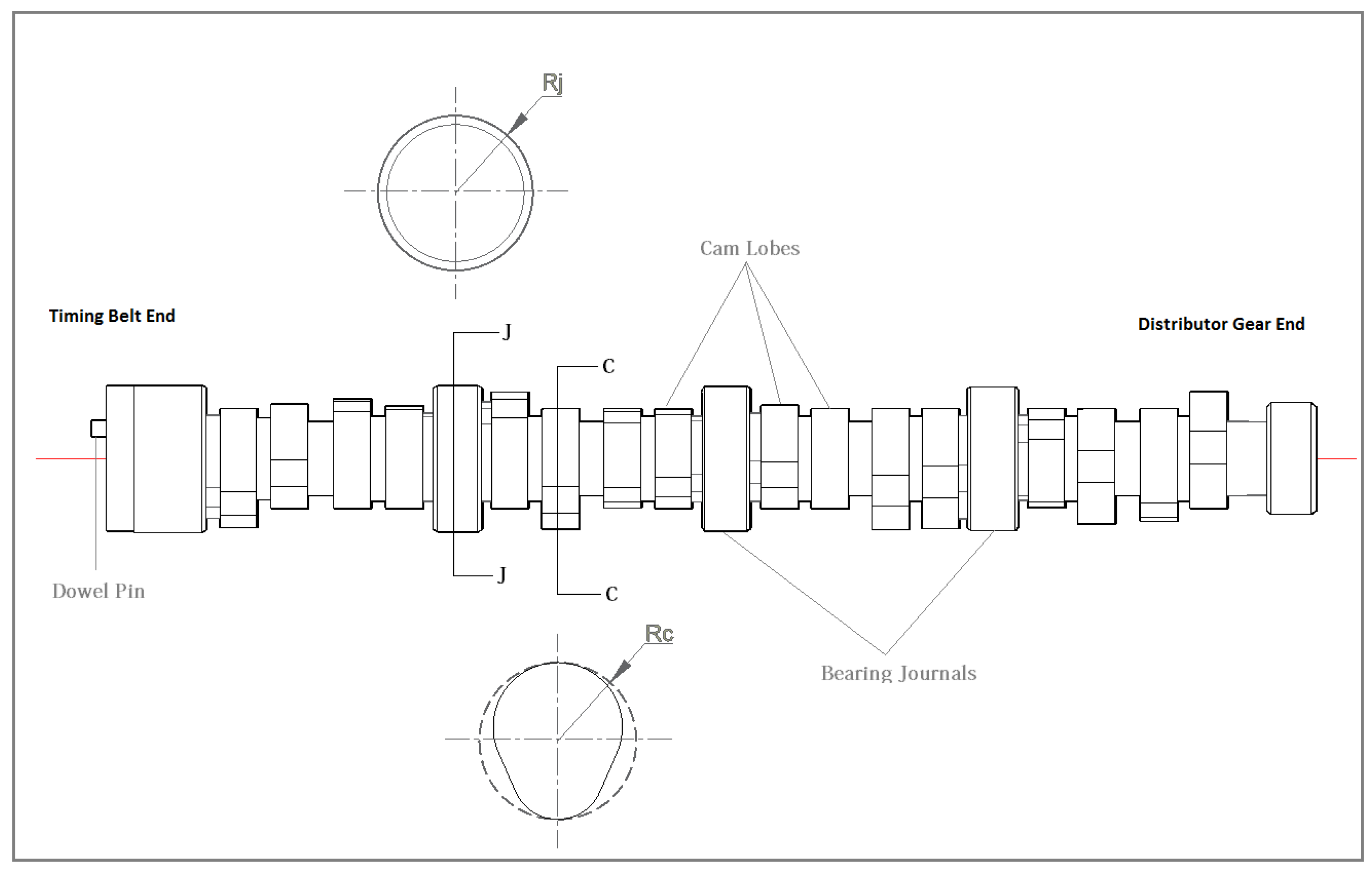
The solid modeling of the camshaft as shown in Figure 1 was completed through lift and angle measurement using dial-gauges. The camshaft was mounted on a lathe with angle indexed headstock. All linear dimensions were taken using vernier calipers.
A flow chart as shown in the Figure 2 depicts the workflow of the study involving post-modeling simulation and geometric analysis in iterative cycles.
The studies on cold forging do not account elastic deformation due to large in process deformation and behavior of work material as rigid plastic. In this study, analysis of deformation was determined by the rigid-plastic FE technique (Deform 3D built-in function) [13]. The pre-form was assumed to obey the Von-misses yield criterion and its associated flow rule, the stress and strain field solutions satisfy the equilibrium equations. The equations related to rigid-plastic FE are as follows [14]:
Equilibrium   Equation : σ ij , j = 0
σ ij , j —actual stress components
Strain rate-velocity relation and incompressibility condition:
ε ˙ ij = 1 2 ( u i , j + u j , i ) ε ˙ v = u i , i = 0
  • ε ˙ ij —strain velocity, u i , j , u j , i , u i , i are deformation velocities
  • ε ˙ —Strain velocity component
Constitutive equations:
σ i j = 2 3 σ ¯ ε ˙ ¯ ε ˙ ij ;   σ ¯ = 3 2 ( σ i j σ i j ) ;   ε ˙ ¯ = 2 3 ( ε ˙ ij ε ˙ ij )
σ i j —Deviatory stress component, σ ¯ and ε ˙ ¯ —effective stress and effective strain velocity, ε ˙ ij —strain velocity
Boundary conditions:
σ ij n i = F j   on   S F ,     u i = U i   on   S U
  • n i —Materials rate of formability change; F j —force on boundary surface S F ; u i —deformation velocity on boundary surface S U
  • S F —Surface on which force applied; S U —deformed surface
The functional mathematical equation for rigid plastic [11]
Π = σ ¯ ε ¯ ˙ d V S F t i v i d S
t i —Traction specified on the boundary S F ; v i —velocity component; dV and dS—volume and surface area of material
Considering a penalty constant K and modifying equation 5, the incompressibility constraints on admissible velocity fields can be removed. Thus, the solution of boundary value problem is obtained from the solution of the dual variation problem, where the first order variation of the functional vanishes.
Π = v σ ¯ δ ε ¯ ˙ d V S F t i δ v i d S + K v ε ˙ v δ ε ˙ v d V = 0
where δ v i —arbitrary variation; δ ε ¯ ˙ and δ ε ˙ v —variations in strain rate from δ v i , ε ˙ v is the volumetric strain rate

2.1. Pre-Form Dimensional Analysis

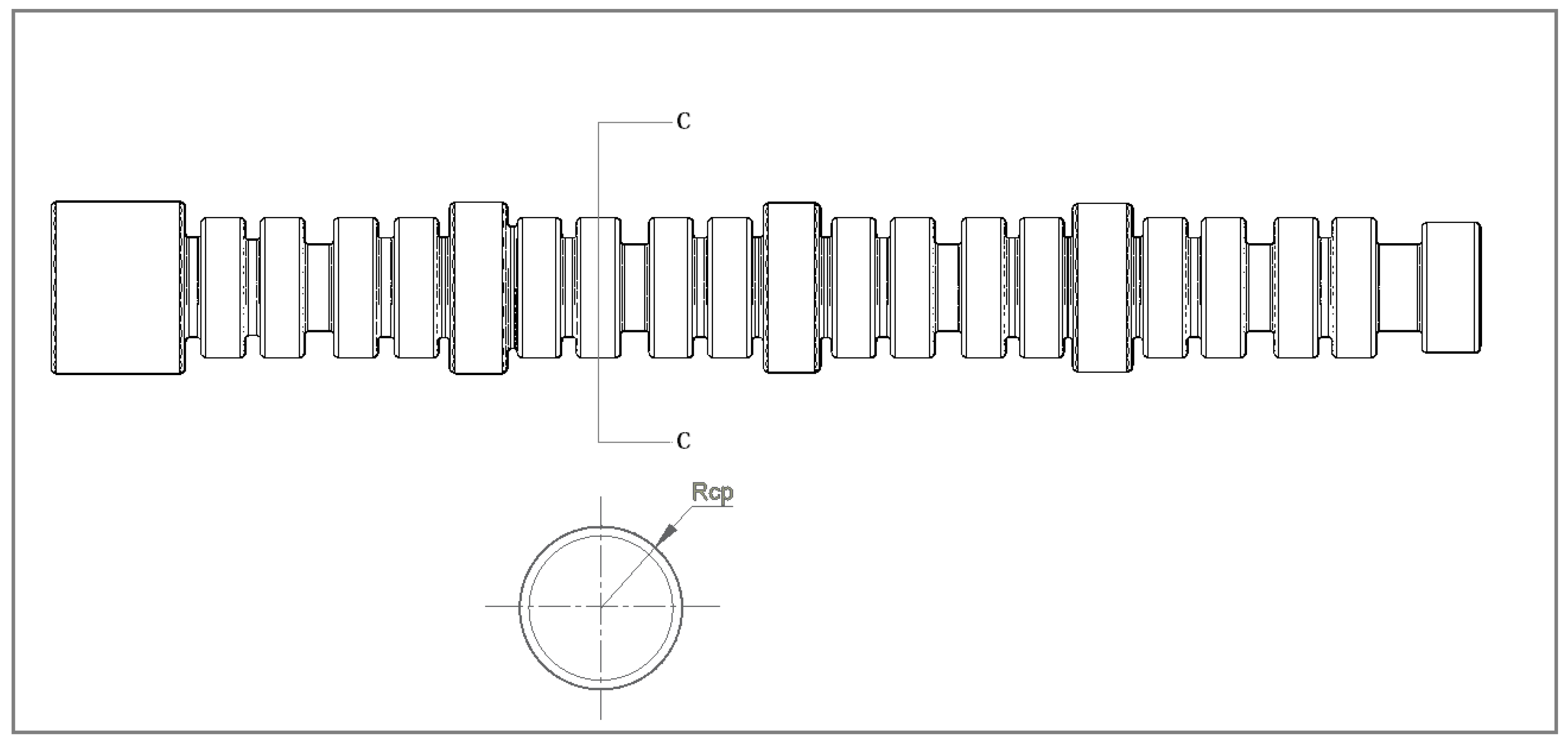
The circular geometric specifics of the preform are kept the same as that of the target. Volume of the finished product and preform must be the same [15]. The volume of the finished product and pre-form specifications can be calculated theoretically as well as through FEA. The volumetric analysis was based on AutoCAD. The first value of the radius of the cams on the preform was calculated from equating the volume of a finished cam and that of the cam on the preform (circular cross-section). Subsequent preforms had equally stepped incremental values of the radius for the cams while keeping all other dimensions unchanged.
V Preform   =   V finished
Rcp—Radius of the cam-lobes in the preform calculated for volume equivalence with the final target values of the cam. This is the minimum Radius for the cam-lobes in the preform and the starting value too. Starting radius value for the journals is taken same as the final target value as the bearing journals are cylindrical. Concerned radii for the target camshaft and the preform are shown in the Figure 3 and Figure 4 respectively. The modeling for punch and die was done based on the target camshaft and allowances were facilitated. The die with flash gutters is shown in the Figure 5. The die blocks were modeled 537 × 108 × 40 mm3 (L × W × H) with 5 mm wide flash gutters.
Based on volumetric and geometrical analysis data, different preforms were obtained by varying the value of Rcp as indicated in Figure 4. The simulations were performed until finished dimensions, flash and under-fill came out satisfactory to the specified application. All other parameters and geometrical information were kept unchanged. It can be noted that the Dowel Pin has not been facilitated in the preform. The optimization strategy adopted in this study was to vary the Rc for different cases and then select the best case based on minimum under-filling and flash along with maximum of 0.01 mm of approach distance between the die and the punch.

2.2. Dimensional Analysis of Cam-Shafts Resulting from Simulations

An important step in the whole process is to analyze the cam-profiles resulting from the simulations so that the resulting cam profiles from the geometry of preforms confirm with the required cam profile geometry. stl files exported from Deform 3D at the end of simulation were imported to AutoCAD for dimensional analysis in terms of the geometry of the cam profile. The results were matched with the required/target geometry. As this analysis is based upon stl files, the comparison in geometry of the cam profiles can only be approximate. The curve-fitting is based upon the periphery projected from one particular triangulated cam-lobe (second cam-lobe from the timing belt end).

2.3. Finite Element Modeling and Material Specification

The Punch, die and the preform were modeled using AutoCAD to obtain the geometry in stl file format that later was taken as an input to Deform 3D.

2.4. Discretization Details

The discretization for the preform, punch and die was kept suitably uniform throughout the different cases of simulation. For example, the number of elements for the case V is shown in the Table 2. Tetrahedral elements were used in the meshing.

2.5. Process Parameters

The process parameter considered for analysis included: initial temperature of pre-form, punch and die temperature (30 °C), punch velocity (125 mm/s), friction co-efficient (0.25). The punch strokes varied with different cases. The simulation process was carried out to stop after a maximum of 0.01 mm of approach distance between the die and the punch. The specifications and material properties being used are given in Table 3.

3. Results

This section presents variation in the preform geometry, dimensional accuracy in the simulation results and selection of an optimal geometry for the preform.

3.1. Volumetric Analysis of Effect of Variation in Preform Geometry

The pivotal matter of interest in the present work was to check the feasibility of producing camshafts involving cold forging techniques. Elimination of under-filling and minimization of flash were of prime concern. This objective of research was addressed through the result of simulations using the forging module of Deform 3D to achieve as optimum geometry for the preform. The simulations indicate that geometry of the preform is of critical significance due to the complexity of the shapes and repetitive barriers to metal flow. Volume based analysis is indicated in the Table 4, whereas profile improvement can be observed in the results with change in radius of the base-circle of the cam-lobes in the preform in Figure 6. An additional parameter, die stopping approach distance affects the volumetric accuracy in the resulting camshaft. Efforts have been made in controlling the simulations to keep this distance to a minimum, the maximum being 0.01 mm.

3.2. Effect of Preform Geometry on Simulation

Ten cases of simulation were carried out with gradual variation in the radius of the cam cylinders in the preform. The geometric analysis was made based on comparison of each case with the target geometry based on the solid model of the camshaft, as shown in the Figure 6. The variation in the preform geometry is shown in the Table 5. The analysis included nearness of the achieved values to the target values in terms of base circle radius and the sectional area of cams. It is evident from Figure 6 that gradual improvement was recorded in the results from Case I to VI but further refinement ceased to occur in subsequent cases up to case X. Among the cases considered, Cases VI to X exhibit neither improvement nor a pattern in terms of the parameters chosen in the geometric analysis. It was necessary that analyses based on under-filling and flash generation as well as forging loads were to be considered to choose preform geometry for further refinement of results or declaration of an optimized result. The data received from this analysis pointed to cases VI and VII as promising.

3.3. Under-Fill and Flash

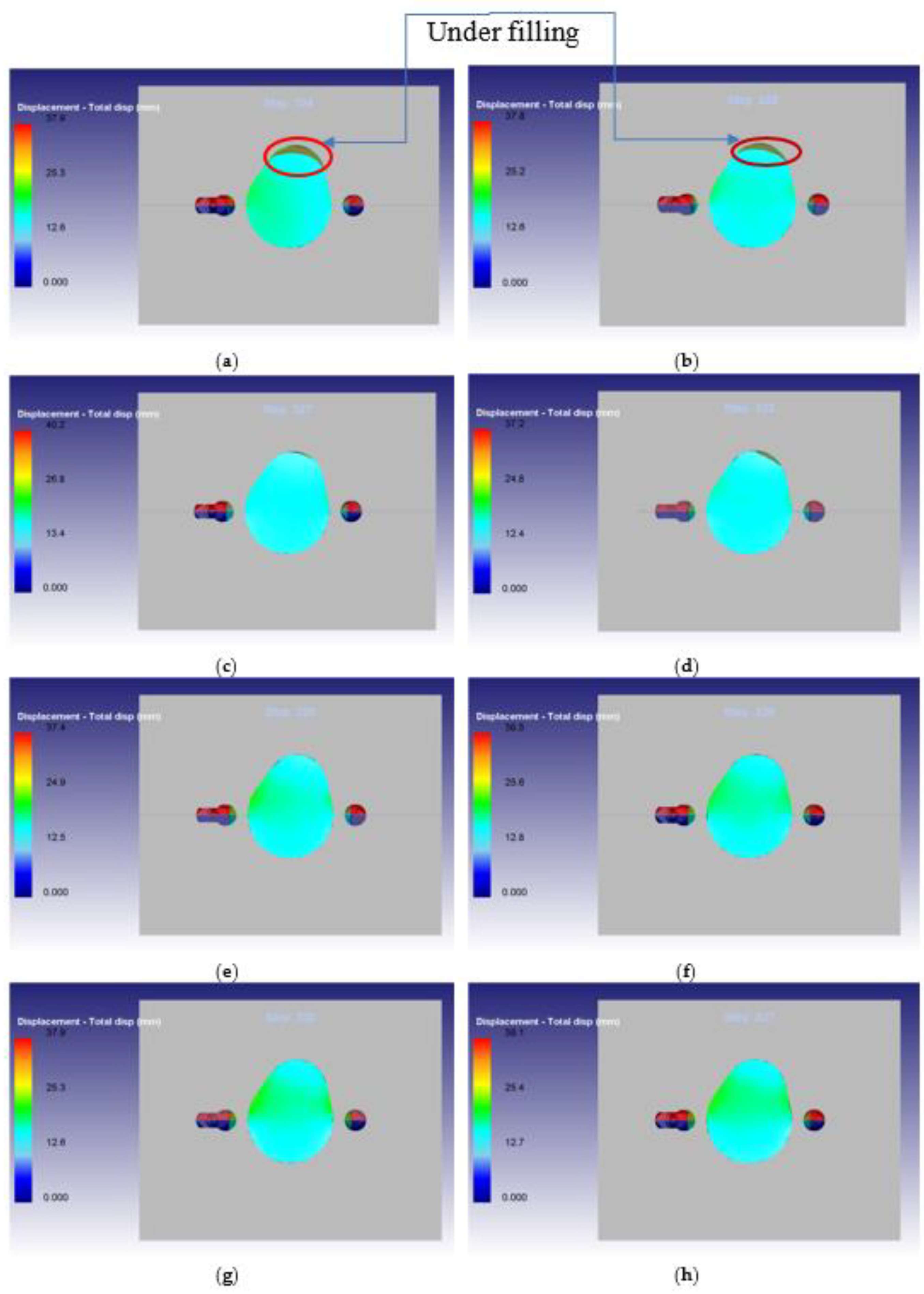
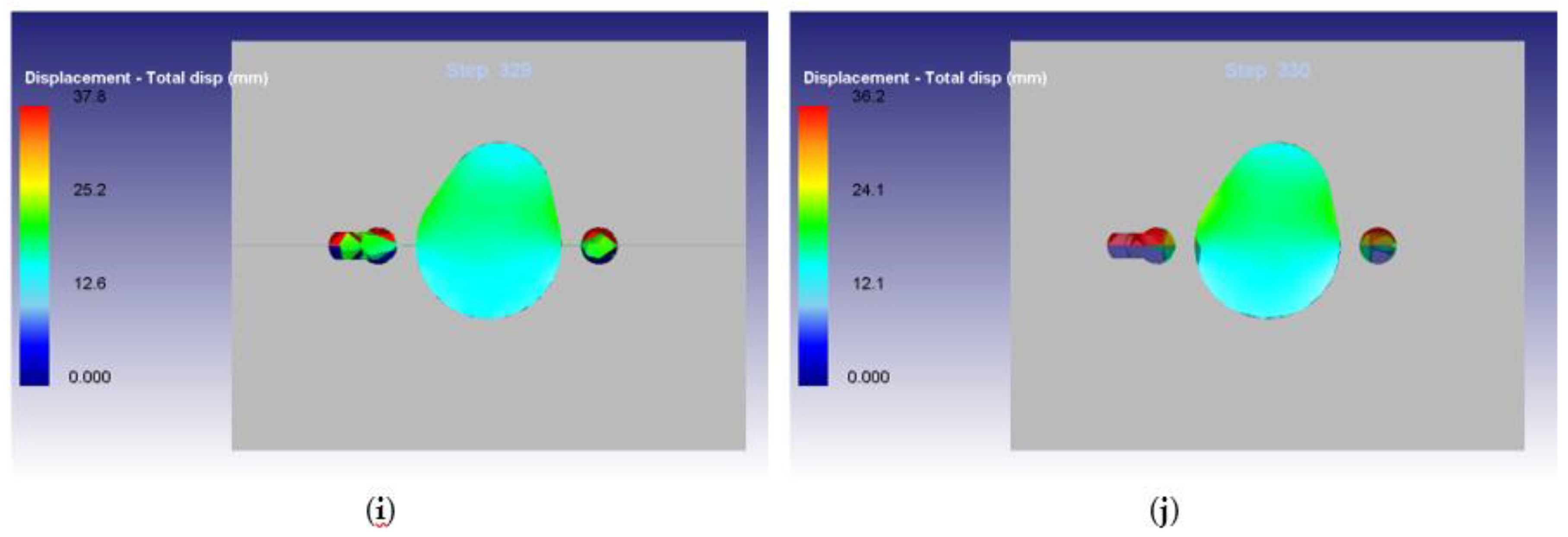
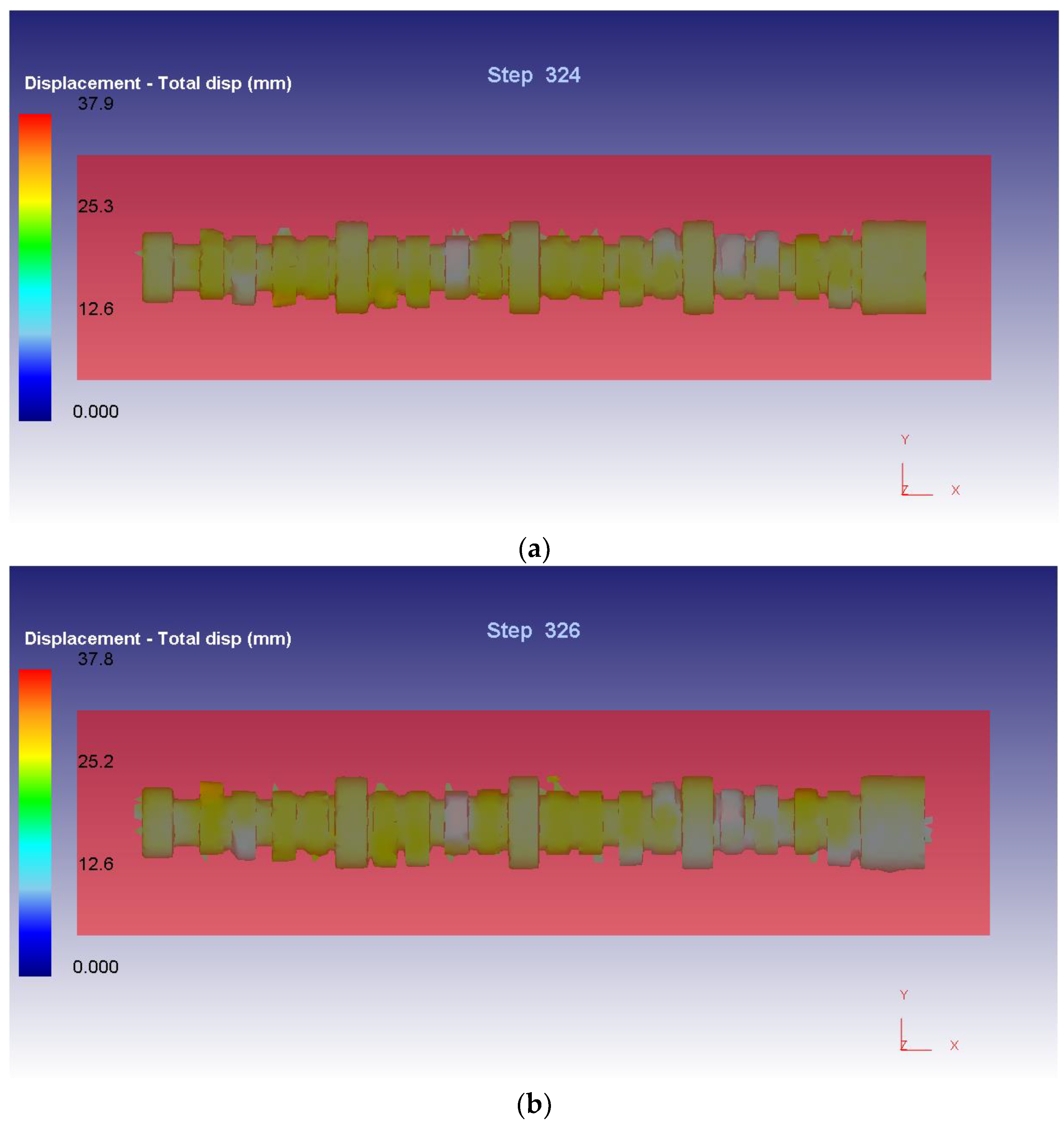
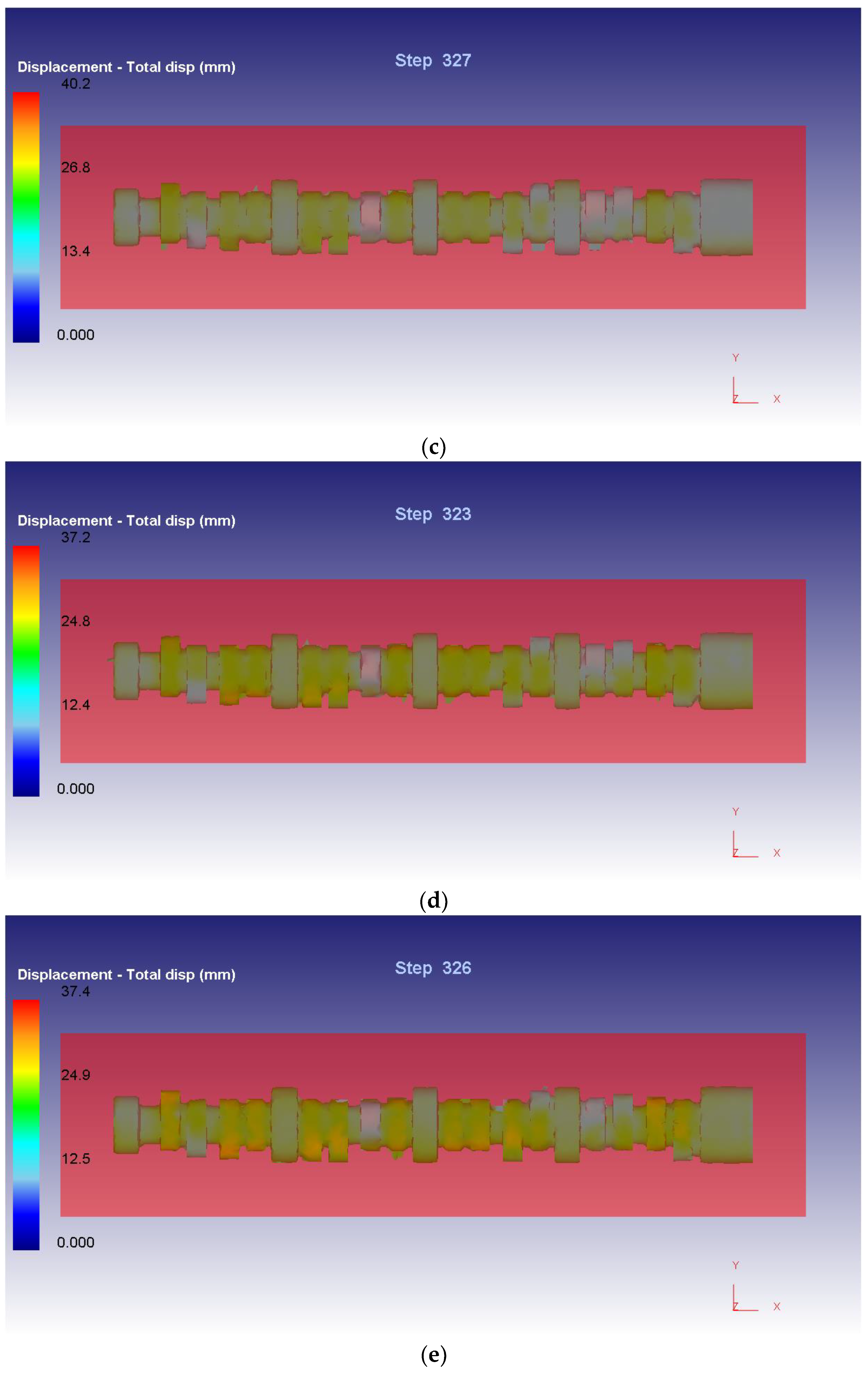
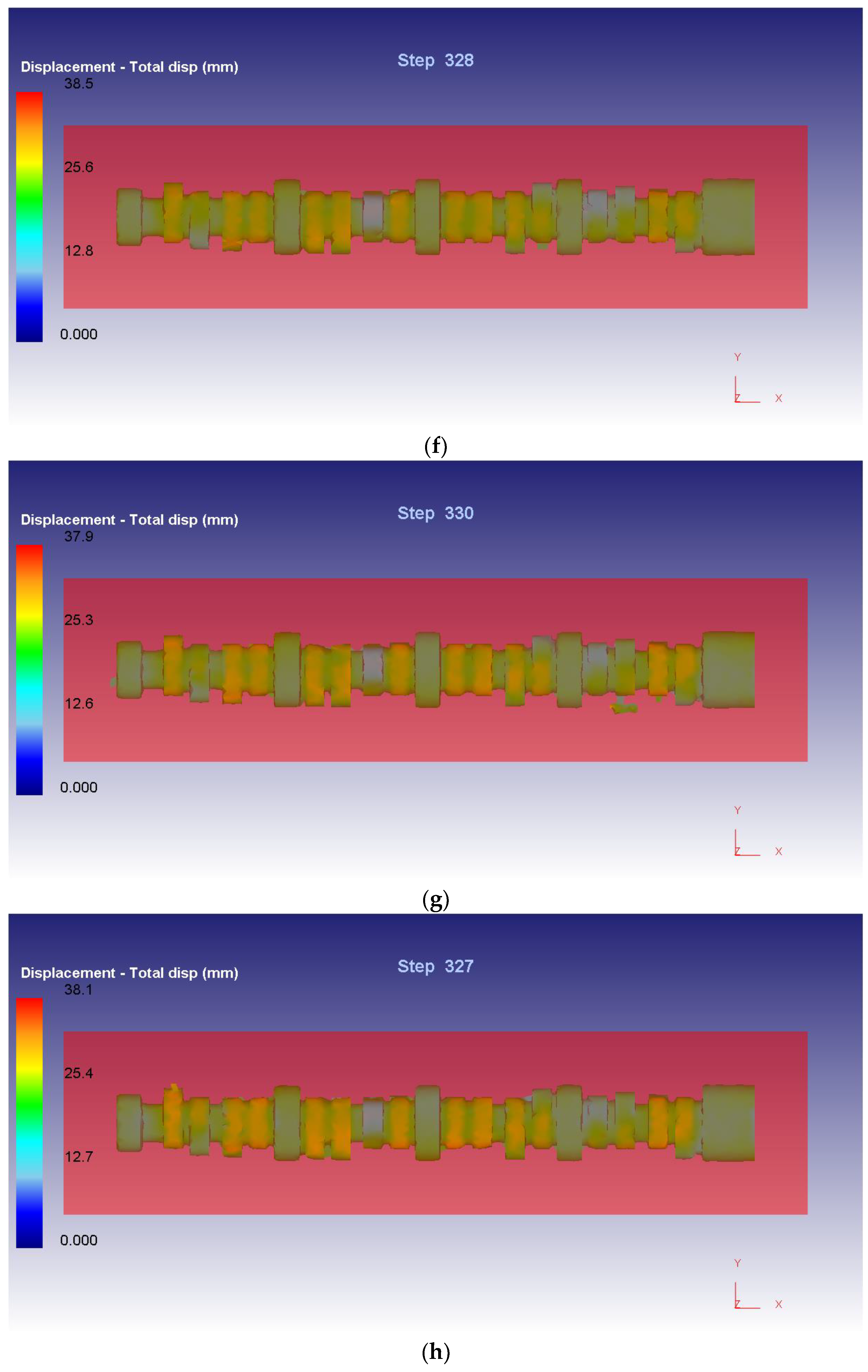
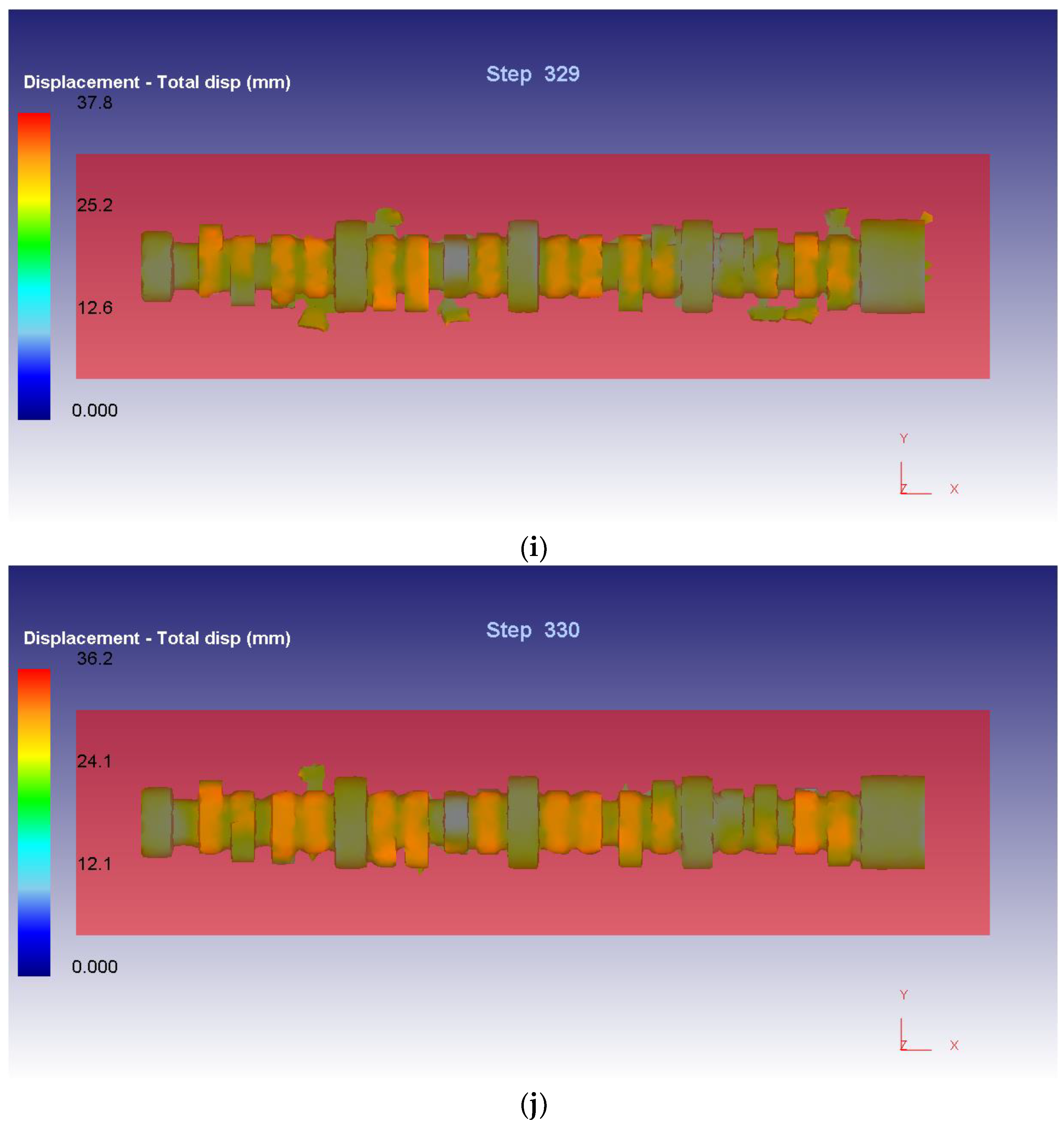
Figure 7 shows presence of cavity/undefiled volume in the dies at an arbitrarily chosen section in the last step of simulation in each case. It may be observed that the cavity volume progressively gets filled up through initial cases and subsequently reduces to a minimal in cases V and beyond, However it reappears in Case X, but at a location irrelevant to the current flow of the study.
Figure 8 shows the presence of flash produced in each case. It may be observed in conjunction with the data shown in Table 4 that the production of flash progressively increases through the cases as is obvious upon increasing the volume of the preform.

3.4. Die Stress Analysis

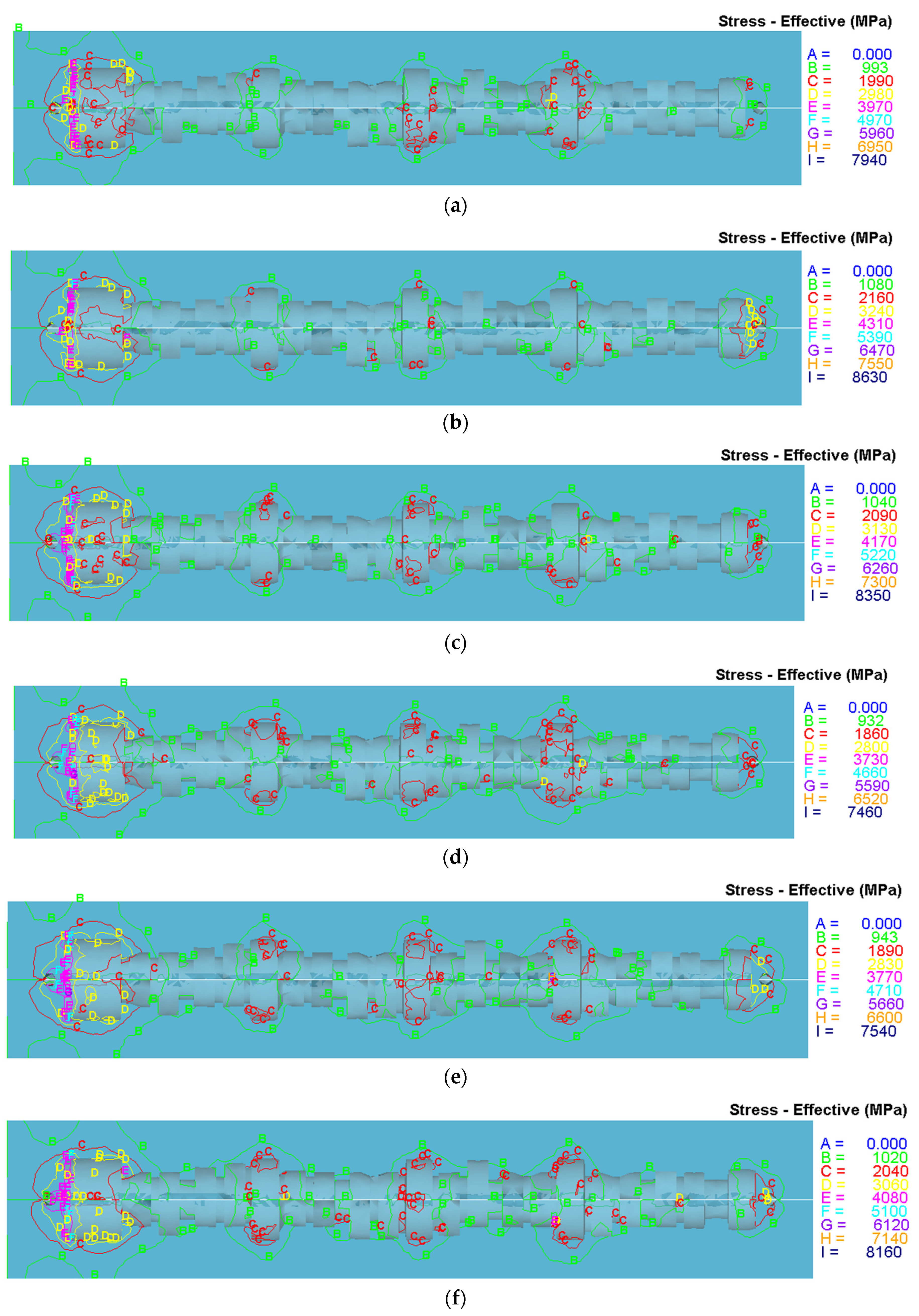
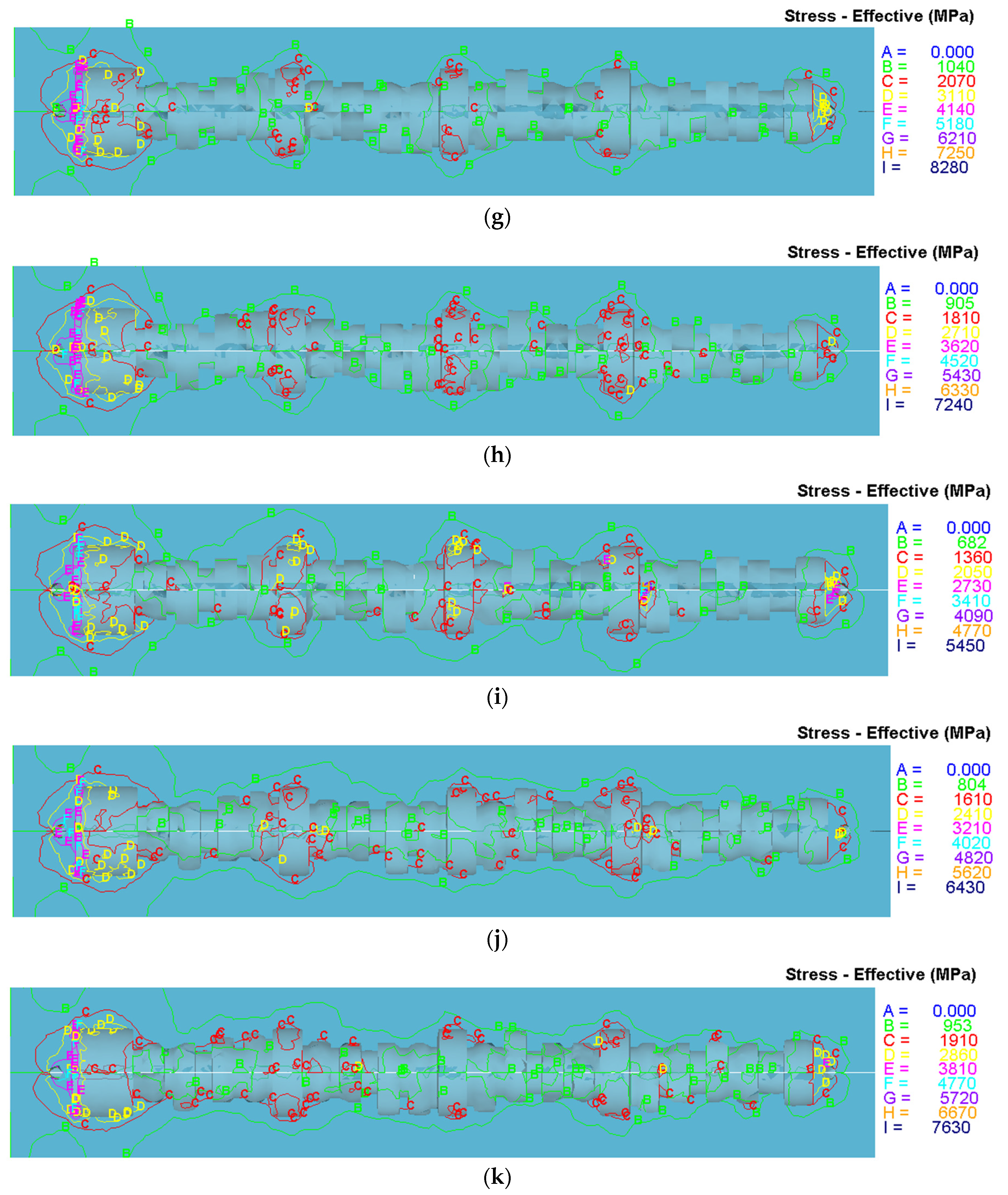
The stress analysis was carried out for all the cases being considered. As expected, the spread of higher values of effective stresses can be seen in the punch and the die as the preform grows in volume through the cases. The concentration of higher values is observed around the ends of the camshaft and the bearing journals which can be attributed to the absence of allowances incorporated in the preform design. The major point of concern remains the stresses induced in the punch and the die due to formation of the cam profiles. An interesting observation is made that the magnitude of the local effective stresses relating to the formation of the cam profiles remain well within the allowable limits of the die material and hence the forge loads may be considered safe for the cold working process. The increase in effective die stresses beyond the permissible limits of the die material leads to plastic deformation of the dies thus affects dimensional conformity of the dies through the process and hence the forged component deviates from the requirements. A reference for effective stresses in the punch and the die can be made in the Figure 9. It must be noted that majority of stress levels are found within 4970 MPa (level F in Figure 9). The higher stress levels such as G, H, I as indicated in Figure 9 are existing at very minute points thus they are not properly visible. For instance, an enlarged Figure 9 would show a small spot of G overlapped by stress level E, at the left end in cases 4 and 5.

4. Conclusions

This study presents the finite element analysis of cold forging process of a V8 engine camshaft. The simulations were carried out on Deform 3D with varying geometry of the preform for the camshaft under study, with AISI 8620 and AISI H-26 as workpiece and die materials respectively. A series of simulations were evaluated for stepped incremental values of cam radius in the preform, for under filling and flash generation. The study provided useful results to obtain optimal preform geometry. 10 cases were studied with an objective to find most suitable scenario. The results indicated that the geometry of the preform corresponding to Case VI may be chosen as the most preferred preform geometry with respect to under filling, flash and die stresses that had the percentage area deviation of 0.32. Future exploration of this subject may include similar analysis incorporating allowances for machining which may also affect die stresses in a positive way. Similar analysis with different pair of materials for punch/die life study and experimental validation could be carried out.

Author Contributions

A.N.S., H.M.T.K., and M.F.A.: Concept design, Experimentation, I.A.B., A.A. (Ali Algahtani), S.K. and T.M.Y.K.: Analysis, Manuscript preparation, review, revision and fund acquisition, A.B.A. and A.A. (Abdulgaphur Athani): Data Collection.

Funding

This research was funded by King Khalid University, under the grant number R.G.P. 2/11/39.

Acknowledgments

The authors extend their appreciation to the Deanship of Scientific Research at King Khalid University for funding this work through research groups program under grant number (R.G.P. 2/11/39).

Conflicts of Interest

The authors declare no conflict of interest.

References

  1. Ishinaga, N. An advanced press design for cold forging. J. Mater. Process. Technol. 1997, 71, 100–104. [Google Scholar] [CrossRef]
  2. Yanagimoto, J.; Sugiyama, S.Y.; Anagida, A.; Iwamura, N.; Ishizuka, M. Control of ultrafine microstructure by single-pass heavy deformation and cold forging of metal. J. Mater. Process. Technol. 2009, 209, 679–685. [Google Scholar] [CrossRef]
  3. Zhang, X.; Peng, Y.; Ruan, X. A web based cold forging process generation system. J. Mater. Process. Technol. 2004, 145, 1–6. [Google Scholar] [CrossRef]
  4. Kim, S.-Y.; Kubota, S.; Yamanaka, M. Application of CAE in cold forging and heat treatment processes for manufacturing of precision helical gear part. J. Mater. Process. Technol. 2008, 201, 25–31. [Google Scholar] [CrossRef]
  5. Deng, X.; Hua, L.; Han, X.; Song, Y. Numerical and experimental investigation of cold rotary forging of a 20CrMnTi alloy spur bevel gear. Mater. Des. 2011, 32, 1376–1389. [Google Scholar] [CrossRef]
  6. Ku, T.-W.A. A Study on Two-Stage Cold Forging for a Drive Shaft with Internal Spline and Spur Gear Geometries. Metals 2018, 8, 953. [Google Scholar] [CrossRef]
  7. Huang, H.-S.; Hsia, S.-Y. New design of process for cold forging to improve multi-stage gas fitting. Adv. Mech. Eng. 2016, 8, 1–12. [Google Scholar] [CrossRef]
  8. Samołyk, G.; Winiarski, G. Analysis of single-operation cold forging of a hollow ball from a tubular billet. Int. J. Adv. Manuf. Technol. 2019, 103, 3045–3056. [Google Scholar] [CrossRef] [Green Version]
  9. Samad, Z.; Abdullah, A.B.; Khaleed, H.M.T.; Abu-Bakar, M.H.; Arshad, M.R. A novel manufacturing method of propeller for autonomous underwatwer vehicle (auv) using cold forging. Indian J. Geo-Mar. Sci. 2012, 41, 242–248. [Google Scholar]
  10. Abdullah, A.B.; Sapuan, S.M.; Samad, Z.; Khaleed, H.M.T.; Aziz, N.A. Manufacturing of AA6061 propeller for AUV application using cold forging process. Sci. Res. Essays 2012, 7, 170–176. [Google Scholar]
  11. Khaleed, H.M.T.; Samad, Z.; Othman, A.R.; Mujeebu, M.A.; Badarudin, A.; Abdullah, A.B.; Ab-Kadir, A.R.; Badruddin, I.A.; Ahmed, N.J.S. Computer-Aided FE Simulation for Flashless Cold Forging of Connecting Rod without Underfilling. Arab. J. Sci. Eng. 2011, 36, 855–865. [Google Scholar] [CrossRef]
  12. Rathore, S.S.; Salve, M.M.; Dabhade, V.V. Dabhade, Effect of molybdenum addition on the mechanical properties of sinter-forged Fe-Cu-C alloys. J. Alloys Compd. 2015, 649, 988–995. [Google Scholar] [CrossRef]
  13. Kim, Y.S.; Son, H.S.; Kim, C.I. Rigid-plastic finite element simulation for process design of impeller hub forming. J. Mater. Process. Technol. 2003, 143–144, 729–734. [Google Scholar] [CrossRef]
  14. Kim, D.J.; Kim, B.M. Application of neural network and FEM for metal forming processes. Int. J. Mach. Tools Manuf. 2000, 40, 911–925. [Google Scholar] [CrossRef]
  15. Khaleed, H.M.T.; Samad, Z.; Othman, A.R.; Mujeebu, M.A.; Abdullah, A.B.; Zihad, M.M. Work-piece optimization and thermal analysis for flash-less cold forging of AUV propeller hubs—FEM simulation and experiment. J. Manuf. Process. 2011, 13, 41–49. [Google Scholar] [CrossRef]
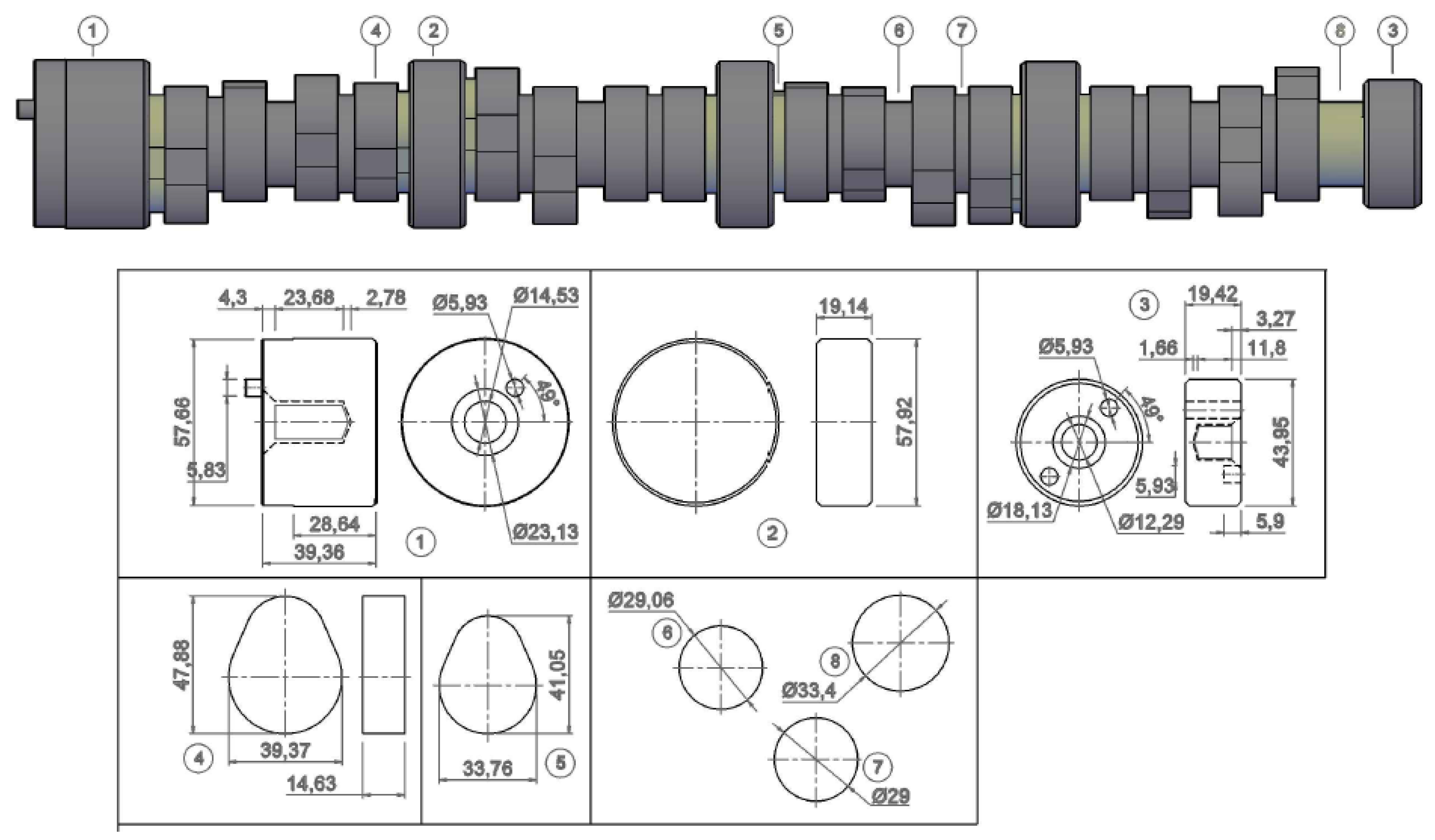
Figure 1. Camshaft geometry.
Mathematics 07 01026 g001
Figure 2. Flow chart emulating the basic workflow.
Mathematics 07 01026 g002
Figure 3. Radius of the base circle of Cams in the Cam-shaft.
Mathematics 07 01026 g003
Figure 4. Radius of the base circle of Cams in the Preform.
Mathematics 07 01026 g004
Figure 5. Flash Gutter in Dies.
Mathematics 07 01026 g005
Figure 6. Gradual Improvement of Profile of CAM.
Mathematics 07 01026 g006
Figure 7. Cavity/undefiled volume in different cases studied. (a) Case I; (b) Case II; (c) Case III; (d) Case IV; (e) Case V; (f) Case VI; (g) Case VII; (h) Case VIII; (i) Case IX; (j) Case X.
Mathematics 07 01026 g007aMathematics 07 01026 g007b
Figure 8. Flash produced in each case. (a) Case I; (b) Case II; (c) Case III; (d) Case IV; (e) Case V; (f) Case VI; (g) Case VII; (h) Case VIII; (i) Case IX; (j) Case X.
Mathematics 07 01026 g008aMathematics 07 01026 g008bMathematics 07 01026 g008cMathematics 07 01026 g008d
Figure 9. Effective stresses in the punch and die. (a) Case I; (b) Case II; (c) Case II; (d) Case IV; (e) Case V; (f) Case VI; (g) Case VII; (h) Case VII; (i) Case IX; (j) Case X; (k) Case VI (filleted Dies).
Mathematics 07 01026 g009aMathematics 07 01026 g009b
Table 1. Specification of the Camshaft.
Intake/Exhaust Durations:
  • 268/271 @0.006” Lift
  • 206/211 @0.050” Lift
Maximum lift0.340”/0.330”
Lobe Separation Angle117.5°
Intake Centre Line of Camshaft121.5°
Table 2. Details of discretization.
CaseNo. of Elements
Pre-FormPunchDie
V1032665019051441
Table 3. Specifications of Die, Punch and Preform.
PropertyPreformDie/Punch
CategorySteelSteel
ClassAlloy SteelTool Steel
Common NameNickel-chromium-molybdenum steelTungsten Hot Work Steel
Density (×1000 kg/m3)7.7–8.038.67
Poisson’s Ratio0.27–0.300.27–0.30
Elastic Modulus (GPa)190–210190–210
Tensile Strength (Mpa)536.4650–880
Yield Strength (Mpa)385.4350–550
Hardness (HB)149545–560
Table 4. Volumetric Analysis of Preform Geometry.
CasesRC (mm)RJ (mm)Preform Vol. (mm3)Product Vol. (mm3) [A]Target Vol.(mm3) [B]Under-Filling (% of Target Volume)Flash (% of Preform Volume)
I21.33529721,592691,113719,2233.914.22
II2229731,953697,838719,2232.974.66
III22.529747,960702,868719,2232.276.03
IV2329768,428706,056719,2231.838.12
V23.529785,252701,589719,2232.4510.65
VI2429802,439706,727719,2231.7411.93
VII24.529819,989704,722719,2232.0214.06
VIII2529838,737705,113719,2231.9615.93
IX25.529857,012708,054719,2231.5517.38
X2629877,166705,342719,2231.9319.58
Table 5. Percentage of Deviation from Targeted Area.
CaseTarget Area mm2Recorded Area mm2Percentage Deviation
I1433.771346.366.10
II1372.034.31
III1378.483.86
IV1417.981.10
V1429.160.32
VI1430.320.24
VII1430.50.23
VIII1428.660.36
IX1429.160.32
X1424.850.62