1. Introduction
Transforming a natural-language task description into an executable industrial grasp requires a consistent mapping from semantic constraints to measurable scene evidence. The instruction must first be parsed into a structured representation of the action, target category, defect status, spatial relation, and placement region. Candidate workpieces must then be separated in the point cloud and evaluated for local geometric irregularities. Finally, the grounded target must be converted into a collision-free grasp pose. The central challenge is to ground a constraint such as “the defective cube on the left” to one physical instance while retaining enough geometric evidence to avoid unstable contact regions.
Application-specific AI methods provide complementary examples of constraint-aware design in cyber-physical systems [
1,
2,
3,
4,
5]. Personalized federated learning has been used for intrusion detection under heterogeneous sensor-network data, multi-task learning has supported real-time water-level prediction, deep reinforcement learning has been applied to latency–energy-aware computation offloading in smart healthcare networks, edge computing and AI have been examined jointly in autonomous transportation systems, and the integration of data science with the intelligent Internet of Things has been surveyed in terms of current challenges and future directions. Although these studies address different tasks, they illustrate the broader value of separating domain-specific sensing, inference, and decision modules instead of relying on an undifferentiated end-to-end process.
Existing methods address only fragments of this pipeline. Point-cloud perception methods [
6,
7,
8,
9,
10] provide scene understanding but typically do not handle language-conditioned target selection. Language-guided robot planning methods [
11,
12,
13,
14,
15,
16,
17,
18,
19] improve action generation or task-level reasoning but usually do not model local geometric defects in industrial point-cloud scenes. Grasping methods [
20,
21,
22,
23,
24] generate 6-DoF grasp poses but generally assume the target object is already given and do not address task-conditioned selection among multiple workpieces with defect constraints.
This paper presents a geometric point-cloud perception and defect-aware grasping framework that leverages 3D geometric cues to detect surface defects and guide robotic manipulation. The proposed method parses language instructions, detects workpiece surface defects through multi-cue geometric analysis, selects the correct defective target via defect-aware target grounding, and generates stable grasp poses that avoid contact with high defect-response regions.
Although the proposed framework accepts natural-language instructions and generates executable grasp poses, it is not intended as a general-purpose vision–language–action (VLA) policy. Instead, it provides an interpretable geometric reasoning layer that explicitly measures local surface defects and incorporates this evidence into target grounding and grasp-contact evaluation. The geometric perception and grounding components require no task-specific training on annotated industrial defect or grasping datasets, making it potentially useful for small-batch manufacturing scenarios in which large annotated defect datasets are unavailable.
The core idea is to distinguish defective-object selection from defective-region contact. The language instruction requires selecting the defective workpiece as the manipulation target, whereas the grasp planner should avoid using the defective local region as the contact area because dents and scratches may reduce contact stability. The defect response map serves two purposes: target-level defect consistency evaluation and contact-level stability reasoning.
The main contributions of this work are threefold:
We formulate defect perception as an interpretable multi-scale geometric evidence aggregation problem, producing point-level response maps and instance-level defect scores without task-specific training on annotated industrial defect data. The multi-cue fusion of curvature, normal consistency, plane fitting residual, concavity, and density anomaly provides traceable geometric evidence for each decision.
We introduce defect-constrained target grounding that binds symbolic attributes parsed from natural-language instructions to measurable 3D geometric evidence, enabling selection among multiple visually or geometrically similar workpieces based on explicit defect-aware criteria.
We propose a dual-role defect reasoning mechanism in which the same response map supports defective-object selection at the instance level and suppresses unreliable defective contact regions during grasp candidate ranking, thereby separating target-level defect selection from contact-level stability reasoning.
3. Method
Scope and Positioning. This work is a prototype feasibility study rather than a general-purpose VLA model or a large-scale robotic manipulation system. The validated setting is a structured industrial tabletop scene in which simple workpieces (cone, cube, cylinder, and rectangular prism) are spatially separated on a flat support surface and observed by a fixed RGB-D camera. The proposed framework uses 3D geometric analysis for defect-aware target grounding and grasp evaluation without task-specific training of the geometric modules. Claims of effectiveness are therefore restricted to this controlled setting.
3.1. Problem Formulation
Given a natural language instruction , an RGB-D observation , and a 3D point cloud , the goal is to select a target workpiece instance and generate a stable grasp pose for pick-and-place manipulation. The central challenge is a three-stage mapping: from language to structured grasp specification, from specification to target instance, and from target instance to executable grasp parameters. We address three core sub-problems: parsing natural language into structured task representations, detecting workpiece surface defects from local geometric regularity violations, and grounding the task specification to the correct defective target under joint semantic, geometric, and grasp-specific constraints.
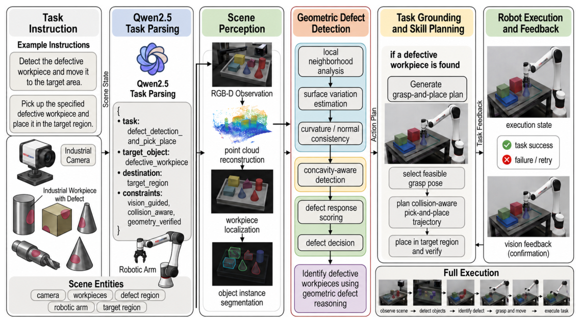
Figure 1 shows the detailed pipeline from task parsing to defect-aware target grounding and grasp pose generation. The system first parses the language instruction into a structured grasp specification and then extracts geometric features from the point cloud to detect defective workpieces, grounds the target under multi-criteria evaluation, and finally generates executable parallel-gripper grasp poses.
3.2. Task Parsing and Structured Grasp Specification
A natural language instruction
is parsed by a large language model into a structured grasp specification:
where
a is the action type (e.g., pick-and-place),
c is the target object category (e.g., cube, cylinder, cone, or rectangular prism),
d is the defect constraint (e.g., defective or non-defective),
is the target object location description (e.g., left, center, or right),
is the placement region (e.g., bin, left-side, or right-side), and
is the execution constraints (e.g., stable grasp; avoid collision).
The LLM is used only as a task parser rather than as a direct robot controller. Its output is converted into a structured task specification and verified by rule-based field checking before being passed to the geometric grounding module.
For example, the instruction “Pick up the defective cylinder on the left and place it in the bin” is parsed into the following:
This structured representation bridges natural language ambiguity and geometric reasoning by extracting task-relevant attributes that guide downstream perception and planning.
We use Qwen2.5-7B-Instruct as the language model for task parsing. The model is deployed locally via vLLM with temperature set to 0.0 for deterministic parsing. The system prompt specifies the JSON schema for the structured task representation, and field validation is performed by rule-based checking before downstream processing.
Table 2 reports the per-field parsing accuracy on the 60 language commands.
3.3. Point-Cloud Scene Representation and Instance Grounding
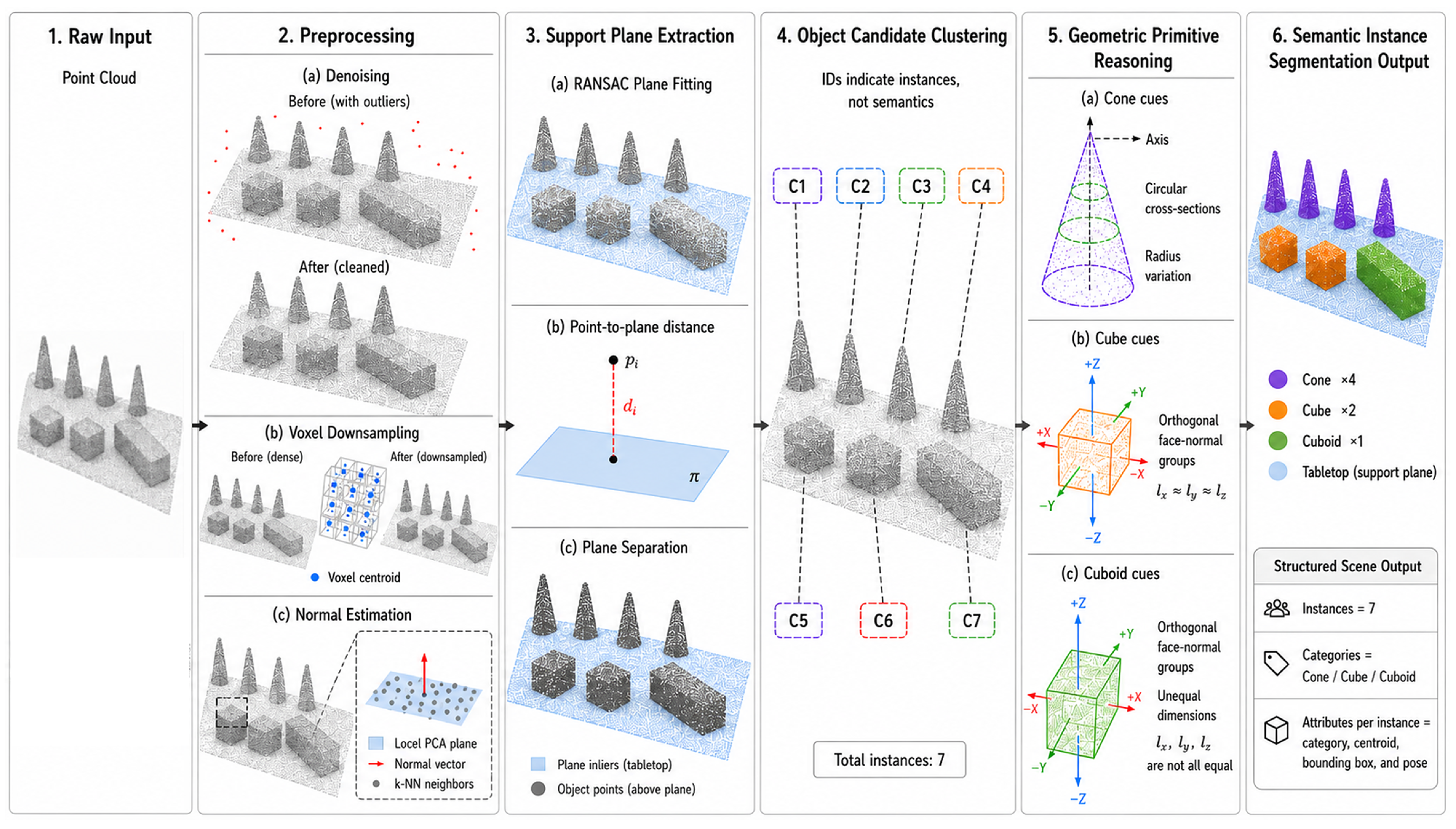
The proposed system directly performs 3D point-cloud instance segmentation to extract individual workpiece instances from the scene. The scene is represented as two layers. The object instance layer
is obtained through 3D point-cloud preprocessing: voxel downsampling, support-plane removal, Euclidean clustering, and geometry-based instance segmentation. The RGB image is used only as auxiliary observation or for visualization, while target grounding and defect reasoning are conducted in the 3D point-cloud domain. The geometric entity layer
is constructed from
and spans types such as
hole-like-defect,
depression,
planar-face,
edge, and
object-body. Entity generation is based on local covariance analysis, providing the geometric descriptors that underpin both defect reasoning and grasp pose generation:
The eigenvalues
are computed by eigendecomposition of
, and the geometric feature vector is as follows:
where
is the curvature anomaly,
is the normal consistency,
is the plane fitting residual,
is the concavity response, and
is the density anomaly. The planarity and linearity descriptors (
and
) are derived from the same eigenvalue ratios and are used exclusively for candidate grasp-region generation, not for defect scoring. Candidate grasp regions are generated by thresholding and region growing over planarity and linearity responses, followed by task-dependent geometric verification.
Table 3 consolidates the symbols used for geometric defect reasoning and grasp generation.
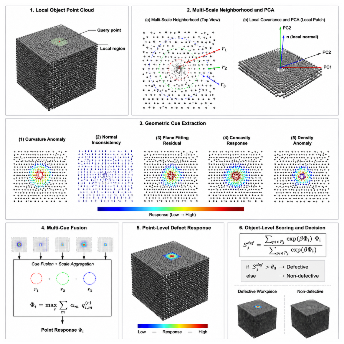
Figure 2 illustrates the local geometric defect detection process. Multi-scale neighborhoods are constructed around each query point, followed by local PCA-based reference frame estimation, geometric cue extraction, multi-cue fusion, point-level defect response generation, and instance-level defect scoring.
3.4. Multi-Cue Geometric Defect Detection
Industrial surface defects are formulated as violations of local geometric regularity. As shown in
Figure 2, for each point
of object
, five local geometric response signals are computed across multiple neighborhood radii
and combined into a unified defect score.
Definition of geometric cues. The five geometric cues are computed from local covariance analysis as follows:
Curvature anomaly : the local sphericity derived from the normalized eigenvalue ratio , indicating local surface curvature. Higher values suggest curved or non-planar regions.
Normal consistency : computed as the average dot product between the query-point normal and neighbor point normals within radius r. To ensure consistent normal orientation, the query-point normal is first oriented toward the camera center (which lies at a known fixed position above the scene), and all neighbor normals are then re-oriented to have a positive dot product with the query-point normal before averaging. Lower values indicate inconsistent normals typical of scratches, cracks, or defect boundaries.
The normal-consistency cue is invariant to a simultaneous sign reversal of the query and neighboring normals because it depends on their dot products. The signed concavity cue is not sign invariant; consequently, the camera-facing convention is applied before signed residuals are computed. This convention is reliable in the fixed overhead setup but has not been validated for moving viewpoints, open surfaces viewed from both sides, or severe occlusion.
Plane fitting residual : the mean orthogonal distance from neighbor points to the locally fitted plane, capturing local surface smoothness.
Concavity response : computed from signed residuals , where . This detects local concavities such as dents, holes, and depressions.
Density anomaly : the deviation of local point density from the median density within the object, serving as an auxiliary cue for detecting sparse or dense surface regions. Note that point-cloud density variation may also arise from sensor sampling, viewing angle, or edge effects, so this cue should be interpreted in conjunction with other geometric cues.
All cue values are normalized to within each object instance using robust min–max normalization based on the 5th and 95th percentiles.
Point-level defect response. The point-level defect response aggregates geometric cues across spatial scales:
The cue weights
are set uniformly (
) by default. Uniform weights are not assumed to be optimal; they are adopted to avoid fitting defect-specific weights on the limited validation set and to preserve a defect-type-independent formulation. The multi-scale max aggregation naturally selects the most discriminative scale for each point. The temperature parameter
and defect threshold
are selected on a held-out validation set consisting of 4 instances per geometry type (2 defective; 2 non-defective), stratified by defect status. This validation set is strictly separated from the test set, and parameters are fixed before evaluating on the test set to avoid data leakage.
Instance-level defect scoring. The instance-level defect score aggregates point-level responses over the object point set
:
The softmax-weighted mean emphasizes high-response regions. The dominant response pattern provides an interpretable attribution of the prevailing geometric abnormality. An object
is classified as defective (
) if its defect score exceeds the threshold
.
As shown in
Figure 3, the input scene point cloud is first preprocessed and segmented into multiple workpiece instances. For each instance, the local geometric defect detector is applied to estimate the defect response and confidence score. The detected defect information is then combined with the structured task specification to determine the target object.
3.5. Defect-Constrained Target Grounding
From the full object instance set
, a task-relevant subset
is selected based on the category constraint in
. Each candidate is scored by multiple factors and ranked by a grouped multiplicative objective:
The multiplicative formulation has two important properties. First, it penalizes candidates that fail to satisfy any critical task constraint: if any score term is near zero, the overall score becomes near zero regardless of other terms. Second, in implementation, each score term is clipped to a small positive range to avoid numerical instability.
Here, each scoring term is defined as follows:
Category similarity : computed based on the geometric primitive matching between the detected shape of and the target category c. For each candidate, we extract dominant geometric primitives (planar, cylindrical, conical, and spherical) from the point cloud and compute a similarity score based on primitive type matching and geometric parameter deviation.
Location satisfaction : the spatial location score is computed by projecting the object centroid onto the horizontal plane and comparing its relative position (left, center, right, front, and back) with the language-specified location . Specifically, , where is the relative distance to the target region, and is the maximum scene extent.
Defect consistency : defined in Equation (
10) below.
Geometric graspability : computed from local planarity and clearance metrics. For a candidate grasp region, evaluates the planarity score (based on eigenvalue ratios) and the minimum clearance distance to neighboring objects or the table surface. Higher planarity and larger clearance yield higher graspability scores.
Reachability : collision-free inverse kinematics reachability is evaluated by attempting IK solutions for the candidate grasp pose. The reachability score is the ratio of successful IK solutions to total attempts, capped at a threshold that ensures collision-free paths.
Safety : the safety score evaluates collision-free grasp execution by checking the minimum distance between the gripper trajectory and obstacles. It is computed as follows:
where
is the minimum clearance during execution, and
is a safety margin threshold.
All scores are normalized to , with 1 indicating perfect satisfaction. The placement region is reserved for the placement planning stage and does not participate in target grounding. The group weights are task-dependent and selected on a validation set.
The defect constraint term
is defined as follows:
This term directly uses the instance-level defect score
computed from the multi-cue geometric defect scoring. If the top-ranked candidate fails to satisfy the grasp feasibility check, the system triggers re-grounding with relaxed constraints.
3.6. Geometry-Guided Grasp Pose Generation
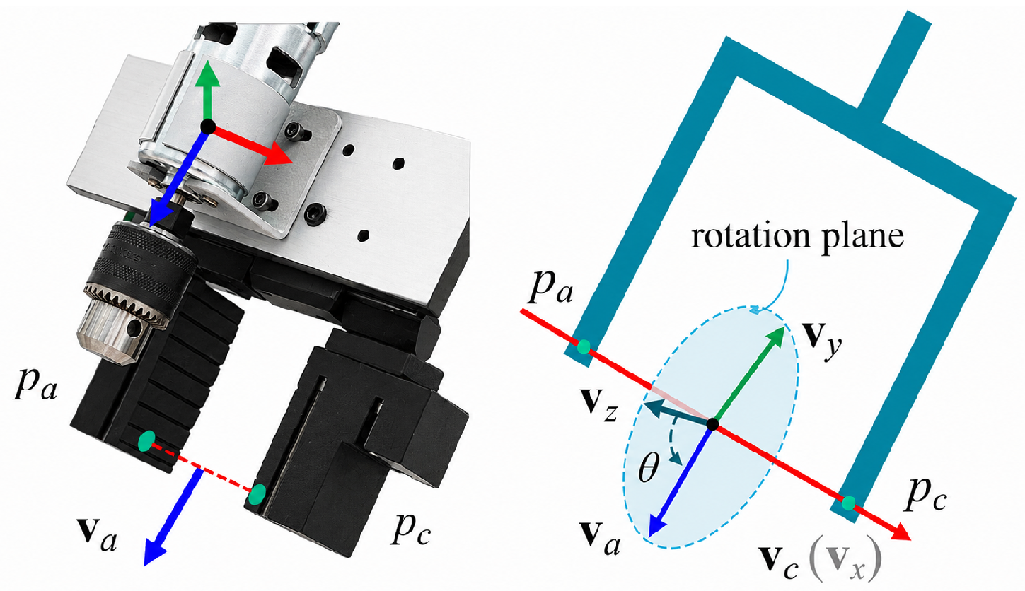
Figure 4 shows the geometric parameterization of the parallel gripper pose. The grasp pose is represented by the grasp center
, the approaching direction
, the closing direction
, and the grasp width
, as defined in the gripper coordinate frame.
The defect-free contact term does not reject the defective workpiece; instead, it penalizes grasp candidates whose contact regions overlap with high defect-response areas.
Given the grounded target
, executable grasp parameters are generated by a geometry-guided parameterizer:
The grasp center is computed as the centroid of the candidate grasp region:
where
is the candidate grasp region point set on
.
The approaching direction is set as the negative of the local surface normal:
The closing direction is selected to maximize grasp stability:
where
and
are the principal directions of the local point cloud, and
measures the grasp width and clearance along direction
.
Although the defect constraint is used to select the target workpiece, the defective region itself is not necessarily suitable for contact. Dents and scratches may cause unstable contact or slippage. Therefore, after the defective target is grounded, the defect response map is reused to suppress grasp candidates whose contact regions overlap with high-response defective areas.
The grasp quality score combines multiple criteria including defect avoidance:
which penalizes grasp candidates whose contact regions contain high defect-response points. The overall quality score is as follows:
where
measures alignment with the surface normal,
measures grasp clearance,
measures pose stability,
measures collision-free safety, and
penalizes grasp candidates whose contact regions overlap with high defect-response areas. The final gripper pose matrix is as follows:
3.7. Execution Feedback and Recovery
The system includes a two-level recovery mechanism that handles execution failures using built-in gripper force feedback and visual tracking. The measured force is read from the built-in force-feedback interface of the gripper. The force threshold is set to 15 N according to the gripper specifications, and the deviation threshold is set to 10 mm based on the visual tracking accuracy. The maximum number of attempts is set to 3.
Level-1 (Re-ranking): If the force reported by the built-in gripper feedback exceeds or the visual tracking deviation exceeds , the system re-ranks remaining grasp candidates by re-evaluating for all and selects the highest-scoring candidate.
Level-2 (Re-targeting): If all grasp candidates fail or no valid candidates remain, the system relaxes the task specification. The re-targeting step preserves the object category and defect-status constraints: only lower-priority spatial preferences or grasp-clearance margins may be relaxed. Specifically, the target may be re-grounded to a different candidate instance of the same category and defect status, or the spatial relation constraint (e.g., left/center location tolerance) may be widened. If no candidate satisfies the original semantic constraints, the system returns a failure signal or requests user confirmation rather than automatically relaxing the defect constraint to any.
If both recovery levels fail after attempts, the system returns a failure signal. This two-level approach handles perception noise and minor geometric deviations efficiently at Level-1, while Level-2 addresses systematic failures that require task-level modifications.
4. Experimental Results
The experimental platform consists of a fixed RGB-D camera (Vizum VZ-AI-1920(2048)-320M3K) and a 6-DoF industrial robotic arm (Hikvision robot) equipped with a parallel gripper. The point cloud is captured at 30 fps with approximately 307,200 points per frame. The camera is mounted at a fixed overhead viewpoint, approximately 0.8 m above the table surface, with a tilt angle of approximately 30 degrees from vertical. Point-cloud preprocessing includes voxel downsampling (grid size 5 mm), support-plane removal (RANSAC with distance threshold 10 mm), and Euclidean clustering (cluster tolerance 8 mm; minimum 200 points per cluster). Four representative workpiece geometries are considered: cone (height 60 mm; base radius 30 mm), cube (50 mm side), cylinder (height 70 mm; radius 25 mm), and rectangular prism (60 mm × 40 mm × 30 mm). The defect types include hole-like depressions (diameter 8–15 mm; depth 2–5 mm) and scratch-like surface anomalies (length 10–30 mm; width 1–3 mm). Defects are created by manual indentation or surface scratching to simulate real industrial surface anomalies.
Experimental assumptions. The current implementation assumes that workpieces are spatially separated by at least 30 mm after support-plane removal to ensure reliable Euclidean clustering and defect scoring. When two workpieces touch or overlap in depth, Euclidean clustering can merge them into one instance, invalidating both the instance-level defect score and the downstream reachability term. The system therefore rejects scenes that violate the separation condition rather than reporting a grasp result. Touching and stacked workpieces have not been experimentally evaluated.
Ground truth annotation. Defect ground truth is established at the instance level by two experienced operators through independent visual inspection under controlled lighting. A workpiece is labeled as defective when both operators agree; disagreements, which occur in fewer than 5% of cases, are resolved by a third senior operator. The first operator outlines the visible defect region, and the second verifies the outline. These region annotations support qualitative inspection only; the quantitative evaluation is restricted to instance-level defect classification because point-level localization accuracy is not evaluated. Representative defect dimensions are measured with a digital caliper with 0.01 mm resolution.
Experimental Protocol. Experiments on the prototype industrial workpiece setup evaluate three aspects: geometric defect detection, defect-aware target grounding, and robotic grasp execution. All trials are conducted under normal indoor lighting conditions (approximately 300–500 lux).
The physical dataset contains 80 workpiece instances in total. A held-out subset of 16 instances (four per geometry) is used only for parameter selection, and the remaining 64 instances form the defect-detection evaluation pool.
The defect F1-score is computed at the instance level by comparing detected defect status with manually annotated ground truth. For target grounding, 60 language commands cover combinations of object category, defect constraint, and spatial location. The commands are categorized into four types: category-only (e.g., “pick the cube”), category plus location (e.g., “pick the cube on the left”), category plus defect (e.g., “pick the defective cube”), and category plus defect plus location (e.g., “pick the defective cylinder on the left”). Grounding accuracy is measured as Top-1 (correct target ranked first) and Top-3 (correct target in top three). For grasp execution, 120 trials are conducted across all workpiece types; each trial includes approach, grasp, lift, transport, and place phases. A trial is successful only if all phases complete without collision or slip. Grasp error and placement error are measured as Euclidean distances between planned and actual positions, estimated from visual tracking. All reported ± values denote the standard deviation computed across five repeated experimental runs with randomized workpiece placement.
Baseline definitions. The evaluated baselines include both ablated variants of the proposed method and classical geometric anomaly detection methods. Curvature Threshold: a classical approach that classifies a point as defective if its curvature anomaly exceeds a threshold tuned on the validation set. Normal Variation: classifies based on the variance of local point normals within the neighborhood. Plane Fitting Residual: classifies based on the mean orthogonal distance to a locally fitted plane. Two-dimensional Mask Projection: a weak baseline that first obtains 2D object masks from RGB images using simple color-based segmentation and then projects the masks into the point cloud for target association. It does not directly perform 3D instance segmentation or local geometric defect scoring. Three-dimensional Instance Segmentation Only: point-cloud Euclidean clustering is used for object identification, but defect labels are inferred from simple instance-level geometric statistics (e.g., bounding box irregularity) without the proposed multi-cue defect scoring. Language-only Grounding: uses the parsed symbolic attributes and coarse spatial relations to rank candidate instances, but it does not use point-cloud defect evidence or geometric grasp-quality scores. Single-cue Geometry: only a single geometric feature (e.g., curvature anomaly alone) is used for defect detection without multi-cue fusion. Multi-cue Mean Fusion: uses the proposed five geometric cues but performs simple point-level averaging without multi-scale aggregation or softmax-weighted instance-level scoring; the defect score is thresholded directly on the averaged point-level response. Grounding w/o Language: uses multi-cue defect scoring for target selection but without language-conditioned target grounding; targets are selected based on defect score alone. Grasp w/o Defect-Free Contact: uses the same defect-aware target grounding as the full method but removes the defect-free contact term () during grasp candidate ranking. w/o Recovery: uses the proposed full framework but disables the feedback-based re-ranking or re-targeting mechanism.
The validation, evaluation, command, and execution partitions are summarized in
Table 4.
PointNet++ baseline protocol. The PointNet++ baseline [
7] is evaluated through stratified five-fold cross-validation on the 64-instance evaluation pool. In each fold, approximately 51 instances are used for training and 13 for testing. Within each outer training fold, 10% of the training instances are reserved as an inner validation subset for early stopping; the outer test fold is not used for model selection. Each instance receives one out-of-fold prediction, and the pooled predictions over the five held-out folds are used to compute the final F1-score. Class weighting is applied to handle slight class imbalance. The model uses 1024 points per object and is trained for up to 200 epochs with the Adam optimizer, an initial learning rate of
with cosine decay, dropout of 0.5, and early stopping on the inner-validation loss. The random seed is fixed to 42. The reported PointNet++ deviation reflects variation across the five held-out folds, whereas deviations for the geometric methods reflect five repeated runs with randomized workpiece placement; these deviations therefore quantify different sources of variability and are not interpreted as directly equivalent uncertainty estimates.
The final values, validation ranges, and selection criteria for the principal hyperparameters are listed in
Table 5.
Sensitivity analysis. The defect threshold and temperature have distinct roles. Increasing improves precision but reduces recall, whereas controls how strongly high-response points influence the instance score. Equal cue weights are retained to avoid fitting defect-specific weights on only 16 validation instances. The present study reports a quantitative sweep only for ; it does not provide sufficient evidence to claim robustness to all combinations of , group weights, or grasp-quality weights. Those parameters are therefore reported for reproducibility, and broader sensitivity analysis remains necessary before generalizing beyond the controlled setup.
Post hoc sensitivity analysis. Table 6 presents a post hoc sensitivity analysis of
on the 64-instance evaluation pool. These results were not used for parameter selection;
had already been fixed using the independent 16-instance validation set before evaluation on the 64-instance pool. The table shows the local variation of precision and recall around the preselected threshold and should not be interpreted as test-set tuning or as evidence that the threshold is optimal on unseen data.
4.1. Defect Detection Evaluation
The defect detection results on the evaluated workpiece samples are reported in
Table 7.
The proposed method achieves an average F1-score of 0.89 ± 0.02 among the evaluated baselines. PointNet++ [
7] achieves 0.83 ± 0.03 using five-fold out-of-fold evaluation on the 64-instance evaluation pool, with approximately 51 training instances and 13 test instances per fold. In contrast, the proposed geometric method does not require task-specific model training. The comparison is intended to contextualize the training-free formulation rather than establish broad superiority over learning-based defect detectors. Performance is strongest on planar cube surfaces and weaker for scratch-like defects on rectangular prisms, indicating sensitivity to point-cloud resolution and surface geometry.
4.2. Defect-Aware Target Grounding Evaluation
Target grounding accuracy is reported in
Table 8.
The proposed method achieves the highest Top-1 grounding accuracy of 0.89 ± 0.02 (overall micro-average on 60 commands) and Top-3 accuracy of 0.95 ± 0.02. The multiplicative formulation in Equation (
7) penalizes candidates that fail on any single criterion. The defect-aware tasks (e.g., “pick the defective cylinder”) show the largest improvement because the defect consistency score acts as a hard filter for target selection. Analysis of failure cases reveals that most failures occur in category-only instructions where the robot must select among multiple instances of the same category without location or defect constraints; in such cases, the ambiguity in language grounding leads to incorrect target selection.
The headline Top-1 accuracy is computed as a micro-average over all 60 commands in each run and is not obtained by averaging rounded category-level values. To avoid an unverifiable reconstruction from rounded subgroup values, the category-specific numbers are not used as headline evidence. Qualitatively, errors occur more often for cylinders and rectangular prisms because their geometry produces several grasp candidates with similar scores.
Table 9 reports the grounding accuracy breakdown by command type. The results demonstrate that the full defect-aware grounding is critical for commands that specify defect constraints; without defect scoring, the accuracy drops significantly from 0.91 to 0.72 for category-plus-defect commands.
4.3. Grasp Execution Evaluation
Grasp execution success rates and parameter errors are reported in
Table 10.
The proposed method achieves the highest overall success rate of 84.0% ± 3.0%. The most significant improvement comes from the defect-aware grounding and the recovery mechanism: without defect awareness, the system frequently attempts to grasp on defective regions that lead to grasp failure; without the recovery mechanism, any grasp misalignment or execution deviation triggers an unrecoverable failure. The execution time is decomposed as follows: task parsing (0.3 s), point-cloud preprocessing (0.6 s), defect detection (0.9 s), target grounding (0.2 s), grasp planning (0.6 s), and robotic execution (1.5 s).
Failure analysis accounts for all observed failures: grasp slippage on defective contact regions (38%), collision with neighboring objects (25%), localization error due to point-cloud noise (22%), and other failures including inverse-kinematics and gripper-actuation errors (15%).
4.4. Ablation Study
Ablation results are reported in
Table 11.
Removing multi-cue fusion reduces both grounding and grasp performance because single cues are less discriminative for defect detection. The spatial-relation ablation affects target grounding and downstream grasp planning but not defect scoring. The defect-free contact term operates only during grasp ranking; therefore, its removal does not change defect F1 or initial grounding accuracy, and the corresponding cells are marked “—” rather than repeating the full-method values. Likewise, removing recovery affects execution only and leaves the initial perception and grounding outputs unchanged.
4.5. Statistical Significance Analysis
Pairwise tests are conducted on matched per-instance, per-command, or per-trial outcomes. McNemar’s test is used for binary defect-classification correctness on 64 evaluation instances, grounding correctness on 60 commands, and grasp success on 120 trials. The reported F1 or accuracy difference is summarized separately from the McNemar test, which operates on discordant correctness pairs. The paired Wilcoxon signed-rank test is used for grasp and placement errors only on matched trials for which both methods produce valid measurements; failed trials remain in the success-rate comparison. Holm–Bonferroni correction controls the family-wise error rate within each metric family, and 95% confidence intervals are computed by paired bootstrap resampling with 10,000 resamples. These tests rely on the paired outcome records; aggregate table values alone are insufficient to reconstruct the contingency tables.
Table 12 reports descriptive metric differences alongside paired tests after Holm–Bonferroni correction. For defect detection, the descriptive F1 gaps are +0.06 relative to PointNet++ and +0.09 relative to Multi-cue Mean Fusion; the corresponding paired correctness comparisons yield adjusted
and
, respectively. For grasp execution, the defect-free contact term is associated with a +12% success difference (adjusted
), and the recovery mechanism with a +9% difference (adjusted
). These inferences remain conditional on the matched outcome records described above; the aggregate values in this manuscript are not sufficient to independently recompute the tests.
4.6. Qualitative Robotic Execution Demonstration
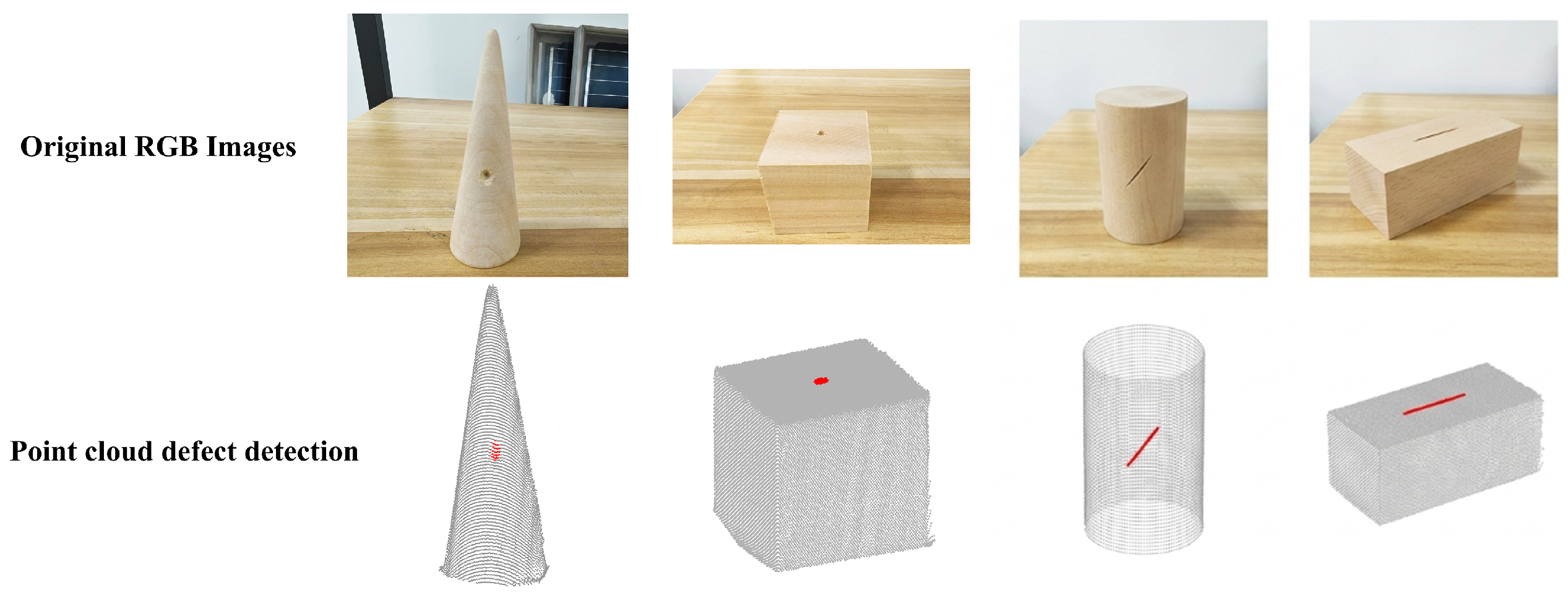
Figure 5 shows the experimental workpieces and point-cloud defect examples. The evaluated objects include a cone, cube, cylinder, and rectangular prism with representative hole-type and scratch-type defects. Red markers indicate the defect locations used for geometric defect evaluation.
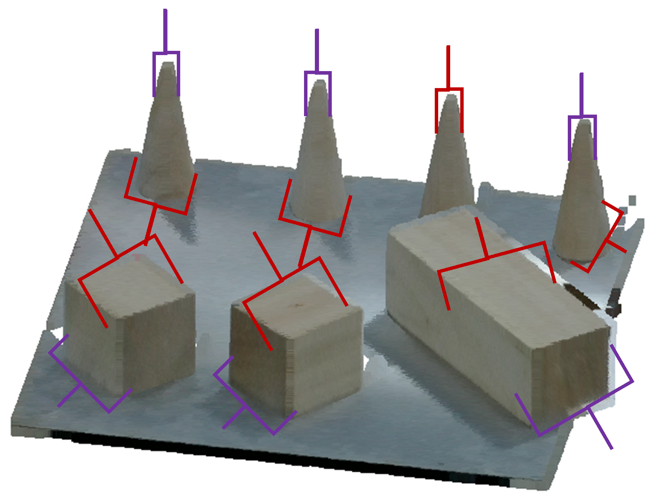
Figure 6 shows the reconstructed scene, manually marked defect locations, and generated grasp orientations. The current composite does not contain a calibrated point-level defect-response heat map or a quantitative comparison with region-level ground truth. It is therefore used only to illustrate scene interpretation and grasp generation. Quantitative claims in this study remain restricted to instance-level defect classification, target grounding, and grasp execution.
The proposed method identifies individual workpieces from the point cloud, detects local defective regions through geometric defect scoring, and generates corresponding grasping directions for robotic manipulation.
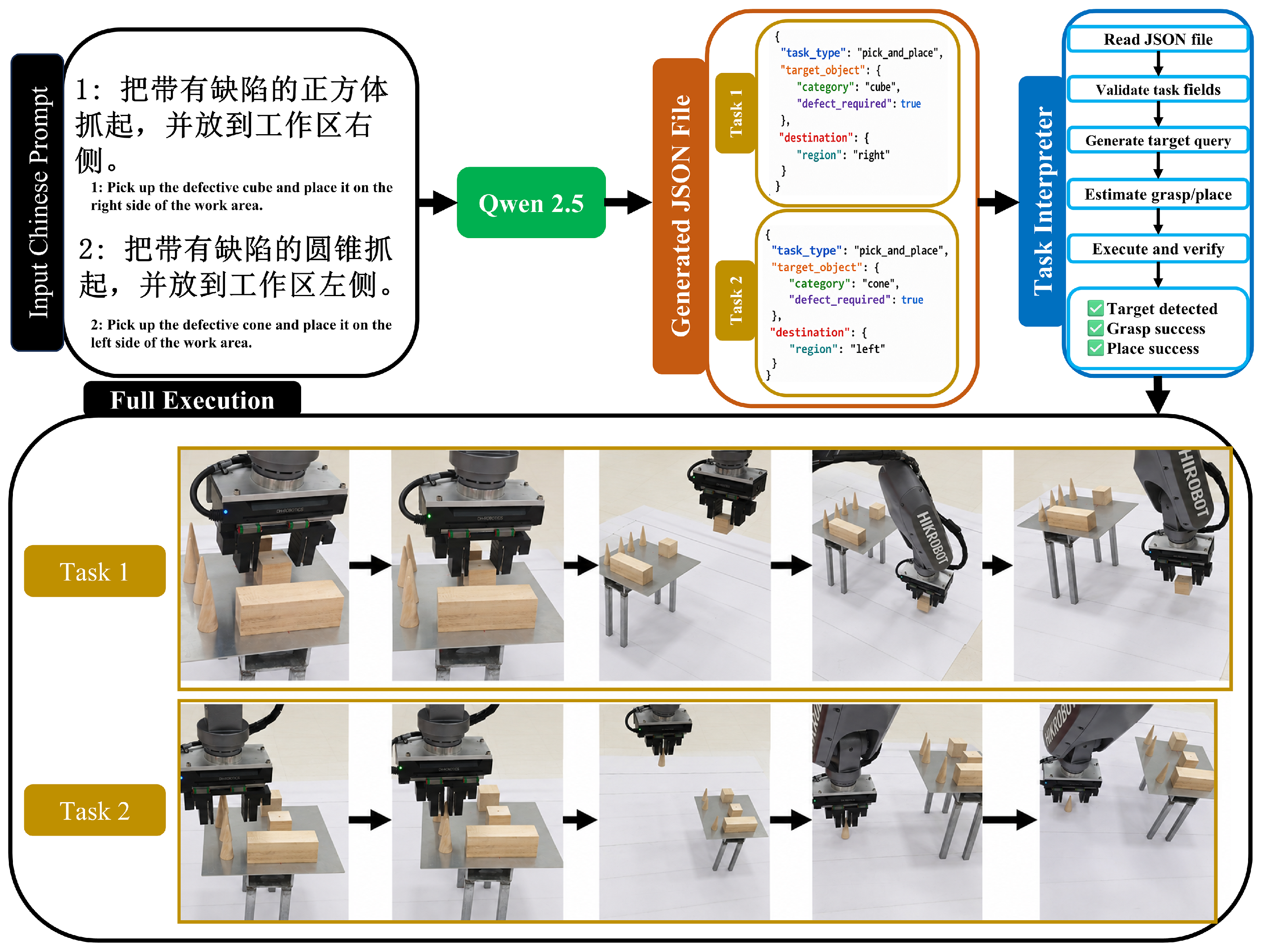
Figure 7 demonstrates the complete language-to-action execution process. The original user commands are given in Chinese, and their English translations are shown in the figure for readability. The language instruction is first parsed by the language model into a structured task representation. The perception module then grounds the target object according to the defect-aware scene analysis. Finally, the robot executes the corresponding grasping and placing actions.
5. Discussion
The experiments evaluate the feasibility of the proposed framework in a controlled prototype setting. The results support discussion of the geometric formulation, target-grounding mechanism, and recovery behavior within that setting, but they do not establish general performance in cluttered industrial scenes.
On the geometric-defect formulation. The cue contributions in Equation (
5) provide a qualitative indication of the geometric abnormality that drives a response. A concavity-dominant or normal-inconsistency-dominant response may help interpret a detected region, but this study does not evaluate defect-type classification. Cue dominance must therefore be treated as qualitative attribution rather than a validated dent-versus-scratch prediction.
On defect-aware grounding vs. related approaches. Compared with recent object-centric skill frameworks such as GSL [
31], which build object-level skill interfaces for hierarchical manipulation, our defect-aware target grounding explicitly models fine-grained geometric properties (surface defects, grasp clearance, and pose stability) that are central to robotic grasping. Compared with language-guided planning methods [
11,
12,
13,
14,
15,
16,
17,
18,
19], which generate action sequences from language instructions, our approach operates at the geometric entity level and produces executable parallel-gripper grasp poses. Compared with geometry-aware grasp methods [
29,
30], which focus on grasp pose optimization given a known target, our grounding mechanism is task-conditional and applies the defect constraint to select the correct target among multiple candidates.
Why defect-aware grounding matters. Language instructions such as “pick the defective cube on the left” require not only semantic parsing but also geometric evidence. Using only LLM-based parsing or 2D detection often fails because language does not specify which instance in the scene is defective. Our multi-cue geometric defect scoring provides the physical evidence needed to bind the language constraint to a specific workpiece instance.
Why defect-free contact improves grasp stability. Section 3 defines the two uses of the defect response: instance-level target ranking and contact-level grasp screening. The ablation isolates the downstream contribution of contact screening without repeating the full conceptual distinction.
On the recovery mechanism. The two-level recovery mechanism addresses different failure modes at different granularities. Level-1 (re-ranking) handles perception noise and minor geometric deviations efficiently, requiring only a re-evaluation of the existing candidate set. Level-2 (re-targeting) handles systematic failures by searching alternative candidates that preserve the original category and defect-status constraints while relaxing only lower-priority spatial or clearance preferences. If no semantically valid candidate exists, the system returns failure or requests user confirmation rather than automatically relaxing the defect constraint.
Limitations. First, the evidence is limited to 80 physical instances, 60 commands, and 120 grasp trials collected in one fixed-camera prototype setup with four simple geometries and two manually created defect families. Second, the 16-instance validation split is too small to establish broad robustness of the temperature and score weights; only the defect-threshold sweep is reported quantitatively. Third, Euclidean clustering assumes at least 30 mm separation, so touching, stacked, severely occluded, and free-form workpieces remain outside the validated scope. Finally, the current qualitative composite does not provide a calibrated point-level response map or quantitative region-overlap metric. These boundaries restrict the conclusions to prototype feasibility rather than industrial generalization.