Fast Multipole Methods (FMMs), created by Rokhlin Jr. and Greengard [
26], were named among the top 10 algorithms of the 20th century. They are first described in the context of particle simulations, where they reduce the computational cost, for each pairwise interaction in a system of
N particles, from
to
or to
operations. In such a context, if
denote the locations of a set of
N electrical charges and if
denote their source strengths, the aim of a particle simulation is to evaluate the potentials
where
is the interaction potential of electrostatics. The computation of all the values of vector
can then be expressed as the following matrix–vector operation
where the vector
and the matrix
are, respectively, defined as [
27]
Considering that the kernel
is
smooth when
and
are not close, then, if
I and
J are two index subsets of
that represent two subsets of
and
of distant points, the sub-matrix
admits an approximate rank-
P factorization of the kind
where
have, respectively,
and
dimensions [
27]. Then, every matrix–vector product involving the sub-matrix
can be executed by just
operations. In problem (
9), no one relation like (
10) can hold for all combinations of target and source points. The domain can then be considered cut into pieces, and approximations such as (
10) can be used to evaluate interactions between distant pieces, and direct evaluation used only for points that are close. Equivalently, one could say that the matrix–vector product (
9) can be computed by exploiting rank deficiencies in off-diagonal blocks of
[
27].
2.2. Hierarchical Matrices’ Definitions and Usage
According to [
30,
31], let us introduce
hierarchical matrices (also called
-matrices).
Definition 3 (Block cluster quad-tree of a matrix ). Let be a binary tree [
39]
with the levels and denote by the set of its nodes. is called a binary cluster tree corresponding to an index set I if the following conditions hold [
13]
: - 1.
each node of is a subset of the index set I;
- 2.
I is the root of (i.e., the node at the 0-th level of );
- 3.
if is a leaf (i.e, a node with no sons), then ;
- 4.
if is not a leaf whose set of sons is represented by , then and .
Let I be an index and let be a logical value representing an admissibility condition
on . Moreover, let be a binary cluster tree on the index set I. The block cluster quad-tree corresponding to and to the admissibility condition can be built by the procedure represented in Algorithm 1 [
13].
Definition 4 (-matrix of blockwise rank k). Let be a matrix, let be the index set of , and let . Let us assume that, for a matrix and subsets , the notation represents the block . Moreover, let be the block cluster quad-tree on the index set I whose admissibility condition is defined asThen, the matrix is called -matrix of blockwise rank
k defined on block cluster quad-tree . Let us remember [38] that, given a matrix , the matrix is said to be an approximation of in a specified norm if there exists such that . | Algorithm 1 Procedure for building the block quad-tree corresponding to a cluster tree and an admissibility condition . The index set and the value l to be used in the first call to the recursive BlockClusterQuadTree procedure are such that [13]. |
- 1:
procedure BlockClusterQuadTree(, L, l, , ) - 2:
Input: , , L, l, - 3:
if ( and ) then - 4:
- 5:
for do - 6:
BlockClusterQuadTree(, L, , , ) - 7:
end for - 8:
else - 9:
- 10:
end if - 11:
end procedure
|
As examples of the use of the
-matrices to reduce the complexity of effective algorithms, we propose four algorithms that should be useful for the aim of this work. The first two algorithms of the list below are not new and are already present in the literature (for example, see Hackbusch et al. [
31]), the third one is new, and the latter is a revisitation/simplification of an algorithm presented elsewhere in the literature [
31].
the computation of the formatted matrix addition of the -matrices , respectively, of blockwise ranks , , and (see Algorithm 2);
the computation of the matrix–vector product (see Algorithm 3);
the computation of the scaled matrix of the -matrix by a scalar value (see Algorithm 4);
the computation of the matrix–matrix formatted product of the -matrices , respectively, of blockwise ranks , , and (see Algorithm 5).
The algorithm is a simplified version of a more general one used for computing
, where
are, respectively,
-matrices of blockwise ranks
,
, and
that are defined on block cluster quad-trees
,
, and
. See Hackbusch et al. [
31] for details about the general algorithm. The simplification is applicable due to the following assumptions [
40]
- –
The matrices , , and are square:
- –
For the block cluster quad-trees
,
, and
, the following equations hold:
where
is the so called
product of block cluster quad-trees defined as in [
40] using its root and the description of the set of sons of each node. In particular,
- ∗
the root of
is
- ∗
let
be a node at the
l-th level of
, and the set
of sons of
is defined by
Equation (26) expresses the condition that the block cluster quad-tree
is
almost idempotent. According to [
40], such condition can be expressed as follows. Let
be a node of
, and let us define the quantities
and
where
represents the set of all the leaves of
.
is said to be almost idempotent if (respectively, idempotent if ).
- –
According to
Lemma 2.19 of [
40], for the product of two
-matrices
and
, for which conditions (24)–(26) are valid, the following statement holds.
For each leaf
in the set
of all the leaves of
at the
l-th level of
, let
be the set defined as
where
and
denote, respectively, the set of nodes of
at the
l-th level of
and the father of a node
.
Then, for each leaf
, where
, the following equation is valid
- –
According to
Theorem 2.24 in [
40], for the rank
of matrix
, we have that
where
is called
sparsity constant and is defined as
Other algorithms of interest from basic matrix algebra that use
-matrices are described in Hackbusch et al. [
31].
| Algorithm 2 Formatted matrix addition of the -matrices , respectively, of blockwise ranks , , and (defined on block cluster quad-tree ). The index sets , to be used in the first call to the recursive HMatrix-MSum procedure are such that [13]. |
- 1:
procedure HMatrix-MSum(, , , , , ) - 2:
Input: , , , , - 3:
Output:
▹ is not a leaf of - 4:
if () then - 5:
for each , do - 6:
HMatrix-MSum(, , , , , ) - 7:
end for ▹ is a leaf of - 8:
else - 9:
- 10:
end if - 11:
end procedure
|
| Algorithm 3 Matrix–vector multiplication of the -matrix of blockwise rank k (defined on block cluster quad-tree ) with vector . The index sets to be used in the first call to the recursive HMatrix-MVM procedure are such that [13]. |
- 1:
procedure HMatrix-MVM(, , , , ) - 2:
Input: , , , , - 3:
Output:
- 4:
if then ▹ is not a leaf of - 5:
for each do - 6:
HMatrix-MVM(, , , , ) - 7:
end for - 8:
else ▹ is a leaf of - 9:
- 10:
end if - 11:
end procedure
|
| Algorithm 4 Computation of the scaled matrix of the -matrix of blockwise rank (defined on block cluster quad-tree ) by a scalar value . The index sets , to be used in the first call to the recursive HMatrix-MScale procedure are such that . |
- 1:
procedure HMatrix-MScale(, , , , , ) - 2:
Input: , , , , - 3:
Output:
▹ is not a leaf of - 4:
if () then - 5:
for each , do - 6:
HMatrix-MScale(, , , , , ) - 7:
end for ▹ is a leaf of - 8:
else - 9:
- 10:
end if - 11:
end procedure
|
| Algorithm 5 Matrix–matrix formatted multiplication of the -matrices , respectively, of blockwise ranks , , and (defined on block cluster quad-tree ). The index sets , to be used in the first call to the recursive HMatrix-MMMult procedure are such that . |
- 1:
procedure HMatrix-MMMult(, , , , , ) - 2:
Input: , , , , , - 3:
Output:
- 4:
if () then ▹ is not a leaf of - 5:
for each , do - 6:
HMatrix-MMMult(, , , , , ) - 7:
end for - 8:
else ▹ is a leaf of - 9:
- 10:
- 11:
for each level do - 12:
for each do - 13:
- 14:
end for - 15:
end for - 16:
- 17:
end if - 18:
end procedure
|
To evaluate the effectiveness of Algorithm 5, we applied it for the computation of the n-th power of a matrix that is the key ingredient of a matrix polynomial evaluation. We denote the operation of computing the n-th power of the HM representations of by the symbol , where k and define the admissibility condition as described in Definition 4.
All the presented results are obtained implementing Algorithm 5 in the
MATLAB environment (see
Table 1 for details about computing resources used for tests).
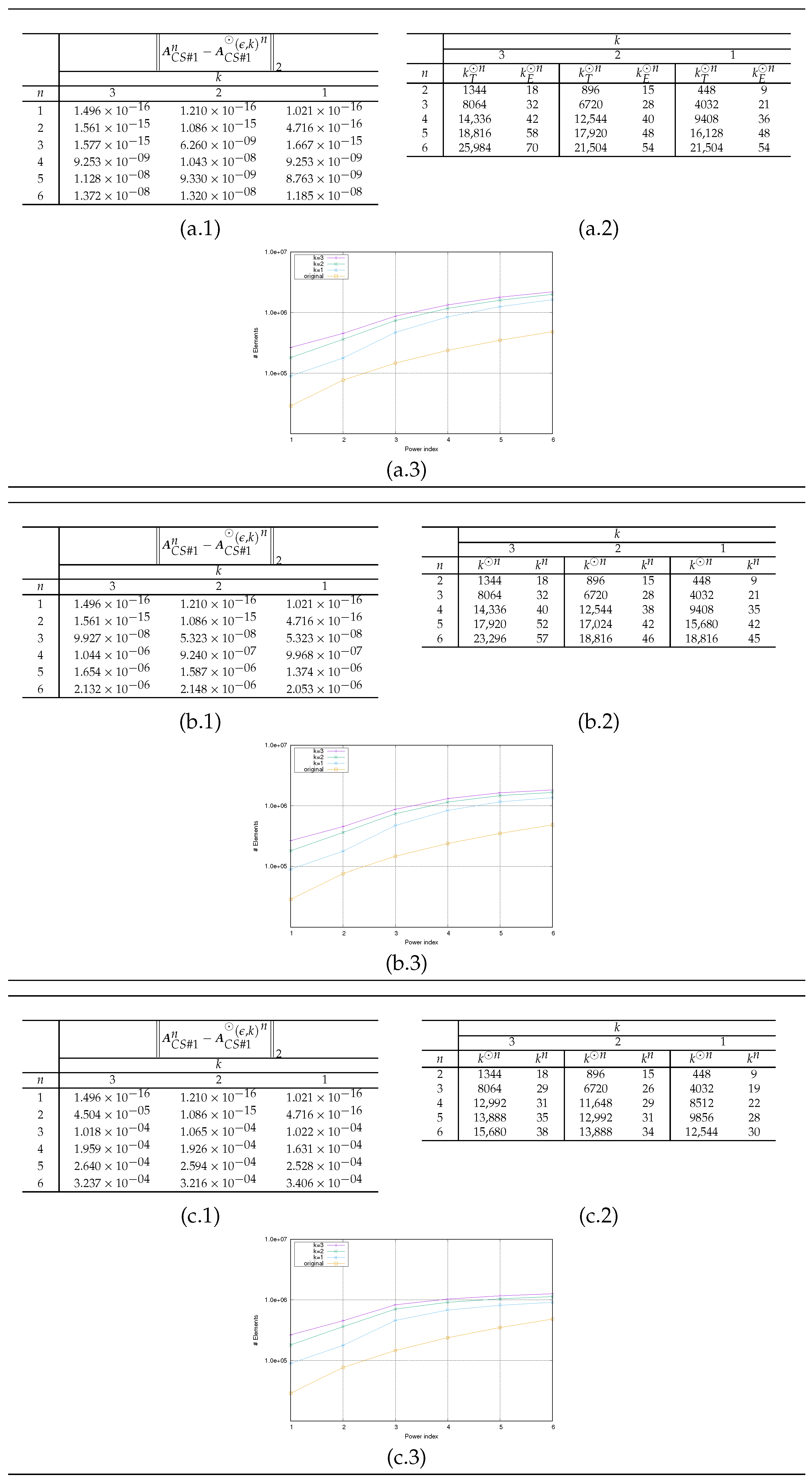
Matrices from three case studies are considered, and case studies are described in the following.
Case Study #1 The matrix is obtained by using the Matlab Airfoil Example (see [
41] for details). The matrix
is structured and sparse and its condition number in L2 norm is
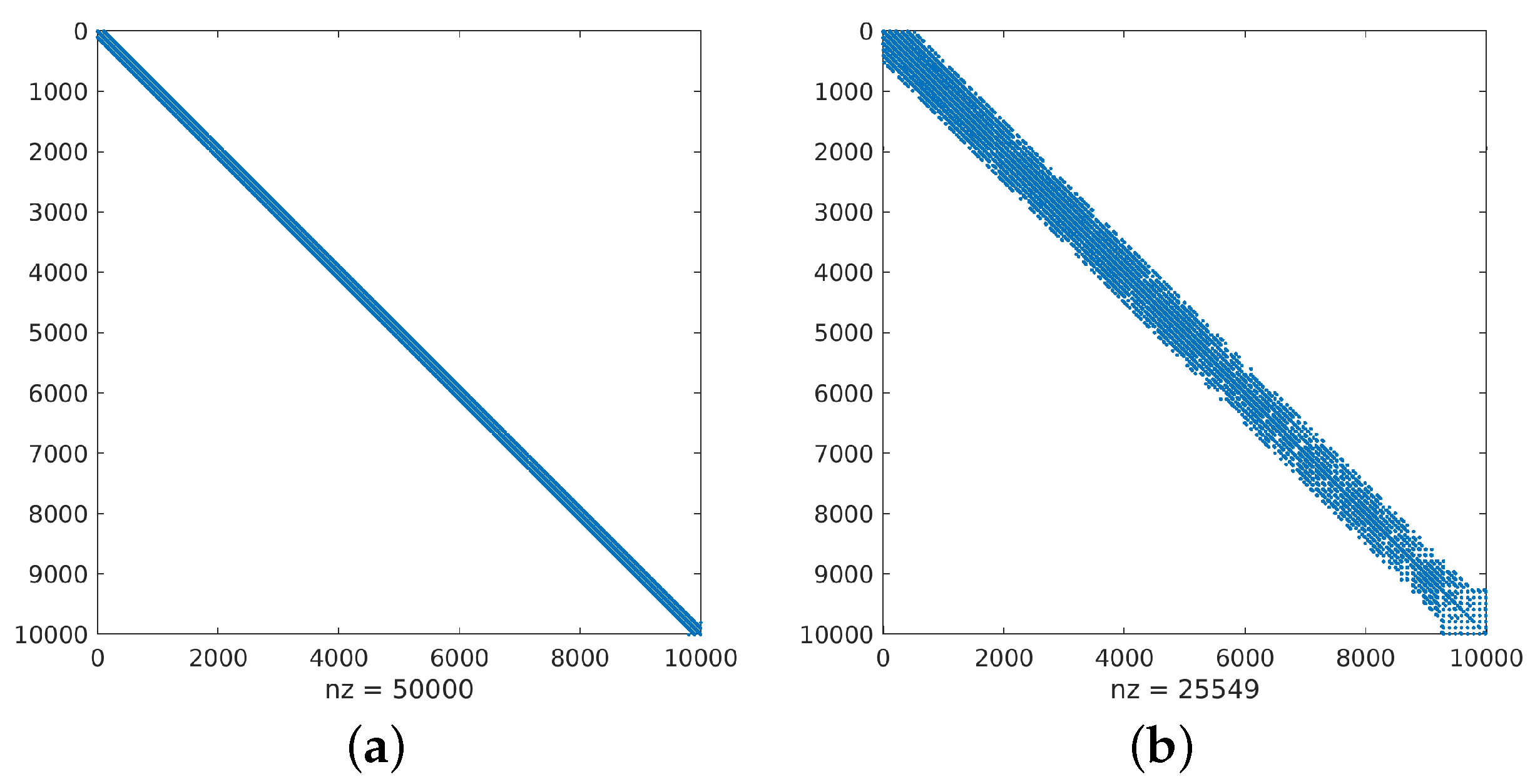
. The sparsity pattern of
, and its first six
n-powers
, are presented in the first row of images in
Figure 2.
Case Study #2 The matrix is obtained from the SPARSKIT E20R5000 driven cavity example (see [
42] for details). The matrix
is structured and sparse and its condition number in L2 norm is
. The sparsity pattern of
, and its first six
n-powers
, are presented in the first row of images in
Figure 3.
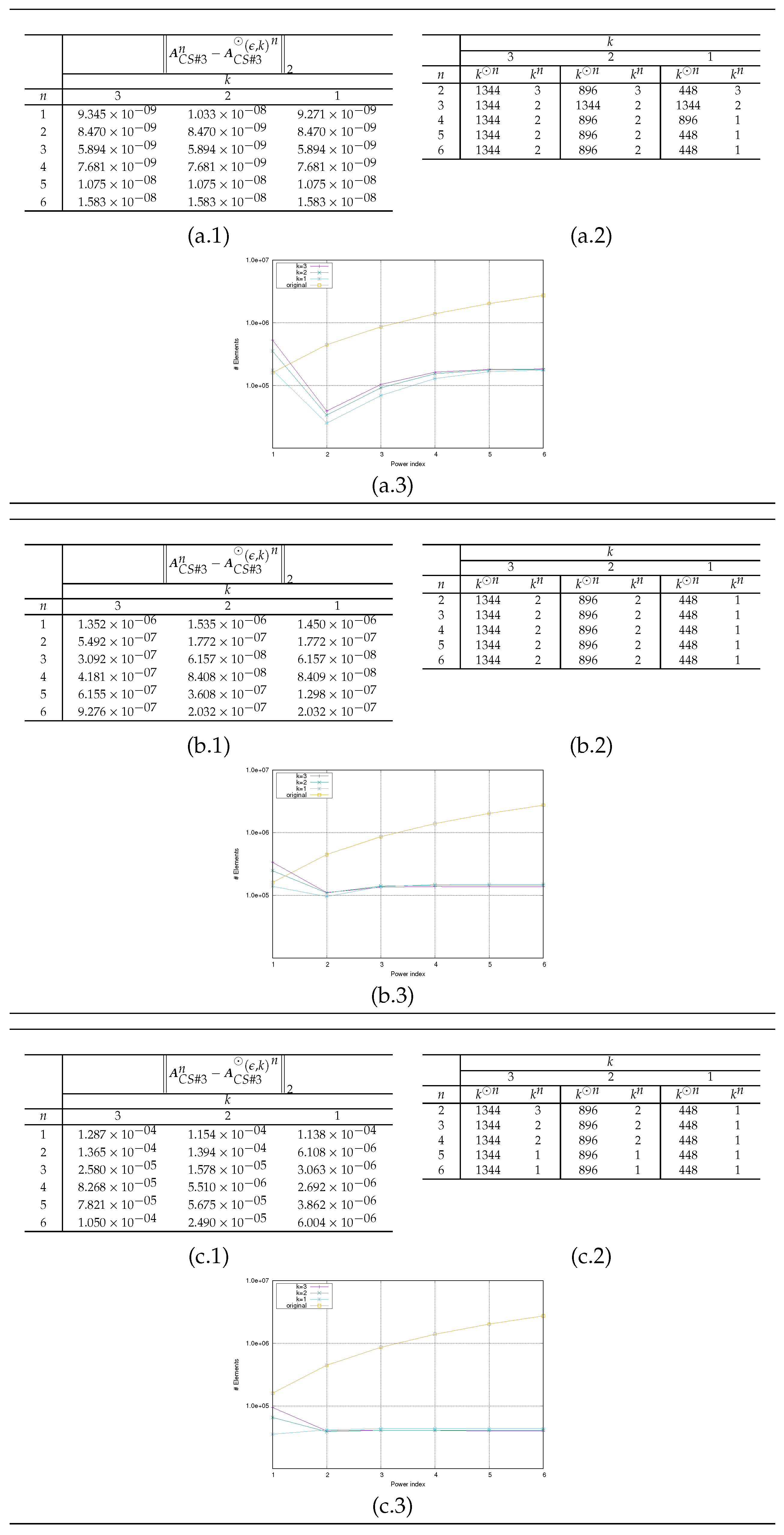
Case Study #3 The matrix is obtained from the Harwell–Boeing Collection BCSSTK24 (BCS Structural Engineering Matrices) example (see [
43] for details). The matrix
is structured and sparse and its condition number in L2 norm is
. The sparsity pattern of
, and its first six
n-powers
, are presented in the first row of images in
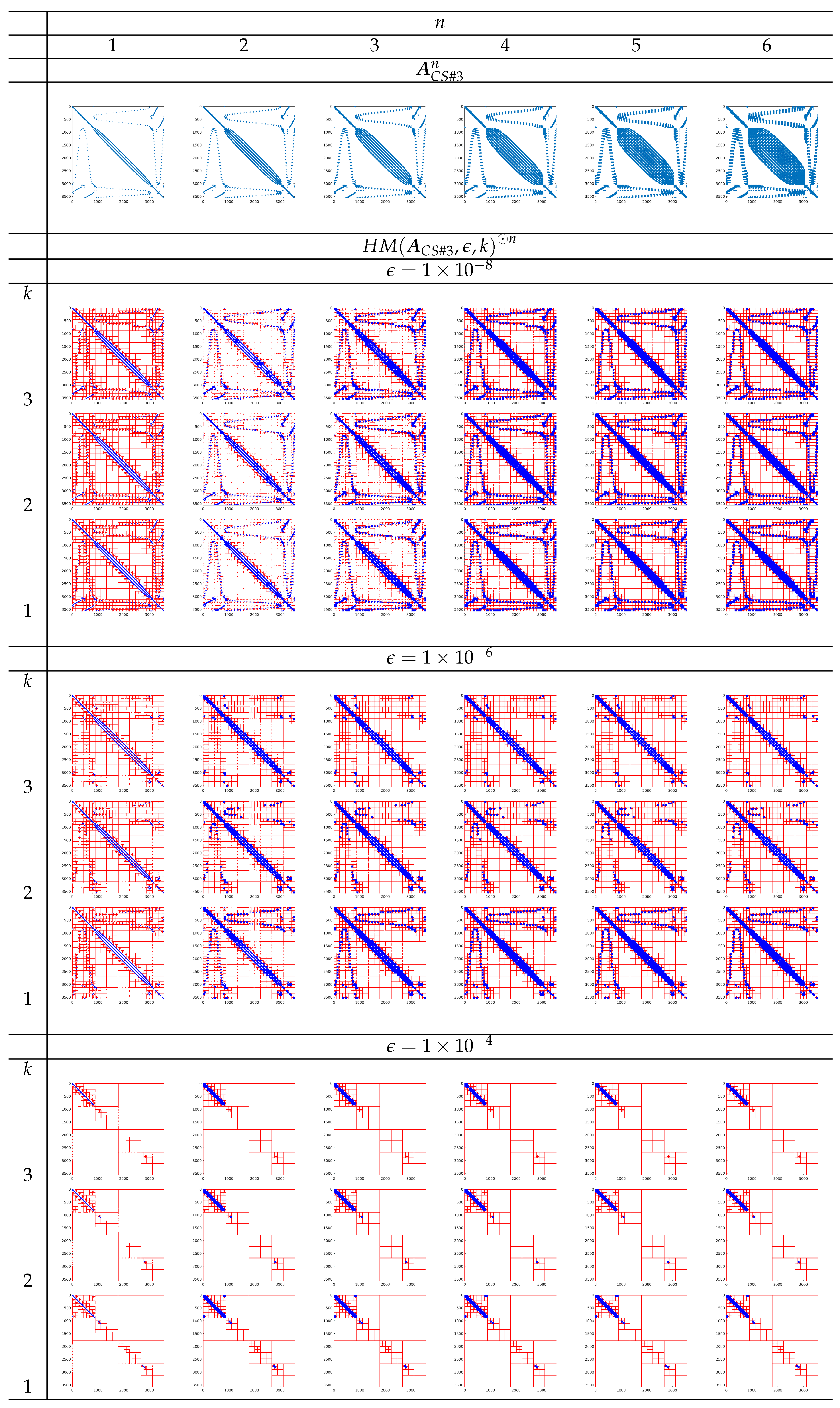
Figure 4.
All the considered matrices
are scaled by the maximum value of the elements. From the first row of the images in
Figure 2,
Figure 3 and
Figure 4, we can observe that the sparsity level of matrices decreases when the value of power degree
n increases.
In
Figure 2,
Figure 3 and
Figure 4, HM representations
for the values of
, and
of matrices
are shown as a sparsity pattern, where red and blue colors, respectively, represent the admissible and inadmissible blocks. The admissible blocks are represented by red marking just the elements of each sub-block occupied by the elements of its rank-
k approximation factors.
The presented results have the aim to
evaluate the propagation of the error
as a function of
n, where
denotes the natural representation of the HMs
(see (a–c).1 in
Figure 5,
Figure 6 and
Figure 7);
compare the number
of the nonzero elements needed to represent
and the number
of the total nonzero elements in both admissible and inadmissible blocks of
(see (a–c).3 in
Figure 5,
Figure 6 and
Figure 7);
compare theoretical value
(obtained by repetitively applying the estimation (
30)) with the effective value
(see (a–c).2 in
Figure 5,
Figure 6 and
Figure 7). The value of
is determined at each step
n as
based on the following actions
- –
after the computation of the product (
32) by Algorithm 5, for each admissible block of
(identified by couple
of indices sets), we compute the value
for which the corresponding block of
can be considered admissible (with respect to
and
);
- –
we compute
as
where
is the set of the admissible blocks of
.
The sparsity pattern representation in
Figure 2,
Figure 3 and
Figure 4 shows how admissible and inadmissible blocks are distributed. Such information should help to analyze which matrix structure is best suited, in terms of memory occupancy, for an HM representation.
the theoretical estimate
is a large overestimation of the actual value
computed in the operations (see plots (a–c).2 in
Figure 5,
Figure 6 and
Figure 7);
for all the
considered, the choice in
k does not substantially modify the evolution of the error
as
n varies (see plots (a–c).1 in
Figure 5,
Figure 6 and
Figure 7);
since higher values of
k imply a higher number of elements in the HM representation, it is convenient to choose the value of
(see plots (a–c).3 in
Figure 5,
Figure 6 and
Figure 7);
some matrices seem to be more suitable than others for HM representation. In particular, it seems that matrices with a sparsity pattern that is not comparable to the one of a band matrix can be more effectively represented both in terms of the number of elements (for example, see the sparsity pattern for the matrices obtained from the Example Test #3 in
Figure 4) and in terms of error evolution
.
From
Figure 5,
Figure 6 and
Figure 7 and
Figure 2,
Figure 3 and
Figure 4, we can deduce that, among the example matrices proposed, the one that guarantees the best performance in terms of memory occupancy is the matrix
. Indeed, the yellow line in plot (a–c).3 in
Figure 7 almost always, depending on the value of
, remains
above the other lines in the same plot. We recall that the yellow line represents the trend, as a function of power degree
n, of number
of the nonzero elements needed to represent
; the other lines, each for different values of
k, represent the number
of the total nonzero elements in both admissible and inadmissible blocks of
. The same behavior is not observable for the other example matrices; indeed, for matrix
, the yellow line always remains
below the other lines (see plot (a–c).3 in
Figure 5); for matrix
, the yellow line sometimes remains
above the other lines; generally, all lines are overlapping (see plot (a–c).3 in
Figure 6). From images in
Figure 4, we can observe that the admissible blocks concentrate near the diagonal, while the inadmissible blocks approximate the off-diagonal blocks with few elements the lower the required approximation precision
is (see images related to
). The matrix
has the best performance also in terms of preservation of the accuracy in HM representation of matrices. Such declaration is supported by error values reported in plots (a–c).1 in
Figure 7 compared with the homologous tables in
Figure 5 and
Figure 6.
Figure 2.
Sparsity representation for Example Test #1.
Figure 2.
Sparsity representation for Example Test #1.
Figure 3.
Sparsity representation for Example Test #2.
Figure 3.
Sparsity representation for Example Test #2.
Figure 4.
Sparsity representation for Example Test #3.
Figure 4.
Sparsity representation for Example Test #3.
Figure 5.
Results for Example Test #1: (a), (b), (c). (a–c).1 Trend of the error . (a–c).2 Trends of the numbers and . (a–c).3 Trends of the numbers and .
Figure 5.
Results for Example Test #1: (a), (b), (c). (a–c).1 Trend of the error . (a–c).2 Trends of the numbers and . (a–c).3 Trends of the numbers and .
Figure 6.
Results for Example Test #2: (a), (b), (c). (a–c).1 Trend of the error . (a–c).2 Trends of the numbers and . (a–c).3 Trends of the numbers and .
Figure 6.
Results for Example Test #2: (a), (b), (c). (a–c).1 Trend of the error . (a–c).2 Trends of the numbers and . (a–c).3 Trends of the numbers and .
Figure 7.
Results for Example Test #3: (a), (b), (c). (a–c).1 Trend of the error . (a–c).2 Trends of the numbers and . (a–c).3 Trends of the numbers and .
Figure 7.
Results for Example Test #3: (a), (b), (c). (a–c).1 Trend of the error . (a–c).2 Trends of the numbers and . (a–c).3 Trends of the numbers and .
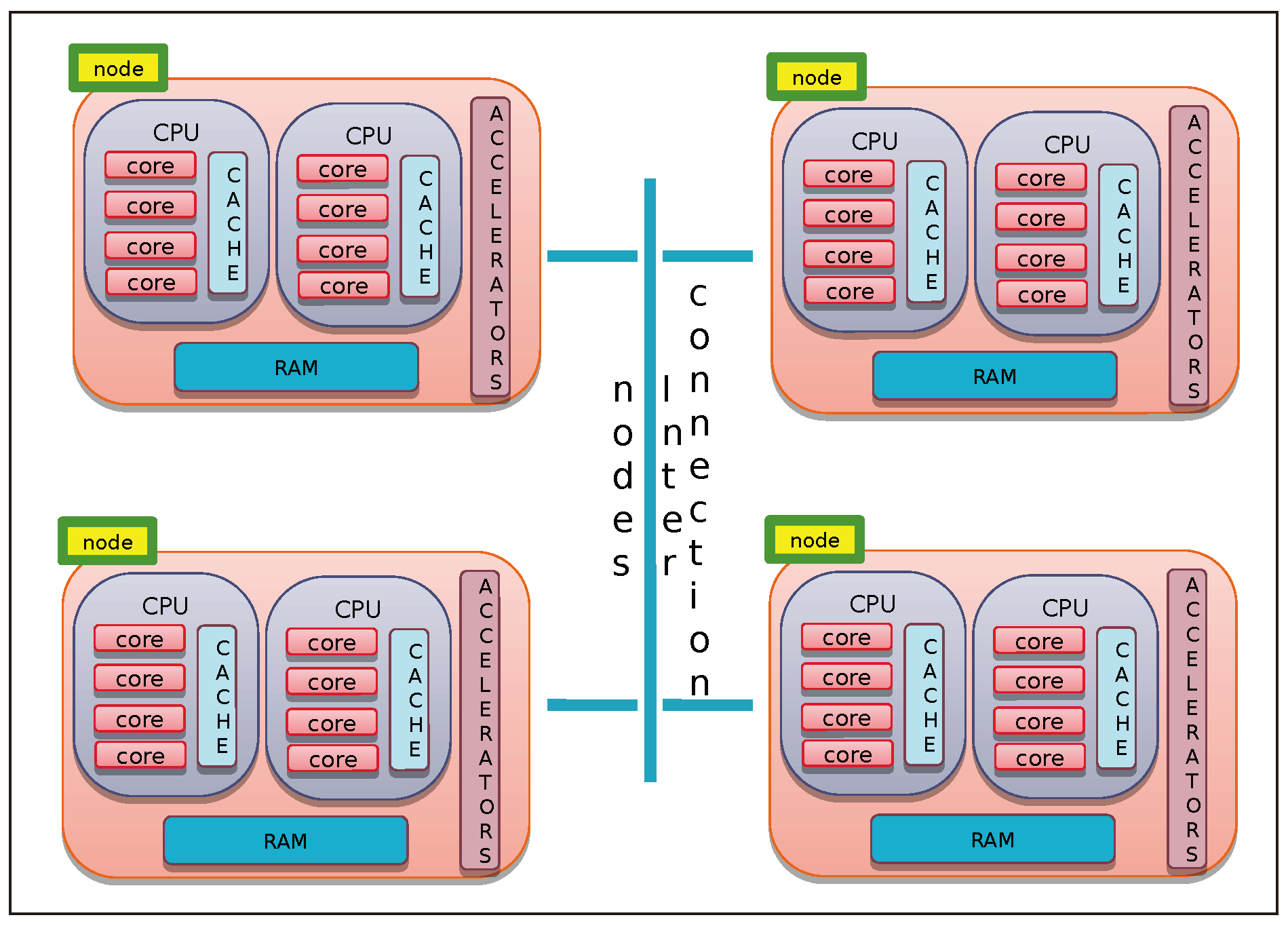
All the proposed algorithms related to basic linear algebra operations based on the HM representation can be easily parallelized, due to their recursive formulation, by distributing computations across the different components of the computing resource hierarchy. As an example, we report in Algorithm 6 a possible parallel implementation of Algorithm 3.
| Algorithm 6 Parallel matrix–vector multiplication of the -matrix of blockwise rank k (defined on block cluster quad-tree ) with vector . The index sets to be used in the first call to the recursive ParHMatrix-MVM procedure are such that . |
- 1:
procedure ParHMatrix-MVM(, , , , ) - 2:
Input: , , , , - 3:
Output:
- 4:
if then ▹ is not a leaf of - 5:
parallel for each do num_tasks () reduction(+:) - 6:
ParHMatrix-MVM(, , , , ) - 7:
end parallel for - 8:
else ▹ is a leaf of , then execute the GEMV BLAS2 operation - 9:
if ( is admissible) then - 10:
- 11:
- 12:
GEMV(, , , , , ) - 13:
- 14:
GEMV(, , , , , ) - 15:
else - 16:
- 17:
- 18:
GEMV(,,,,,) - 19:
end if - 20:
end if - 21:
end procedure
|
The pseudocode listed borrows the constructs used by tools such as
OpenMP [
44]: in particular, it uses the
parallel for construct to indicate the distribution of the instructions included in its body among
concurrent tasks, while the
reduction instruction indicates that the different outputs of the vector
must be added together at the end of the cycle.
The value of variable , at each level l of the block cluster quad-tree , is assumed to be such that , where is the cardinality of the set of sons of the index subset . If the value of divides such cardinality, at most, tasks are spawned, and each task executes new call to ParHMatrix-MVM procedure. If , the execution of the l-th level of Algorithm 6 coincides with that of Algorithm 3.
We recall that BLAS (Basic Linear Algebra Subprograms) are a set of routines [
45] that provide optimized standard building blocks for performing primary vector and matrix operations. BLAS routines can be classified depending on the types of operands: Level 1: operations involving just vector operands; Level 2: operations between vectors and matrices; and Level 3: operations involving just matrix operands. The operation
is called a
GEMV operation when
,
,
,
and
are, respectively, a matrix, two vectors, and two scalars.
The
GEMV BLAS2 operation needed at lines 12 and 14 and 18 in Algorithm 6 is implemented by using the most effective component (identified by the macro
) of the computing architecture by a call to optimized mathematical software libraries available for that component (for example, the multithread version of the
Intel MKL [
46] library or the
cuBLAS [
47] library when using, as
, respectively, the Intel CPUs or the NVIDIA GP-GPU accelerators. All the issues related to the most efficient memory hierarchy accesses are delegated to such optimized versions of the BLAS procedures.
In
Figure 8, an example of the execution tree of Algorithm 6 is shown. In the left part of
Figure 8, the block structure of the
-matrix
is defined on block cluster quad-tree
, where
is represented. The
admissible and
inadmissible blocks are represented, respectively, by yellow and red boxes. In the execution tree of Algorithm 6 (see the right part of
Figure 8) the
leaves are represented by a green box. At each of the two levels of the tree, the considered value for
is
. The following steps are executed:
Starting from level , concurrent tasks are spawned, the task with identification number is related to a leaf, and then, the block being an admissible one, there is the procedure compute contribution to the sub-block of vector related to the index subset by code at lines 12 and 14 of Algorithm 6. Each of the remaining tasks execute a parallel for each spawning other concurrent tasks executing at the following level , with a total of concurrent tasks.
At the level , all the block are leaves. If the blocks are admissible, they are used to compute contributions to the sub-blocks of vector by code at the lines 12 and 14 of Algorithm 6; otherwise, the same sub-blocks are updated by code at the line 18. In particular, assuming that the variable is used to represent the task identification number of a task spawned at the level l by a task with identifier, at the -th level, ,
- –
tasks with identification numbers
compute contributions to sub-blocks of
related to the index subset
and tasks with identification numbers
update sub-blocks of
related to the index subset
. Then, all the tasks spawned from task
(see
Figure 8(b.1)) compute contributions to sub-blocks of
related to the index subset
.
- –
In the same way, tasks with identification numbers
compute contributions to sub-blocks of
related to the index subset
, and tasks with identification numbers
compute contributions to sub-blocks of
related to the index subset
. Then, all the tasks spawned from task
(see
Figure 8(b.2)) compute contributions to sub-blocks of
related to the index subset
.
- –
In the same way, the tasks with identification numbers
(see
Figure 8(b.3)) also compute contributions to sub-blocks of
related to the index subset
.
At the termination of parallel for at level , the contributions to sub-blocks of related to the index subset and are summed together (by means of the reduce operation) to obtain the final status for vector .


