3.1. Overview of Framework
Existing methods for extracting feature points under large viewpoint changes share a common characteristic: they require exhaustive extraction of feature points from a large number of images taken from different viewpoints. Then, they search for similar images to perform feature point matching. This leads to extremely high time complexity, and even more inaccuracy because of the error propagation. The core motivation of our framework lies in addressing the trade-off between computational efficiency and robustness in large viewpoint changes by integrating sparse affine simulation with adaptive thresholding, which distinguishes our method from existing brute-force matching approaches.
If the transformation matrix between the two images was known in advance, it could directly replace the exhaustive matching process. This would improve both the speed and accuracy of the method. To this end, we draw on the idea of affine simulation from ASIFT. While ASIFT achieves affine invariance through dense sampling, its computational redundancy limits practical applicability. Our key innovation lies in redesigning the sampling strategy to balance coverage and efficiency, which is critical for real-time scenarios. By sparsely optimizing the longitude sampling points in the affine simulation, we estimate the transformation matrix between images. Using this matrix, we align the perspective distortions between the two images with viewpoint changes. This effectively eliminates the viewpoint transformation between images, enhancing the stability of feature point extraction under large viewpoint changes.
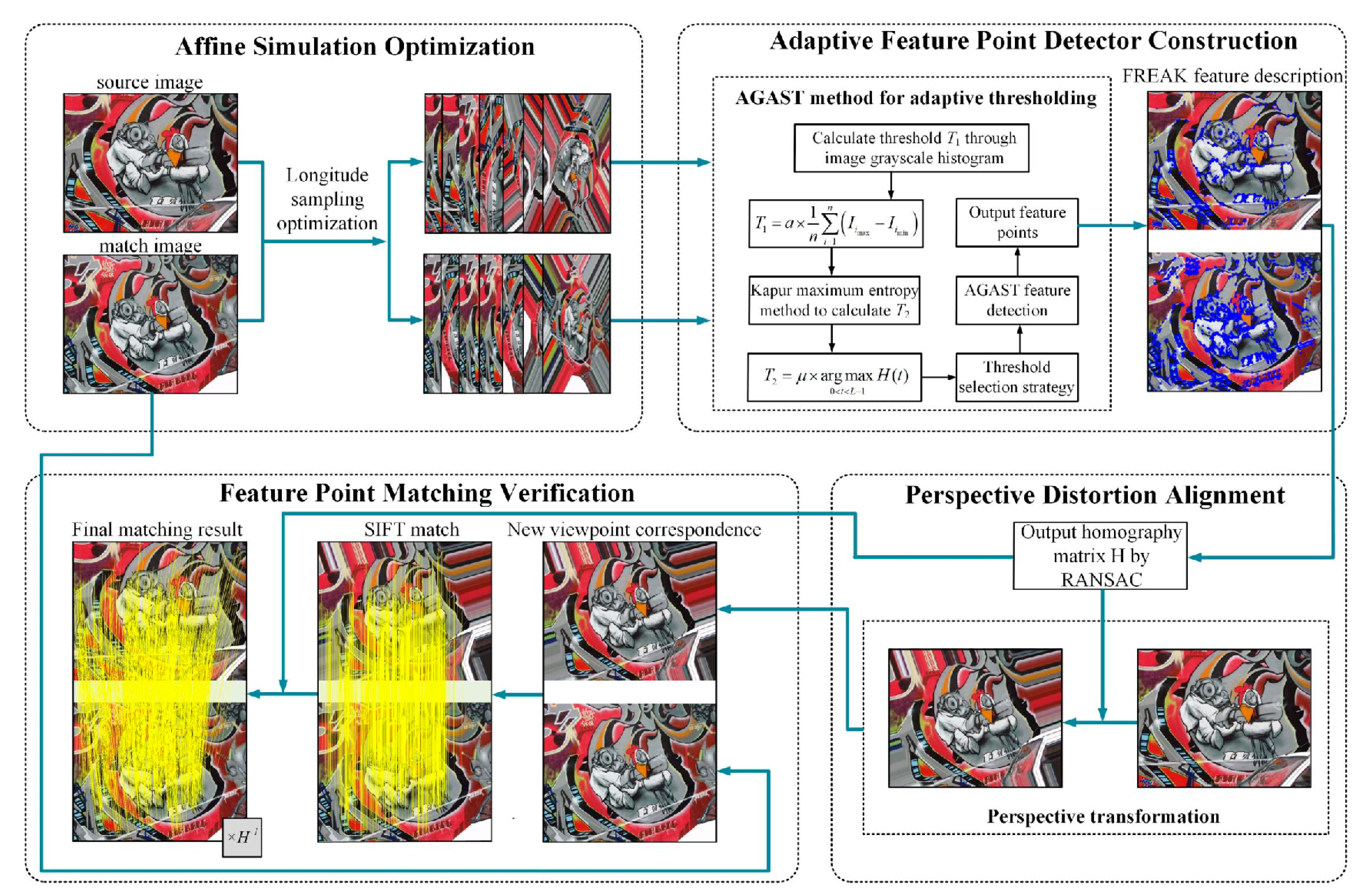
The overall framework of our method is shown in
Figure 1. It includes four components: affine simulation optimization, adaptive feature point detector construction, perspective distortion alignment, and feature point matching verification. The uniqueness of our framework stems from the synergistic design of these components: (1) affine simulation optimization reduces redundancy while preserving critical viewpoints, (2) adaptive thresholding dynamically balances feature quantity and quality, (3) perspective distortion alignment leverages homography estimation for distortion correction, and (4) SIFT-based verification ensures robustness. This integration addresses limitations of isolated module improvements in prior works.
First, based on the affine simulation strategy, we designed a sparser affine simulation model by adjusting the step size of longitude sampling. Then, utilizing the grayscale information of the images and incorporating Kapur’s maximum entropy method, we designed an adaptive AGAST [
29] feature point detector that supports dual thresholds.
Next, based on the FREAK [
27] descriptor, we used the homography matrix
. This matrix, generated by the Random Sample Consensus (RANSAC) algorithm [
42], was used to perform an inverse perspective transformation on the source image. Finally, by applying the inverse of the homography matrix, we transformed the SIFT matching points from the transformed image back to the original image, thereby verifying the stability of feature point extraction.
Below are descriptions of the details of each part, including affine simulation optimization, adaptive feature point extraction, perspective distortion elimination, and feature point matching verification.
3.2. Affine Simulation Optimization
Affine-invariant feature point extraction can be considered an extension of scale-invariant feature point extraction to handle non-uniform scaling and tilting. This means that there are different scaling factors in two orthogonal directions, and angles are not preserved.
Non-uniform scaling not only affects position and scale but also the local feature structures of the image. Therefore, scale-invariant feature point extraction methods fail under significant affine transformations.
The affine camera model is represented by the matrix shown in Equations (1)–(6).
and are the translation variables in the and directions, is the camera’s rotation variable, is the uniform scaling factor, is the longitude, and is the latitude. These two variables define the direction of the camera’s principal optical axis.
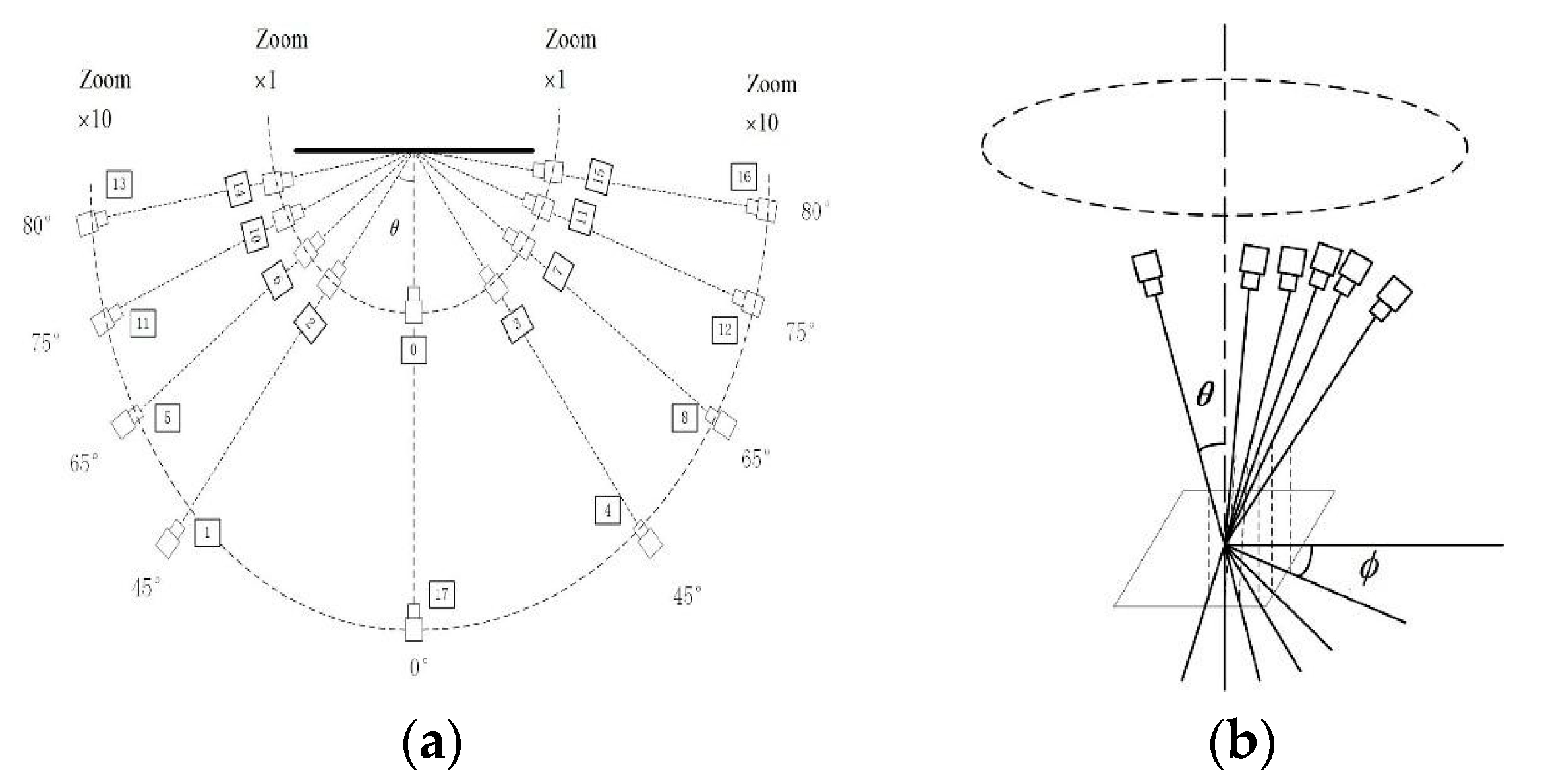
Therefore, the viewpoint changes caused by camera movement when capturing the same object can be approximated with an affine transformation model. This model helps simulate the effects of different viewpoints. By adjusting the latitude and longitude angles, the affine transformation simulates images from different viewpoints. The observation hemisphere of these angles is shown in
Figure 2. The black dots in the figure represent sampling points at various latitudes and longitudes. Corresponding simulated images with affine deformation can be generated based on the affine matrix. Refer to the following description for the sampling rules of the latitude angle
and longitude angle
.
- 1.
The latitude angle , where and have a one-to-one correspondence. The tilt corresponding to can be with ;
- 2.
The longitude angle and have a one-to-many relationship, with . is a positive integer that satisfies and .
Based on the one-to-many relationship between the parameter
and the longitude angle
, it can be seen that the value of
significantly affects the time complexity of affine transformations. When
, the sampling points before optimization are shown in
Figure 3a, where the values of
at different latitudes are
, with a total of 42 sampling points. For affine simulation, the smaller the value of
, the more identical information is contained in the simulated images, and the more feature points can be extracted from the simulated images, resulting in more matched feature points.
However, since this paper applies affine simulation to estimate camera motion parameters under large viewpoint changes, it is not necessary to have a large number of matching points during this process. Having too many feature points would create redundancy in the feature information and increase computational cost. This would not significantly improve the estimation of camera motion parameters. The goal of the affine simulation optimization strategy in this section is to enhance the efficiency of feature point extraction during affine simulation. It also aims to cover as many different viewpoints as possible, supporting efficient camera motion parameter estimation under large viewpoint changes.
Therefore, to balance the accuracy and time complexity of the feature point extraction method in this paper, the step size for longitude sampling is increased to reduce redundant sampling points and achieve optimization. The optimized 12 sampling points are shown in
Figure 3b, where the values of
at different latitudes are
The one-to-many relationship between the optimized
and
can be expressed as:
.
As shown in
Figure 3b, optimizing the longitude sampling significantly reduces the number of simulated viewpoint samples. Despite this reduction, the optimized sampling still effectively covers the affine simulations of different viewpoints. It meets the requirements for camera motion parameter estimation and reduces the computational time overhead of affine simulation.
3.3. Adaptive Feature Point Detector Construction
In this section, we utilize AGAST [
29] for feature point detection. In AGAST, the threshold represents the minimum contrast between potential feature point locations and their surrounding pixels. A higher threshold leads to fewer detected feature points; conversely, a lower threshold results in more feature points. Because the AGAST algorithm requires manual threshold setting, these fixed thresholds cannot meet the demands of different scenarios. To address this issue, we introduce a dual-threshold constraint during feature point extraction. This approach enables adaptive threshold setting for the AGAST algorithm and simultaneously extracts initial feature points to support subsequent homography matrix estimation.
- 3.
Setting of Threshold T1
We determine the dynamic threshold
of the AGAST algorithm based on the degree of variation in image grayscale contrast. Specifically, we first set the vertical axis range of the histogram. This range represents the frequencies of different grayscale values. It was set to [0, 255] as the basis for calculating the threshold in the next step. This serves as the basis for calculating the threshold in the next step. Then, we sample the
grayscale values that appear most frequently and least frequently. The dynamic threshold
is defined as shown in Equation (7).
where
and
represent the
grayscale values that appear the least and the most in the image, respectively, and
is the proportional coefficient. In the experiments of this paper,
is set to 10, and
is set to 0.3.
- 4.
Setting of Threshold T2
It is insufficient to merely use the variation in image grayscale values as a threshold constraint for the AGAST algorithm. When an image has weak texture features but strong brightness variations, relying solely on the grayscale histogram to set the AGAST threshold can result in unreasonable threshold settings. This may lead to an insufficient number of feature points being detected. Therefore, we introduce a dynamic threshold
T2 to further constrain the AGAST algorithm’s threshold. We adopt Kapur’s maximum entropy method [
43,
44] to determine
T2. This method uses conditional probabilities to describe the grayscale distributions of the image’s foreground and background, thereby defining their respective entropies.
In the following, we use an 8-bit grayscale image as an example for illustration. Accordingly, the grayscale range in this algorithm is represented as
, where
. The image is divided into foreground and background based on a threshold. The foreground consists of pixels with grayscale values greater than or equal to the threshold, while the background comprises pixels with grayscale values less than the threshold. Therefore, each pixel in the image belongs either to the foreground or to the background. Therefore, under the threshold
, the image is divided into two subclasses
and
. At this point, the entropy of the image includes the background entropy component
and the foreground entropy component
, as shown in Equations (8) and (9)
where
is the entropy of the image, defined as
,
and
.
represents the probability density
.
represents the total number of pixels,
.
represents the number of pixels with a grayscale value of
.
Equation (10) represents the entropy of the entire image under a certain threshold segmentation. Using the image histogram, the maximum entropy for image threshold segmentation is calculated. The algorithm traverses the grayscale range of the image (0 to 255), computing the entropy value at each grayscale level. The threshold value
is the one that maximizes the entropy
of the image. This threshold
is then selected for segmentation. That is
, where the optimal threshold
is given by Equation (11).
where
is the proportional coefficient. Since the threshold of the feature points is related to the image contrast, Kapur’s maximum entropy method is used to identify the points where the grayscale variation in the image is most significant.
Suppose the coordinates of a pixel on the image are , and the grayscale value at that point is . In the AGAST algorithm, the pixel will only be selected as a feature point if the grayscale values of the pixels on the Bresenham circle around it are all greater than or all less than (where is the threshold, set as or in practical applications).
It is worth noting that the affine simulation strategy proposed by Morel et al. [
7] only varies two variables in the affine transformation matrix. This requires that the feature point extraction algorithm used in affine simulation must satisfy the remaining four degrees of freedom in the model. Since the SIFT algorithm possesses translation, rotation, and scale invariance, ASIFT achieves full affine invariance. Similarly, the binary descriptor FREAK also has strong translation, rotation, and scale invariance. Therefore, in this paper, we use the adaptive AGAST feature detection method combined with the FREAK feature descriptor. This combination highlights the adaptive nature of the initial feature point extraction. Moreover, our algorithm significantly outperforms the ASIFT algorithm in terms of execution efficiency.
3.4. Perspective Distortion Alignment
Unlike existing methods based on affine simulation strategies, in this subsection we first estimate the camera motion parameters between two image frames. Then, we eliminate the perspective distortion between the images to reduce the impact of viewpoint changes. Finally, we perform extraction and matching of the final feature points on images adjusted for the new viewpoint relationship.
To estimate the camera motion parameters between two images, it is necessary to detect at least four pairs of matching feature points sufficient to solve the homography matrix. Therefore, in the camera motion estimation stage, the extracted feature points (initial feature points) are required to be successfully matched, and the matching points should be few but precise. This goal is achieved by combining the previously optimized longitude simulation sampling model and an adaptive-threshold AGAST detector. Specifically, we use the adaptive AGAST feature detector for initial feature point detection. These points are then described and matched using the FREAK descriptor, enabling rapid estimation of camera motion parameters.
Perspective transformation is based on the pinhole imaging principle used in conventional cameras. It maps objects from the world coordinate space to the image coordinate space. The inverse perspective transformation is its reverse operation. Perspective transformation can more accurately reflect the viewpoint changes between two images captured during camera motion. Assuming the camera moves from the viewpoint position of the matched image to that of the source image, the perspective transformation between the two images can be performed based on the homography transformation matrix between them. This provides a reliable opportunity for distortion correction.
Therefore, we estimate the camera’s perspective transformation parameters based on affine simulated sampling. This approach is equivalent to obtaining a more precise perspective transformation matrix from matched point pairs derived from 13 pairs of simulated views, each using affine transformation matrices. Therefore, we can utilize the initial feature point correspondences obtained through the affine simulation strategy. Using the homography matrix generated by the RANSAC algorithm with findHomography() in OpenCV, we perform an inverse perspective transformation on the target image. This allows us to achieve perspective alignment between the two images.
3.5. Feature Point Extraction and Matching Verification
By aligning the perspective-distorted images in
Section 3-D, we obtained a new viewpoint relationship. This alignment reduces or effectively eliminates the inconsistencies between the two images caused by viewpoint transformations. Consequently, the stability of matching based on feature point descriptors is enhanced. Furthermore, we selected SIFT, considered the “gold standard” [
45], to perform feature point extraction and matching verification on the image pairs with the new viewpoint relationship.
Since one image from the source image underwent an inverse perspective transformation relative to another image (as shown in
Figure 4), the viewpoint relationship between the original image pairs has changed. The original viewpoint correspondence and the new viewpoint correspondence are shown in
Figure 4a,b, respectively. As a result, the two images in the new viewpoint pair are effectively aligned under the same perspective transformation standard (by multiplying with the inverse homography matrix
). This alignment enhances the stability of feature extraction and matching.
